Embed Size (px)
Citation preview
8/15/2019 Jes Servo Paper
http://slidepdf.com/reader/full/jes-servo-paper 1/16
1Ahmed M. A. Haidar, University of Wollongong, NSW, Australia, E-mail: [email protected]
2 Chellali Benachaiba, University of Bechar, Algeria3
Mohamad Zahir, University Malaysia Pahang, Malaysia
Copyright © JES 2013 on-line : journal/esrgroups.org/jes
Ahmed M. A.
Haidar1,
Chellali
Benachaiba2,
Mohamad
Zahir
3
J. Electrical Systems 9-1 (2013): 84-99
Regular paper
Software Interfacing of Servo Motor with
Microcontroller
JES
Journal of
lectrical
Systems
Automatic control of DC servo motor in terms of rotation angle has played a vital role in theadvance Electromechanical Engineering. Nowadays, the automatic process of motor controlusing a Personal Computer (PC) is commonly used. The controllers are designed to interface between a Computer and Motor. This paper presents the implementation of PICMicrocontroller with Graphical User Interface (GUI) in Matlab to track the rotational angle ofDC servo motor. The movement of slider on GUI will act as an input signal into theMicrocontroller to change the rotation angle. A simulation on the performance of the system has been carried out using Proteus software interfaced with Matlab and the controller was testedon real-time application. Results show that the use of PIC Microcontroller and GUI in Matlabis an advantage solution to control the rotational angle.
Keywords: Automatic control; Matlab GUI; DC servo motor; PIC Microcontroller; Proteus software
1. Introduction
DC Servo Motors become an important device in a wide range of industrial applications
that require high dynamics on position control such as numerically controlled machinery,
robotics, automation and other mechanism where the starting and stopping functions are
quickly and accurately [1,2]. These applications require a high-speed control accuracy and
good dynamic respond. In robotic applications, servo motors are used to move the robotic
arm to a relevant position by means of controllers in the automated manufacturing lines of
industries [3, 4]. The rotor construction of servo motors made of special material with lessweight to decrease the inertia of armature but capable to produce the necessary magnetic
flux. Low rotor inertia increases the capability of immediately starting and stopping during
the on-off conditions. The high cost of servo motor becomes a major issue. Therefore, the
small-scale manufacturers or users cannot afford to use this type of DC Motor.
DC Servo Motors have a large market share in the Industry Automation & Drive
Technologies. The common problems in controlling the servo motor with specific speed
and position is the tuning of the parameters. Many different techniques have been proposed
in order to cope with the tuning problems. Fuzzy Logic is one of the implemented
techniques that have been used to sort out with these problems [4, 5]. The nonlinearity of
the servo motor is one of the difficulties in controlling the servo motor. Since the load
pressure varies over a wide range under internal parameter variations and external
disturbances (load torque variations), these two factors tend to induce a higher degree of
nonlinearity [6, 7].
Along with the rapid development of digital and computer control technology,
embedded hardware interfacing with the technology of simulink software is undergoing
tremendous change. Currently, there are several commercially available embedded
hardware interfacing, including advanced RISC machine (ARM), digital signal processing

8/15/2019 Jes Servo Paper
http://slidepdf.com/reader/full/jes-servo-paper 2/16
J. Electrical Systems 9-1 (2013): 84-99
85
(DSP), application-specific integrated circuit (ASIC), and field programmable gate array
(FPGA). Among them, FPGA have a number of programmable logic resources that make it
possible to integrate with microprocessors to form a complete embedded system and
perform complex computations in hardware [8]. Many researchers have investigated servo
system simulation focusing on principle teaching and maintain training [5, 9, 10, 11, 12]. In
[10], an integrated Matlab/Simulink with neural network and LabVIEW was designed to
develop a SCADA real-time AC servo motor monitoring control system. Another simulink
testing system is introduced in [5] for intelligent robot control using Matlab environment
and Turbo C software. Both systems are an effective solution to simplify the data
processing with a high performance servo motor tracking scheme.
The traditional test system can no longer meet the rapid development of modern servo
system. Therefore, a new kind of automatic testing systems incorporating monitoring
software are needed. Ref. [13] discusses the development of simulation software models for
two axis servo platform based on the National Instruments LabVIEW. The system is used
to evaluate and test an advanced servo control algorithms before being implemented intothe actual system. An overall network structure of a developed system in layers was
designed in [14]. The system consists of advanced test instruments, user-friendly virtual
interface, database server, LAN clients and web server. The connection between LabVIEW
and database is realized by using the Database Connectivity Toolkit. To simplify the
program, Virtual Instruments Software Architecture was applied with written commands to
the buffer, instead of considering any specific communication protocols.
This paper presents the implementation of computer interfacing control for servo motor
based on Matlab coding imbedded in microcontroller. Proteus software was used to
simulate the hardware and verify the Matlab coding for real time application. In this work,
some of the components can be changed easily to upgrade the performance of the system.The work is organized as such that, section 1 gives a brief introduction of DC servo motor
with the existing software. A literature review on DC motors and control methods are
presented in Section 2. Section 3 presents the principle operation of DC servo motor
control. The methodology, software simulation and hardware implementation are outlined
in Sections 4 and 5 respectively. The results are discussed in Section 6, while Section 7
drafts the conclusion.
2. A review on dc servo motor control
According to the variety of DC motor, different techniques are designed to control theDC motor and overcome the volatility characteristics of the physical DC motor system
itself. The types of DC motor are permanent magnet, winding, stepper and servo, etc.
Permanent magnet DC motor has a small size and compact compare to other types of DC
motor but the magnetic field strength cannot be varied. Winding DC motors which are
shunt-wound, series-wound and compound provide a very high range speed and torque.
However, the stepper motor has a higher precise speed control and large torque at low
speed but in terms of cost, this type is expensive. Alternatively, servo motor is an important
for the application at the industries due to its ability of quick response and precise
positioning but motor is expensive [1].
A servo motor is an electromechanical device in which the electrical input determines
the position of motor armature. It is actually an assembly of four things: a normal DC

8/15/2019 Jes Servo Paper
http://slidepdf.com/reader/full/jes-servo-paper 3/16
Ahmed M, A, Haidar et al: Software Interfacing of Servo Motor with Microcontroller
86
motor, a gear reduction unit, a position-sensing device and a control circuit. Servo motors
are used extensively in robotics industry and radio-controlled cars. The implemented types
in modern servo systems are AC servo motors based on induction motor designs, DC servo
motors based on DC motor designs, DC brushless motors and AC brushless servo motors
based on synchronous motor designs. These motors are working in a closed loop control
systems where the programmed position of motion and velocity feedback controllers are
required [4]. Different studies and researches have been conducted on the servo motor
control. Currently, the conventional method of servo motor control is based on proportional
integral derivative. Other suggested methods such as artificial intelligence and fuzzy logic
were mentioned in Ref [15]. Usually the control method of fuzzy with a fixed set of
quantizing factor and scaling factor is often used in the fuzzy control [16]. However, the
variations of quantizing factor, scaling factor and control rule in the fuzzy look up table
may significantly affect the speed of DC Motor. In addition, with the same set of fuzzy
control rule, quantizing factor and scaling factor, the variation of membership function will
also affect the control performance of fuzzy control [17, 18].So far, several approaches for robust control have been proposed and considerable
progress was made in this area. The popular techniques primarily intended for linear
systems such as linear Quadratic Gaussian control design with loop transfer recovery
(LQG/LTR) technique and adaptive or self-tuning control. Among the techniques used
mainly for nonlinear systems, the sliding-mode control. Recently, Time Delay Control
(TDC) has also attracted attention as an excellent robust nonlinear control algorithm. The
main purpose of using TDC methods is to assure control performances (such as accuracy,
stability, speed, etc) Generally, TDC uses the time-delayed values of control inputs and
derivatives of state variables at the previous time step to cancel the nominal nonlinear
dynamics and the aforementioned uncertainties. Thus, TDC does not require any real-timecomputation of nonlinear dynamics, nor does it use the parameter estimations as in adaptive
control [19].
Proportional integration (PI) controller is unquestionable as the most common controller
in the process control industry. The main reason for using this controller is its relatively
simple structure, which can be easily understood and implemented in practice. It also
implemented in the sophisticated control strategies, such as model predictive control [20].
PI control is math total of integration error and multiplying of error with constant [21]. A
simplest method to control the rotation speed of a DC motor is to control its driving
voltage. The higher the voltage is the higher speed the motor tries to reach. In many
applications, a simple voltage regulation would cause lots of power loss on control circuit,
thus, a pulse width modulation method (PWM) is used in many DC motor controlling
applications [4, 22]. In the basic PWM method, the operating power to the motors is turned
ON and OFF to modulate the current to the motor. The PWM control method uses the
widths of pulses in a pulse train to control the speed of the motor [23]. The pulses are
arranged such that, only one pulse occurs for every period of the system clock. The duty
cycle of the pulses determines the speed of the motor. Therefore, the higher the duty cycles
the higher the speed [4]. This would give the motor the ability to safely vary the speed from
stand still to its maximum speed. For this reason, the PWM method was chosen to be
implemented in the motor control design. Sometimes, the rotation direction needs to bechanged. In the normal permanent magnet motors, this rotation is changed by changing the

8/15/2019 Jes Servo Paper
http://slidepdf.com/reader/full/jes-servo-paper 4/16
J. Electrical Systems 9-1 (2013): 84-99
87
polarity of operating power (for example by switching from negative power supply to
positive or by interchanging the power terminals going to power supply). This direction
changing is typically implemented using relay or a circuit called an H bridge [3].
The main purpose of interfacing motor control is to implement a closed-loop control of
servo motor position utilizing a local interconnect network (LIN) to allow a series of
similar motors connected together and controlled by master controller. Since the motor is
used for steering and driving systems, a single controller can be used for both functions. A
microcontroller is applied to produce the PWM signal. The control programming based on
computer interfacing to produce the PWM output would eliminate the need for additional
hardware, saving on the overall cost of such a motor drive circuit [24, 25]. The Complex
high-performance controllers such as PID have to be programmed and loaded into the
microcontroller by converting it into hex file. Interfacing the motor with computer
programming is achieved by the generated PWM signal from microcontroller. The control
system on the hardware uses all the necessary features to meet the requirements of LIN
applications [26, 27, 28].
3. Principle operation of dc servo motor control
Servos are controlled by a pulse of variable width. The sent signal of this input pulse is
characterized by a minimum pulse, maximum, and a repetition rate as seen in Figure 1.
Given the rotation constraints of the servo, neutral is defined to be the position where the
servo has exactly the same amount of potential rotation in a clockwise direction as it is in a
counter clockwise direction [29]. The angle is determined by the duration of applied pulse
to the signal wire which is called PWM or Pulse Coded Modulation. The servo should
detect a pulse every 20 ms. The length of the pulse will determine how far the motor turns.For example, a 1.5 ms pulse will make the motor turn to a 90 degree position (neutral
position). The position pulse must be repeated to instruct the servo to stay in position [28].
Fig. 1: Input pulse of servo motor
When a pulse is sent to a servo that is less than 1.5 ms, the servo rotates to a position and
holds its output shaft some number of degrees counter-clockwise from the neutral point.
When the pulse is wider than 1.5 ms, the opposite operation is occurred. The minimal width
and the maximum width of pulse that will command the servo to turn to a valid position are
functions of each servo. Generally the minimum pulse will be about 1 ms wide (some servo
is 0.5 ms) and the maximum pulse will be 2 ms wide (some servo is 2.5 ms). The servo
motor operates in the range of 5 % to 10 % of duty cycles. Figure 2 shows relationship
between pulse and direction of servo motor.
20ms
Pulse Width 0.5ms – 2.5ms
8/15/2019 Jes Servo Paper
http://slidepdf.com/reader/full/jes-servo-paper 5/16
Ahmed M, A, Haidar et al: Software Interfacing of Servo Motor with Microcontroller
88
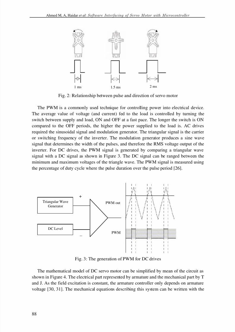
Fig. 2: Relationship between pulse and direction of servo motor
The PWM is a commonly used technique for controlling power into electrical device.
The average value of voltage (and current) fed to the load is controlled by turning the
switch between supply and load, ON and OFF at a fast pace. The longer the switch is ON
compared to the OFF periods, the higher the power supplied to the load is. AC drives
required the sinusoidal signal and modulation generator. The triangular signal is the carrier
or switching frequency of the inverter. The modulation generator produces a sine wave
signal that determines the width of the pulses, and therefore the RMS voltage output of the
inverter. For DC drives, the PWM signal is generated by comparing a triangular wave
signal with a DC signal as shown in Figure 3. The DC signal can be ranged between the
minimum and maximum voltages of the triangle wave. The PWM signal is measured using
the percentage of duty cycle where the pulse duration over the pulse period [26].
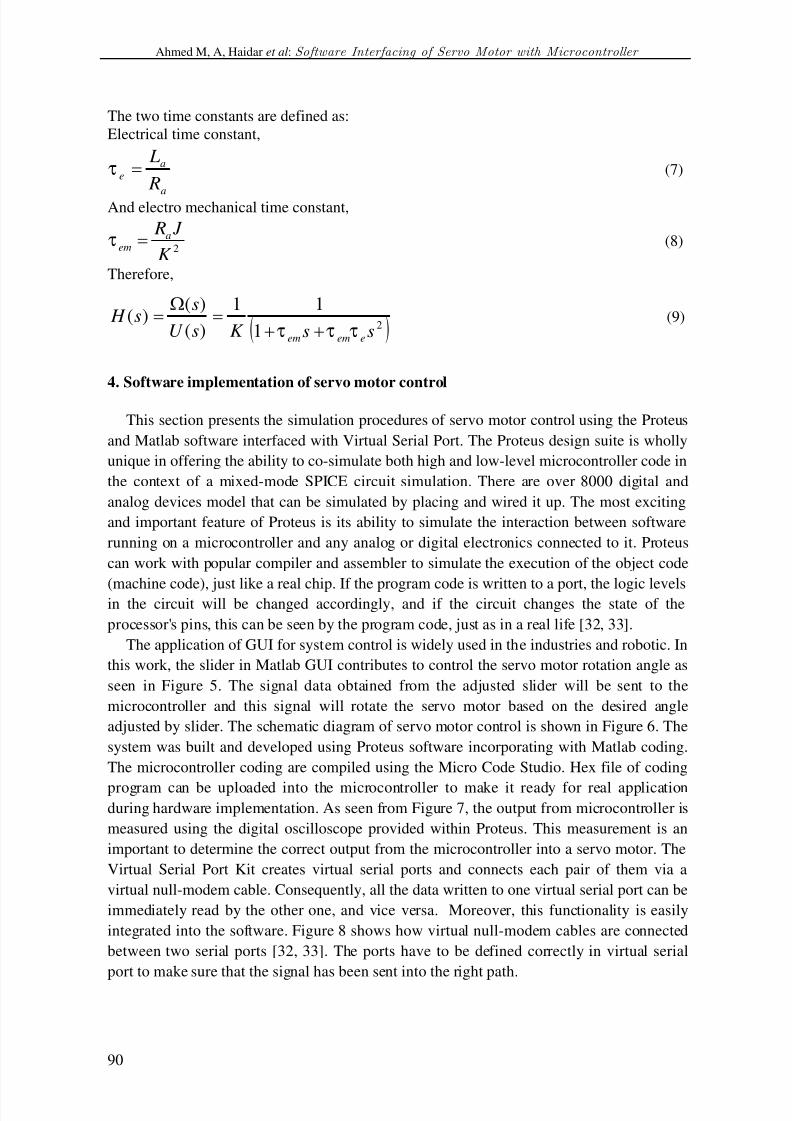
Fig. 3: The generation of PWM for DC drives
The mathematical model of DC servo motor can be simplified by mean of the circuit as
shown in Figure 4. The electrical part represented by armature and the mechanical part by T
and J. As the field excitation is constant, the armature controller only depends on armature
voltage [30, 31]. The mechanical equations describing this system can be written with the
PWM
Triangular Wave
Generator
DC Level
–
+
PWM out
1.5 ms 2 ms1 ms

8/15/2019 Jes Servo Paper
http://slidepdf.com/reader/full/jes-servo-paper 6/16
J. Electrical Systems 9-1 (2013): 84-99
89
assumptions that the loss is included in load torque and neglecting viscous friction constant
[30] as given below,
Fig. 4: DC servo motor equivalent circuit
baaa Edt
diLiRV (1)
TTdt
dJ e
(2)
With,
ωK E b (3)
iK T e (4)
where, i : armature current; aV : armature voltage; a R :armature resistance; a L : armature
inductance; K : torque and back electromagnetic constant ( Nm.A-1
); ω ; rotor angular
speed; eT : electromagnetic torque; T : total load torque; J : rotor inertia.
The control input is the armature voltage aV and the total load torque T is the disturbing
input. The two state variables are armature current i and angular speedω . Then the
previous equations lead to the state space model of DC motor:
T V
J
Li
J
K L
K
L
R
dt
d dt
di
aaaa
a
10
01
0 ωω
(5)
The two state variables excited the angular speed in order to perform a speed regulator
related with the angular speed. Therefore, ω is considered as the output of the system and
aV is the input. Taking into account only these two system variables, the transfer function
of the DC motor is:
2
221
11
)(
)()(
sK
J LsK
J RK sV
ss H
aaa
ω(6)
T
J
ω
La Te
+
–
Eb
Ra
Va
–
+
i
8/15/2019 Jes Servo Paper
http://slidepdf.com/reader/full/jes-servo-paper 7/16
Ahmed M, A, Haidar et al: Software Interfacing of Servo Motor with Microcontroller
90
The two time constants are defined as:
Electrical time constant,
a
ae
R
Lτ (7)
And electro mechanical time constant,
2K
J Raem τ (8)
Therefore,
21
11
)(
)()(
ssK sU
ss H
eemem τττ
(9)
4. Software implementation of servo motor control
This section presents the simulation procedures of servo motor control using the Proteus
and Matlab software interfaced with Virtual Serial Port. The Proteus design suite is wholly
unique in offering the ability to co-simulate both high and low-level microcontroller code in
the context of a mixed-mode SPICE circuit simulation. There are over 8000 digital and
analog devices model that can be simulated by placing and wired it up. The most exciting
and important feature of Proteus is its ability to simulate the interaction between software
running on a microcontroller and any analog or digital electronics connected to it. Proteus
can work with popular compiler and assembler to simulate the execution of the object code
(machine code), just like a real chip. If the program code is written to a port, the logic levelsin the circuit will be changed accordingly, and if the circuit changes the state of the
processor's pins, this can be seen by the program code, just as in a real life [32, 33].
The application of GUI for system control is widely used in the industries and robotic. In
this work, the slider in Matlab GUI contributes to control the servo motor rotation angle as
seen in Figure 5. The signal data obtained from the adjusted slider will be sent to the
microcontroller and this signal will rotate the servo motor based on the desired angle
adjusted by slider. The schematic diagram of servo motor control is shown in Figure 6. The
system was built and developed using Proteus software incorporating with Matlab coding.
The microcontroller coding are compiled using the Micro Code Studio. Hex file of coding
program can be uploaded into the microcontroller to make it ready for real applicationduring hardware implementation. As seen from Figure 7, the output from microcontroller is
measured using the digital oscilloscope provided within Proteus. This measurement is an
important to determine the correct output from the microcontroller into a servo motor. The
Virtual Serial Port Kit creates virtual serial ports and connects each pair of them via a
virtual null-modem cable. Consequently, all the data written to one virtual serial port can be
immediately read by the other one, and vice versa. Moreover, this functionality is easily
integrated into the software. Figure 8 shows how virtual null-modem cables are connected
between two serial ports [32, 33]. The ports have to be defined correctly in virtual serial
port to make sure that the signal has been sent into the right path.

8/15/2019 Jes Servo Paper
http://slidepdf.com/reader/full/jes-servo-paper 8/16
J. Electrical Systems 9-1 (2013): 84-99
91
Fig. 5: Servo motor control graphical user interface
Fig. 6: The schematic diagram of servo motor control
Fig. 7: Digital oscilloscope within Proteus
8/15/2019 Jes Servo Paper
http://slidepdf.com/reader/full/jes-servo-paper 9/16
Ahmed M, A, Haidar et al: Software Interfacing of Servo Motor with Microcontroller
92
Fig. 8: Virtual Null-modem cables connection
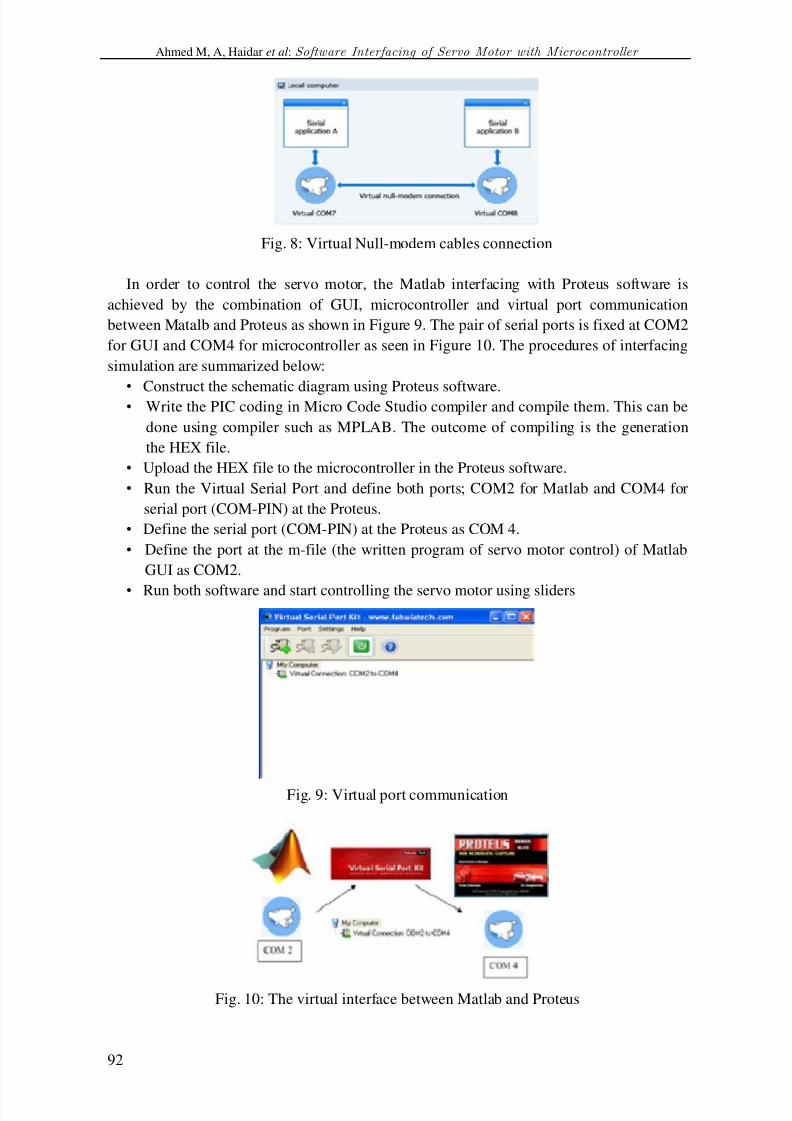
In order to control the servo motor, the Matlab interfacing with Proteus software is
achieved by the combination of GUI, microcontroller and virtual port communication
between Matalb and Proteus as shown in Figure 9. The pair of serial ports is fixed at COM2
for GUI and COM4 for microcontroller as seen in Figure 10. The procedures of interfacing
simulation are summarized below:
• Construct the schematic diagram using Proteus software.• Write the PIC coding in Micro Code Studio compiler and compile them. This can be
done using compiler such as MPLAB. The outcome of compiling is the generation
the HEX file.
• Upload the HEX file to the microcontroller in the Proteus software.
• Run the Virtual Serial Port and define both ports; COM2 for Matlab and COM4 for
serial port (COM-PIN) at the Proteus.
• Define the serial port (COM-PIN) at the Proteus as COM 4.
• Define the port at the m-file (the written program of servo motor control) of Matlab
GUI as COM2.
• Run both software and start controlling the servo motor using sliders
Fig. 9: Virtual port communication
Fig. 10: The virtual interface between Matlab and Proteus

8/15/2019 Jes Servo Paper
http://slidepdf.com/reader/full/jes-servo-paper 10/16
J. Electrical Systems 9-1 (2013): 84-99
93
Referring to the whole controlling system, the servo controller receives position
commands through a serial connection which can be provided by using one input/output
(I/O) pin of another microcontroller, or a PCs serial port. This pulse signal will cause the
shaft to locate itself at the midway position +/-90 degrees. The shaft rotation on a servo
motor is limited to approximately 180 degrees (+/-90 degrees from center position). A 1-ms
pulse will rotate the shaft all the way to the left, while a 2-ms pulse will turn the shaft all
the way to the right. By varying the pulse width between 1 and 2 ms, the servo motor shaft
can be rotated to any degree position within its range.
5. Hardware implementation of servo motor control
Figure 11 shows the schematic diagram of the controlling system, and the hardware of
this system is depicted in Figure 12. The application of MAX232 is used to regulate the
signal from PC to microcontroller during the interfacing process. The chip receives signals
-10V to +10V from PC for logic ‘0‘and ‘1’ and converts them into 0V and 5V in logic ‘0’
and ‘1’ for microcontroller in order to process the sending data . Serial port acts as a
medium for sending the data from PC to servo motor control circuit. This controlling
system is using the Integrated Circuit (IC) LM 7805 to regulate the 5V voltage supply to
entire circuit. A light-emitting diode (LED) is used as an indicator to determine the PWM
output generated by microcontroller and sent to the servo motor. The DC servo motor
utilized in this hardware is a Cytron RC Servo motor (C40R). The specification of this
motor is given in Table 1 [31]. PIC16F628A is the selected microcontroller chip to control
the speed of DC servo [25].
RS-232 is a standard for serial binary data signals connected between data terminal
equipment and data circuit terminating equipment [32]. According to this standard a logical"0" has a voltage level between -15V and -5V and a logical "1" has a level between +5V
and +15V. The microcontrollers use a 5V TTL-level (transistor-transistor logic) to transmit
signals. Therefore, the signals should be converted by using MAX232 that only needs a 5V
power supply to convert the signal from TTL-level to RS232 level and reverse. RS232 is a
serial interface that transfers the data bit by bit and requires only two single wires, one, to
send and another, to receive the data. Most of digital logic circuits and processors operate
with a “+5” volt. Usually the input circuit is unregulated power supply ranging from 9 volts
to 24 volts (DC). For this reason, LM 7805 is placed in the hardware and reacts as a
regulator to supply +5 volt [33].
Fig. 11: schematic diagram of the controlling system

8/15/2019 Jes Servo Paper
http://slidepdf.com/reader/full/jes-servo-paper 11/16
Ahmed M, A, Haidar et al: Software Interfacing of Servo Motor with Microcontroller
94
Fig. 12: Hardware of servo motor control
Table 1: Specification of the RC servo motor
Speed (s/60°) 0.19
Torque (Kg.cm) 6.00Pulse Width Range (ms) 0.546ms to 2.4ms
Weight (g) 38
Gear material Plastic
Servo type Standard
Input voltage (V) 5
The rotational angle of DC servo motor is measured manually using the protractor. One
of the blades will be marked as a reference point. The DC motor is placed at the centre of
the protractor and each movement of the slider in GUI Matalb will rotate the servo motorand the angle can be recorded. Figure 13 illustrates the measurement of angle, the
maximum and minimum values of angle in the slider are in the range of 0º to 180°. The
angle must be limited to 180°. For example, if the slider has a range of 90º to -60°, it means
that the measured value by the instrument in the range of maximum and minimum is 150º.
Fig. 13: Angle measurement
6. Result and discussion
The simulation is used to validate the results obtained from Proteus interfacing withMatlab GUI and with those found by the hardware interfacing in Matlab GUI. The GUI is
manually controlling the desired rotation angle of servo motor by the slider. Figure 14
8/15/2019 Jes Servo Paper
http://slidepdf.com/reader/full/jes-servo-paper 12/16
J. Electrical Systems 9-1 (2013): 84-99
95
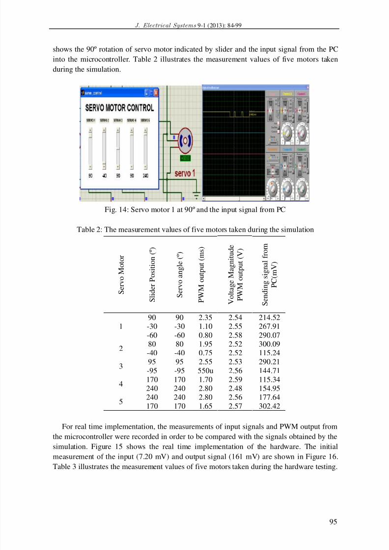
shows the 90º rotation of servo motor indicated by slider and the input signal from the PC
into the microcontroller. Table 2 illustrates the measurement values of five motors taken
during the simulation.
Fig. 14: Servo motor 1 at 90º and the input signal from PC
Table 2: The measurement values of five motors taken during the simulation
S e
r v o
M o
t o r
S l i d e
r P o s i t i o n
( º )
S e r v o a n g
l e ( º )
P W M
o u
t p u
t ( m s )
V o l t a g e
M a g n
i t u d e
P W M
o u
t p u
t ( V )
S e n d i n g s i g n a l
f r o m
P C ( m V )
1
90 90 2.35 2.54 214.52
-30 -30 1.10 2.55 267.91
-60 -60 0.80 2.58 290.07
280 80 1.95 2.52 300.09
-40 -40 0.75 2.52 115.24
395 95 2.55 2.53 290.21
-95 -95 550u 2.56 144.71
4
170 170 1.70 2.59 115.34
240 240 2.80 2.48 154.95
5240 240 2.80 2.56 177.64
170 170 1.65 2.57 302.42
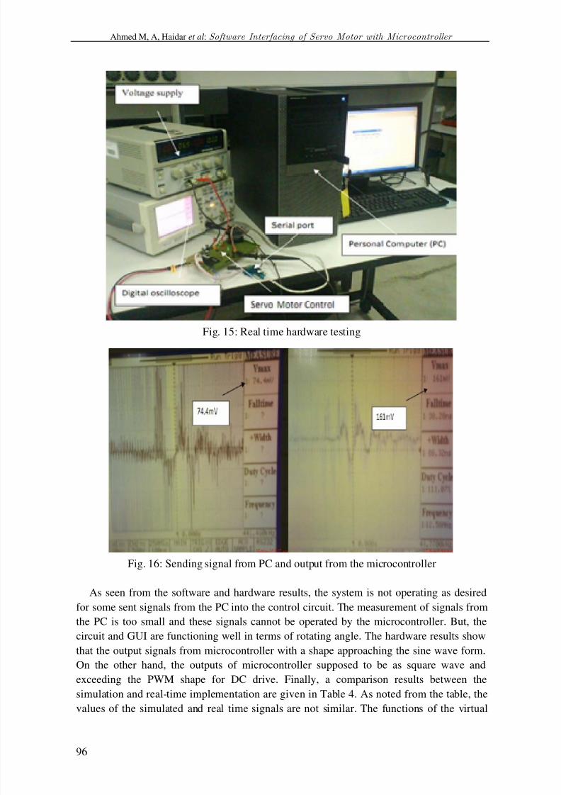
For real time implementation, the measurements of input signals and PWM output from
the microcontroller were recorded in order to be compared with the signals obtained by the
simulation. Figure 15 shows the real time implementation of the hardware. The initial
measurement of the input (7.20 mV) and output signal (161 mV) are shown in Figure 16.
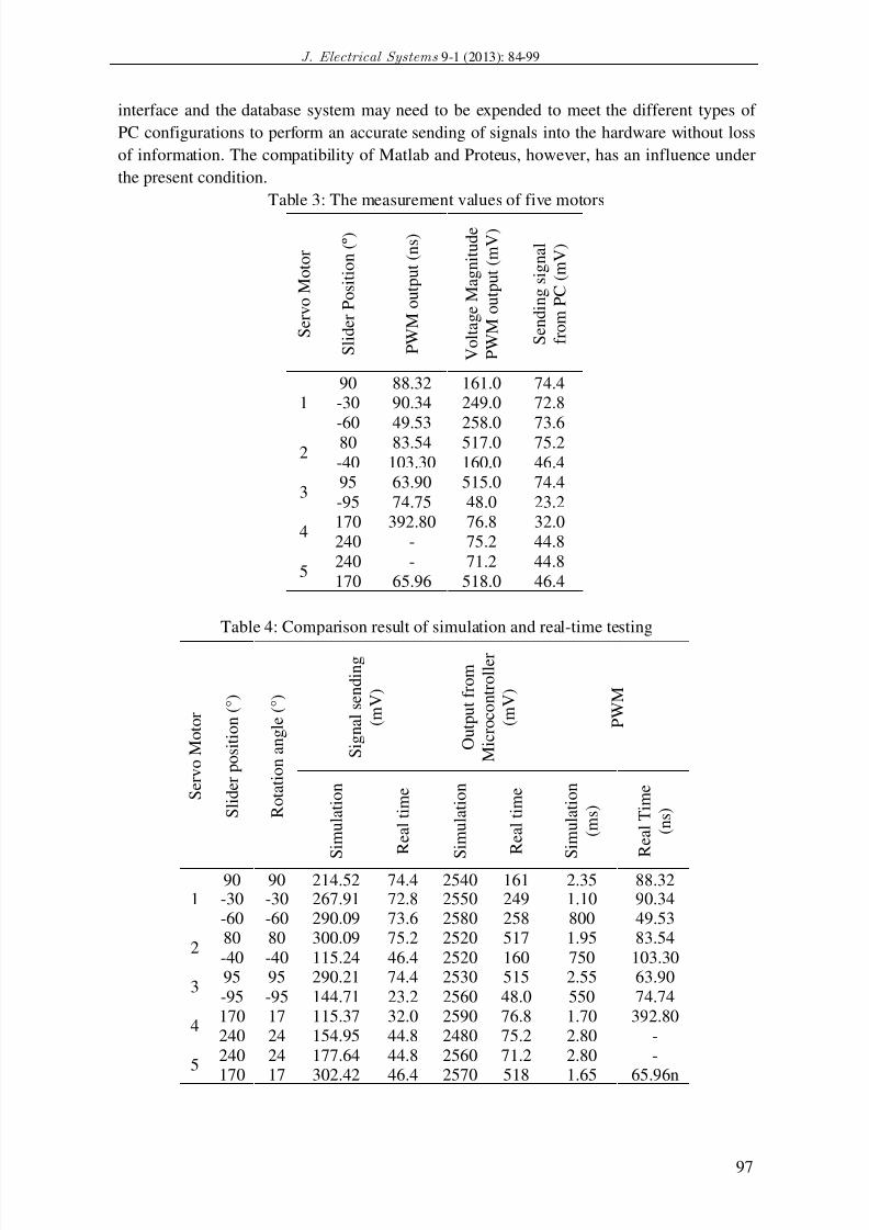
Table 3 illustrates the measurement values of five motors taken during the hardware testing.
8/15/2019 Jes Servo Paper
http://slidepdf.com/reader/full/jes-servo-paper 13/16
Ahmed M, A, Haidar et al: Software Interfacing of Servo Motor with Microcontroller
96
Fig. 15: Real time hardware testing
Fig. 16: Sending signal from PC and output from the microcontroller
As seen from the software and hardware results, the system is not operating as desired
for some sent signals from the PC into the control circuit. The measurement of signals from
the PC is too small and these signals cannot be operated by the microcontroller. But, the
circuit and GUI are functioning well in terms of rotating angle. The hardware results show
that the output signals from microcontroller with a shape approaching the sine wave form.
On the other hand, the outputs of microcontroller supposed to be as square wave and
exceeding the PWM shape for DC drive. Finally, a comparison results between the
simulation and real-time implementation are given in Table 4. As noted from the table, thevalues of the simulated and real time signals are not similar. The functions of the virtual
8/15/2019 Jes Servo Paper
http://slidepdf.com/reader/full/jes-servo-paper 14/16
J. Electrical Systems 9-1 (2013): 84-99
97
interface and the database system may need to be expended to meet the different types of
PC configurations to perform an accurate sending of signals into the hardware without loss
of information. The compatibility of Matlab and Proteus, however, has an influence under
the present condition.
Table 3: The measurement values of five motors
S e r v o
M o
t o r
S l i d e r
P o s i t i o n
( º )
P W M o u
t p u
t ( n s )
V o
l t a g e
M a g n
i t u d e
P W M o u
t p u
t ( m V )
S e n
d i n g s i g n a l
f r o m
P C ( m V )
190 88.32 161.0 74.4-30 90.34 249.0 72.8
-60 49.53 258.0 73.62
80 83.54 517.0 75.2
-40 103.30 160.0 46.4
395 63.90 515.0 74.4
-95 74.75 48.0 23.2
4170 392.80 76.8 32.0
240 - 75.2 44.8
5240 - 71.2 44.8
170 65.96 518.0 46.4
Table 4: Comparison result of simulation and real-time testing
S e r v o
M o
t o r
S l i d e r p o s i t i o n
( ° )
R o
t a t i o n a n g
l e ( ° )
S i g n a l s e n
d i n g
( m V )
O u
t p u
t f r o m
M i c r o c o n
t r o l l e r
( m V )
P W M
S i m u
l a t i o n
R e a l
t i m e
S i m u
l a t i o n
R e a l
t i m e
S i m u
l a t i o n
( m s )
R e a l
T i m e
( n s )
190 90 214.52 74.4 2540 161 2.35 88.32-30 -30 267.91 72.8 2550 249 1.10 90.34-60 -60 290.09 73.6 2580 258 800 49.53
280 80 300.09 75.2 2520 517 1.95 83.54
-40 -40 115.24 46.4 2520 160 750 103.30
395 95 290.21 74.4 2530 515 2.55 63.90
-95 -95 144.71 23.2 2560 48.0 550 74.74
4170 17 115.37 32.0 2590 76.8 1.70 392.80240 24 154.95 44.8 2480 75.2 2.80 -
5240 24 177.64 44.8 2560 71.2 2.80 -
170 17 302.42 46.4 2570 518 1.65 65.96n

8/15/2019 Jes Servo Paper
http://slidepdf.com/reader/full/jes-servo-paper 15/16
Ahmed M, A, Haidar et al: Software Interfacing of Servo Motor with Microcontroller
98
7. Conclusion
In this paper, microcontroller in Matlab GUI is proposed to control the desired position
of rotation angle using the GUI sliders. Based on the regulated values, the sliders control
the rotation of the servo motor. In real-time application, the sent data from PC is too small
and the microcontrollers are not passing enough signals to produce the actual desiredrotations. In order to improve the accuracy for real-time application, there is a need add
amplifier for increasing the signals from PC to the microcontroller. The major contribution
of this paper is the incorporation of two different softwares coding for real time control of a
servo motor rotation angle using GUI in Matlab.
References
[1] [006]K. Seki, H. Yokoi & M. Iwasaki, Experimental evaluations of friction behavior in micro-displacement
region positioning for servo motor with air bearings, Proceeding of IEEE International Conference on
Advanced Intelligent Mechatronics, 2012.
[2] [009] B. Li, L. Gao & G. Yang, Evaluation and compensation of steady gas flow force on the high pressureelectro-pneumatic servo valve direct-driven by voice coil motor, Energy Conversion and Management 67:92 – 102, 2013.
[3] K. N. D. Perera, S. R. M. Fernando, R. A. D. S Ranasinghe, A. U.S. & Ranathunga, P. K. Jayawardena,
Computer controlled DC servo motor, Working paper , pp1-3, 2003.[4] [007]R. Wai, & R. Muthusamy, Fuzzy-Neural-Network Inherited Sliding-Mode Control for Robot
Manipulator Including Actuator Dynamics, IEEE Transactions on Neural Networks and Learning Systems,
Vol. 24, NO. 2, 2013[5] M. J. Paytra & D. M. Mlynek, Fuzzy logic implementation and applications , Book. New York: John Wiley
Pres. p317, 1996.
[6] [004]B. Bossoufi, M. Karim, S. Ionita & A. Lagrioui1, Nonlinear non adaptive backstepping with sliding-mode torque control approach for PMSM motor, J. Electrical Systems 8-2: 236-248, 2012.
[7] [008]A. Sadeghieh, H. Sazgar, K. Goodarzi & C. Lucas, Identification and real-time position control of a
servo-hydraulic rotary actuator by means of a neurobiologically motivated algorithm, ISA Transactions 51:
208 – 219,2012.[8] [011] N. Yang, D. Li, J. Zhang & Y. Xi, Model predictive controller design and implementation on FPGA
with application to motor servo system, Control Engineering Practice 20 : 1229 – 1235, 2012.[9] [015]A. M. Al-Busaidi, Development of an educational environment for online control of a biped robot
using Matlab and Arduion, Proceeding of IEEE conference on Mecatronics-REM , 1-8, 2012.
[10] [014] J. Horng, Hybrid MATLAB and LabVIEW with neural network to implement a SCADA system of
AC servo motor, Advances in Engineering Software 39:149 – 155, 208.
[11] [016] N. Truong & D. Vu, “Hardware-in-the-Loop approach to the development and validation of precision
induction motor servo drive using xPC Target” Proceeding of Ninth International IEEE conference on
Computer Science and Software Engineering, 1-5, 2012.
[12] [017] L. Hongda1 & L. Fengxiang, experiment and Matlab simulation of electric power steering system
based on permanent magnet ac servo motor, Proceeding of IEEE International Conference on Computer
Science and Network Technology, 1-4, 2011.
[13] [012]S. Sharp, A. Wicks, A. Ordys & G. Collier, Modelling of a Pan and Tilt Servo System, Proceeding of IEEE International Conference on Control, 1-5, 2012.[14] [013]L. Xiaosheng, W. Yuqiang, H. Nantian & H. Yue, The Networked Virtual Test System for Servo
Motor and Drive Based on LabVIEW, Proceeding IEEE 7th international conference on Power Electronics
and Motion Control, 1-5, 2012.[15] C. C. Lee, Fuzzy logic in control systems: fuzzy logic controller-part1, IEEE Transaction System. Man.
Cybernetics., vo1.20 (no.2), pp.404-418, 1990.
[16] A. Mehmet, & T. Ismail, Motion controller design for the speed control of DC servo motor, International
Journal of Applied Mathematics And Informatics, Volume 1.(4):131-137, 2007.
[17] B. Tzeng, Y. C. Liu, M. S. Young, A preliminary study of fuzzy control parameters and Taguchi- method on
DC servo motor control, Proceeding of IEEE conference on Industrial Automation and Control: EmergingTechnologies, pp. 30-34,1995.
[18] [005] H. Yu, DSP-BASED Fuzzy Logic Servo Motor Control, Proceeding of IEEE International Conference
on Control Engineering and Communication Technology, 1-4, 2012.
[19] H.C, Pyung & W. L. Jeong, An observer design for time-delay control and its application to dc servo motor,Control Engineering Practice Journal, vol. 2, pp. 263-270, 1994.
8/15/2019 Jes Servo Paper
http://slidepdf.com/reader/full/jes-servo-paper 16/16
J. Electrical Systems 9-1 (2013): 84-99
99
[20] A. O. Dwyer, PID compensation of time delayed processes, Proceedings of the Irish Signals and Systems
Conference, Dublin, Ireland, June, pp. 5-12, 2000.
[21] [003]A. Abbou, T. Nasser, H. Mahmoudi, M. Akherraz & A. Essadki, dSPACE IFOC fuzzy logic controllerimplementation for induction motor drive, J. Electrical Systems 8-3 : 317-327, 2002.
[22] [002] P.Srinivas & P.V.N.Prasad, DSP based speed control of 4 phase 8/6 switched reluctance motor drive
using DC split converter, J. Electrical Systems 8-1: 47-56, 2002.[23] [001] A. Bouafia, J.P. Gaubert & A. Chaoui, Direct power control scheme based on disturbance rejection
principle for three-phase PWM AC/DC converter under different input voltage conditions, J. ElectricalSystems 8-4 : 367-383, 2012.
[24] K. N. Sae & S. Y. Wan, Fuzzy PID control with accelerated reasoning for dc servo motors, Journal of
Engineering Application Artificial Intelligent , Vol. 7, (No. 5), pp. 559-569, 1994.
[25] A. D. Lawrence, The microcontroller beginner’s handbook , (2nd Edition). United States of America: Prompt
Publication. P3-5,1998.
[26] R. Matt., Servo motor control application on a local interconnect network (LIN)”, Application Note Free
scale Semiconductor 8/16 Bit Division Systems Engineering Austin, Texas, Rev. 1.0., 2005.[27] V. George, 16 channel serial servo controller for robotic applications, Faculty of Technological
Applications, Technological Educational Institute of Piraeus, Greece retrieved from
http://www.seattlerobotics.org/encoder/200106/16csscnt.htm, August, 2010[28] M. Baron, B. Kocherov, Vision Guided Motor Control for Semi-Autonomous Military Vehicle, Final
Report, Institute Technology of Steven, 2007.
[29] Micromega Corporation, Controlling Lynx6RoboticArm, Website retrieved fromhttp://www.micromegacorp.com, September, 2009.
[30] Y. Y. Sergey, Parameter estimation and speed control of PMDC servo motor using method of time
moments, Sensors and Transducers Application Journal, Vol. 119, (Issue 8), pp162-173, 2010.[31] Y. Lee, J. Lee & S. Park, PID controller tuning for integrating and unstable processes with time delay,
Journal of Chemical Engineering Science, Vol. 55, pp. 3481-3493, 2000.
[32] Labcentre Electronic, Proteus design suite, product guide. Website retrieved from .http//www.labcenter.com,
August, 2011
[33] Fabula Tech LLP., Virtual Serial Port, Website. Retrieved from http://www.fabulatech.com/virtual-
serialport-kit , June, 2011.