Embed Size (px)
Citation preview

www.keithley.com
KPXI 48-Channel General Purpose Card
User’s ManualKPXI-DIO-900-01 Rev. A / January 2007
A G R E A T E R M E A S U R E O F C O N F I D E N C E
A G R E A T E R M E A S U R E O F C O N F I D E N C E
Keithley Instruments, Inc.
Corporate Headquarters • 28775 Aurora Road • Cleveland, Ohio 44139440-248-0400 • Fax: 440-248-6168 • 1-888-KEITHLEY (534-8453) • www.keithley.com
12/06
WARRANTYKeithley Instruments, Inc. warrants this product to be free from defects in material and workmanship for a period of 1 year from date of shipment.
Keithley Instruments, Inc. warrants the following items for 90 days from the date of shipment: probes, cables, rechargeable batteries, diskettes, and documentation.
During the warranty period, we will, at our option, either repair or replace any product that proves to be defective.
To exercise this warranty, write or call your local Keithley Instruments representative, or contact Keithley Instruments headquarters in Cleveland, Ohio. You will be given prompt assistance and return instructions. Send the product, transportation prepaid, to the indicated service facility. Repairs will be made and the product returned, transportation prepaid. Repaired or replaced products are warranted for the balance of the original warranty period, or at least 90 days.
LIMITATION OF WARRANTY
This warranty does not apply to defects resulting from product modification without Keithley Instruments’ express written consent, or misuse of any product or part. This warranty also does not apply to fuses, software, non-rechargeable batteries, damage from battery leakage, or problems arising from normal wear or failure to follow instructions.
THIS WARRANTY IS IN LIEU OF ALL OTHER WARRANTIES, EXPRESSED OR IMPLIED, INCLUDING ANY IMPLIED WARRANTY OF MERCHANTABILITY OR FITNESS FOR A PARTICULAR USE. THE REMEDIES PROVIDED HEREIN ARE BUYER’S SOLE AND EXCLUSIVE REMEDIES.
NEITHER KEITHLEY INSTRUMENTS, INC. NOR ANY OF ITS EMPLOYEES SHALL BE LIABLE FOR ANY DIRECT, INDIRECT, SPECIAL, INCIDENTAL OR CONSEQUENTIAL DAMAGES ARISING OUT OF THE USE OF ITS INSTRUMENTS AND SOFTWARE EVEN IF KEITHLEY INSTRUMENTS, INC., HAS BEEN ADVISED IN ADVANCE OF THE POSSIBILITY OF SUCH DAMAGES. SUCH EXCLUDED DAMAGES SHALL INCLUDE, BUT ARE NOT LIMITED TO: COSTS OF REMOVAL AND INSTALLATION, LOSSES SUSTAINED AS THE RESULT OF INJURY TO ANY PERSON, OR DAMAGE TO PROPERTY.
KPXI48-Channel General Purpose Card
User’s Manual
©2007, Keithley Instruments, Inc.All rights reserved.
Cleveland, Ohio, U.S.A.KPXI-DIO-900-01 Rev. A / January 2007Document Number:
Manual Print History KPXI 48-Channel General Purpose Card User’s Manual
All Keithley Instruments product names are trademarks or registered trademarks of Keithley Instruments, Inc.Other brand names are trademarks or registered trademarks of their respective holders.
KPXI-DIO-900-01 Rev. A / January 2007
Manual Print HistoryThe print history shown below lists the printing dates of all Revisions and Addenda created for this
manual. The Revision Level letter increases alphabetically as the manual undergoes subsequent updates. Addenda, which are released between Revisions, contain important change information that the user should incorporate immediately into the manual. Addenda are numbered sequentially. When a new Revision is created, all Addenda associated with the previous Revision of the manual are incorporated into the new Revision of the manual. Each new Revision includes a revised copy of this print history page.
Revision A (Document Number KPXI-DIO-900-01) ............................................ January 2007
Safety Precautions
The following safety precautions should be observed before using this product and any associated instrumentation. Although some instruments and accessories would normally be used with non-hazardous voltages, there are situations where hazardous conditions may be present.
This product is intended for use by qualified personnel who recognize shock hazards and are familiar with the safety precautions required to avoid possible injury. Read and follow all installation, operation, and maintenance information carefully before using the product. Refer to the manual for complete product specifications.
If the product is used in a manner not specified, the protection provided by the product may be impaired.
The types of product users are:
Responsible body is the individual or group responsible for the use and maintenance of equipment, for ensuring that the equipment is operated within its specifications and operating limits, and for ensuring that operators are adequately trained.
Operators use the product for its intended function. They must be trained in electrical safety procedures and proper use of the instrument. They must be protected from electric shock and contact with hazardous live circuits.
Maintenance personnel perform routine procedures on the product to keep it operating properly, for example, setting the line voltage or replacing consumable materials. Maintenance procedures are described in the manual. The procedures explicitly state if the operator may perform them. Otherwise, they should be performed only by service personnel.
Service personnel are trained to work on live circuits, and perform safe installations and repairs of products. Only properly trained service personnel may perform installation and service procedures.
Keithley Instruments products are designed for use with electrical signals that are rated Measurement Category I and Measurement Category II, as described in the International Electrotechnical Commission (IEC) Standard IEC 60664. Most measurement, control, and data I/O signals are Measurement Category I and must not be directly connected to mains voltage or to voltage sources with high transient over-voltages. Measurement Category II connections require protection for high transient over-voltages often associated with local AC mains connections. Assume all measurement, control, and data I/O connections are for connection to Category I sources unless otherwise marked or described in the Manual.
Exercise extreme caution when a shock hazard is present. Lethal voltage may be present on cable connector jacks or test fixtures. The American National Standards Institute (ANSI) states that a shock hazard exists when voltage levels greater than 30V RMS, 42.4V peak, or 60VDC are present. A good safety practice is to expect that hazardous voltage is present in any unknown circuit before measuring.
Operators of this product must be protected from electric shock at all times. The responsible body must ensure that operators are prevented access and/or insulated from every connection point. In some cases, connections must be exposed to potential human contact. Product operators in these circumstances must be trained to protect themselves from the risk of electric shock. If the circuit is capable of operating at or above 1000 volts, no conductive part of the circuit may be exposed.
Do not connect switching cards directly to unlimited power circuits. They are intended to be used with impedance limited sources. NEVER connect switching cards directly to AC mains. When connecting sources to switching cards, install protective devices to limit fault current and voltage to the card.
Before operating an instrument, make sure the line cord is connected to a properly grounded power receptacle. Inspect the connecting cables, test leads, and jumpers for possible wear, cracks, or breaks before each use.
12/06
When installing equipment where access to the main power cord is restricted, such as rack mounting, a separate main input power disconnect device must be provided, in close proximity to the equipment and within easy reach of the operator.
For maximum safety, do not touch the product, test cables, or any other instruments while power is applied to the circuit under test. ALWAYS remove power from the entire test system and discharge any capacitors before: connecting or disconnecting cables or jumpers, installing or removing switching cards, or making internal changes, such as installing or removing jumpers.
Do not touch any object that could provide a current path to the common side of the circuit under test or power line (earth) ground. Always make measurements with dry hands while standing on a dry, insulated surface capable of withstanding the voltage being measured.
The instrument and accessories must be used in accordance with its specifications and operating instructions or the safety of the equipment may be impaired.
Do not exceed the maximum signal levels of the instruments and accessories, as defined in the specifications and operating information, and as shown on the instrument or test fixture panels, or switching card.
When fuses are used in a product, replace with same type and rating for continued protection against fire hazard.
Chassis connections must only be used as shield connections for measuring circuits, NOT as safety earth ground connections.
If you are using a test fixture, keep the lid closed while power is applied to the device under test. Safe operation requires the use of a lid interlock.
If a screw is present, connect it to safety earth ground using the wire recommended in the user documentation.
The symbol on an instrument indicates that the user should refer to the operating instructions located in the manual.
The symbol on an instrument shows that it can source or measure 1000 volts or more, including the combined effect of normal and common mode voltages. Use standard safety precautions to avoid personal contact with these voltages.
The symbol on an instrument shows that the surface may be hot. Avoid personal contact to prevent burns.
The symbol indicates a connection terminal to the equipment frame.
The WARNING heading in a manual explains dangers that might result in personal injury or death. Always read the associated information very carefully before performing the indicated procedure.
The CAUTION heading in a manual explains hazards that could damage the instrument. Such damage may invalidate the warranty.
Instrumentation and accessories shall not be connected to humans.
Before performing any maintenance, disconnect the line cord and all test cables.
To maintain protection from electric shock and fire, replacement components in mains circuits, including the power transformer, test leads, and input jacks, must be purchased from Keithley Instruments. Standard fuses, with applicable national safety approvals, may be used if the rating and type are the same. Other components that are not safety related may be purchased from other suppliers as long as they are equivalent to the original component. (Note that selected parts should be purchased only through Keithley Instruments to maintain accuracy and functionality of the product.) If you are unsure about the applicability of a replacement component, call a Keithley Instruments office for information.
To clean an instrument, use a damp cloth or mild, water based cleaner. Clean the exterior of the instrument only. Do not apply cleaner directly to the instrument or allow liquids to enter or spill on the instrument. Products that consist of a circuit board with no case or chassis (e.g., data acquisition board for installation into a computer) should never require cleaning if handled according to instructions. If the board becomes contaminated and operation is affected, the board should be returned to the factory for proper cleaning/servicing.
!

Table of Contents
Section Topic Page
1 Introduction............................................................................................. 1-1Introduction ................................................................................................. 1-2
Features ............................................................................................... 1-2Applications.......................................................................................... 1-2
Safety symbols and terms .......................................................................... 1-2Specifications.............................................................................................. 1-3Unpacking and inspection........................................................................... 1-3
Inspection for damage.......................................................................... 1-3Shipment contents ............................................................................... 1-3Instruction manual................................................................................ 1-3Repacking for shipment........................................................................ 1-4
Supporting software.................................................................................... 1-4Programming library KDIO-DRVR........................................................ 1-4KDAQ-LVIEW LabVIEW® driver .......................................................... 1-4
2 Installation ............................................................................................... 2-1Introduction ................................................................................................. 2-2Handling precautions .................................................................................. 2-2PXI configuration ........................................................................................ 2-2
Plug and play ....................................................................................... 2-2Configuration........................................................................................ 2-2Troubleshooting.................................................................................... 2-2
Installation................................................................................................... 2-3Jumper description ..................................................................................... 2-5Termination boards connection................................................................... 2-6PCB layout.................................................................................................. 2-7
3 Operation and Connection .................................................................. 3-1Digital I/O ports ........................................................................................... 3-2
Introduction ......................................................................................... 3-28255 Mode 0 ........................................................................................ 3-2Special function of the DIO signals ..................................................... 3-2Digital I/O port programming ............................................................... 3-2Control word......................................................................................... 3-2Power on configuration ....................................................................... 3-3Output data concern............................................................................. 3-4
Timer/counter operation.............................................................................. 3-4Introduction ......................................................................................... 3-4General purpose timer/counter ............................................................ 3-4Cascaded 32 Bits Timer ..................................................................... 3-5Event counter and edge control ........................................................... 3-5
Interrupt multiplexing .................................................................................. 3-5Architecture .......................................................................................... 3-5IRQ level setting................................................................................... 3-5Dual interrupts concerns ...................................................................... 3-6Interrupt source control ........................................................................ 3-6
12V and 5V power supply ......................................................................... 3-7Connector pin assignment .......................................................................... 3-7
Pin assignment of Model KPXI-DIO-48................................................ 3-7
Table of Contents KPXI 48-Channel General Purpose Card User’s Manual
Section Topic Page
4 Registers .................................................................................................. 4-1Introduction ................................................................................................. 4-2
PCI PnP registers ................................................................................. 4-2I/O address map ................................................................................... 4-2
Appendix Topic Page
A KDIO-DRVR User’s Guide ................................................................... A-1Introduction to KDIO-DRVR ....................................................................... A-2
About the KDIO-DRVR software.......................................................... A-2KDIO-DRVR hardware support............................................................ A-2KDIO-DRVR language support............................................................ A-2
KDIO-DRVR overview................................................................................ A-3General configuration function group .................................................. A-3Actual sampling rate function group .................................................... A-4Analog output function group............................................................... A-4Digital input function group .................................................................. A-4Digital output function group ................................................................ A-6Timer/counter function group............................................................... A-7DIO function group .............................................................................. A-8
Creating a KDIO-DRVR application ........................................................... A-9Contiguous memory allocation in driver for continuous operation....... A-9
Fundamentals of building Windows XP/2000 Application .......................... A-9Microsoft® Visual Basic (Version 6.0) .................................................. A-9Using Microsoft Visual Basic.NET ...................................................... A-11Microsoft Visual C/C++ ....................................................................... A-11
KDIO-DRVR application hints ................................................................... A-11Digital input programming hints ......................................................... A-12Digital output programming hints ....................................................... A-17DAQ event message programming hints........................................... A-21Interrupt event message programming hints ..................................... A-22
Continuous data transfer in KDIO-DRVR................................................. A-23Continuous data transfer mechanism................................................ A-23Double-buffered / multiple-buffered DI operation............................... A-23
KDIO-DRVR utilities for Win32................................................................. A-25KDIO-DRVR configuration utility (configdrv)...................................... A-25KDIO-DRVR data file converter utility (KIDAQCvt)............................ A-26
B KDIO-DRVR Function Reference ....................................................... B-1Function description ................................................................................... B-2
Data types............................................................................................ B-2Function reference............................................................................... B-2
Status Codes............................................................................................ B-38Data file format......................................................................................... B-40
Header............................................................................................... B-40ChannelRange................................................................................... B-41Data Block ......................................................................................... B-42
Function Support...................................................................................... B-43
C KIDAQ®-LabVIEW Compatible Interface Guide............................. C-1Introduction to KIDAQ®-LabVIEW ............................................................. C-2
Overview.............................................................................................. C-2Using KIDAQ LabVIEW VIs in LabVIEW............................................. C-2KIDAQ LabVIEW Programming........................................................... C-3
Device Driver Handling .............................................................................. C-4Windows XP/2000 Device Driver......................................................... C-4Driver Utility ......................................................................................... C-4
KIDAQ Utilities ........................................................................................... C-4KIDAQ Registry/Configuration utility.................................................... C-4
ii KPXI-DIO-900-01 Rev. A / January 2007
KPXI 48-Channel General Purpose Card User’s Manual Table of Contents
KP
Appendix Topic Page
C KIDAQ®-LabVIEW Compatible Interface Guide (continued)
KIDAQ Device Browser ....................................................................... C-4KIDAQ LabVIEW VIs Overview.................................................................. C-5
Analog Input VIs .................................................................................. C-6Analog Output VIs................................................................................ C-6Digital I/O VIs....................................................................................... C-7Timer/Counter VIs................................................................................ C-7Calibration and Configuration VIs ........................................................ C-8Error Handler VI................................................................................... C-8
Distribution of Applications......................................................................... C-8Windows XP/2000 ............................................................................... C-8
D KIDAQ®-LabVIEW Compatible Function Reference..................... D-1Introduction ................................................................................................ D-2Hardware support....................................................................................... D-2
KPXI-DIO series: ................................................................................. D-2KPXI-DAQ series: ................................................................................ D-2Digitizer series: .................................................................................... D-2
Analog input VIs ......................................................................................... D-3Easy analog input VIs .......................................................................... D-3Intermediate analog input VIs .............................................................. D-7
Analog output VIs..................................................................................... D-21Easy analog output VIs...................................................................... D-21Intermediate analog output VIs.......................................................... D-24Advanced analog output VIs.............................................................. D-32
Digital I/O VIs ........................................................................................... D-33Easy Digital I/O VIs............................................................................ D-33Intermediate Digital I/O VIs................................................................ D-37Advanced Digital I/O VIs.................................................................... D-45
Counter VIs .............................................................................................. D-46Easy Counter VIs .............................................................................. D-46Intermediate Counter VIs .................................................................. D-50Advanced Counter VIs ...................................................................... D-63
Calibration and Configuration VIs ............................................................ D-67Calibration VIs .................................................................................. D-67Other Calibration and Configuration VIs ............................................ D-68
Service VIs ............................................................................................... D-70Error Codes ............................................................................................. D-71AI Range Codes ...................................................................................... D-73AI Data Format ....................................................................................... D-76
Service Form
XI-DIO-900-01 Rev. A / January 2007 iii

Table of Contents KPXI 48-Channel General Purpose Card User’s Manual
This page left blank intentionally.
iv KPXI-DIO-900-01 Rev. A / January 2007
List of Figures
Section Figure Title Page
2 Figure 2-1 Typical PXI module installation ...................................................... 2-4Figure 2-2 Device manager (successful installation) ...................................... 2-5Figure 2-3 Model KPXI-DIO-48 PCB Layout................................................... 2-7
3 Figure 3-1 Control Word Format .................................................................... 3-3Figure 3-2 Timer/counter system of Model KPXI-DIO-48................................ 3-4Figure 3-3 Dual Interrupt System Model KPXI-DIO-48 ................................... 3-5
Appendix Figure Title Page
A Figure A-1 Open Project dialog box .............................................................. A-10Figure A-2 Basic KDIO-DRVR building blocks .............................................. A-12Figure A-3 One-shot digital input programming............................................. A-13Figure A-4 Synchronous continuous digital input programming .................... A-14Figure A-5 Non-multiple-buffered asynchronous continuous digital input ..... A-15Figure A-6 Multiple-buffered asynchronous continuous digital input ............. A-16Figure A-7 Synchronous continuous digital output programming.................. A-18Figure A-8 Asynchronous continuous digital output programming ................ A-18Figure A-9 Pattern generation digital output programming ........................... A-19Figure A-10 Multiple-buffered asynchronous continuous digital output ........... A-20Figure A-11 Double/multiple buffer mode principle ......................................... A-24Figure A-12 Driver configuration window......................................................... A-25Figure A-13 DAQ File Conversion Utility ......................................................... A-26Figure A-14 Loading source binary data file .................................................... A-27
B Figure B-1 TOGGLE_OUTPUT mode timing .................................................. B-4Figure B-2 PROG_ONE_SHOT mode timing.................................................. B-4Figure B-3 RATE_GENERATOR mode timing ................................................ B-5Figure B-4 SQ_WAVE_RATE_GENERATOR mode timing ............................. B-5Figure B-5 SOFT_TRIG mode timing .............................................................. B-5Figure B-6 HARD_TRIG mode timing ............................................................. B-5Figure B-7 DAQ File Conversion Utility ......................................................... B-42
C Figure C-1 Function Browser Options ............................................................. C-2Figure C-2 Functions palette ........................................................................... C-3Figure C-3 Keithley PXI Devices Explorer ....................................................... C-5
D Figure D-1 Analog input palette ....................................................................... D-3Figure D-2 Analog output palette................................................................... D-21Figure D-3 Digital I/O palette ......................................................................... D-33

List of Figures KPXI 48-Channel General Purpose Card User’s Manual
This page left blank intentionally.
vi KPXI-DIO-900-01 Rev. A / January 2007
List of Tables
Section Table Title Page
2 Table 2-1 Jumpers and Port names list ......................................................... 2-5Table 2-2 JA1 jumper setting ......................................................................... 2-6Table 2-3 JP1 12V Power Supply Configuration........................................... 2-6
3 Table 3-1 I/O Port Names .............................................................................. 3-2Table 3-2 Summary of control word (D0 - D4) ............................................... 3-3Table 3-3 ISC register format......................................................................... 3-6Table 3-4 IRQ Trigger conditions ................................................................... 3-6Table 3-5 Pinout and power signals of Model KPXI-DIO-48.......................... 3-7
4 Table 4-1 Model KPXI-DIO-48 I/O Address Map ........................................... 4-2
Appendix Table Title Page
B Table B-1 Suggested data types .................................................................... B-2Table B-2 Channel_Pn data format.............................................................. B-16Table B-3 Status codes returned by KDIO-DRVR........................................ B-38Table B-4 Data file header ........................................................................... B-40Table B-5 Data structure of ChannelRange unit .......................................... B-41Table B-6 KDIO-DRVR model function ........................................................ B-43
D Table D-1 KI AI acquire waveform.................................................................. D-3Table D-2 KI AI acquire waveforms................................................................ D-4Table D-3 KI AI sample channel..................................................................... D-6Table D-4 KI AI sample channels ................................................................... D-6Table D-5 KI AI clear ...................................................................................... D-7Table D-6 KI AI config .................................................................................... D-9Table D-7 2-byte binary array....................................................................... D-12Table D-8 Scaled and Binary Arrays ............................................................ D-14Table D-9 Scaled Array ................................................................................ D-16Table D-10 KI AI single scan .......................................................................... D-17Table D-11 KI AI start ..................................................................................... D-19Table D-12 KI AO generate waveform ........................................................... D-22Table D-13 KI AO generate waveforms.......................................................... D-22Table D-14 KI AO update channel.................................................................. D-23Table D-15 KI AO update channels................................................................ D-24Table D-16 KI AO clear .................................................................................. D-25Table D-17 KI AO Config................................................................................ D-25Table D-18 KI AO start ................................................................................... D-27Table D-19 KI AO wait.................................................................................... D-28Table D-20 KI AO write binary array............................................................... D-29Table D-21 KI AO write binary array scaled array .......................................... D-30Table D-22 KI AO Trigger and Gate Config.................................................... D-32Table D-23 KI Read from Digital Line............................................................. D-34Table D-24 KI Read from Digital Port ............................................................. D-34
List of Tables KPXI 48-Channel General Purpose Card User’s Manual
Appendix Table Title Page
D Table D-25 KI Write to Digital Line................................................................. D-35Table D-26 KI Write to Digital Port ................................................................. D-36Table D-27 KI DIO Clear................................................................................ D-37Table D-28 KI DIO Config .............................................................................. D-38Table D-29 KI DIO Read................................................................................ D-40Table D-30 KI DIO Start ................................................................................. D-42Table D-31 KI DIO Write ................................................................................ D-43Table D-32 KI DIO Port Config ...................................................................... D-45Table D-33 KI Count Events or Time ............................................................. D-46Table D-34 KI Generate Delayed Pulse......................................................... D-47Table D-35 KI Generate Pulse-Train.............................................................. D-48Table D-36 KI Measure Pulse-Width or Period.............................................. D-49Table D-37 KI Continuous Pulse Generator Config ....................................... D-50Table D-38 KI Counter Divider Config ........................................................... D-52Table D-39 KI Counter Read ......................................................................... D-53Table D-40 KI Counter Start........................................................................... D-54Table D-41 KI Counter Stop........................................................................... D-55Table D-42 KI Delayed Pulse Generator Config ............................................ D-56Table D-43 KI Down Counter or Divider Config ............................................. D-58Table D-44 KI Event or Time Counter Config ................................................ D-59Table D-45 KI Pulse-Width or Period Measurement Config .......................... D-61Table D-46 KI UpDown Counter Config......................................................... D-62Table D-47 KI ICTR Control........................................................................... D-63Table D-48 KI KPXI-DAQ series devices and Digitizer Series Calibrate ...... D-67Table D-49 KI Route Signal .......................................................................... D-68Table D-50 KI SSI Control ............................................................................ D-69Table D-51 KI Error Handler ......................................................................... D-70Table D-52 Error Codes: KIDAQ LabVIEW VIs ............................................. D-71Table D-53 Analog Input Range .................................................................... D-73Table D-54 Valid analog input ranges (specified by module)......................... D-75Table D-55 Analog Input data format (by Model) ........................................... D-76
viii KPXI-DIO-900-01 Rev. A / January 2007
Section 1 Introduction
In this section:
Topic Page
Introduction......................................................................................... 1-2Features ........................................................................................... 1-2Applications ...................................................................................... 1-2
Safety symbols and terms .............................................................. 1-2
Specifications ..................................................................................... 1-3
Unpacking and inspection .............................................................. 1-3Inspection for damage ...................................................................... 1-3Shipment contents ............................................................................ 1-3Instruction manual ............................................................................ 1-3Repacking for shipment .................................................................... 1-4
Supporting software ......................................................................... 1-4Programming library KDIO-DRVR .................................................... 1-4KDAQ-LVIEW LabVIEW® driver....................................................... 1-4
Section 1: Introduction KPXI 48-Channel General Purpose Card User’s Manual
IntroductionThe Model KPXI-DIO-48 is a general purpose, 48 channel digital input / output (DIO) product. The KPXI-DIO-48 emulates two industry standard Programmable Peripheral Interface (PPI) chips operated under mode zero configuration. The cards are compatible in hardware connections as well as software programming.
Each PPI connector has 3 ports: PA, PB, and PC. The PC can also be subdivided into 2 nibble-wide (4-bit) ports - PC Upper and PC Low. Each connector is corresponding to one PPI chip with 24 DIO points. The Model KPXI-DIO-48 is equipped with one 100-pin SCSI-type connector.
FeaturesModel KPXI-DIO-48 products provide the following advanced features:
Digital I/O ports• 48 TTL/DTL compatible digital I/O lines• Emulates industry standard mode 0 of 8255 PPI• Buffered circuits for higher driving• Output status read-back
Timer/counter and interrupt system • A 32 bit timer to generate watchdog timer interrupt• A 16 bit event counter to generate event interrupt• Programmable interrupt source• Dual interrupt system
Miscellaneous• On board fuses that can be reset protect the power supply from external devices
Applications• Programmable mixed digital input & output • Industrial monitoring and control• Digital I/O control• Contact closure, switch/keyboard monitoring• Useful with A/D and D/A to implement a data acquisition & control system
Safety symbols and termsThe following symbols and terms may be found on the KPXI DIO series module or used in this manual.
The symbol indicates that the user should refer to the operating instructions located in the manual.
The symbol shows that high voltage may be present on the terminal(s). Use standard safety precautions to avoid personal contact with these voltages.
The symbol on an instrument shows that the surface may be hot. Avoid personal contact to prevent burns.
!
1-2 Return to Section Topics KPXI-DIO-900-01 Rev. A / January 2007
KP
KPXI 48-Channel General Purpose Card User’s Manual Section 1: Introduction
The WARNING heading used in this manual explains dangers that might result in personal injury or death. Always read the associated information very carefully before performing the indicated procedure.
The CAUTION heading used in this manual explains hazards that could damage the unit. Such damage may invalidate the warranty.
SpecificationsRefer to the product data sheet for updated KPXI DIO card specifications. Check the Keithley Instruments website at www.keithley.com for the latest updates to the specifications.
Unpacking and inspection
Inspection for damage
CAUTION Your KPXI DIO series module contains electro-static sensitive components that can be easily be damaged by static electricity.
Therefore, handle the card on a grounded anti-static mat. The operator should be wearing an anti-static wristband, grounded at the same point as the antistatic mat.
The KPXI General Purpose DIO series module was carefully inspected electrically and mechanically before shipment.
Inspect the module carton for obvious damages. Shipping and handling may damage the module. Make sure there are no shipping and handling damages on the module’s carton before continuing.
After opening the card module carton, extract the system module and place it only on a grounded anti-static surface with component side up. Save the original packing carton for possible future shipment.
Again, inspect the module for damages. Report any damage to the shipping agent immediately.
Shipment contentsThe following items are included with every Model KPXI DIO series order:
• Model KPXI DIO series module• CD containing required software and manuals
Instruction manualA CD-ROM containing this User’s Manual and required software is included with each Model KPXI General Purpose DIO series order. If a hardcopy of the Model KPXI-DIO Series User’s Manual is required, you can order the Manual Package (Keithley Instruments Part Number Model KPXI-DIO-900-01). The Manual Package includes an instruction manual and any pertinent addenda.
Always check the Keithley Instruments’ website at www.keithley.com for the latest revision of the manual. The latest manual can be downloaded (in PDF format) from the website.
XI-DIO-900-01 Rev. A / January 2007 Return to Section Topics 1-3
Section 1: Introduction KPXI 48-Channel General Purpose Card User’s Manual
Repacking for shipment Should it become necessary to return the Model KPXI General Purpose DIO series module for repair, carefully pack the unit in its original packing carton or the equivalent, and follow these instructions:
• Call Keithley Instruments’ repair department at 1-888-KEITHLEY (1-888-534-8453) for a Return Material Authorization (RMA) number.
• Let the repair department know the warranty status of the Model KPXI General Purpose DIO series module.
• Write ATTENTION REPAIR DEPARTMENT and the RMA number on the shipping label.• Complete and include the Service Form located at the back of this manual.
Supporting software This section contains information on provided software. Keithley Instruments’ provides versatile software drivers and packages for different systems. Keithley Instruments not only provides programming libraries such as DLL’s for most Windows® based systems, but also drivers for other software packages such as LabVIEW.1
All software options are included in the Keithley Instruments’ CD.
Programming library KDIO-DRVRKDIO-DRVR includes device drivers and DLL’s for Windows XP® and Windows 2000®. Therefore, all applications developed with KDAQ-DRVR are compatible on Windows XP/2000. The developing environment can be VB, VC++, BC5, or any Windows programming language that allows calls to a DLL. Documentation includes a User's Guide (refer to Appendix A: KDIO-DRVR User’s Guide), and a Function Reference (refer to Appendix B: KDIO-DRVR Function Reference).
KDAQ-LVIEW LabVIEW® driverKDAQ-LVIEW contains the VI’s, which are used to interface with National Instrument's Lab-VIEW® software package. The KDAQ-LVIEW supports Windows XP/2000. The LabVIEW® driver is shipped free with the board — you can install and use them without a license. Documentation includes an Interface Guide (refer to Appendix C: KIDAQ®-LabVIEW Compatible Interface Guide), and an interface Function Reference (refer to Appendix D: KIDAQ®-LabVIEW Compatible Function Reference).
1. National Instruments™, NI, and LabVIEW are trademarks of the National Instruments Corporation.
1-4 Return to Section Topics KPXI-DIO-900-01 Rev. A / January 2007
Section 2 Installation
In this section:
Topic Page
Introduction......................................................................................... 2-2
Handling precautions ....................................................................... 2-2
PXI configuration ............................................................................... 2-2Plug and play.................................................................................... 2-2Configuration .................................................................................... 2-2Troubleshooting ................................................................................ 2-2
Installation ........................................................................................... 2-3
Jumper description ........................................................................... 2-5
Termination boards connection..................................................... 2-6
PCB layout........................................................................................... 2-7
Section 2: Installation KPXI 48-Channel General Purpose Card User’s Manual
IntroductionThis section contains information about handling and installing Keithley Instruments’ KPXI series cards:
• Handling precautions• PXI configuration• Installation• Jumper description• Termination boards connection• PCB layout
Handling precautionsCAUTION Use care when handling the KIDAQ® KPXI series cards. KIDAQ® KPXI series
cards contain electro-static sensitive components that can be easily damaged by static electricity.
When handling, make sure to observe the following guidelines:
• Only handle the card on a grounded anti-static mat.• Wear an an anti-static wristband that is grounded at the same point as the anti-static mat.
PXI configuration
Plug and playAs a plug and play component, the board requests an interrupt number via its cPCI controller. The system BIOS responds with an interrupt assignment based on the board information and system parameters. These system parameters are determined by the installed drivers and the hardware load recognized by the system. If this is the first time a KIDAQ® KPXI series card will be installed on your Windows® system, a hardware driver needs to be installed. Refer to Installation for detailed information.
ConfigurationConfiguration is done on a board-by-board basis for all PCI boards on your system. Configuration is controlled by the system and software. There is no jumper setting required (or available) for base address, DMA, and interrupt IRQ.
The configuration is not static, but is subject to change with every boot of the system as new boards are added or removed.
TroubleshootingIf your system doesn't boot or if you experience erratic operation with your PCI board in place, it's likely caused by an interrupt conflict (perhaps the BIOS Setup is incorrectly configured). In general, the solution, is to consult the BIOS documentation that came with your system.
2-2 Return to Section Topics KPXI-DIO-900-01 Rev. A / January 2007
KP
KPXI 48-Channel General Purpose Card User’s Manual Section 2: Installation
Installation
Step 1. Install driver softwareWindows® will find the new module automatically. If this is the first time a KPXI series digital I/O card has been installed, a hardware driver needs to be installed. Use the following installation procedure as a guide.
NOTE Keithley Instruments controllers are pre-loaded with the necessary drivers.
For Windows XP/2000:
1. Insert the CD shipped with the module. The CD should auto load. From the base menu install the KDIO-DRVR. This is the hardware driver that recognizes the KPXI series modules. If the CD does not auto load run, then under x:\KDIO-DRVR\DISK1\, you will find SETUP.EXE (x is the drive letter of your CDROM). This will run the CD menu. On the CD menu, click the driver for your model to install.
2. When you complete driver installation, turn off the system.
Step 2. Inspect moduleKeeping the “Handling precautions” information in mind, inspect the module for damage. With the module placed on a firm flat surface, press down on all socketed IC's to make sure that they are properly seated.
If the module does not pass the inspection, do not proceed with the installation.
CAUTION Do not apply power to the card if it has been damaged.
The card is now ready for installation.
Step 3. Install moduleRemove power from the system and install the KPXI card in an available slot.
The PXI connectors are rigid and require careful handling when inserted and removed. Improper handling of modules can easily damage the backplane.
To insert the module into a PXI chassis, use the following procedure as a guide:
1. Read through this manual and setup required jumpers (as needed). Refer to Jumper description for additional information.
2. Turn off the system. 3. Align the module's edge with the card guide in the PXI chassis. 4. Slide the module into the chassis until resistance is felt from the PXI connector. 5. Push the ejector upwards and fully insert the module into the chassis. Once inserted, a
"click" can be heard from the ejector latch. 6. Tighten the screw on the front panel. 7. Turn on the system.
To remove a module from a PXI chassis, use the following procedure as a guide:
1. Turn off the system. 2. Loosen the screw on the front panel. 3. Push the ejector downwards and carefully remove the module from the chassis.
XI-DIO-900-01 Rev. A / January 2007 Return to Section Topics 2-3
Section 2: Installation KPXI 48-Channel General Purpose Card User’s Manual
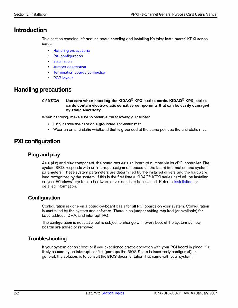
Figure 2-1Typical PXI module installation
Step 4. Verify installationWhen the system is turned on for the first time with a new module present (or a module in a new slot), Windows Add New Hardware Wizard attempts to locate the correct driver. If it cannot find the correct driver, even after you have loaded the driver above in Step 1, then force the Add New Hardware Wizard to look in Windows system32 directory. The driver files should be in this location. If they are not, shutdown the system, remove the module, and restart the installation process.
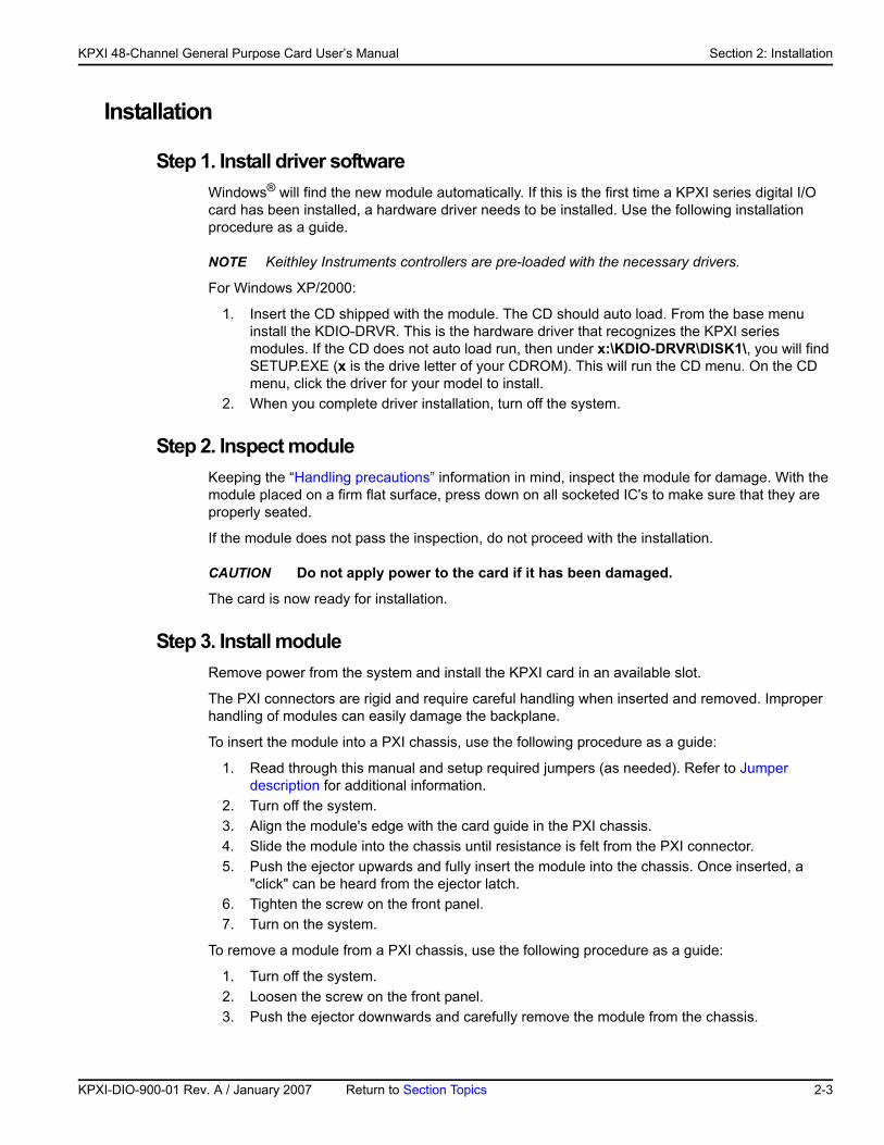
When the Add New Hardware Wizard finishes, the window will verify whether or not installation was successful. To confirm if the module is installed correctly at a later time, use Windows Device Manager. In the Device Manager under KIDAQ Boards, look for a device name matching the model number of the newly installed board (see Figure 2-2 for an example). If it is found, installation is complete. If the board appears with a exclamation point or warning in Device Manager, the installation was unsuccessful. If unsuccessful, use Device Manager to update the
������������
���������
���������
�����������
�����������������
2-4 Return to Section Topics KPXI-DIO-900-01 Rev. A / January 2007
KP
KPXI 48-Channel General Purpose Card User’s Manual Section 2: Installation
driver or un-install the module, power down the system, remove the module, and attempt installation again from Step 1.
Figure 2-2Device manager (successful installation)
Jumper descriptionModel KPXI-DIO-48 DIO cards are plug-and-play, which makes it unnecessary to setup the card configurations to fit the computer system. However, to fit users’ versatile operation environment, there are still a few jumpers to set the power-on status of ports and the usage of the +12V output pin.
Power on Status of PortsFor every port on a Model KPXI-DIO-48 card, the power-on status is set as input, therefore, the voltage could be pulled high, pulled low, or floating. It is dependent on the jumper setting. Table 2-1 lists jumper reference numbers and corresponding port names.
Table 2-1Jumpers and Port names list
Jumper Port NameJA1 P1A (Port A of PPI1)JB1 P1B (Port B of PPI1)JC1 P1C (Port C of PPI1)JA2 P2A (Port A of PPI2)JB2 P2B (Port B of PPI2)JC2 P2C (Port C of PPI2)
XI-DIO-900-01 Rev. A / January 2007 Return to Section Topics 2-5
Section 2: Installation KPXI 48-Channel General Purpose Card User’s Manual
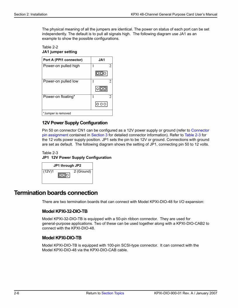
The physical meaning of all the jumpers are identical. The power on status of each port can be set independently. The default is to pull all signals high. The following diagram use JA1 as an example to show the possible configurations.
12V Power Supply ConfigurationPin 50 on connector CN1 can be configured as a 12V power supply or ground (refer to Connector pin assignment contained in Section 3 for detalied connector information). Refer to Table 2-3 for the 12 volts power supply position. JP1 sets the pin to be 12V or ground. Connections with ground are set as default. The following diagram shows the setting of JP1, connecting pin 50 to 12 volts.
Termination boards connectionThere are two termination boards that can connect with Model KPXI-DIO-48 for I/O expansion:
Model KPXI-32-DIO-TBModel KPXI-32-DIO-TB is equipped with a 50-pin ribbon connector. They are used for general-purpose applications. Two of these can be used together along with a KPXI-DIO-CAB2 to connect with the KPXI-DIO-48.
Model KPXI-DIO-TBModel KPXI-DIO-TB is equipped with 100-pin SCSI-type connector. It can connect with the Model KPXI-DIO-48 via the KPXI-DIO-CAB cable.
Table 2-2JA1 jumper setting
Port A (PPI1 connector) JA1
Power-on pulled high 1 2
Power-on pulled low 1 2
Power-on floating* 1 2
*Jumper is removed
Table 2-3JP1 12V Power Supply Configuration
JP1 through JP2(12V)1 2 (Ground)
2-6 Return to Section Topics KPXI-DIO-900-01 Rev. A / January 2007
KP
KPXI 48-Channel General Purpose Card User’s Manual Section 2: Installation
PCB layout
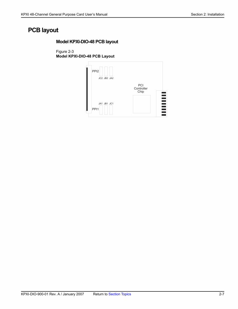
Model KPXI-DIO-48 PCB layout
Figure 2-3Model KPXI-DIO-48 PCB Layout
����
��������������
��� � �
����
�!�
�!� � � ���
XI-DIO-900-01 Rev. A / January 2007 Return to Section Topics 2-7

Section 2: Installation KPXI 48-Channel General Purpose Card User’s Manual
This page left blank intentionally.
2-8 Return to Section Topics KPXI-DIO-900-01 Rev. A / January 2007
Section 3 Operation and Connection
In this section:
Topic Page
Digital I/O ports................................................................................... 3-2Introduction ...................................................................................... 3-28255 Mode 0..................................................................................... 3-2Special function of the DIO signals .................................................. 3-2Digital I/O port programming ............................................................ 3-2Control word ..................................................................................... 3-2Power on configuration .................................................................... 3-3Output data concern ......................................................................... 3-4
Timer/counter operation .................................................................. 3-4Introduction ...................................................................................... 3-4General purpose timer/counter ......................................................... 3-4Cascaded 32 Bits Timer .................................................................. 3-5Event counter and edge control........................................................ 3-5
Interrupt multiplexing ....................................................................... 3-5Architecture ...................................................................................... 3-5IRQ level setting ............................................................................... 3-5Dual interrupts concerns................................................................... 3-6Interrupt source control..................................................................... 3-6
12V and 5V power supply ............................................................... 3-7
Connector pin assignment.............................................................. 3-7Pin assignment of Model KPXI-DIO-48 ............................................ 3-7
Section 3: Operation and Connection KPXI 48-Channel General Purpose Card User’s Manual
Digital I/O ports
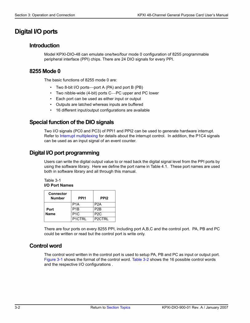
Introduction Model KPXI-DIO-48 can emulate one/two/four mode 0 configuration of 8255 programmable peripheral interface (PPI) chips. There are 24 DIO signals for every PPI.
8255 Mode 0The basic functions of 8255 mode 0 are:
• Two 8-bit I/O ports−−port A (PA) and port B (PB)• Two nibble-wide (4-bit) ports C−−PC upper and PC lower• Each port can be used as either input or output• Outputs are latched whereas inputs are buffered• 16 different input/output configurations are available
Special function of the DIO signals Two I/O signals (PC0 and PC3) of PPI1 and PPI2 can be used to generate hardware interrupt. Refer to Interrupt multiplexing for details about the interrupt control. In addition, the P1C4 signals can be used as an input signal of an event counter.
Digital I/O port programming Users can write the digital output value to or read back the digital signal level from the PPI ports by using the software library. Here we define the port name in Table 4.1. These port names are used both in software library and all through this manual.
There are four ports on every 8255 PPI, including port A,B,C and the control port. PA, PB and PC could be written or read but the control port is write only.
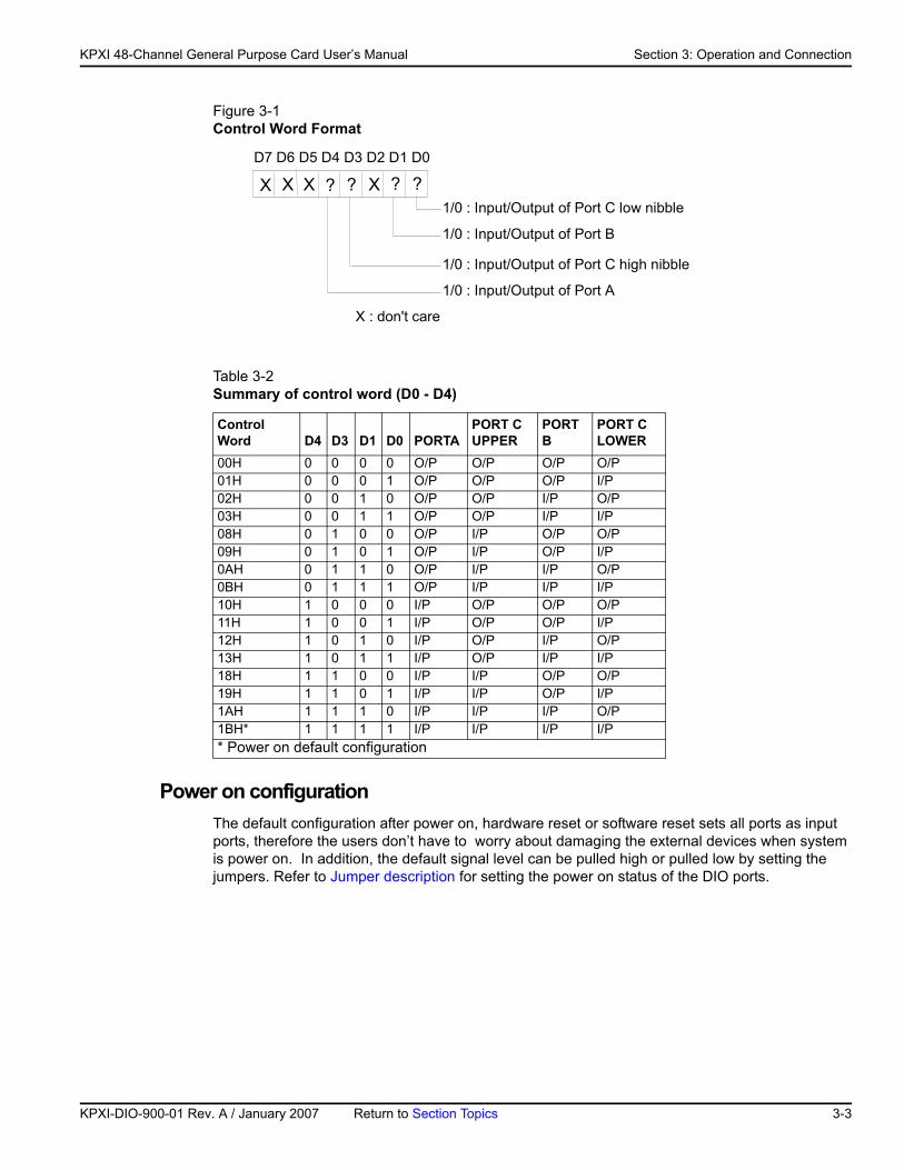
Control wordThe control word written in the control port is used to setup PA, PB and PC as input or output port. Figure 3-1 shows the format of the control word. Table 3-2 shows the 16 possible control words and the respective I/O configurations .
Table 3-1I/O Port Names
ConnectorNumber PPI1 PPI2
PortName
P1A P2AP1B P2BP1C P2CP1CTRL P2CTRL
3-2 Return to Section Topics KPXI-DIO-900-01 Rev. A / January 2007
KP
KPXI 48-Channel General Purpose Card User’s Manual Section 3: Operation and Connection
Figure 3-1Control Word Format
Power on configuration The default configuration after power on, hardware reset or software reset sets all ports as input ports, therefore the users don’t have to worry about damaging the external devices when system is power on. In addition, the default signal level can be pulled high or pulled low by setting the jumpers. Refer to Jumper description for setting the power on status of the DIO ports.
Table 3-2Summary of control word (D0 - D4)
ControlWord D4 D3 D1 D0 PORTA
PORT C UPPER
PORT B
PORT C LOWER
00H 0 0 0 0 O/P O/P O/P O/P01H 0 0 0 1 O/P O/P O/P I/P02H 0 0 1 0 O/P O/P I/P O/P03H 0 0 1 1 O/P O/P I/P I/P08H 0 1 0 0 O/P I/P O/P O/P09H 0 1 0 1 O/P I/P O/P I/P0AH 0 1 1 0 O/P I/P I/P O/P0BH 0 1 1 1 O/P I/P I/P I/P10H 1 0 0 0 I/P O/P O/P O/P11H 1 0 0 1 I/P O/P O/P I/P12H 1 0 1 0 I/P O/P I/P O/P13H 1 0 1 1 I/P O/P I/P I/P18H 1 1 0 0 I/P I/P O/P O/P19H 1 1 0 1 I/P I/P O/P I/P1AH 1 1 1 0 I/P I/P I/P O/P1BH* 1 1 1 1 I/P I/P I/P I/P* Power on default configuration
X X X ? ? ?X ?1/0 : Input/Output of Port C low nibble
D7 D6 D5 D4 D3 D2 D1 D0
1/0 : Input/Output of Port B
1/0 : Input/Output of Port C high nibble
1/0 : Input/Output of Port A
X : don't care
XI-DIO-900-01 Rev. A / January 2007 Return to Section Topics 3-3
Section 3: Operation and Connection KPXI 48-Channel General Purpose Card User’s Manual
Output data concern
CAUTION Be careful of the initial condition of digital output signals. If users set the con-trol word as output port after power on, the previous uncertain output value will be put on the output pins immediately. Therefore, BE SURE TO WRITE A SAFE VALUE TO THE PORTS BEFORE CONFIGURING THEM AS OUTPUT PORTS.
Timer/counter operation
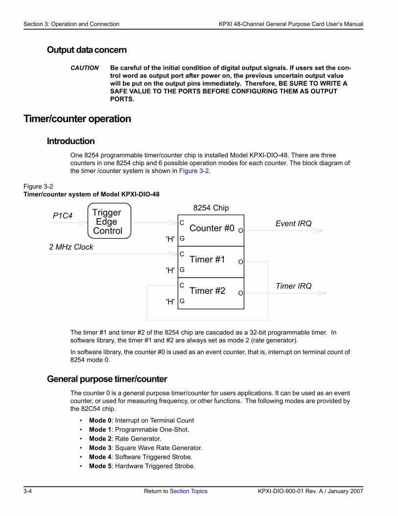
Introduction One 8254 programmable timer/counter chip is installed Model KPXI-DIO-48. There are three counters in one 8254 chip and 6 possible operation modes for each counter. The block diagram of the timer /counter system is shown in Figure 3-2.
Figure 3-2Timer/counter system of Model KPXI-DIO-48
The timer #1 and timer #2 of the 8254 chip are cascaded as a 32-bit programmable timer. In software library, the timer #1 and #2 are always set as mode 2 (rate generator).
In software library, the counter #0 is used as an event counter, that is, interrupt on terminal count of 8254 mode 0.
General purpose timer/counterThe counter 0 is a general purpose timer/counter for users applications. It can be used as an event counter, or used for measuring frequency, or other functions. The following modes are provided by the 82C54 chip.
• Mode 0: Interrupt on Terminal Count• Mode 1: Programmable One-Shot.• Mode 2: Rate Generator.• Mode 3: Square Wave Rate Generator.• Mode 4: Software Triggered Strobe.• Mode 5: Hardware Triggered Strobe.
Event IRQCounter #0
2 MHz Clock Timer #1
Timer IRQTimer #2
8254 Chip
C
G
C
G
C
G O
O
O
'H'
'H'
'H'
Trigger Edge
Control
P1C4
3-4 Return to Section Topics KPXI-DIO-900-01 Rev. A / January 2007
KP
KPXI 48-Channel General Purpose Card User’s Manual Section 3: Operation and Connection
The 8254 timer/ counter IC occupies 4 I/O address.
Cascaded 32 Bits Timer The input clock frequency of the cascaded timers is 2MHz. The output of the timer is send to the interrupt circuit (refer to Interrupt multiplexing). Therefore, the maximum and minimum watchdog timer interrupt frequency is (2MHz)/(2*2)=500KHz and (2MHz)/(65535*65535)= 0.000466Hz respectively.
Event counter and edge controlThe counter #0 of the 8254 chip can be used as an event counter. The input of counter #0 is PC4 of PPI1 (P1C4). The counter clock trigger direction (H to L or L to H) is programmable. The gate control is always enabled. The output is sent to the interrupt system which is named as event IRQ. If counter #0 is set as 8254 mode 0, the event counter IRQ will trigger when the counter value is counting down to zero.
Interrupt multiplexing
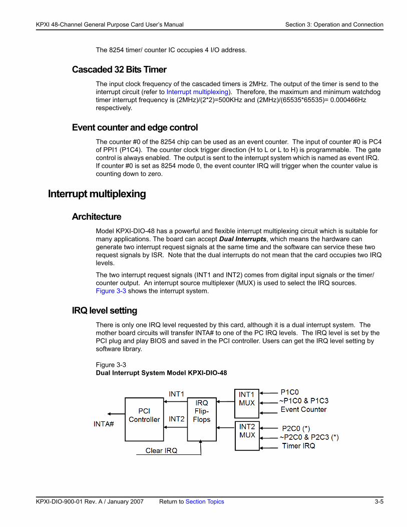
ArchitectureModel KPXI-DIO-48 has a powerful and flexible interrupt multiplexing circuit which is suitable for many applications. The board can accept Dual Interrupts, which means the hardware can generate two interrupt request signals at the same time and the software can service these two request signals by ISR. Note that the dual interrupts do not mean that the card occupies two IRQ levels.
The two interrupt request signals (INT1 and INT2) comes from digital input signals or the timer/counter output. An interrupt source multiplexer (MUX) is used to select the IRQ sources. Figure 3-3 shows the interrupt system.
IRQ level settingThere is only one IRQ level requested by this card, although it is a dual interrupt system. The mother board circuits will transfer INTA# to one of the PC IRQ levels. The IRQ level is set by the PCI plug and play BIOS and saved in the PCI controller. Users can get the IRQ level setting by software library.
Figure 3-3Dual Interrupt System Model KPXI-DIO-48
XI-DIO-900-01 Rev. A / January 2007 Return to Section Topics 3-5
Section 3: Operation and Connection KPXI 48-Channel General Purpose Card User’s Manual
Dual interrupts concernsThe PCI controller of Model KPXI-DIO-48 can receive two hardware IRQ sources. However, a PCI controller can generate only one IRQ to PCI bus, the two IRQ sources must be distinguished by ISR of the application software if the two IRQs are both used.
The application software can use a function to distinguish which interrupt is inserted. After an ISR is completed, users must check if another IRQ is also asserted, then clear the current IRQ to allow the next IRQ coming in.
The two IRQs are named as INT1 and INT2. In Model KPXI-DIO-48, INT1 comes from P1C0, P1C3 or the event counter interrupt. INT2 comes from P2C0, P2C3 or the timer interrupt. The sources of INT1 and INT2 is selectable by the Interrupt Source Control (ISC) Register.
Interrupt source controlIn the ISC register (offset 0x20), there are four bits to control the IRQ sources of INT1 and INT2.
If the application needs only one IRQ, you can disable one of the IRQ sources by software. If your application does not need any IRQ source, you can disable both interrupts. However, the PCI BIOS will still assign an IRQ level to the PCI card and occupy the PC resource if you only disable the IRQ sources without changing the initial condition of the PCI controller.
It is not recommended to change the initial condition of the PCI card by users‘ own application software.
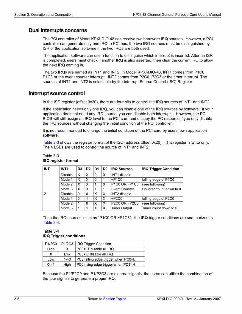
Table 3-3 shows the register format of the ISC (address offset 0x20). This register is write only. The 4 LSBs are used to control the source of INT1 and INT2.
Then the IRQ sources is set as “P1C0 OR ~P1C3”, the IRQ trigger conditions are summarized in Table 3-4.
Because the P1/P2C0 and P1/P2C3 are external signals, the users can utilize the combination of the four signals to generate a proper IRQ.
Table 3-3 ISC register format
INT INT1 D3 D2 D1 D0 IRQ Sources IRQ Trigger Condition1 Disable X X 0 0 INT1 disable --
Mode 1 X X 0 1 ~P1C0 falling edge of P1C0Mode 2 X X 1 0 P1C0 OR ~P1C3 (see following)Mode 3 X X 1 1 Event Counter Counter count down to 0
2 Disable 0 0 X X INT2 disable --Mode 1 0 1 X X ~P2C0 falling edge of P2C0Mode 2 1 0 X X P2C0 OR ~P2C3 (see following) Mode 3 1 1 X X Timer Output Timer count down to 0
Table 3-4IRQ Trigger conditions
P1/2C0 P1/2C3 IRQ Trigger ConditionHigh X PC0=‘H’ disable all IRQ
X Low PC3=‘L’ disable all IRQLow 1->0 PC3 falling edge trigger when PC0=L0->1 High PC0 rising edge trigger when PC3=H
3-6 Return to Section Topics KPXI-DIO-900-01 Rev. A / January 2007
KP
KPXI 48-Channel General Purpose Card User’s Manual Section 3: Operation and Connection
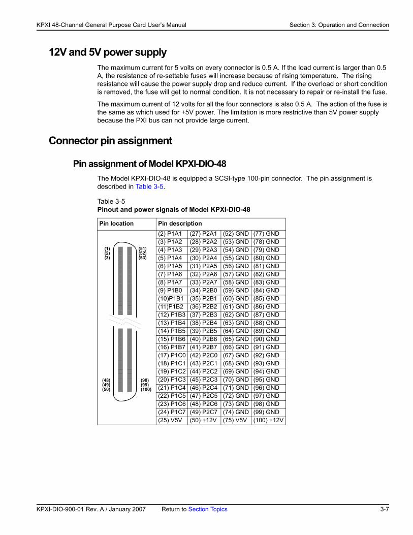
12V and 5V power supply The maximum current for 5 volts on every connector is 0.5 A. If the load current is larger than 0.5 A, the resistance of re-settable fuses will increase because of rising temperature. The rising resistance will cause the power supply drop and reduce current. If the overload or short condition is removed, the fuse will get to normal condition. It is not necessary to repair or re-install the fuse.
The maximum current of 12 volts for all the four connectors is also 0.5 A. The action of the fuse is the same as which used for +5V power. The limitation is more restrictive than 5V power supply because the PXI bus can not provide large current.
Connector pin assignment
Pin assignment of Model KPXI-DIO-48The Model KPXI-DIO-48 is equipped a SCSI-type 100-pin connector. The pin assignment is described in Table 3-5.
Table 3-5Pinout and power signals of Model KPXI-DIO-48
Pin location Pin description(2) P1A1 (27) P2A1 (52) GND (77) GND(3) P1A2 (28) P2A2 (53) GND (78) GND(4) P1A3 (29) P2A3 (54) GND (79) GND(5) P1A4 (30) P2A4 (55) GND (80) GND(6) P1A5 (31) P2A5 (56) GND (81) GND(7) P1A6 (32) P2A6 (57) GND (82) GND(8) P1A7 (33) P2A7 (58) GND (83) GND(9) P1B0 (34) P2B0 (59) GND (84) GND(10)P1B1 (35) P2B1 (60) GND (85) GND(11)P1B2 (36) P2B2 (61) GND (86) GND(12) P1B3 (37) P2B3 (62) GND (87) GND(13) P1B4 (38) P2B4 (63) GND (88) GND(14) P1B5 (39) P2B5 (64) GND (89) GND(15) P1B6 (40) P2B6 (65) GND (90) GND(16) P1B7 (41) P2B7 (66) GND (91) GND(17) P1C0 (42) P2C0 (67) GND (92) GND(18) P1C1 (43) P2C1 (68) GND (93) GND(19) P1C2 (44) P2C2 (69) GND (94) GND(20) P1C3 (45) P2C3 (70) GND (95) GND(21) P1C4 (46) P2C4 (71) GND (96) GND(22) P1C5 (47) P2C5 (72) GND (97) GND(23) P1C6 (48) P2C6 (73) GND (98) GND(24) P1C7 (49) P2C7 (74) GND (99) GND(25) V5V (50) +12V (75) V5V (100) +12V
(1)(2)(3)
(52)(53)
(51)
(48)(49)(50)
(98)(99)(100)
XI-DIO-900-01 Rev. A / January 2007 Return to Section Topics 3-7
Section 3: Operation and Connection KPXI 48-Channel General Purpose Card User’s Manual
The DIO pin names described in Table 3-5 are specified as PnXb,
where:
P: DIO pin
n: PPI reference number n=1 or 2.
X: port name, X= ‘A’ , ‘B’ or ‘C’
b: bit number of a port, b=0~7
For example, P1C4 means bit 4 of port C on connector PPI1.
NOTE The power supply pins are protected by re-settable fuses. Refer to 12V and 5V power supply for details of the power supply.
3-8 Return to Section Topics KPXI-DIO-900-01 Rev. A / January 2007
Section 4 Registers
In this section:
Topic Page
Introduction......................................................................................... 4-2PCI PnP registers ............................................................................. 4-2I/O address map ............................................................................... 4-2
Section 4: Registers KPXI 48-Channel General Purpose Card User’s Manual
IntroductionThis section describes the details of the registers and its structure. This information is important for programmers who want to control the hardware with low-level programming
However, we suggest users become familiar with the PCI interface before starting low-level programming. In addition, the contents of this section can help users understand how to use software driver to manipulate this card.
NOTE Direct register access can be difficult to program. All users are encouraged to use the KDIO-DRVR driver interface instead of direct access to the registers. This section is included only as a reference for customers who absolutely require the efficiency of register access.
PCI PnP registers This PCI card functions as a 32-bit PCI target device to any master on the PCI bus. There are three types of registers: PCI Configuration Registers (PCR), Local Configuration Registers (LCR) and registers.
The PCR, which is PCI-bus specifications compliant, is initialized and controlled by the plug & play (PnP) PCI BIOS. Users may obtain more information on the PCI BIOS specification to better understand the operation of the PCR. Please contact PCISIG to acquire the specifications of the PCI interface.
The PCI bus controller PCI-9050 is provided by PLX technology Inc. (www.plxtech.com). For more information about the LCR, please visit PLX technology’s web site to download relative information. It is not necessary for users to fully understand the details of the LCR if the software library provided is used. The PCI PnP BIOS assigns the base address of the LCR. The assigned address is located at an offset of 14h from the PCR.
Please do not try to modify the base address and interrupt which assigned by the PCI PnP BIOS, it may cause resource confliction in your system.
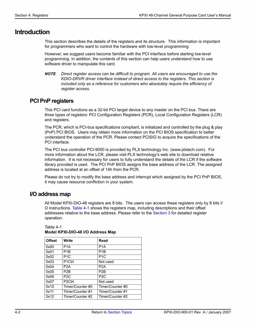
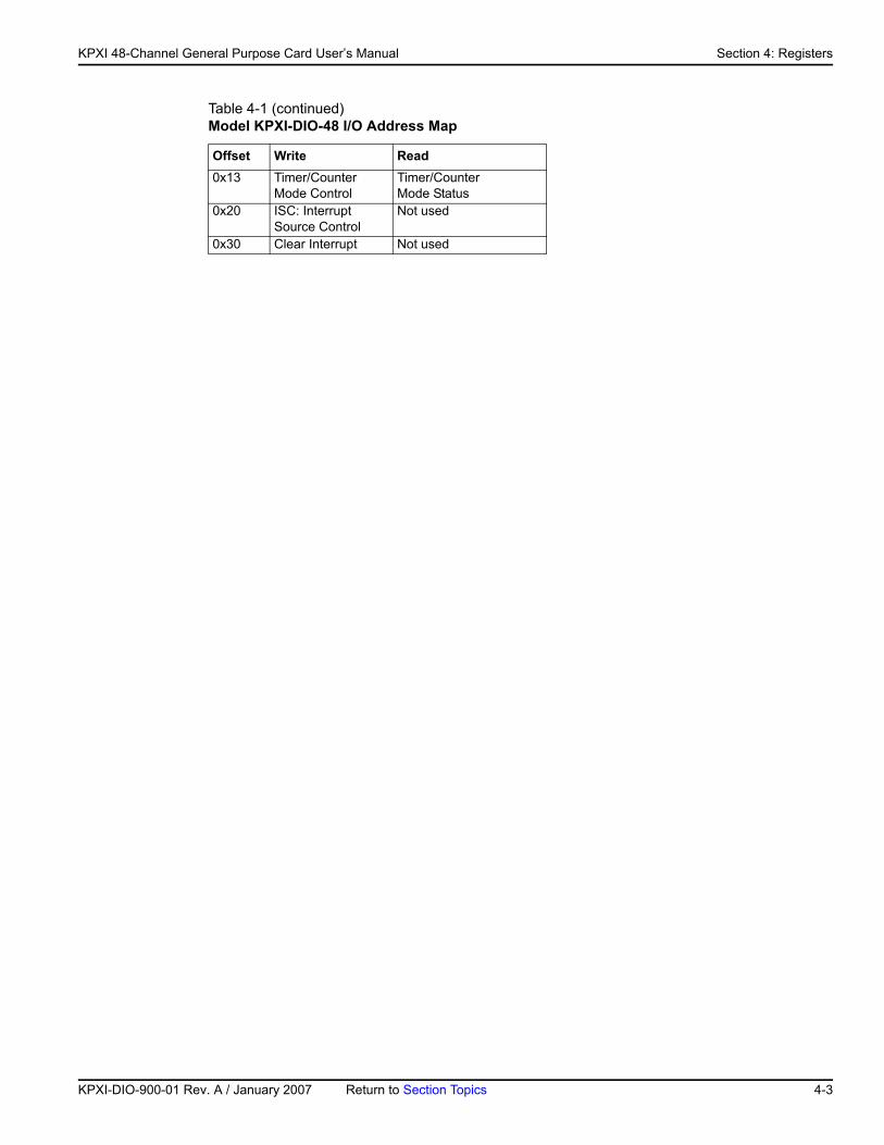
I/O address mapAll Model KPXI-DIO-48 registers are 8 bits. The users can access these registers only by 8 bits I/O instructions. Table 4-1 shows the registers map, including descriptions and their offset addresses relative to the base address. Please refer to the Section 3 for detailed register operation.
Table 4-1 Model KPXI-DIO-48 I/O Address Map
Offset Write Read0x00 P1A P1A0x01 P1B P1B0x02 P1C P1C0x03 P1Ctrl Not used 0x04 P2A P2A0x05 P2B P2B0x06 P2C P2C0x07 P2Ctrl Not used 0x10 Timer/Counter #0 Timer/Counter #00x11 Timer/Counter #1 Timer/Counter #10x12 Timer/Counter #2 Timer/Counter #2
4-2 Return to Section Topics KPXI-DIO-900-01 Rev. A / January 2007
KP
KPXI 48-Channel General Purpose Card User’s Manual Section 4: Registers
0x13 Timer/CounterMode Control
Timer/CounterMode Status
0x20 ISC: Interrupt Source Control
Not used
0x30 Clear Interrupt Not used
Table 4-1 (continued)Model KPXI-DIO-48 I/O Address Map
Offset Write Read
XI-DIO-900-01 Rev. A / January 2007 Return to Section Topics 4-3
Section 4: Registers KPXI 48-Channel General Purpose Card User’s Manual
This page left blank intentionally.
4-4 Return to Section Topics KPXI-DIO-900-01 Rev. A / January 2007
Appendix A KDIO-DRVR User’s Guide
In this appendix:
Topic Page
Introduction to KDIO-DRVR ............................................................ A-2About the KDIO-DRVR software....................................................... A-2KDIO-DRVR hardware support......................................................... A-2KDIO-DRVR language support......................................................... A-2
KDIO-DRVR overview ....................................................................... A-3General configuration function group ............................................... A-3Actual sampling rate function group ................................................. A-4Analog output function group............................................................ A-4Digital input function group ............................................................... A-4Digital output function group............................................................. A-6Timer/counter function group............................................................ A-7DIO function group ........................................................................... A-8
Creating a KDIO-DRVR application............................................... A-9Contiguous memory allocation in driver for continuous operation.... A-9
Fundamentals of building Windows XP/2000 Application...... A-9Microsoft® Visual Basic (Version 6.0) ............................................... A-9Using Microsoft Visual Basic.NET .................................................. A-11Microsoft Visual C/C++ ................................................................... A-11
KDIO-DRVR application hints....................................................... A-11Digital input programming hints ...................................................... A-12Digital output programming hints .................................................... A-17DAQ event message programming hints........................................ A-21Interrupt event message programming hints .................................. A-22
Continuous data transfer in KDIO-DRVR .................................. A-23Continuous data transfer mechanism............................................. A-23Double-buffered / multiple-buffered DI operation............................ A-23
KDIO-DRVR utilities for Win32 ..................................................... A-25KDIO-DRVR configuration utility (configdrv)................................... A-25KDIO-DRVR data file converter utility (KIDAQCvt)......................... A-26
Appendix A: KDIO-DRVR User’s Guide KPXI 48-Channel General Purpose Card User’s Manual
Introduction to KDIO-DRVR
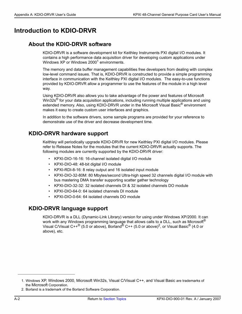
About the KDIO-DRVR softwareKDIO-DRVR is a software development kit for Keithley Instruments PXI digital I/O modules. It contains a high performance data acquisition driver for developing custom applications under Windows XP or Windows 20001 environments.
The memory and data buffer management capabilities free developers from dealing with complex low-level command issues. That is, KDIO-DRVR is constructed to provide a simple programming interface in communication with the Keithley PXI digital I/O modules. The easy-to-use functions provided by KDIO-DRVR allow a programmer to use the features of the module in a high level way.
Using KDIO-DRVR also allows you to take advantage of the power and features of Microsoft Win32s® for your data acquisition applications, including running multiple applications and using extended memory. Also, using KDIO-DRVR under in the Microsoft Visual Basic® environment makes it easy to create custom user interfaces and graphics.
In addition to the software drivers, some sample programs are provided for your reference to demonstrate use of the driver and decrease development time.
KDIO-DRVR hardware supportKeithley will periodically upgrade KDIO-DRVR for new Keithley PXI digital I/O modules. Please refer to Release Notes for the modules that the current KDIO-DRVR actually supports. The following modules are currently supported by the KDIO-DRVR driver:
• KPXI-DIO-16-16: 16-channel isolated digital I/O module• KPXI-DIO-48: 48-bit digital I/O module• KPXI-RDI-8-16: 8 relay output and 16 isolated input module• KPXI-DIO-32-80M: 80 Mbytes/second Ultra-high speed 32 channels digital I/O module with
bus mastering DMA transfer supporting scatter gather technology • KPXI-DIO-32-32: 32 isolated channels DI & 32 isolated channels DO module • KPXI-DIO-64-0: 64 isolated channels DI module• KPXI-DIO-0-64: 64 isolated channels DO module
KDIO-DRVR language supportKDIO-DRVR is a DLL (Dynamic-Link Library) version for using under Windows XP/2000. It can work with any Windows programming language that allows calls to a DLL, such as Microsoft® Visual C/Visual C++® (5.0 or above), Borland® C++ (5.0 or above)2, or Visual Basic® (4.0 or above), etc.
1. Windows XP, Windows 2000, Microsoft Win32s, Visual C/Visual C++, and Visual Basic are trademarks of the Microsoft Corporation.
2. Borland is a trademark of the Borland Software Corporation.
A-2 Return to Section Topics KPXI-DIO-900-01 Rev. A / January 2007
KP
KPXI 48-Channel General Purpose Card User’s Manual Appendix A: KDIO-DRVR User’s Guide
KDIO-DRVR overviewNOTE Based on the configuration of an individual module, some of the function groups will not
apply to a particular module.
This section describes the classes of functions in KDIO-DRVR and briefly describes each function.
KDIO-DRVR functions are grouped to the following classes:
• General Configuration Function Group• Actual Sampling Rate Function Group• Analog Output Function Group• Digital Input Function Group
– Digital Input Configuration functions – One-Shot Digital Input functions – Continuous Digital Input functions – Asynchronous Digital Input Monitoring functions
• Digital Output Function Group – Digital Output Configuration functions – One-Shot Digital Output functions – Continuous Digital Output functions – Asynchronous Digital Output Monitoring functions
• Timer/Counter Function Group• DIO Function Group
– Digital Input/Output Configuration function – Dual-Interrupt System Setting function
General configuration function groupUse these functions to initialize and configure the data acquisition card.
KDIO_Register_Card
Initializes the hardware and software states of a KIDAQ PCI-bus data acquisition card. Register_Card must be called before any other KDIO-DRVR library functions can be called for that card.
KDIO_Release_Card
Tells KDIO-DRVR library that this registered card is not used currently and can be released. This would make room for a new card to be registered.
KDIO_GetCardType
Gets the card type of the device with a specified card index.
KDIO_GetCardIndexFromID
Gets the card type and the sequence number of the device with a specified card id.
KDIO_GetBaseAddr
Gets the I/O base addresses of the device with a specified card index.
XI-DIO-900-01 Rev. A / January 2007 Return to Section Topics A-3
Appendix A: KDIO-DRVR User’s Guide KPXI 48-Channel General Purpose Card User’s Manual
KDIO_GetLCRAddr
Gets the LCR base address (defined by the PCI controller on board) of the device with a specified card index.
Actual sampling rate function group
KDIO_GetActualRate
Returns the actual sampling rate the device will perform for the defined sampling rate value.
Analog output function group
One-shot analog output functions
KDIO_AO_WriteChannel
Writes a binary value to the specified analog output channel.
KDIO_AO_VWriteChannel
Accepts a voltage value, scales it to the proper binary value and writes a binary value to the specified analog output channel.
KDIO_AO_VoltScale
Scales a voltage to a binary value.
Digital input function group
Digital input configuration functions
KDIO_DI_DIO32M80_Config
Informs KDIO-DRVR library of the trigger source and trigger properties selected for the digital input operation of the KPXI-DIO-32-80M. You must call this function before calling the function to perform continuous digital input operation of the KPXI-DIO-32-80M. This function is used only with Model KPXI-DIO-32-80M.
KDIO_DI_InitialMemoryAllocated
Gets the actual size of digital input DMA memory that is available in the device driver.
One-Shot Digital Input Functions
KDIO_DI_ReadLine
Reads the digital logic state of the specified digital line in the specified port.
KDIO_DI_ReadPort
Reads digital data from the specified digital input port.
A-4 Return to Section Topics KPXI-DIO-900-01 Rev. A / January 2007
KP
KPXI 48-Channel General Purpose Card User’s Manual Appendix A: KDIO-DRVR User’s Guide
Continuous digital input functions
KDIO_DI_ContReadPort
Performs continuous digital input on the specified digital input port at a rate as close as possible to the rate you specified.
KDIO_DI_ContReadPortToFile
Performs continuous digital input on the specified digital input port at a rate as close as possible to the rate you specified and saves the acquired data in a disk file.
KDIO_DI_ContStatus
Checks the current status of the continuous digital input operation.
KDIO_DI_EventCallBack
Controls and notifies the user’s application when a specified DAQ event occurs. The notification is performed through a user-specified callback function.
KDIO_DI_ContMultiBufferSetup
Set up the buffer for multi-buffered continuous digital input.
KDIO_DI_ContMultiBufferStart
Starts the multi-buffered continuous digital input on the specified digital input port at a rate as close as possible to the rate you specified.
Asynchronous digital input monitoring functions
KDIO_DI_AsyncCheck
Checks the current status of the asynchronous digital input operation.
KDIO_DI_AsyncClear
Stops the asynchronous digital input operation.
KDIO_DI_AsyncDblBufferTransfer
Copies half of the data of circular buffer to user buffer. You can execute this function repeatedly to return sequential half buffers of the data.
KDIO_DI_AsyncMultiBufferNextReady
Checks whether the next buffer of data in circular buffer is ready for transfer during an asynchronous multi-buffered digital input operation.
KDIO_DI_AsyncDblBufferOverrun
Checks or clears overrun status of the double-buffered digital input operation.
XI-DIO-900-01 Rev. A / January 2007 Return to Section Topics A-5
Appendix A: KDIO-DRVR User’s Guide KPXI 48-Channel General Purpose Card User’s Manual
Digital output function group
Digital output configuration functions
KDIO_DO_DIO32M80_Config
Informs KDIO-DRVR library of the trigger source and trigger properties selected for the digital output operation of the KPXI-DIO-32-80M. You must call this function before calling the function to perform continuous digital output operation of the KPXI-DIO-32-80M. This function is used only with Model KPXI-DIO-32-80M.
KDIO_DO_InitialMemoryAllocated
Gets the actual size of digital output DMA memory that is available in the device driver.
One-Shot Digital Output Functions
KDIO_DO_WriteLine
Sets the specified digital output line in the specified digital output port to the specified state. This function is only available for those cards that support digital output read-back functionality.
KDIO_DO_WritePort
Writes digital data to the specified digital output port.
KDIO_DO_ReadLine
Reads the specified digital output line in the specified digital output port.
KDIO_DO_ReadPort
Reads digital data from the specified digital output port.
Continuous digital output functions
KDIO_DO_ContWritePort
Performs continuous digital output on the specified digital output port at a rate as close as possible to the rate you specified.
KDIO_DO_ContStatus
Checks the current status of the continuous digital output operation.
KDIO_DO_EventCallBack
Controls and notifies the user’s application when a specified DAQ event occurs. The notification is performed through a user-specified callback function.
KDIO_DO_PGStart
Performs pattern generation operation.
KDIO_DO_PGStop
Stops pattern generation operation.
A-6 Return to Section Topics KPXI-DIO-900-01 Rev. A / January 2007
KP
KPXI 48-Channel General Purpose Card User’s Manual Appendix A: KDIO-DRVR User’s Guide
KDIO_DO_ContMultiBufferSetup
Set up the buffer for multi-buffered continuous digital output.
KDIO_DO_ContMultiBufferStart
Starts the multi-buffered continuous digital output on the specified digital output port at a rate as close as possible to the rate you specified.
Asynchronous digital output monitoring functions
KDIO_DO_AsyncCheck
Checks the current status of the asynchronous digital output operation.
KDIO_DO_AsyncClear
Stops the asynchronous digital output operation.
KDIO_DO_AsyncMultiBufferNextReady
Checks whether the next buffer is ready for new data during an asynchronous multi-buffered digital output operation.
Timer/counter function group
Timer/counter functions
KDIO_CTR_Setup
Configures the selected counter to operate in the specified mode.
KDIO_CTR_Read
Reads the current contents of the selected counter.
KDIO_CTR_Clear
Sets the output of the selected counter to the specified state.
KDIO_CTR_Update
Writes a new initial count to the selected counter.
KDIO_CTR_CT12_ClkSrc_Config
Sets the counter clock source.
KDIO_CTR_CT12_CK1_Config
Sets the source of CK1.
KDIO_CTR_CT12_Debounce_Config
Sets the debounce clock.
XI-DIO-900-01 Rev. A / January 2007 Return to Section Topics A-7
Appendix A: KDIO-DRVR User’s Guide KPXI 48-Channel General Purpose Card User’s Manual
DIO function group
Digital input/output configuration functions
KDIO_DIO_PortConfig
This function is only used by the Digital I/O cards whose I/O port can be set as input port or output port. This function informs KDIO-DRVR library of the port direction selected for the digital input/output operation. You must call this function before calling functions to perform digital input/output operation.
Dual-interrupt system setting functions
KDIO_SetDualInterrupt
Controls two interrupt sources of Dual Interrupt system.
KDIO_INT_EventMessage
Controls and notifies the user’s application when an interrupt event occurs. The notification is performed through a user-specified callback function or the Windows PostMessage API.
KDIO_INT1_EventMessage
Controls the interrupt sources of INT1 of Dual Interrupt system and notifies the user’s application when an interrupt event occurs. The notification is performed through a user-specified callback function or the Windows PostMessage API.
KDIO_INT2_EventMessage
Controls the interrupt sources of INT2 of Dual Interrupt system and notifies the user’s application when an interrupt event occurs. The notification is performed through a user-specified callback function or the Windows PostMessage API.
Local interrupt setting functions
KDIO_DIO32M80_SetInterrupt
Controls the interrupt sources (AUXDI and Timer2) of local Interrupt system of KPXI-DIO-32-80M. This function is used only with Model KPXI-DIO-32-80M.
KDIO_AUXDI_EventMessage
Controls AUXDI Interrupt and notifies the user’s application when an interrupt event occurs. The notification is performed through a user-specified callback function or the Windows PostMessage API.
KDIO_T2_EventMessage
Controls Timer2 Interrupt and notifies the user’s application when an interrupt event occurs. The notification is performed through a user-specified callback function or the Windows PostMessage API.
A-8 Return to Section Topics KPXI-DIO-900-01 Rev. A / January 2007
KP
KPXI 48-Channel General Purpose Card User’s Manual Appendix A: KDIO-DRVR User’s Guide
Creating a KDIO-DRVR application
Contiguous memory allocation in driver for continuous operationThe continuous data transfer functions in KDIO-DRVR input or output blocks of data to or from a Keithley Instruments PXI digital I/O device. To avoid the data transfer performance reduction caused by memory fragmentation, KDIO-DRVR allocates physically contiguous buffers in device driver when the system boots.
KDIO-DRVR provides a utility, configdrv to set/modify the sizes of contiguous memory allocated in driver for continuous analog input, analog output, digital input, digital output. Device driver will try to allocate these sizes of memory. The size of initially allocated memory is the maximum memory size that continuous data transfer can be performed. Please refer to the section, KDIO-DRVR configuration utility (configdrv), for the description of this utility.
KDIO-DRVR inputs or outputs blocks of data stored in the driver buffer to or from a Keithley PXI device. For input operations, the specified count of data are transferred to the driver buffer and KDIO-DRVR copies the data from the driver buffer (kernel level) to a user buffer (user level). For output operations, KDIO-DRVR copies the data from a user buffer (driver level) to the driver buffer (kernel level) and transfers outgoing data from the driver buffer to the Keithley PXI device.
However, if only polling I/O is performed, the initially allocated memory is not needed and you can use the utility, KDIO-DRVR configuration utility (configdrv) to set the buffer size to be 0.
Fundamentals of building Windows XP/2000 Application The following paragraphs outline how to create Windows1 XP/2000 KDAQ-DRVR projects using Microsoft Visual Basic® (Version 6.0), Microsoft Visual Basic.NET, and Microsoft Visual C/C++®.
Microsoft® Visual Basic (Version 6.0)To create a Windows XP/2000® Keithley KDIO-DRVR application using the API and Microsoft Visual Basic, follow these steps:
Step 1: Enter Visual Basic and open or create a project to use KDIO-DRVRTo create a new project, select New Project from the File menu.
To use an existing project:
1. Open the file by selecting Open Project from the File menu. The Open Project dialog box appears (Figure A-1).
1. Windows XP, Windows 2000, Microsoft Visual Basic.NET, Microsoft Visual C/Visual C++, and Microsoft Visual Basic are trademarks of the Microsoft Corporation.
XI-DIO-900-01 Rev. A / January 2007 Return to Section Topics A-9
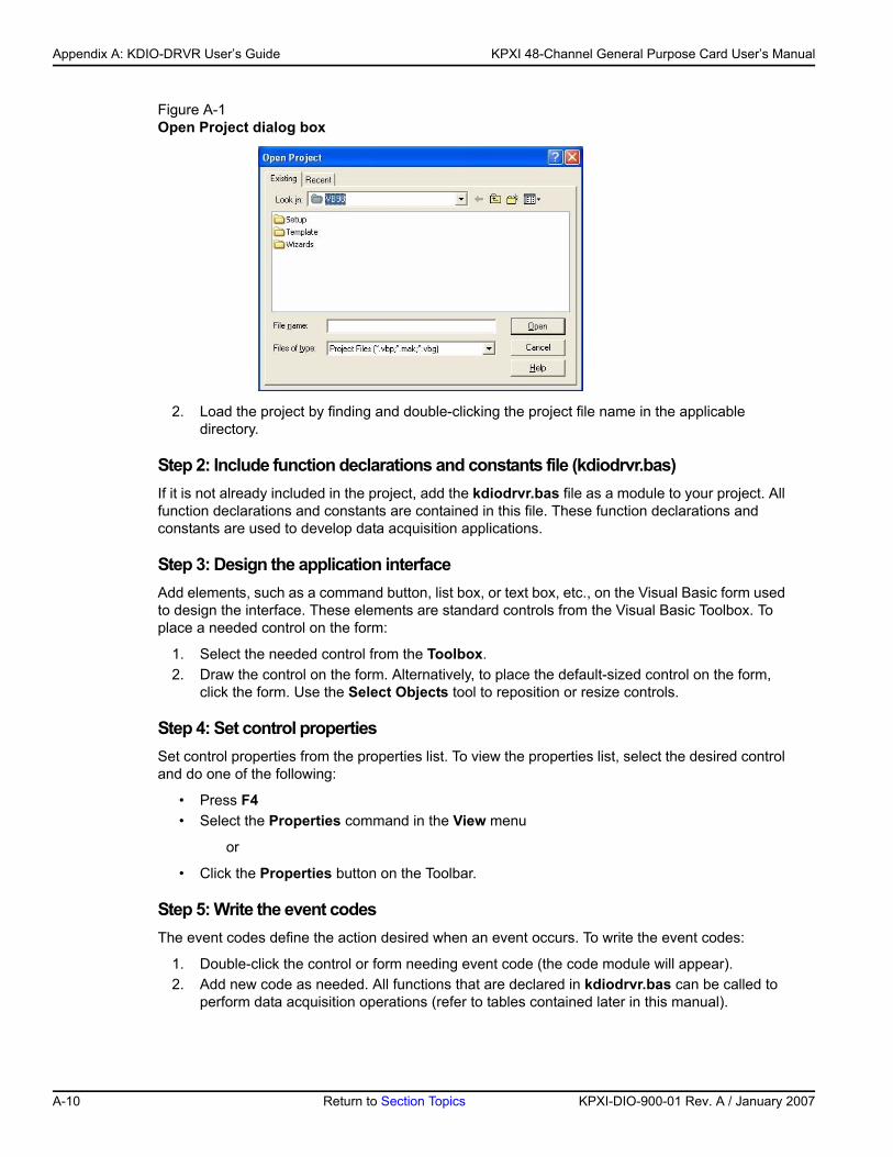
Appendix A: KDIO-DRVR User’s Guide KPXI 48-Channel General Purpose Card User’s Manual
Figure A-1Open Project dialog box
2. Load the project by finding and double-clicking the project file name in the applicable directory.
Step 2: Include function declarations and constants file (kdiodrvr.bas)If it is not already included in the project, add the kdiodrvr.bas file as a module to your project. All function declarations and constants are contained in this file. These function declarations and constants are used to develop data acquisition applications.
Step 3: Design the application interfaceAdd elements, such as a command button, list box, or text box, etc., on the Visual Basic form used to design the interface. These elements are standard controls from the Visual Basic Toolbox. To place a needed control on the form:
1. Select the needed control from the Toolbox. 2. Draw the control on the form. Alternatively, to place the default-sized control on the form,
click the form. Use the Select Objects tool to reposition or resize controls.
Step 4: Set control propertiesSet control properties from the properties list. To view the properties list, select the desired control and do one of the following:
• Press F4• Select the Properties command in the View menu
or
• Click the Properties button on the Toolbar.
Step 5: Write the event codesThe event codes define the action desired when an event occurs. To write the event codes:
1. Double-click the control or form needing event code (the code module will appear). 2. Add new code as needed. All functions that are declared in kdiodrvr.bas can be called to
perform data acquisition operations (refer to tables contained later in this manual).
A-10 Return to Section Topics KPXI-DIO-900-01 Rev. A / January 2007
KP
KPXI 48-Channel General Purpose Card User’s Manual Appendix A: KDIO-DRVR User’s Guide
Step 6: Run your applicationTo run the application, either:
• Press F5• Select Start from the Run menu
or
• Click the Start icon on the Toolbar
Using Microsoft Visual Basic.NETTo create a data acquisition application using KDAQ-DRVR and Visual Basic.NET, use the procedure for Microsoft® Visual Basic (Version 6.0) as an outline, but in step 2, use the file named KDIODRVR.VB (instead of the file named kdiodrvr.bas).
Microsoft Visual C/C++To create a Windows XP/2000 KDAQ-DRVR library application using the KDAQ-DRVR function library and Microsoft Visual C/C++, follow these steps:
Step 1: Enter Visual C/C++ and open or create a project that will use the KDIO-DRVR
NOTE The project can be a new or existing one.
Step 2: Include function declarations and constants file (kdiodrvr.h)Include kdiodrvr.h in the C/C++ source files that call KDIO-DRVR functions by adding the following statement in the source file:
#include "kdiodrvr.h"
NOTE: KDIO-DRVR function declarations and constants are contained in kdiodrvr.h. Use the functions and constants to develop data-acquisition applications.
Step 3: Build your application 1. Set suitable compile and link options. 2. Select Build from the Build menu (Visual C/C++ 4.0 and higher). 3. Remember to link the Keithley Command Compatible library: KDIO-DRVR.LIB
KDIO-DRVR application hintsThis section provides the programming schemes showing the function flow of that KDIO-DRVR performs analog I/O and digital I/O.
The figure below shows the basic building blocks of a KDIO-DRVR application. However, except using KDIO_Register_Card at the beginning and KDIO_Release_Card at the end, depending on the specific devices and applications you have, the KDIO-DRVR functions comprising each building block vary.
XI-DIO-900-01 Rev. A / January 2007 Return to Section Topics A-11
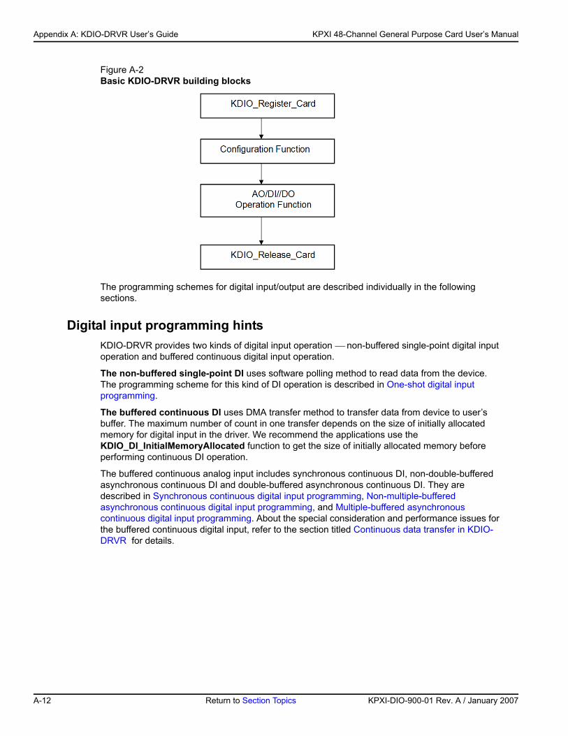
Appendix A: KDIO-DRVR User’s Guide KPXI 48-Channel General Purpose Card User’s Manual
Figure A-2Basic KDIO-DRVR building blocks
The programming schemes for digital input/output are described individually in the following sections.
Digital input programming hintsKDIO-DRVR provides two kinds of digital input operation ⎯ non-buffered single-point digital input operation and buffered continuous digital input operation.
The non-buffered single-point DI uses software polling method to read data from the device. The programming scheme for this kind of DI operation is described in One-shot digital input programming.
The buffered continuous DI uses DMA transfer method to transfer data from device to user’s buffer. The maximum number of count in one transfer depends on the size of initially allocated memory for digital input in the driver. We recommend the applications use the KDIO_DI_InitialMemoryAllocated function to get the size of initially allocated memory before performing continuous DI operation.
The buffered continuous analog input includes synchronous continuous DI, non-double-buffered asynchronous continuous DI and double-buffered asynchronous continuous DI. They are described in Synchronous continuous digital input programming, Non-multiple-buffered asynchronous continuous digital input programming, and Multiple-buffered asynchronous continuous digital input programming. About the special consideration and performance issues for the buffered continuous digital input, refer to the section titled Continuous data transfer in KDIO-DRVR for details.
A-12 Return to Section Topics KPXI-DIO-900-01 Rev. A / January 2007
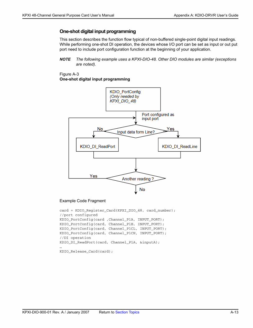
KP
KPXI 48-Channel General Purpose Card User’s Manual Appendix A: KDIO-DRVR User’s Guide
One-shot digital input programmingThis section describes the function flow typical of non-buffered single-point digital input readings. While performing one-shot DI operation, the devices whose I/O port can be set as input or out put port need to include port configuration function at the beginning of your application.
NOTE The following example uses a KPXI-DIO-48. Other DIO modules are similar (exceptions are noted).
Figure A-3One-shot digital input programming
Example Code Fragment
card = KDIO_Register_Card(KPXI_DIO_48, card_number);//port configured KDIO_PortConfig(card ,Channel_P1A, INPUT_PORT);KDIO_PortConfig(card, Channel_P1B, INPUT_PORT);KDIO_PortConfig(card, Channel_P1CL, INPUT_PORT);KDIO_PortConfig(card, Channel_P1CH, INPUT_PORT);//DI operationKDIO_DI_ReadPort(card, Channel_P1A, &inputA);…KDIO_Release_Card(card);
XI-DIO-900-01 Rev. A / January 2007 Return to Section Topics A-13
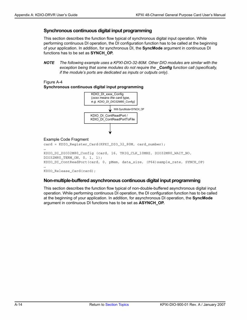
Appendix A: KDIO-DRVR User’s Guide KPXI 48-Channel General Purpose Card User’s Manual
Synchronous continuous digital input programmingThis section describes the function flow typical of synchronous digital input operation. While performing continuous DI operation, the DI configuration function has to be called at the beginning of your application. In addition, for synchronous DI, the SyncMode argument in continuous DI functions has to be set as SYNCH_OP.
NOTE The following example uses a KPXI-DIO-32-80M. Other DIO modules are similar with the exception being that some modules do not require the _Config function call (specifically, if the module’s ports are dedicated as inputs or outputs only).
Figure A-4Synchronous continuous digital input programming
Example Code Fragmentcard = KDIO_Register_Card(KPXI_DIO_32_80M, card_number);…KDIO_DI_DIO32M80_Config (card, 16, TRIG_CLK_10MHZ, DIO32M80_WAIT_NO, DIO32M80_TERM_ON, 0, 1, 1);KDIO_DI_ContReadPort(card, 0, pMem, data_size, (F64)sample_rate, SYNCH_OP)…KDIO_Release_Card(card);
Non-multiple-buffered asynchronous continuous digital input programmingThis section describes the function flow typical of non-double-buffered asynchronous digital input operation. While performing continuous DI operation, the DI configuration function has to be called at the beginning of your application. In addition, for asynchronous DI operation, the SyncMode argument in continuous DI functions has to be set as ASYNCH_OP.
KDIO_DI_xxxx_Config(xxxx means the card type,e.g. KDIO_DI_DIO32M80_Config)
KDIO_DI_ContReadPort /KDIO_DI_ContReadPortToFile
With SyncMode=SYNCH_OP
A-14 Return to Section Topics KPXI-DIO-900-01 Rev. A / January 2007
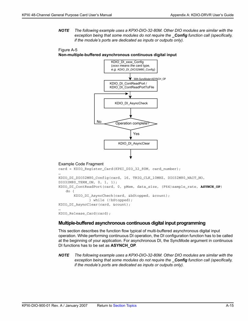
KP
KPXI 48-Channel General Purpose Card User’s Manual Appendix A: KDIO-DRVR User’s Guide
NOTE The following example uses a KPXI-DIO-32-80M. Other DIO modules are similar with the exception being that some modules do not require the _Config function call (specifically, if the module’s ports are dedicated as inputs or outputs only).
Figure A-5Non-multiple-buffered asynchronous continuous digital input
Example Code Fragmentcard = KDIO_Register_Card(KPXI_DIO_32_80M, card_number);…KDIO_DI_DIO32M80_Config(card, 16, TRIG_CLK_10MHZ, DIO32M80_WAIT_NO, DIO32M80_TERM_ON, 0, 1, 1);KDIO_DI_ContReadPort(card, 0, pMem, data_size, (F64)sample_rate, ASYNCH_OP)
do { KDIO_DI_AsyncCheck(card, &bStopped, &count); } while (!bStopped);KDIO_DI_AsyncClear(card, &count);…KDIO_Release_Card(card);
Multiple-buffered asynchronous continuous digital input programmingThis section describes the function flow typical of multi-buffered asynchronous digital input operation. While performing continuous DI operation, the DI configuration function has to be called at the beginning of your application. For asynchronous DI, the SyncMode argument in continuous DI functions has to be set as ASYNCH_OP.
NOTE The following example uses a KPXI-DIO-32-80M. Other DIO modules are similar with the exception being that some modules do not require the _Config function call (specifically, if the module’s ports are dedicated as inputs or outputs only).
KDIO_DI_xxxx_Config(xxxx means the card type,e.g. KDIO_DI_DIO32M80_Config)
KDIO_DI_ContReadPort /KDIO_DI_ContReadPortToFile
KDIO_DI_AsyncCheck
Operation complete?
Yes
No
With SyncMode=ASYNCH_OP
KDIO_DI_AsyncClear
XI-DIO-900-01 Rev. A / January 2007 Return to Section Topics A-15
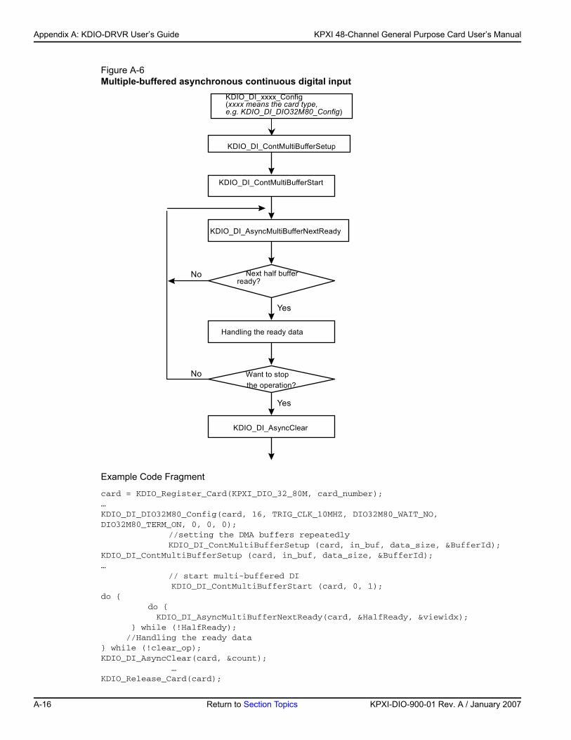
Appendix A: KDIO-DRVR User’s Guide KPXI 48-Channel General Purpose Card User’s Manual
Figure A-6Multiple-buffered asynchronous continuous digital input
Example Code Fragment
card = KDIO_Register_Card(KPXI_DIO_32_80M, card_number);…KDIO_DI_DIO32M80_Config(card, 16, TRIG_CLK_10MHZ, DIO32M80_WAIT_NO, DIO32M80_TERM_ON, 0, 0, 0);
//setting the DMA buffers repeatedlyKDIO_DI_ContMultiBufferSetup (card, in_buf, data_size, &BufferId);
KDIO_DI_ContMultiBufferSetup (card, in_buf, data_size, &BufferId);… // start multi-buffered DI KDIO_DI_ContMultiBufferStart (card, 0, 1);do {
do { KDIO_DI_AsyncMultiBufferNextReady(card, &HalfReady, &viewidx); } while (!HalfReady); //Handling the ready data} while (!clear_op);KDIO_DI_AsyncClear(card, &count); …KDIO_Release_Card(card);
KDIO_DI_xxxx_Config(xxxx means the card type,e.g. KDIO_DI_DIO32M80_Config)
KDIO_DI_ContMultiBufferStart
KDIO_DI_AsyncMultiBufferNextReady
Next half bufferready?
Yes
No
KDIO_DI_ContMultiBufferSetup
Handling the ready data
Want to stopthe operation?
KDIO_DI_AsyncClear
Yes
No
A-16 Return to Section Topics KPXI-DIO-900-01 Rev. A / January 2007
KP
KPXI 48-Channel General Purpose Card User’s Manual Appendix A: KDIO-DRVR User’s Guide
Digital output programming hintsKDIO-DRVR provides three kinds of digital output operation ⎯ non-buffered single-point digital output operation, buffered continuous digital output operation and pattern generation.
The non-buffered single-point DO uses software polling method to write data to the device. The programming scheme for this kind of DO operation is described in One-shot digital output programming scheme.
The buffered continuous DO uses DMA transfer method to transfer data from user’s buffer to device. The maximum number of count in one transfer depends on the size of initially allocated memory for digital output in the driver. We recommend the applications use KDIO_DO_InitialMemoryAllocated function to get the size of initially allocated memory before start performing continuous DO operation.
The buffered continuous digital output includes synchronous continuous DO and asynchronous continuous DO. They are described in Synchronous continuous digital output programming and Asynchronous continuous digital output programming individually. About the special consideration and performance issues for the buffered continuous digital output, refer to the section titled Continuous data transfer in KDIO-DRVR for details.
The Pattern Generation DO outputs digital data patterns repeatedly at a predetermined rate. The programming scheme for this kind of DO operation is described in Pattern generation digital output programming.
One-shot digital output programming schemeThis section describes the function flow typical of non-buffered single-point digital output operation. While performing one-shot DO operation, the cards whose I/O port can be set as input or output port need to include port configuration function at the beginning of your application.
NOTE The following example uses a KPXI-DIO-48. Other DIO modules are similar with the exception being that some modules do not require the _Config function call (specifically, if the module’s ports are dedicated as inputs or outputs only).
Example Code Fragmentcard = KDIO_Register_Card(KPXI_DIO_48, card_number);//port configured KDIO_PortConfig(card ,Channel_P1A, OUTPUT_PORT);KDIO_PortConfig(card, Channel_P1B, OUTPUT_PORT);KDIO_PortConfig(card, Channel_P1CL, OUTPUT_PORT);KDIO_PortConfig(card, Channel_P1CH, OUTPUT_PORT);//DO operationKDIO_DO_WritePort(card, Channel_P1A, outA_value);…KDIO_Release_Card(card);
Synchronous continuous digital output programmingThis section describes the function flow typical of synchronous digital output operation. While performing continuous DO operation, the DO configuration function has to be called at the beginning of your application. In addition, for synchronous DO operation, the SyncMode argument in continuous DO functions for synchronous mode has to be set as SYNCH_OP.
NOTE The following example uses a KPXI-DIO-32-80M. Other DIO modules are similar with the exception being that some modules do not require the _Config function call (specifically, if the module’s ports are dedicated as inputs or outputs only).
XI-DIO-900-01 Rev. A / January 2007 Return to Section Topics A-17
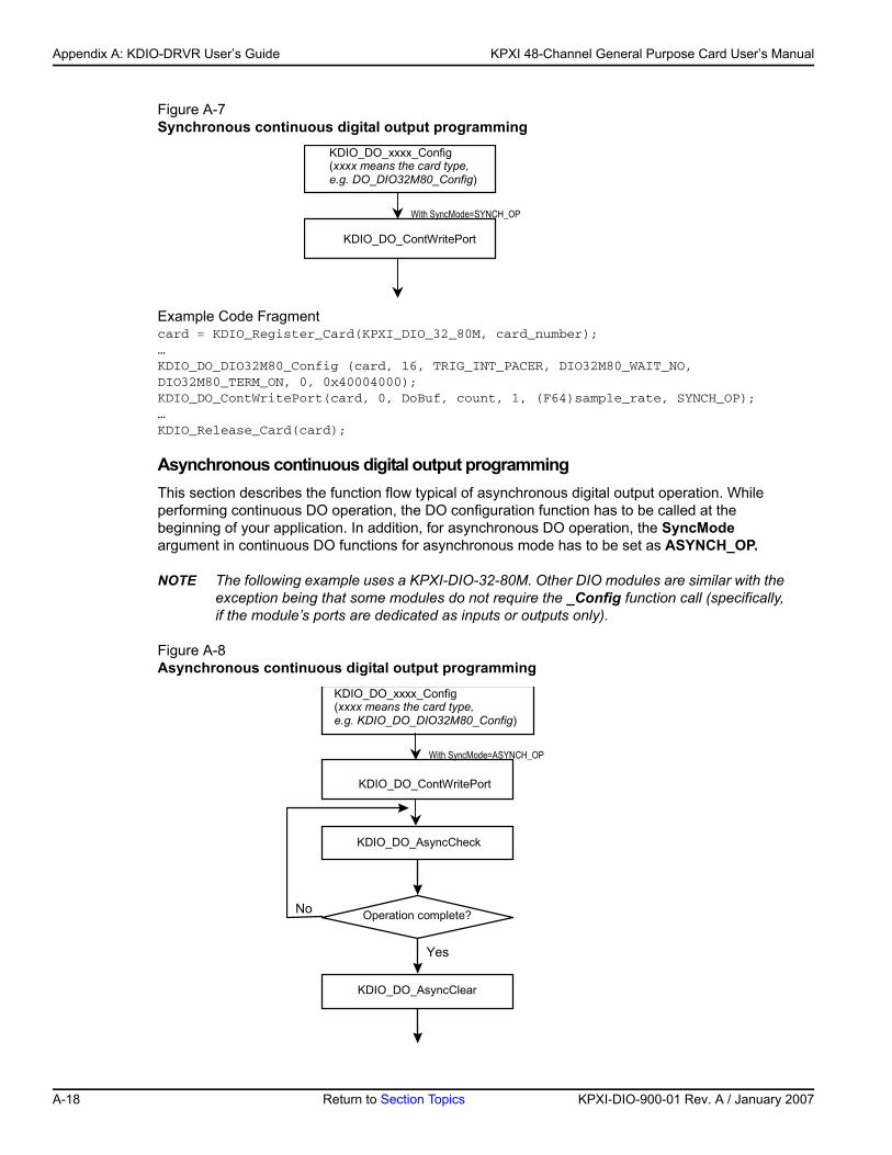
Appendix A: KDIO-DRVR User’s Guide KPXI 48-Channel General Purpose Card User’s Manual
Figure A-7Synchronous continuous digital output programming
Example Code Fragmentcard = KDIO_Register_Card(KPXI_DIO_32_80M, card_number);…KDIO_DO_DIO32M80_Config (card, 16, TRIG_INT_PACER, DIO32M80_WAIT_NO, DIO32M80_TERM_ON, 0, 0x40004000);KDIO_DO_ContWritePort(card, 0, DoBuf, count, 1, (F64)sample_rate, SYNCH_OP);…KDIO_Release_Card(card);
Asynchronous continuous digital output programmingThis section describes the function flow typical of asynchronous digital output operation. While performing continuous DO operation, the DO configuration function has to be called at the beginning of your application. In addition, for asynchronous DO operation, the SyncMode argument in continuous DO functions for asynchronous mode has to be set as ASYNCH_OP.
NOTE The following example uses a KPXI-DIO-32-80M. Other DIO modules are similar with the exception being that some modules do not require the _Config function call (specifically, if the module’s ports are dedicated as inputs or outputs only).
Figure A-8Asynchronous continuous digital output programming
KDIO_DO_xxxx_Config(xxxx means the card type,e.g. DO_DIO32M80_Config)
KDIO_DO_ContWritePort
With SyncMode=SYNCH_OP
KDIO_DO_xxxx_Config(xxxx means the card type,e.g. KDIO_DO_DIO32M80_Config)
KDIO_DO_ContWritePort
KDIO_DO_AsyncCheck
Operation complete?
Yes
No
With SyncMode=ASYNCH_OP
KDIO_DO_AsyncClear
A-18 Return to Section Topics KPXI-DIO-900-01 Rev. A / January 2007
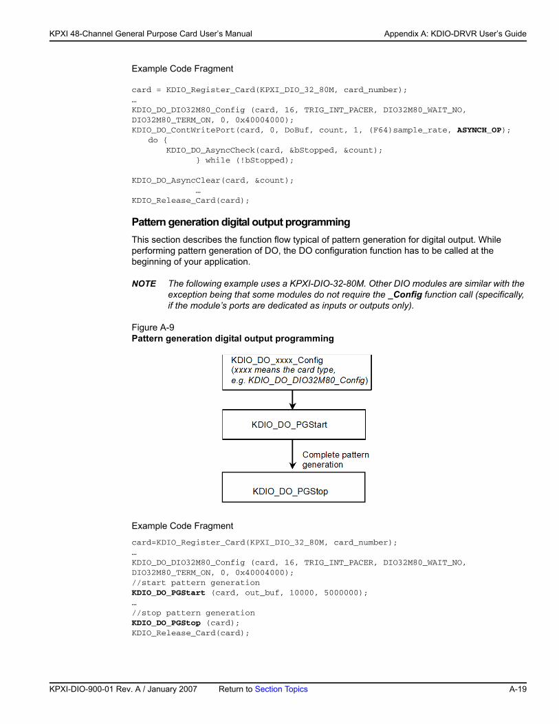
KP
KPXI 48-Channel General Purpose Card User’s Manual Appendix A: KDIO-DRVR User’s Guide
Example Code Fragment
card = KDIO_Register_Card(KPXI_DIO_32_80M, card_number);…KDIO_DO_DIO32M80_Config (card, 16, TRIG_INT_PACER, DIO32M80_WAIT_NO, DIO32M80_TERM_ON, 0, 0x40004000);KDIO_DO_ContWritePort(card, 0, DoBuf, count, 1, (F64)sample_rate, ASYNCH_OP);
do { KDIO_DO_AsyncCheck(card, &bStopped, &count); } while (!bStopped);
KDIO_DO_AsyncClear(card, &count); …KDIO_Release_Card(card);
Pattern generation digital output programming This section describes the function flow typical of pattern generation for digital output. While performing pattern generation of DO, the DO configuration function has to be called at the beginning of your application.
NOTE The following example uses a KPXI-DIO-32-80M. Other DIO modules are similar with the exception being that some modules do not require the _Config function call (specifically, if the module’s ports are dedicated as inputs or outputs only).
Figure A-9Pattern generation digital output programming
Example Code Fragment
card=KDIO_Register_Card(KPXI_DIO_32_80M, card_number);…KDIO_DO_DIO32M80_Config (card, 16, TRIG_INT_PACER, DIO32M80_WAIT_NO, DIO32M80_TERM_ON, 0, 0x40004000);//start pattern generation KDIO_DO_PGStart (card, out_buf, 10000, 5000000); …//stop pattern generationKDIO_DO_PGStop (card);KDIO_Release_Card(card);
XI-DIO-900-01 Rev. A / January 2007 Return to Section Topics A-19
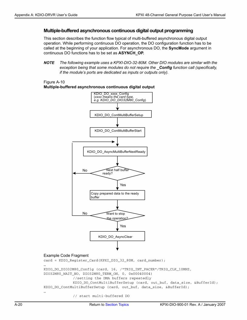
Appendix A: KDIO-DRVR User’s Guide KPXI 48-Channel General Purpose Card User’s Manual
Multiple-buffered asynchronous continuous digital output programming This section describes the function flow typical of multi-buffered asynchronous digital output operation. While performing continuous DO operation, the DO configuration function has to be called at the beginning of your application. For asynchronous DO, the SyncMode argument in continuous DO functions has to be set as ASYNCH_OP.
NOTE The following example uses a KPXI-DIO-32-80M. Other DIO modules are similar with the exception being that some modules do not require the _Config function call (specifically, if the module’s ports are dedicated as inputs or outputs only).
Figure A-10Multiple-buffered asynchronous continuous digital output
Example Code Fragmentcard = KDIO_Register_Card(KPXI_DIO_32_80M, card_number);…KDIO_DO_DIO32M80_Config (card, 16, /*TRIG_INT_PACER*/TRIG_CLK_10MHZ, DIO32M80_WAIT_NO, DIO32M80_TERM_ON, 0, 0x00040004)
//setting the DMA buffers repeatedlyKDIO_DO_ContMultiBufferSetup (card, out_buf, data_size, &BufferId);
KDIO_DO_ContMultiBufferSetup (card, out_buf, data_size, &BufferId);… // start multi-buffered DO
KDIO_DO_xxxx_Config(xxxx means the card type,e.g. KDIO_DO_DIO32M80_Config)
KDIO_DO_ContMultiBufferStart
KDIO_DO_AsyncMultiBufferNextReady
Next half bufferready?
Yes
No
KDIO_DO_ContMultiBufferSetup
Copy prepared data to the readybuffer
Want to stopthe operation?
KDIO_DO_AsyncClear
Yes
No
A-20 Return to Section Topics KPXI-DIO-900-01 Rev. A / January 2007
KP
KPXI 48-Channel General Purpose Card User’s Manual Appendix A: KDIO-DRVR User’s Guide
KDIO_DO_ContMultiBufferStart (card, 0, 1);do {
do { KDIO_DI_AsyncMultiBufferNextReady(card, &HalfReady, &viewidx); } while (!HalfReady);
// Copy prepared data to the ready buffer} while (!clear_op);KDIO_DO_AsyncClear(card, &count); …KDIO_Release_Card(card);
DAQ event message programming hintsDAQ Event Message functions are an efficient way to monitor your background data acquisition processes, without dedicating your foreground process for status checking. There are two kinds of events, which are DI/DO operation completeness notification event and buffer ready notification event.
To receive notification from the KDIO-DRVR data acquisition process in case of special events, you can call KDIO_DI_EventCallBack, or KDIO_DO_EventCallBack to specify an event in which you are interested.
Event notification is done through user-defined callbacks. When a user-specified DAQ event occurs, KDIO-DRVR calls the user-defined callback. After receiving the message, the user’s application can carry out the appropriate task.
The event message mechanism is easy and safe in Windows systems; however, the time delay between the event and notification is highly variable and depends largely on how loaded your system is. In addition, if a callback function is called, succeeding events will not be handled until your callback has returned. If the time interval between events is smaller than the time taken for callback function processing, the succeeding events will not be handled. Therefore this mechanism is not suitable for the frequent events occurrence condition.
NOTE The following example uses a KPXI-DIO-32-80M. Other DIO modules are similar with the exception being that some modules do not require the _Config function call (specifically, if the module’s ports are dedicated as inputs or outputs only).
Example Code Fragment
card = KDIO_Register_Card(KPXI_DIO_32_80M, card_number);KDIO_DI_DIO32M80_Config(card, 16, TRIG_CLK_10MHZ, DIO32M80_WAIT_NO, DIO32M80_TERM_ON, 0, 0, 0);
// Enable half buffer ready event notificationKDIO_DI_EventCallBack (card, 1, DBEvent, (U32) DI_DBCallBack );
//Enable DI completeness event notificationKDIO_DI_EventCallBack (card, 1, DIEnd, (U32) DI_CallBack );
KDIO_DI_ContMultiBufferStart (card, 0, 1);....KDIO_Release_Card(card);
//Half buffer ready call back functionvoid DI_DBCallBack(){//half buffer is readyKDIO_DI_AsyncDblBufferTransfer(card, &HalfReady, &viewidx);….
XI-DIO-900-01 Rev. A / January 2007 Return to Section Topics A-21
Appendix A: KDIO-DRVR User’s Guide KPXI 48-Channel General Purpose Card User’s Manual
}
//DI completeness call back functionvoid DI_CallBack (){//DI is completed ]KDIO_DO_AsyncClear (card, &count);….}
Interrupt event message programming hintsKDIO-DRVR provides two methods to perform interrupt occurrence notification for Keithley PXI DIO cards that have dual interrupt system.
The Event Message method handles event notification through user-defined callbacks and/or the Windows Message queue (for VB5, through user-defined callbacks only). When a user-specified interrupt event occurs, KDIO-DRVR calls the user-defined callback (if defined) and/or puts a message into the Windows Message queue, if you specified a window handle. After receiving the message, the user’s application can carry out the appropriate task.
The event message mechanism is easy and safe in Windows systems; however, the time delay between the event and notification is highly variable and depends largely on how loaded your system is. In addition, if a callback function is called, succeeding events will not be handled until your callback has returned. If the time interval between interrupt events is smaller than the time taken for callback function processing, the succeeding interrupt events will not be handled. Therefore this mechanism is not suitable for the frequent interrupt occurrence condition.
The Event Status checking and waiting method handles interrupt event status checking through Win32 wait functions, such as WaitForSingleObject or WaitForMultipleObjects. This method is useful for the situation that the interrupt event occurs very often, and the applications written in the language that doesn’t support function pointers (e.g. VB4).
1. Through user-defined callbacks and the Windows Message queue
Example Code Fragment
card = KDIO_Register_Card(KPXI-DIO-16-16, card_number);
//INT1 event notification is through window messageKDIO_INT1_EventMessage (card, INT1_EXT_SIGNAL, hWnd, WM_INT, NULL);
//INT2 event notification is through a callback functionKDIO_INT2_EventMessage (card, INT2_EXT_SIGNAL, hWnd, NULL, (void *) cbfn);….//window message handling functionlong PASCAL MainWndProc(hWnd, message, wParam, lParam){ switch(message) { ….
case WM_INT: //interrupt event occurring message ….
break; …. case WM_DESTROY://Disable interrupts
KDIO_INT1_EventMessage (card, INT1_DISABLE, hMainWnd, NULL, NULL);KDIO_INT2_EventMessage (card, INT2_DISABLE, hMainWnd, NULL, NULL);
//Release cardif (card >= 0) KDIO_Release_Card(card);
A-22 Return to Section Topics KPXI-DIO-900-01 Rev. A / January 2007
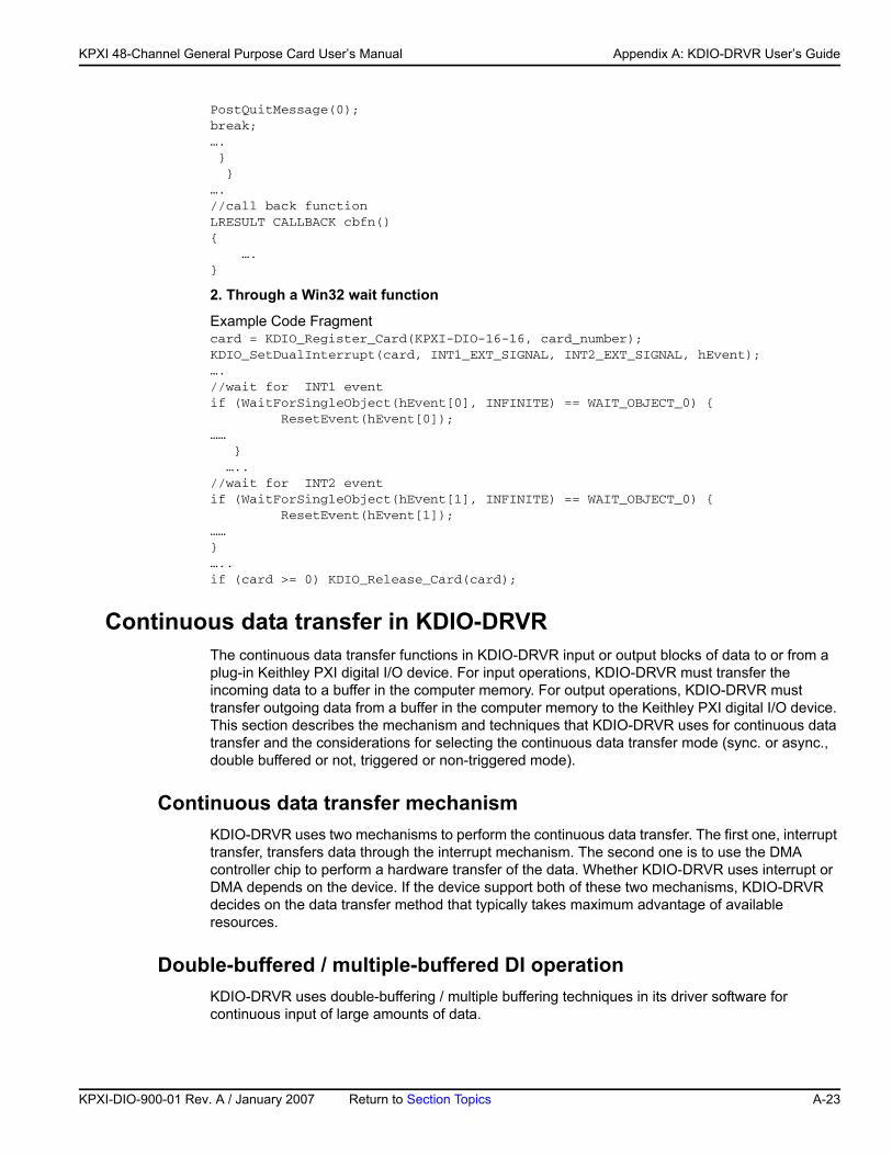
KP
KPXI 48-Channel General Purpose Card User’s Manual Appendix A: KDIO-DRVR User’s Guide
PostQuitMessage(0);break;…. } }….//call back functionLRESULT CALLBACK cbfn(){ ….}
2. Through a Win32 wait function
Example Code Fragmentcard = KDIO_Register_Card(KPXI-DIO-16-16, card_number);KDIO_SetDualInterrupt(card, INT1_EXT_SIGNAL, INT2_EXT_SIGNAL, hEvent);….//wait for INT1 eventif (WaitForSingleObject(hEvent[0], INFINITE) == WAIT_OBJECT_0) { ResetEvent(hEvent[0]);…… } …..//wait for INT2 eventif (WaitForSingleObject(hEvent[1], INFINITE) == WAIT_OBJECT_0) { ResetEvent(hEvent[1]);……}…..if (card >= 0) KDIO_Release_Card(card);
Continuous data transfer in KDIO-DRVRThe continuous data transfer functions in KDIO-DRVR input or output blocks of data to or from a plug-in Keithley PXI digital I/O device. For input operations, KDIO-DRVR must transfer the incoming data to a buffer in the computer memory. For output operations, KDIO-DRVR must transfer outgoing data from a buffer in the computer memory to the Keithley PXI digital I/O device. This section describes the mechanism and techniques that KDIO-DRVR uses for continuous data transfer and the considerations for selecting the continuous data transfer mode (sync. or async., double buffered or not, triggered or non-triggered mode).
Continuous data transfer mechanismKDIO-DRVR uses two mechanisms to perform the continuous data transfer. The first one, interrupt transfer, transfers data through the interrupt mechanism. The second one is to use the DMA controller chip to perform a hardware transfer of the data. Whether KDIO-DRVR uses interrupt or DMA depends on the device. If the device support both of these two mechanisms, KDIO-DRVR decides on the data transfer method that typically takes maximum advantage of available resources.
Double-buffered / multiple-buffered DI operationKDIO-DRVR uses double-buffering / multiple buffering techniques in its driver software for continuous input of large amounts of data.
XI-DIO-900-01 Rev. A / January 2007 Return to Section Topics A-23
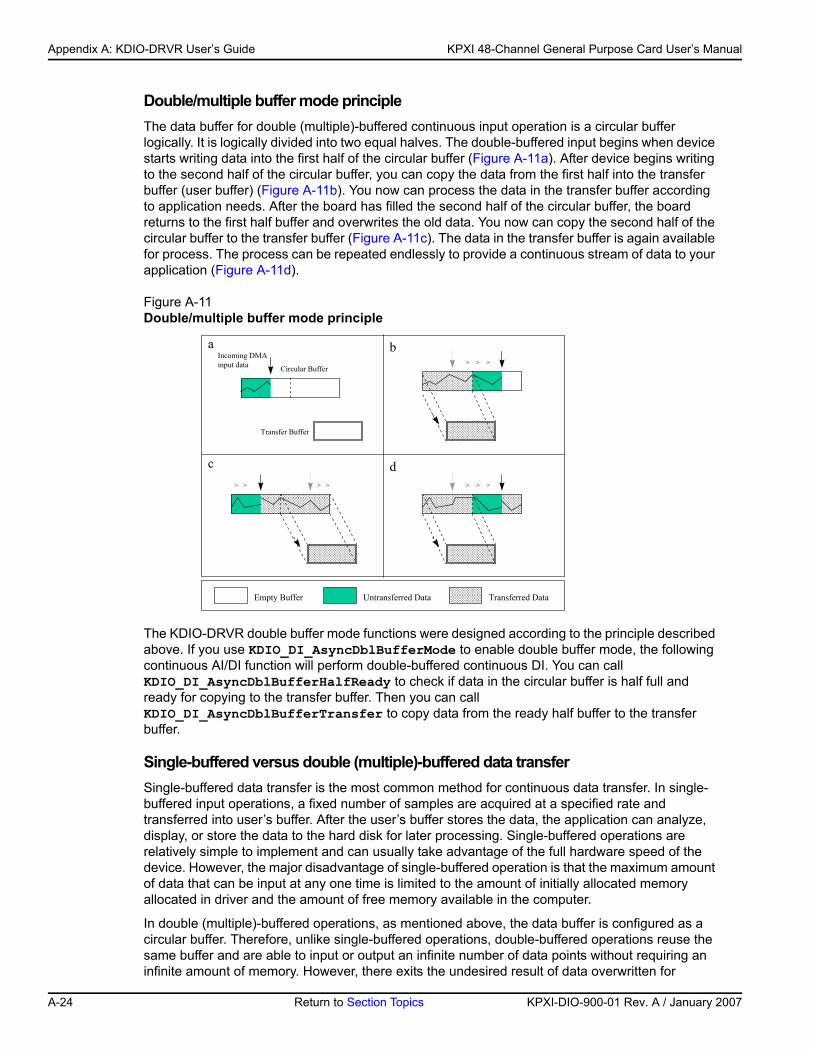
Appendix A: KDIO-DRVR User’s Guide KPXI 48-Channel General Purpose Card User’s Manual
Double/multiple buffer mode principleThe data buffer for double (multiple)-buffered continuous input operation is a circular buffer logically. It is logically divided into two equal halves. The double-buffered input begins when device starts writing data into the first half of the circular buffer (Figure A-11a). After device begins writing to the second half of the circular buffer, you can copy the data from the first half into the transfer buffer (user buffer) (Figure A-11b). You now can process the data in the transfer buffer according to application needs. After the board has filled the second half of the circular buffer, the board returns to the first half buffer and overwrites the old data. You now can copy the second half of the circular buffer to the transfer buffer (Figure A-11c). The data in the transfer buffer is again available for process. The process can be repeated endlessly to provide a continuous stream of data to your application (Figure A-11d).
Figure A-11Double/multiple buffer mode principle
The KDIO-DRVR double buffer mode functions were designed according to the principle described above. If you use KDIO_DI_AsyncDblBufferMode to enable double buffer mode, the following continuous AI/DI function will perform double-buffered continuous DI. You can call KDIO_DI_AsyncDblBufferHalfReady to check if data in the circular buffer is half full and ready for copying to the transfer buffer. Then you can call KDIO_DI_AsyncDblBufferTransfer to copy data from the ready half buffer to the transfer buffer.
Single-buffered versus double (multiple)-buffered data transferSingle-buffered data transfer is the most common method for continuous data transfer. In single-buffered input operations, a fixed number of samples are acquired at a specified rate and transferred into user’s buffer. After the user’s buffer stores the data, the application can analyze, display, or store the data to the hard disk for later processing. Single-buffered operations are relatively simple to implement and can usually take advantage of the full hardware speed of the device. However, the major disadvantage of single-buffered operation is that the maximum amount of data that can be input at any one time is limited to the amount of initially allocated memory allocated in driver and the amount of free memory available in the computer.
In double (multiple)-buffered operations, as mentioned above, the data buffer is configured as a circular buffer. Therefore, unlike single-buffered operations, double-buffered operations reuse the same buffer and are able to input or output an infinite number of data points without requiring an infinite amount of memory. However, there exits the undesired result of data overwritten for
Incoming DMAinput data Circular Buffer
Transfer Buffer
a b
c d
> > >
> > >> >
Empty Buffer Untransferred Data Transferred Data
> >
A-24 Return to Section Topics KPXI-DIO-900-01 Rev. A / January 2007
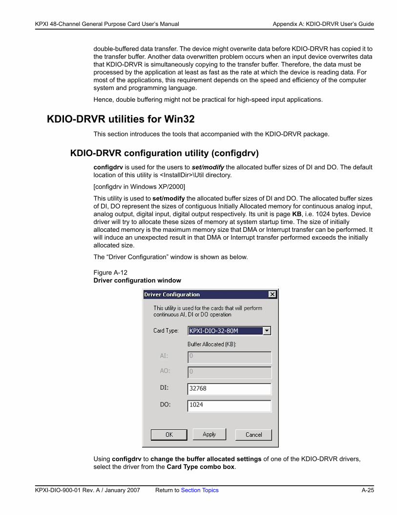
KP
KPXI 48-Channel General Purpose Card User’s Manual Appendix A: KDIO-DRVR User’s Guide
double-buffered data transfer. The device might overwrite data before KDIO-DRVR has copied it to the transfer buffer. Another data overwritten problem occurs when an input device overwrites data that KDIO-DRVR is simultaneously copying to the transfer buffer. Therefore, the data must be processed by the application at least as fast as the rate at which the device is reading data. For most of the applications, this requirement depends on the speed and efficiency of the computer system and programming language.
Hence, double buffering might not be practical for high-speed input applications.
KDIO-DRVR utilities for Win32This section introduces the tools that accompanied with the KDIO-DRVR package.
KDIO-DRVR configuration utility (configdrv)configdrv is used for the users to set/modify the allocated buffer sizes of DI and DO. The default location of this utility is <InstallDir>\Util directory.
[configdrv in Windows XP/2000]
This utility is used to set/modify the allocated buffer sizes of DI and DO. The allocated buffer sizes of DI, DO represent the sizes of contiguous Initially Allocated memory for continuous analog input, analog output, digital input, digital output respectively. Its unit is page KB, i.e. 1024 bytes. Device driver will try to allocate these sizes of memory at system startup time. The size of initially allocated memory is the maximum memory size that DMA or Interrupt transfer can be performed. It will induce an unexpected result in that DMA or Interrupt transfer performed exceeds the initially allocated size.
The “Driver Configuration” window is shown as below.
Figure A-12Driver configuration window
Using configdrv to change the buffer allocated settings of one of the KDIO-DRVR drivers, select the driver from the Card Type combo box.
�������������
� �
���
�
�
���
���
���
���
�������
XI-DIO-900-01 Rev. A / January 2007 Return to Section Topics A-25
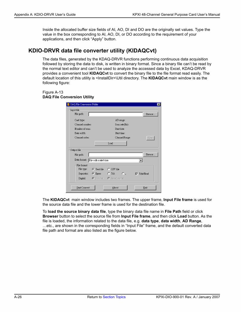
Appendix A: KDIO-DRVR User’s Guide KPXI 48-Channel General Purpose Card User’s Manual
Inside the allocated buffer size fields of AI, AO, DI and DO are the originally set values. Type the value in the box corresponding to AI, AO, DI, or DO according to the requirement of your applications, and then click “Apply” button.
KDIO-DRVR data file converter utility (KIDAQCvt)The data files, generated by the KDAQ-DRVR functions performing continuous data acquisition followed by storing the data to disk, is written in binary format. Since a binary file can’t be read by the normal text editor and can’t be used to analyze the accessed data by Excel, KDAQ-DRVR provides a convenient tool KIDAQCvt to convert the binary file to the file format read easily. The default location of this utility is <InstallDir>\Util directory. The KIDAQCvt main window is as the following figure:
Figure A-13DAQ File Conversion Utility
The KIDAQCvt main window includes two frames. The upper frame, Input File frame is used for the source data file and the lower frame is used for the destination file.
To load the source binary data file, type the binary data file name in File Path field or click Browser button to select the source file from Input File frame, and then click Load button. As the file is loaded, the information related to the data file, e.g. data type, data width, AD Range, …etc., are shown in the corresponding fields in “Input File” frame, and the default converted data file path and format are also listed as the figure below.
A-26 Return to Section Topics KPXI-DIO-900-01 Rev. A / January 2007
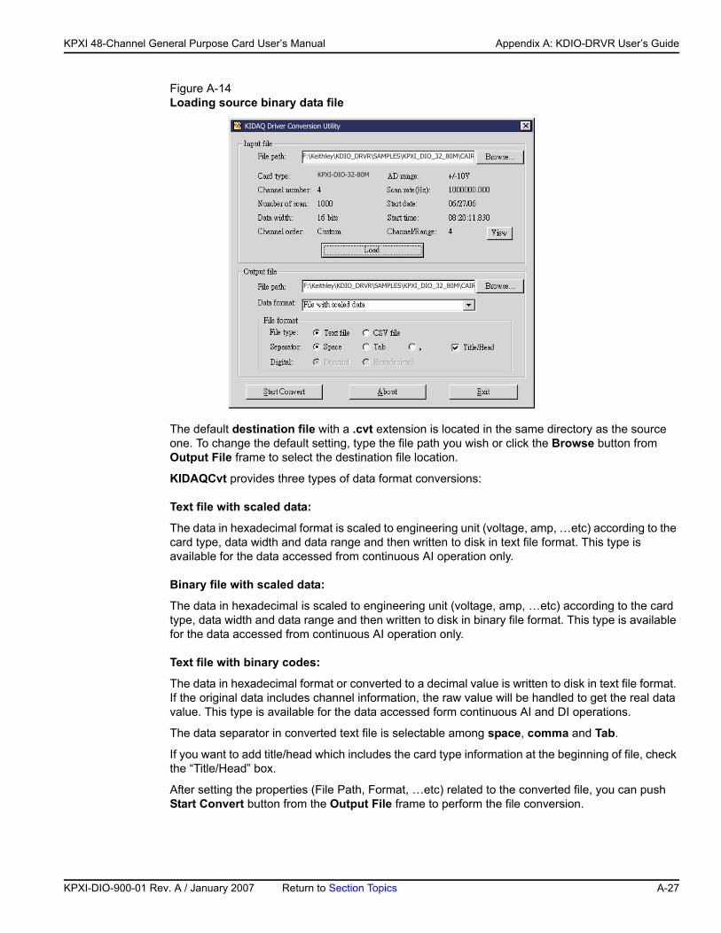
KP
KPXI 48-Channel General Purpose Card User’s Manual Appendix A: KDIO-DRVR User’s Guide
Figure A-14Loading source binary data file
The default destination file with a .cvt extension is located in the same directory as the source one. To change the default setting, type the file path you wish or click the Browse button from Output File frame to select the destination file location.
KIDAQCvt provides three types of data format conversions:
Text file with scaled data:
The data in hexadecimal format is scaled to engineering unit (voltage, amp, …etc) according to the card type, data width and data range and then written to disk in text file format. This type is available for the data accessed from continuous AI operation only.
Binary file with scaled data:
The data in hexadecimal is scaled to engineering unit (voltage, amp, …etc) according to the card type, data width and data range and then written to disk in binary file format. This type is available for the data accessed from continuous AI operation only.
Text file with binary codes:
The data in hexadecimal format or converted to a decimal value is written to disk in text file format. If the original data includes channel information, the raw value will be handled to get the real data value. This type is available for the data accessed form continuous AI and DI operations.
The data separator in converted text file is selectable among space, comma and Tab.
If you want to add title/head which includes the card type information at the beginning of file, check the “Title/Head” box.
After setting the properties (File Path, Format, …etc) related to the converted file, you can push Start Convert button from the Output File frame to perform the file conversion.
���������������� �!"!�#���$%#����� ��� � ���&��!
�������������
����'(���)��(&�*)��+��*(,������
���������������� �!"!�#���$%#����� ��� � ���&��!
XI-DIO-900-01 Rev. A / January 2007 Return to Section Topics A-27
Appendix A: KDIO-DRVR User’s Guide KPXI 48-Channel General Purpose Card User’s Manual
This page left blank intentionally.
A-28 Return to Section Topics KPXI-DIO-900-01 Rev. A / January 2007
Appendix B KDIO-DRVR Function Reference
In this appendix:Topic Page
Function description .................................................................... B-2Data types ............................................................................. B-2Function reference ................................................................ B-2
Status Codes ............................................................................. B-38
Data file format .......................................................................... B-40Header ................................................................................ B-40ChannelRange .................................................................... B-41Data Block........................................................................... B-42
Function Support ....................................................................... B-43
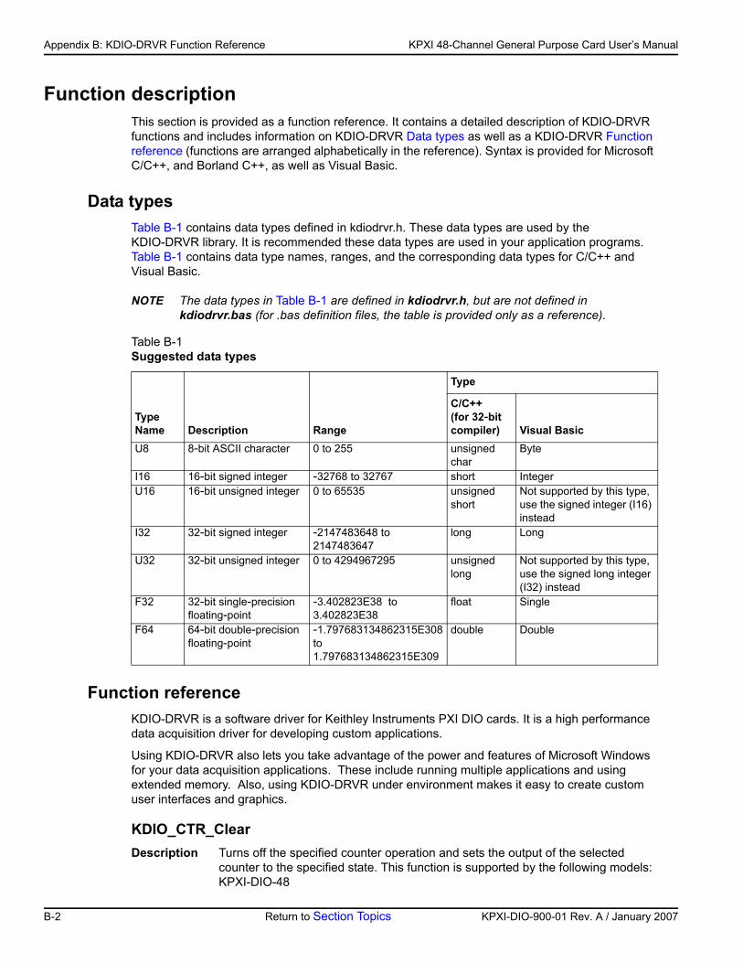
Appendix B: KDIO-DRVR Function Reference KPXI 48-Channel General Purpose Card User’s Manual
Function descriptionThis section is provided as a function reference. It contains a detailed description of KDIO-DRVR functions and includes information on KDIO-DRVR Data types as well as a KDIO-DRVR Function reference (functions are arranged alphabetically in the reference). Syntax is provided for Microsoft C/C++, and Borland C++, as well as Visual Basic.
Data types Table B-1 contains data types defined in kdiodrvr.h. These data types are used by the KDIO-DRVR library. It is recommended these data types are used in your application programs. Table B-1 contains data type names, ranges, and the corresponding data types for C/C++ and Visual Basic.
NOTE The data types in Table B-1 are defined in kdiodrvr.h, but are not defined in kdiodrvr.bas (for .bas definition files, the table is provided only as a reference).
Function referenceKDIO-DRVR is a software driver for Keithley Instruments PXI DIO cards. It is a high performance data acquisition driver for developing custom applications.
Using KDIO-DRVR also lets you take advantage of the power and features of Microsoft Windows for your data acquisition applications. These include running multiple applications and using extended memory. Also, using KDIO-DRVR under environment makes it easy to create custom user interfaces and graphics.
KDIO_CTR_ClearDescription Turns off the specified counter operation and sets the output of the selected
counter to the specified state. This function is supported by the following models: KPXI-DIO-48
Table B-1Suggested data types
Type Name Description Range
Type
C/C++ (for 32-bit compiler) Visual Basic
U8 8-bit ASCII character 0 to 255 unsigned char
Byte
I16 16-bit signed integer -32768 to 32767 short IntegerU16 16-bit unsigned integer 0 to 65535 unsigned
shortNot supported by this type, use the signed integer (I16) instead
I32 32-bit signed integer -2147483648 to 2147483647
long Long
U32 32-bit unsigned integer 0 to 4294967295 unsigned long
Not supported by this type, use the signed long integer (I32) instead
F32 32-bit single-precision floating-point
-3.402823E38 to 3.402823E38
float Single
F64 64-bit double-precision floating-point
-1.797683134862315E308 to 1.797683134862315E309
double Double
B-2 Return to Section Topics KPXI-DIO-900-01 Rev. A / January 2007
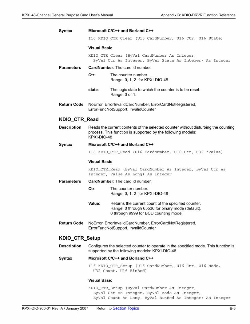
KP
KPXI 48-Channel General Purpose Card User’s Manual Appendix B: KDIO-DRVR Function Reference
Syntax Microsoft C/C++ and Borland C++
I16 KDIO_CTR_Clear (U16 CardNumber, U16 Ctr, U16 State)
Visual Basic
KDIO_CTR_Clear (ByVal CardNumber As Integer, ByVal Ctr As Integer, ByVal State As Integer) As Integer
Parameters CardNumber: The card id number.
Ctr: The counter number. Range: 0, 1, 2 for KPXI-DIO-48
state: The logic state to which the counter is to be reset. Range: 0 or 1.
Return Code NoError, ErrorInvalidCardNumber, ErrorCardNotRegistered, ErrorFuncNotSupport, InvalidCounter
KDIO_CTR_ReadDescription Reads the current contents of the selected counter without disturbing the counting
process. This function is supported by the following models: KPXI-DIO-48
Syntax Microsoft C/C++ and Borland C++
I16 KDIO_CTR_Read (U16 CardNumber, U16 Ctr, U32 *Value)
Visual Basic
KDIO_CTR_Read (ByVal CardNumber As Integer, ByVal Ctr As Integer, Value As Long) As Integer
Parameters CardNumber: The card id number.
Ctr: The counter number. Range: 0, 1, 2 for KPXI-DIO-48
Value: Returns the current count of the specified counter. Range: 0 through 65536 for binary mode (default). 0 through 9999 for BCD counting mode.
Return Code NoError, ErrorInvalidCardNumber, ErrorCardNotRegistered, ErrorFuncNotSupport, InvalidCounter
KDIO_CTR_SetupDescription Configures the selected counter to operate in the specified mode. This function is
supported by the following models: KPXI-DIO-48
Syntax Microsoft C/C++ and Borland C++
I16 KDIO_CTR_Setup (U16 CardNumber, U16 Ctr, U16 Mode, U32 Count, U16 BinBcd)
Visual Basic
KDIO_CTR_Setup (ByVal CardNumber As Integer, ByVal Ctr As Integer, ByVal Mode As Integer, ByVal Count As Long, ByVal BinBcd As Integer) As Integer
XI-DIO-900-01 Rev. A / January 2007 Return to Section Topics B-3
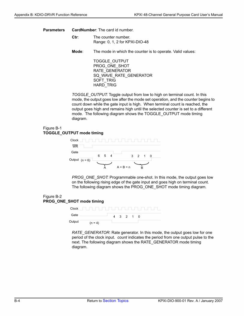
Appendix B: KDIO-DRVR Function Reference KPXI 48-Channel General Purpose Card User’s Manual
Parameters CardNumber: The card id number.
Ctr: The counter number. Range: 0, 1, 2 for KPXI-DIO-48
Mode: The mode in which the counter is to operate. Valid values:
TOGGLE_OUTPUT PROG_ONE_SHOT RATE_GENERATOR SQ_WAVE_RATE_GENERATOR SOFT_TRIG HARD_TRIG
TOGGLE_OUTPUT: Toggle output from low to high on terminal count. In this mode, the output goes low after the mode set operation, and the counter begins to count down while the gate input is high. When terminal count is reached, the output goes high and remains high until the selected counter is set to a different mode. The following diagram shows the TOGGLE_OUTPUT mode timing diagram.
Figure B-1TOGGLE_OUTPUT mode timing
PROG_ONE_SHOT: Programmable one-shot. In this mode, the output goes low on the following rising edge of the gate input and goes high on terminal count. The following diagram shows the PROG_ONE_SHOT mode timing diagram.
Figure B-2PROG_ONE_SHOT mode timing
RATE_GENERATOR: Rate generator. In this mode, the output goes low for one period of the clock input. count indicates the period from one output pulse to the next. The following diagram shows the RATE_GENERATOR mode timing diagram.
Clock
WR
Gate
Output6 5 4 3 2 1 0
(n = 6)
A BA + B = n
Clock
Gate
Output4 3 2 1 0
(n = 4)
B-4 Return to Section Topics KPXI-DIO-900-01 Rev. A / January 2007
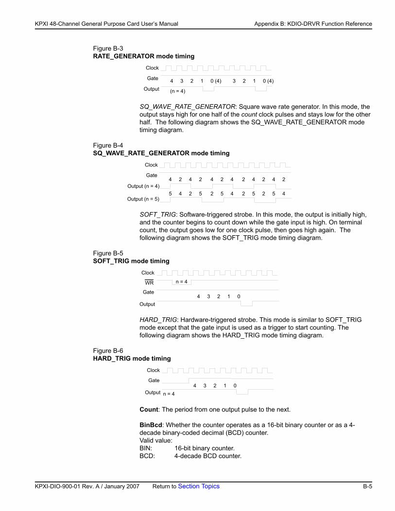
KP
KPXI 48-Channel General Purpose Card User’s Manual Appendix B: KDIO-DRVR Function Reference
Figure B-3RATE_GENERATOR mode timing
SQ_WAVE_RATE_GENERATOR: Square wave rate generator. In this mode, the output stays high for one half of the count clock pulses and stays low for the other half. The following diagram shows the SQ_WAVE_RATE_GENERATOR mode timing diagram.
Figure B-4SQ_WAVE_RATE_GENERATOR mode timing
SOFT_TRIG: Software-triggered strobe. In this mode, the output is initially high, and the counter begins to count down while the gate input is high. On terminal count, the output goes low for one clock pulse, then goes high again. The following diagram shows the SOFT_TRIG mode timing diagram.
Figure B-5SOFT_TRIG mode timing
HARD_TRIG: Hardware-triggered strobe. This mode is similar to SOFT_TRIG mode except that the gate input is used as a trigger to start counting. The following diagram shows the HARD_TRIG mode timing diagram.
Figure B-6HARD_TRIG mode timing
Count: The period from one output pulse to the next.
BinBcd: Whether the counter operates as a 16-bit binary counter or as a 4-decade binary-coded decimal (BCD) counter. Valid value: BIN: 16-bit binary counter. BCD: 4-decade BCD counter.
Clock
Gate
Output4 3 2 1 0 (4) 3 2 1 0 (4)
(n = 4)
Clock
Gate
Output (n = 4)4 2 4 2 4 2 4 2 4 2 4 2
Output (n = 5)5 4 2 5 2 5 4 2 5 2 5 4
Clock
WR
Gate
Output4 3 2 1 0
n = 4
Clock
Gate
Output4 3 2 1 0
n = 4
XI-DIO-900-01 Rev. A / January 2007 Return to Section Topics B-5
Appendix B: KDIO-DRVR Function Reference KPXI 48-Channel General Purpose Card User’s Manual
Return Code NoError, ErrorInvalidCardNumber, ErrorCardNotRegistered, ErrorFuncNotSupport, InvalidCounter
KDIO_CTR_UpdateDescription A new initial count is written to the selected counter without affecting the counter’s
progrmmed mode. This function is supported by the following models: KPXI-DIO-48
Syntax Microsoft C/C++ and Borland C++
I16 KDIO_CTR_Update (U16 CardNumber, U16 Ctr, U32 Count)
Visual Basic
KDIO_CTR_Update (ByVal CardNumber As Integer, ByVal Ctr As Integer, ByVal count As Long) As Integer
Parameters CardNumber: The card id number.
Ctr: The counter number.
Range: 0, 1, 2 for KPXI-DIO-48
count: the new count for the specified counter. Range: 0 through 65536 for binary mode (default). 0 through 9999 for BCD counting mode.
Return Code NoError, ErrorInvalidCardNumber, ErrorCardNotRegistered, ErrorFuncNotSupport, InvalidCounter
KDIO_DI_DIO32M80_ConfigDescription Informs KDIO-DRVR library of the trigger source, port width, etc. selected for
KPXI-DIO-32-80M card with card ID CardNumber. You must call this function before calling function to perform continuous digital input operation. This function is supported by the following models: KPXI-DIO-32-80M
Syntax Microsoft C/C++ and Borland C++
I16 KDIO_DI_DIO32M80_Config (U16 CardNumber, U16 PortWidth, U16 TrigSource, U16 WaitStatus, U16 Terminator, U16 I_Cntrl_Pol, BOOLEAN ClearFifo, BOOLEAN DisableDI)
Visual Basic
KDIO_DI_DIO32M80_Config (ByVal CardNumber As Integer, ByVal PortWidth As Integer, ByVal TrigSource As Integer, ByVal WaitStatus As Integer, ByVal Terminator As Integer, ByVal I_Cntrl_Pol As Integer, ByVal ClearFifo As Byte, ByVal DisableDI As Byte) As Integer
Parameters CardNumber: The card id number.
PortWidth: The width of digital input port (PORT A). The valid value is 0, 8, 16, or 32.
TrigSource: The trigger mode for continuous digital input.
Valid values: TRIG_INT_PACER: on-board programmable pacer timer
B-6 Return to Section Topics KPXI-DIO-900-01 Rev. A / January 2007
KP
KPXI 48-Channel General Purpose Card User’s Manual Appendix B: KDIO-DRVR Function Reference
TRIG_EXT_STROBE: external signal trigger TRIG_HANDSHAKE: handshaking TRIG_CLK_10MHz: 10MHz clock TRIG_CLK_20MHz: 20MHz clock
WaitStatus: DI Wait Trigger Status. Valid values are: DIO32M80_WAIT_NO: input sampling starts immediately DIO32M80_WAIT_TRG: digital input sampling waits rising or falling edge of I_TRG to start DI
Terminator: PortA Terminator On/Off. Valid values: DIO32M80_TERM_ON: terminator on DIO32M80_TERM_OFF: terminator off
I_Cntrl_Pol: The polarity configuration. This argument is an integer expression formed from one or more of the manifest constants defined in kdiodrvr.h. There are three groups of constants:
(1) DIREQ DIO32M80_DIREQ_POS: DIREQ signal is rising edge active DIO32M80_DIREQ_NEG: DIREQ signal is falling edge active
(2) DIACK DIO32M80_DIACK_POS: DIACK signal is rising edge active DIO32M80_DIACK_NEG: DIACK signal is falling edge active
(3) DITRIG DIO32M80_DITRIG_POS: DITRIG signal is rising edge active DIO32M80_DITRIG_NEG: DITRIG signal is falling edge active
ClearFifo: FALSE: retain the FIFO data TRUE: clear FIFO data before perform digital input
DisableDI: FALSE: digital input operation still active after DMA transfer complete. The input data still put into FIFO
TRUE: disable digital input operation immediately when DMA transfer complete
Return Code NoError, ErrorInvalidCardNumber, ErrorCardNotRegistered, ErrorFuncNotSupport
KDIO_DI_AsyncCheckDescription Check the current status of the asynchronous digital input operation. This function
is supported by the following models: KPXI-DIO-32-80M
Syntax Microsoft C/C++ and Borland C++
I16 KDIO_DI_AsyncCheck (U16 CardNumber, BOOLEAN *Stopped, U32 *AccessCnt)
Visual Basic
KDIO_DI_AsyncCheck (ByVal CardNumber As Integer, Stopped As Byte, AccessCnt As Long) As Integer
XI-DIO-900-01 Rev. A / January 2007 Return to Section Topics B-7
Appendix B: KDIO-DRVR Function Reference KPXI 48-Channel General Purpose Card User’s Manual
Parameters CardNumber: The card id of the card that performs the asynchronous operation.
Stopped: Whether the asynchronous analog input operation has completed. If Stopped = TRUE, the digital input operation has stopped. Either the number of digital input indicated in the call that initiated the asynchronous digital input operation has completed or an error has occurred. If Stopped = FALSE, the operation is not yet complete. (constants TRUE and FALSE are defined in kdiodrvr.h)
AccessCnt: The number of digital input data that has been transferred at the time the call to KDIO_DI_AsyncCheck(). AccessCnt is of no use (always returns 0) in KDIO_DI_AsyncCheck() and KDIO_ DI_AsyncClear() with KPXI-DIO-32-80M board because on-board chip (PLX9080) of KPXI-DIO-32-80M has no function or register to get the current amount of DMA transfer.
Return Code NoError, ErrorInvalidCardNumber, ErrorCardNotRegistered, ErrorFuncNotSupport
KDIO_DI_AsyncClearDescription Stop the asynchronous digital input operation. This function is supported by the
following models: KPXI-DIO-32-80M
Syntax Microsoft C/C++ and Borland C++
I16 KDIO_DI_AsyncClear (U16 CardNumber, U32 *AccessCnt)
Visual Basic
KDIO_DI_AsyncClear (ByVal CardNumber As Integer, AccessCnt As Long) As Integer
Parameters CardNumber: The card id of the card that performs the asynchronous operation.
AccessCnt: The number of digital input data that has been transferred at the time the call to KDIO_DI_AsyncClear().
If double-buffered mode is enabled, AccessCnt returns the next position after the position the last data is stored in the circular buffer. If the AccessCnt exceeds the half size of circular buffer, call "KIO_DI_AsyncDblBufferTransfer " twice to get the data. AccessCnt is of no use (always returns 0) in KDIO_DI_AsyncCheck() andKDIO_DI_AsyncClear() with KPXI-DIO-32-80M board because on-board chip (PLX9080) of KPXI-DIO-32-80M has no function or register to get the current amount of DMA transfer.
Return Code NoError, ErrorInvalidCardNumber, ErrorCardNotRegistered, ErrorFuncNotSupport
KDIO_DI_AsyncDblBufferOverrunDescription Checks or clears overrun status of the double-buffered/multi-buffered digital input
operation. This function is supported by the following models: KPXI-DIO-32-80M
Syntax Microsoft C/C++ and Borland C++
I16 KDIO_DI_AsyncDblBufferOverrun (U16 CardNumber, U16 op, U16 *overrunFlag)
B-8 Return to Section Topics KPXI-DIO-900-01 Rev. A / January 2007
KP
KPXI 48-Channel General Purpose Card User’s Manual Appendix B: KDIO-DRVR Function Reference
Visual Basic
KDIO_DI_AsyncDblBufferOverrun (ByVal CardNumber As Integer, ByVal op As Integer, overrunFlag As Integer) As Integer
Parameters CardNumber: The card id of the card that double-buffered mode to be set.
op: check/clear overrun status/flag. 0: check the overrun status. 1: clear the overrun flag.
overrunFlag: returned overrun status 0: no overrun occurs. 1: overrun occurs.
Return Code NoError, ErrorInvalidCardNumber, ErrorCardNotRegistered, ErrorFuncNotSupport
KDIO_DI_AsyncDblBufferTransferDescription Depending on the continuous DI function selected, half of the data of the circular
buffer will be logged into the user buffer (if continuous DI function is: KDIO_DI_ContReadPort) or a disk file (if continuous DI function is: KDIO_DI_ContReadPortToFile). If the data will be saved in a file, the data is written to disk in binary format, with the lower byte first (little endian).
You can execute this function repeatedly to return sequential half buffers of the data.
For KPXI-DIO-32-80M, KDIO_DI_AsyncDblBufferTransfer doesn't perform memory transfer but notifies kdiodrvr.dll the data stored in buffer have been handled.
This function is supported by the following models: KPXI-DIO-32-80M
Syntax Microsoft C/C++ and Borland C++
I16 KDIO_DI_AsyncDblBufferTransfer (U16 CardNumber, void *Buffer)
Visual Basic
KDIO_DI_AsyncDblBufferTransfer (ByVal CardNumber As Integer, Buffer As Any) As Integer
Parameters CardNumber: The card id of the card that performs the asynchronous double-buffered operation.
Buffer: The user buffer to which the data is to be copied. If the data will be saved into a disk file, this argument is of no use.
Return Code NoError, ErrorInvalidCardNumber, ErrorCardNotRegistered, ErrorFuncNotSupport, ErrorNotDoubleBufferMode
KDIO_DI_AsyncMultiBufferNextReadyDescription Checks whether the next buffer of data in circular buffer is ready for transfer
during an asynchronous multi-buffered digital input operation. The returned BufferId is the index of the most recently available (newest available) buffer. This function is supported by the following models: KPXI-DIO-32-80M
XI-DIO-900-01 Rev. A / January 2007 Return to Section Topics B-9
Appendix B: KDIO-DRVR Function Reference KPXI 48-Channel General Purpose Card User’s Manual
Syntax Microsoft C/C++ and Borland C++
I16 KDIO_DI_AsyncMultiBufferNextReady (U16 CardNumber, BOOLEAN *NextReady, U16 *BufferId)
Visual Basic
KDIO_DI_AsyncMultiBufferNextReady ( ByVal CardNumber As Integer, NextReady As Byte, BufferId As Integer) As Integer
CardNumber: The card id of the card that performs the asynchronous multi-buffered operation.
NextReady: Whether the next buffer of data is available. If NextReady = TRUE, you can handle the data in the buffer. (constants TRUE and FALSE are defined in kdiodrvr.h)
BufferId: Returns the index of the ready buffer.
Return Code NoError, ErrorInvalidCardNumber, ErrorCardNotRegistered, ErrorFuncNotSupport
KDIO_DI_ContMultiBufferSetupDescription This function set up the buffer for multi-buffered digital input. The function has to
be called repeatedly to setup all of the data buffers (at most 8 buffers). This function is supported by the following models: KPXI-DIO-32-80M
Syntax Microsoft C/C++ and Borland C++
I16 KDIO_DI_ContMultiBufferSetup (U16 CardNumber, void *Buffer, U32 ReadCount, U16 *BufferId)
Visual Basic
KDIO_DI_ContMultiBufferSetup (ByVal CardNumber As Integer, Buffer As Any, ByVal ReadCount As Long, BufferId As Integer) As Integer
Parameters CardNumber: The card id number.
Buffer: The starting address of the memory to contain the input data.
ReadCount: The size (in samples) of the buffer and its value must be even.
BufferId: Returns the index of the buffer currently set up.
Return Code NoError, ErrorInvalidCardNumber, ErrorCardNotRegistered, ErrorFuncNotSupport, ErrorTransferCountTooLarge, ErrorContIoNotAllowed
KDIO_DI_ContMultiBufferStartDescription This function starts multi-buffered continuous digital input on the specified digital
input port at a rate as close to the rate you specified. This function is supported by the following models: KPXI-DIO-32-80M
Syntax Microsoft C/C++ and Borland C++
I16 KDIO_DI_ContMultiBufferStart (U16 CardNumber, U16 Port, F64 SampleRate)
B-10 Return to Section Topics KPXI-DIO-900-01 Rev. A / January 2007
KP
KPXI 48-Channel General Purpose Card User’s Manual Appendix B: KDIO-DRVR Function Reference
Visual Basic
KDIO_DI_ContMultiBufferStart (ByVal CardNumber As Integer, ByVal Port As Integer, ByVal SampleRate As Double) As Integer
Parameters CardNumber: The card id number.
Port: Digital input port number. For KPXI-DIO-32-80M, this argument must be set to 0.
SampleRate: The sampling rate you want for digital input in hertz (samples per second). Your maximum rate depends on the card type and your computer system. This argument is only useful if the DI trigger mode was set as internal programmable pacer (TRIG_INT_PACER) by calling KDIO_DI_DIO32M80_Config().
Return Code NoError, ErrorInvalidCardNumber, ErrorCardNotRegistered, ErrorFuncNotSupport, ErrorInvalidIoChannel, ErrorContIoNotAllowed
KDIO_DI_ContReadPortDescription This function performs continuous digital input on the specified digital input port at
a rate as close to the rate you specified. This function is supported by the following models: KPXI-DIO-32-80M
Syntax Microsoft C/C++ and Borland C++
I16 KDIO_DI_ContReadPort (U16 CardNumber, U16 Port, void *Buffer, U32 ReadCount, F64 SampleRate, U16 SyncMode)
Visual Basic
KDIO_DI_ContReadPort (ByVal CardNumber As Integer, ByVal Port As Integer, Buffer As Any, ByVal ReadCount As Long, ByVal SampleRate As Double, ByVal SyncMode As Integer) As Integer
Parameters CardNumber: The card id number.
Port: Digital input port number. For KPXI-DIO-32-80M, this argument must be set to 0.
Buffer: The starting address of the memory to contain the input data. This memory must have been allocated for enough space to store input data. If double-buffered mode is enabled, this buffer is of no use, you can ignore this argument.
ReadCount: If double-buffered mode is disabled, ReadCount is the number of input operations to be performed. For double-buffered acquisition, ReadCount is the size (in samples) of the circular buffer and its value must be even.
SampleRate: The sampling rate you want for digital input in hertz (samples per second). Your maximum rate depends on the card type and your computer system. This argument is only useful if the DI trigger mode was set as internal programmable pacer (TRIG_INT_PACER) by calling KDIO_DI_DIO32M80_Config(). For the other settings, you have to set this argument as CLKSRC_EXT_SampRate.
SyncMode: Whether this operation is performed synchronously or asynchronously.
XI-DIO-900-01 Rev. A / January 2007 Return to Section Topics B-11
Appendix B: KDIO-DRVR Function Reference KPXI 48-Channel General Purpose Card User’s Manual
Valid values: SYNCH_OP: synchronous digital input, that is, the function does not return until the digital input operation complete.
ASYNCH_OP: asynchronous digital input operation
Return Code NoError, ErrorInvalidCardNumber, ErrorCardNotRegistered, ErrorFuncNotSupport, ErrorInvalidIoChannel, ErrorTransferCountTooLarge , ErrorContIoNotAllowed
KDIO_DI_ContReadPortToFileDescription This function performs continuous digital input on the specified digital input port at
a rate as close to the rate you specified and saves the acquired data in a disk file. The data is written to disk in binary format, with the lower byte first (little endian). See “Data file format” on page B-40 for more information. This function is supported by the following models: KPXI-DIO-32-80M
Syntax Microsoft C/C++ and Borland C++
I16 KDIO_DI_ContReadPortToFile (U16 CardNumber, U16 Port, U8 *FileName, U32 ReadCount, F64 SampleRate, U16 SyncMode)
Visual Basic
KDIO_DI_ContReadPortToFile (ByVal CardNumber As Integer, ByVal Port As Integer, ByVal FileName As String, ByVal ReadCount As Long, ByVal SampleRate As Double, ByVal SyncMode As Integer) As Integer
Parameters CardNumber: The card id number.
Port: Digital input port number. For KPXI-DIO-32-80M, this argument must be set to 0.
FileName: Name of data file which stores the acquired data
ReadCount: If double-buffered mode is disabled, ReadCount is the number of input operations to be performed. For double-buffered acquisition, ReadCount is the size (in samples) of the circular buffer and its value must be even.
SampleRate: The sampling rate you want for digital input in hertz (samples per second). Your maximum rate depends on the card type and your computer system. This argument is only useful if the DI trigger mode was set as internal programmable pacer (TRIG_INT_PACER) by calling KDIO_DI_DIO32M80_Config(). For the other settings, you have to set this argument as CLKSRC_EXT_SampRate.
SyncMode: Whether this operation is performed synchronously or asynchronously.
Valid values:
SYNCH_OP: synchronous digital input, that is, the function does not return until the digital input operation complete.
ASYNCH_OP: asynchronous digital input operation
B-12 Return to Section Topics KPXI-DIO-900-01 Rev. A / January 2007
KP
KPXI 48-Channel General Purpose Card User’s Manual Appendix B: KDIO-DRVR Function Reference
Return Code NoError, ErrorInvalidCardNumber, ErrorCardNotRegistered, ErrorFuncNotSupport, ErrorInvalidIoChannel, ErrorInvalidSampleRate, ErrorTransferCountTooLarge , ErrorContIoNotAllowed
KDIO_DI_ContStatusDescription While performing continuous DI conversions, this function is called to get the DI
status. Please refer to the manual for your device for the DI status the device might meet. This function is supported by the following models: KPXI-DIO-32-80M
Syntax Microsoft C/C++ and Borland C++
I16 KDIO_DI_ContStatus (U16 CardNumber, U16 *Status)
Visual Basic
KDIO_DI_ContStatus (ByVal CardNumber As Integer, Status Integer) As Integer
Parameters CardNumber: The card id number.
Status: The continuous DI status returned. The description of the parameter Status for various card types is the following:
KPXI-DIO-32-80M:
bit 0: '1' indicates DI FIFO is full during input sampling and some data were lost.
bit 1: '1' indicates DI FIFO is full
bit 2: '1' indicates DI FIFO is empty
bit 3 ~ 15: not used
Return Code NoError, ErrorInvalidCardNumber, ErrorCardNotRegistered
KDIO_DI_EventCallBackDescription Controls and notifies the user’s application when a specified DAQ event occurs.
The notification is performed through a user-specified callback function. The event message will be removed automatically after calling KDIO_DI_Async_Clear. The event message can also be manually removed by set the parameter “mode” to 0. This function is supported by the following models: KPXI-DIO-32-80M
Syntax Microsoft C/C++ and Borland C++
I16 KDIO_DI_EventCallBack (U16 CardNumber, I16 mode, I16 EventType, U32 callbackAddr)
Visual Basic
KDIO_DI_EventCallBack (ByVal CardNumber As Integer, ByVal mode As Integer, ByVal EventType As Integer, ByVal callbackAddr As Long) As Integer
XI-DIO-900-01 Rev. A / January 2007 Return to Section Topics B-13
Appendix B: KDIO-DRVR Function Reference KPXI 48-Channel General Purpose Card User’s Manual
Parameters CardNumber: The card id of the card that want to be performed this operation.
mode: add or remove the event message.
Valid values: 0: remove 1: add
EventType: event criteria. Valid values:
DIEnd: Notification for the completeness of asynchronous digital input operation
DBEvent: Notification for the next half buffer of data in circular buffer is ready for transfer
callbackAddr: the address of the user callback function. KDIO-DRVR calls this function when the specified event occurs. If you wish to remove the event message, set callbackAddr to 0.
Return Code NoError, ErrorInvalidCardNumber, ErrorCardNotRegistered, ErrorFuncNotSupport
KDIO_DI_InitialMemoryAllocatedDescription This function returns the mapped buffer address of the memory allocated in the
driver for continuous DI operation at system startup time. The size of the allocated memory can be got by using the function KDIO_DI_InitialMemoryAllocated. This function is supported by the following models: KPXI-DIO-32-80M
Syntax Microsoft C/C++ and Borland C++
I16 KDIO_DI_InitialMemoryAllocated (U16 CardNumber, U32 *MemSize)
Visual Basic
KDIO_DI_InitialMemoryAllocated (ByVal CardNumber As Integer, MemSize As Long) As Integer
Parameters CardNumber: The card id number.
MemSize: The available memory size for continuous DI in device driver of this card. The unit is KB (1024 bytes).
Return Code NoError, ErrorInvalidCardNumber, ErrorCardNotRegistered
KDIO_DI_ReadLineDescription Read the digital logic state of the specified digital line in the specified port. This
function is supported by the following models: KPXI-DIO-16-16, KPXI-DIO-48, KPXI-RDI-8-16, KPXI-DIO-32-80M, KPXI-DIO-32-32, KPXI-DIO-64-0
Syntax Microsoft C/C++ and Borland C++
I16 DI_ReadLine (U16 CardNumber, U16 Port, U16 Line, U16 *State)
B-14 Return to Section Topics KPXI-DIO-900-01 Rev. A / January 2007
KP
KPXI 48-Channel General Purpose Card User’s Manual Appendix B: KDIO-DRVR Function Reference
Visual Basic
DI_ReadLine (ByVal CardNumber As Integer, ByVal Port As Integer, ByVal Line As Integer, State As Integer) As Integer
Parameters CardNumber: The card id number.
Port: Digital input port number. Valid values:
KPXI-DIO-16-16: 0
KPXI-DIO-48: Channel_P1A, Channel_P1B, Channel_P1C, Channel_P1CL, Channel_P1CH, Channel_P2A, Channel_P2B, Channel_P2C, Channel_P2CL, Channel_P2CH
KPXI-RDI-8-16: 0
KPXI-DIO-32-80M: 1 (auxiliary input port)
KPXI-DIO-32-32: 0
KPXI-DIO-64-0: PORT_DI_LOW, PORT_DI_HIGH
Line: The digital line to be read. Valid values:
KPXI-DIO-16-16: 0 through 15 KPXI-DIO-48: 0 through 7 KPXI-RDI-8-16: 0 through 15 KPXI-DIO-32-80M: 0 through 3 KPXI-DIO-32-32: 0 through 31 KPXI-DIO-64-0: 0 through 31
State: Returns the digital logic state, 0 or 1, of the specified line.
Return Code NoError, ErrorInvalidCardNumber, ErrorCardNotRegistered, ErrorFuncNotSupport, ErrorInvalidIoChannel
KDIO_DI_ReadPortDescription Read digital data from the specified digital input port. This function is supported by
the following models: KPXI-DIO-16-16, KPXI-DIO-48, KPXI-RDI-8-16, KPXI-DIO-32-80M, KPXI-DIO-32-32, KPXI-DIO-64-0, KPXI-DIO-0-64
Syntax Microsoft C/C++ and Borland C++
I16 KDIO_DI_ReadPort (I16 CardNumber, U16 Port, U32 *Value)
Visual Basic
KDIO_DI_ReadPort (ByVal CardNumber As Integer, ByVal Port As Integer, Value As Long) As Integer
XI-DIO-900-01 Rev. A / January 2007 Return to Section Topics B-15
Appendix B: KDIO-DRVR Function Reference KPXI 48-Channel General Purpose Card User’s Manual
Parameters CardNumber: The card id number.
Port: Digital input port number. Valid values:
KPXI-DIO-16-16: 0
KPXI-DIO-48: Channel_P1A, Channel_P1B, Channel_P1C, Channel_P1CL, Channel_P1CH, Channel_P2A, Channel_P2B, Channel_P2C, Channel_P2CL, Channel_P2CH
KPXI-RDI-8-16: 0
KPXI-DIO-32-80M: 1 (auxiliary digital input port)
KPXI-DIO-32-32: 0, DIO32I32O_DI_SLOT
KPXI-DIO-64-0: PORT_DI_LOW PORT_DI_HIGH DIO64I_DI_SLOT
KPXI-DIO-0-64: DIO64O_DI_SLOT
NOTE The value, Channel_Pn, for argument Port is defined as all of the ports (Port A, B and C) in channel n.
Value: Returns the digital data read from the specified port. KPXI-DIO-16-16: 16-bit data
KPXI-DIO-48: 8-bit data KPXI-RDI-8-16: 16-bit data KPXI-DIO-32-80M: 4-bit data KPXI-DIO-32-32: 32-bit data KPXI-DIO-64-0: 32-bit data KPXI-DIO-0-64: 32-bit data
NOTE The data format for Channel_Pn is as follows:
Return Code NoError, CardNotRegistered, ErrorInvalidCardNumber, ErrorCardNotRegistered, ErrorFuncNotSupport
KDIO_ DIO32M80_SetInterruptDescription This function controls the interrupt sources (AuxDI0 and Timer 2) of local interrupt
system of KPXI-DIO-32-80M and returns the two interrupt events. If an interrupt is generated, the corresponding interrupt event will be signaled. The application can use Win32 wait functions, such as WaitForSingleObject or WaitForMultipleObjects
Table B-2Channel_Pn data format
Channel_Pn Don’t care PORT C PORT B PORT A
Bit 31 - 24 23 - 16 15 – 8 7 - 0
B-16 Return to Section Topics KPXI-DIO-900-01 Rev. A / January 2007
KP
KPXI 48-Channel General Purpose Card User’s Manual Appendix B: KDIO-DRVR Function Reference
to check the interrupt event status. This function is supported by the following models: KPXI-DIO-32-80M
Syntax Microsoft C/C++ and Borland C++
I16 KDIO_ DIO32M80_SetInterrupt (U16 CardNumber, I16 AuxDIEn, I16 T2En, HANDLE *hEvent)
Visual Basic
KDIO_ DIO32M80_SetInterrupt (ByVal CardNumber As Integer, ByVal AuxDIEn As Integer, ByVal T2En As Integer, hEvent As Long) As Integer
Parameters CardNumber: The card id of the card that want to be performed this operation.
AuxDIEn: The control value for AUXDI interrupt. Valid values: 0: disabled 1: enabled
T2En: The control value for Timer2 interrupt. Valid values: 0: disabled 1: enabled
hEvent (Win32 Only): The local interrupt event handles returned. The status of the interrupt event indicates that an interrupt is generated or not.
Return Code NoError, ErrorInvalidCardNumber, ErrorCardNotRegistered, ErrorFuncNotSupport
KDIO_AUXDI_EventMessage (Win32 Only)Description Controls the AUXDI interrupt and notifies the user’s application when an interrupt
event occurs. The notification is performed through a user-specified callback function or the Windows PostMessage API. This function is supported by the following models: KPXI-DIO-32-80M
Syntax Microsoft C/C++ and Borland C++
I16 KDIO_AUXDI_EventMessage (U16 CardNumber, I16 AuxDIEn, HANDLE windowHandle, U32 message, void *callbackAddr())
Visual Basic
KDIO_ AUXDI _EventMessage (ByVal CardNumber As Integer, ByVal AuxDIEn As Integer, ByVal windowHandle As Long, ByVal message As Long, ByVal callbackAddr As Long) As Integer
XI-DIO-900-01 Rev. A / January 2007 Return to Section Topics B-17
Appendix B: KDIO-DRVR Function Reference KPXI 48-Channel General Purpose Card User’s Manual
Parameters CardNumber: The card id of the card that want to be performed this operation.
AuxDIEn: The control value for AUXDI interrupt. Valid values: 0: disabled 1: enabled
windowHandle: The handle to the window you want to receive a Windows message in when the specified AUXDI event happens. If windowHandle is 0, no Windows messages are sent.
message: a message you define. When the specified AUXDI event happens, KDIO-DRVR passes message back to you. message can be any value.
In Windows, you can set message to a value including any Windows predefined messages (such as WM_PAINT). However, to define your own message, you can use any value ranging from WM_USER (0x400) to 0x7fff. This range is reserved by Microsoft for messages you define.
callbackAddr: address of the user callback function. KDIO-DRVR calls this function when the specified AUXDI event occurs. If you do not want to use a callback function, set callbackAddr to 0.
Return Code NoError, ErrorInvalidCardNumber, ErrorCardNotRegistered, ErrorFuncNotSupport
KDIO_INT_EventMessage (Win32 Only)Description Control and notifies the user’s application when a specified interrupt event occurs.
The notification is performed through a user-specified callback function or the Windows PostMessage API.
When a new event message is added, it will keep active until you call this function by setting 0 to the argument “mode” to remove the specified interrupt event message. To remove a specified message, make sure to provide the event handle to be notified for the message.
This function is supported by the following models: KPXI-DIO-16-16, KPXI-DIO-48, KPXI-DIO-32-32, KPXI-DIO-64-0
Syntax Microsoft C/C++ and Borland C++
I16 KDIO_INT_EventMessage (U16 CardNumber, I16 mode, HANDLE evt, HANDLE windowHandle, U32 message, U32 callbackAddr)
Visual Basic
KDIO_INT_EventMessage (ByVal CardNumber As Integer, ByVal mode As Integer, ByVal evt As Long, ByVal windowHandle As Long, ByVal message As Long, ByVal callbackAddr As Long) As Integer
B-18 Return to Section Topics KPXI-DIO-900-01 Rev. A / January 2007
KP
KPXI 48-Channel General Purpose Card User’s Manual Appendix B: KDIO-DRVR Function Reference
Parameters CardNumber: The card id of the card that want to be performed this operation.
mode: The operation mode of adding or removing message:
0: remove an existing message interrupt event defined argument evt.
1: add a new message for a interrupt event defined argument evt
evt: The handle of the INT event wishing to handle.
windowHandle: The handle to the window you want to receive a Windows message in when the specified INT event happens. If windowHandle is 0, no Windows messages are sent.
message: a message you define. When the specified INT event happens, KDIO-DRVR passes message back to you. message can be any value.
In Windows, you can set message to a value including any Windows predefined messages (such as WM_PAINT). However, to define your own message, you can use any value ranging from WM_USER (0x400) to 0x7fff. This range is reserved by Microsoft for messages you define.
callbackAddr: address of the user callback function. KDIO-DRVR calls this function when the specified INT event occurs. If you do not want to use a callback function, set callbackAddr to 0.
Return Code NoError, ErrorInvalidCardNumber, ErrorCardNotRegistered, ErrorFuncNotSupport
KDIO_INT1_EventMessage (Win32 Only)Description Controls the interrupt sources of INT1 of Dual Interrupt system and notifies the
user’s application when an interrupt event occurs. The notification is performed through a user-specified callback function or the Windows PostMessage API. This function is supported by the following models: KPXI-DIO-16-16, KPXI-DIO-48, KPXI-DIO-32-32, KPXI-DIO-64-0
Syntax Microsoft C/C++ and Borland C++
I16 KDIO_INT1_EventMessage (U16 CardNumber, I16 Int1Mode, HANDLE windowHandle, U32 message, void *callbackAddr())
Visual Basic
KDIO_INT1_EventMessage (ByVal CardNumber As Integer, ByVal Int1Mode As Integer, ByVal windowHandle As Long, ByVal message As Long, ByVal callbackAddr As Long) As Integer
Parameters CardNumber: The card id of the card that want to be performed this operation.
Int1Mode: The interrupt mode of INT1. The valid values:
KPXI-DIO-48: INT1_DISABLE: INT1 Disabled INT1_FP1C0: INT1 by Falling edge of P1C0
XI-DIO-900-01 Rev. A / January 2007 Return to Section Topics B-19
Appendix B: KDIO-DRVR Function Reference KPXI 48-Channel General Purpose Card User’s Manual
INT1_RP1C0_FP1C3: INT1 by P1C0 Rising or P1C3 Falling INT1_EVENT_COUNTER: INT1 by Event Counter down to zero
KPXI-DIO-16-16/KPXI-DIO-32-32/KPXI-DIO-64-0: INT1_DISABLE: INT1 Disabled INT1_EXT_SIGNAL: INT1 by External Signal
windowHandle: The handle to the window you want to receive a Windows message in when the specified INT1 event happens. If windowHandle is 0, no Windows messages are sent.
message: a message you define. When the specified INT1 event happens, KDIO-DRVR passes message back to you. message can be any value.
In Windows, you can set message to a value including any Windows predefined messages (such as WM_PAINT). However, to define your own message, you can use any value ranging from WM_USER (0x400) to 0x7fff. This range is reserved by Microsoft for messages you define.
callbackAddr: address of the user callback function. KDIO-DRVR calls this function when the specified INT1 event occurs. If you do not want to use a callback function, set callbackAddr to 0.
Return Code NoError, ErrorInvalidCardNumber, ErrorCardNotRegistered, ErrorFuncNotSupport
KDIO_INT2_EventMessage (Win32 Only)Description Controls the interrupt sources of INT2 of Dual Interrupt system and notifies the
user’s application when an interrupt event occurs. The notification is performed through a user-specified callback function or the Windows PostMessage API. This function is supported by the following models: KPXI-DIO-16-16, KPXI-DIO-48, KPXI-DIO-32-32, KPXI-DIO-64-0
Syntax Microsoft C/C++ and Borland C++
I16 KDIO_INT2_EventMessage (U16 CardNumber, I16 Int2Mode, HANDLE windowHandle, U32 message, void *callbackAddr())
Visual Basic
KDIO_INT2_EventMessage (ByVal CardNumber As Integer, ByVal Int2Mode As Integer, ByVal windowHandle As Long, ByVal message As Long, ByVal callbackAddr As Long) As Integer
Parameters CardNumber: The card id of the card that want to be performed this operation.
Int2Mode: The interrupt mode of INT2. Valid values:
KPXI-DIO-48: INT2_DISABLE: INT2 Disabled INT2_FP2C0: INT2 by Falling edge of P2C0
B-20 Return to Section Topics KPXI-DIO-900-01 Rev. A / January 2007
KP
KPXI 48-Channel General Purpose Card User’s Manual Appendix B: KDIO-DRVR Function Reference
INT2_RP2C0_FP2C3: INT2 by P2C0 Rising or P2C3 Falling INT2_TIMER_COUNTER: INT2 by Timer Counter down to zero
KPXI-DIO-16-16/KPXI-DIO-32-32/KPXI-DIO-64-0: INT2_DISABLE: INT2 Disabled INT2_EXT_SIGNAL: INT2 by External Signal
windowHandle: The handle to the window you want to receive a Windows message in when the specified INT2 event happens. If windowHandle is 0, no Windows messages are sent.
message: a message you define. When the specified INT2 event happens, KDIO-DRVR passes message back to you. message can be any value.
In Windows, you can set message to a value including any Windows predefined messages (such as WM_PAINT). However, to define your own message, you can use any value ranging from WM_USER (0x400) to 0x7fff. This range is reserved by Microsoft for messages you define.
callbackAddr: address of the user callback function. KDIO-DRVR calls this function when the specified INT2 event occurs. If you do not want to use a callback function, set callbackAddr to 0.
Return Code NoError, ErrorInvalidCardNumber, ErrorCardNotRegistered, ErrorFuncNotSupport
KDIO_PortConfigDescription Informs KDIO-DRVR library of the port selected and the direction (Input or output)
setting of the selected port. This function is supported by the following models: KPXI-DIO-48
Syntax Microsoft C/C++ and Borland C++
I16 DIO_PortConfig (U16 CardNumber, U16 Port, U16 Direction)
Visual Basic
DIO_PortConfig (ByVal CardNumber As Integer, ByVal Port As Integer, ByVal Direction As Integer) As Integer
Parameters CardNumber: The card id number.
Port: The port selected. Valid values:
KPXI-DIO-48: Channel_P1A, Channel_P1B, Channel_P1C, Channel_P1CL Channel_P1CH, Channel_P2A, Channel_P2B, Channel_P2C, Channel_P2CL, Channel_P2CH
NOTE Value, Channel_Pn, for argument Port is defined as all of the ports (Port A, B and C) in channel n.
XI-DIO-900-01 Rev. A / January 2007 Return to Section Topics B-21
Appendix B: KDIO-DRVR Function Reference KPXI 48-Channel General Purpose Card User’s Manual
NOTE If the port argument of KDIO_PortConfig is set to Channel_PnE, the channel n will be configured as INPUT_PORT (the argument Direction is of no use here) and the digital input of channel n is controlled by external clock.
Direction: The port direction of PIO port. Valid values: INPUT_PORT OUTPUT_PORT
Return Code NoError, ErrorInvalidCardNumber, ErrorCardNotRegistered, ErrorFuncNotSupport, ErrorInvalidIoChannel
KDIO_SetDualInterruptDescription This function informs KDIO-DRVR library of the interrupt mode of two interrupt
sources of dual-interrupt system and returns dual interrupt events. If an interrupt is generated, the corresponding interrupt event will be signaled. The application can use Win32 wait functions, such as WaitForSingleObject or WaitForMultipleObjects to check the interrupt event status. This function is supported by the following models: KPXI-DIO-16-16, KPXI-DIO-48, KPXI-DIO-32-32, KPXI-DIO-64-0
Syntax Microsoft C/C++ and Borland C++
I16 KDIO_SetDualInterrupt (U16 CardNumber, I16 Int1Mode, I16 Int2Mode, HANDLE *hEvent)
Visual Basic
KDIO_SetDualInterrupt (ByVal CardNumber As Integer, ByVal Int1Mode As Integer, ByVal Int2Mode As Integer, hEvent As Long) As Integer
Parameters CardNumber: The card id of the card that want to be performed this operation.
Int1Mode: The interrupt mode of INT1. Valid values:
KPXI-DIO-48: INT1_DISABLE: INT1 Disabled INT1_FP1C0: INT1 by Falling edge of P1C0 INT1_RP1C0_FP1C3: INT1 by P1C0 Rising or P1C3 Falling INT1_EVENT_COUNTER: INT1 by Event Counter down to zero
KPXI-DIO-16-16/KPXI-DIO-32-32/KPXI-DIO-64-0: INT1_DISABLE: INT1 Disabled INT1_EXT_SIGNAL: INT1 by External Signal
Int2Mode: The interrupt mode of INT2.Valid values:
KPXI-DIO-48: INT2_DISABLE: INT2 Disabled INT2_FP2C0: INT2 by Falling edge of P2C0 INT2_RP2C0_FP2C3: INT2 by P2C0 Rising or P2C3 Falling INT2_TIMER_COUNTER: INT2 by Timer Counter down to zero
KPXI-DIO-16-16/KPXI-DIO-32-32/KPXI-DIO-64-0: INT2_DISABLE: INT2 Disabled INT2_EXT_SIGNAL: INT2 by External Signal
hEvent (Win32 only): dual interrupt event handles returned. The status of a dual interrupt event indicates that an interrupt is generated or not for the cards
B-22 Return to Section Topics KPXI-DIO-900-01 Rev. A / January 2007
KP
KPXI 48-Channel General Purpose Card User’s Manual Appendix B: KDIO-DRVR Function Reference
comprising dual interrupts system (KPXI-DIO-16-16, KPXI-DIO-48, KPXI-DIO-32-32, and KPXI-DIO-64-0).
Return Code NoError, ErrorInvalidCardNumber, ErrorCardNotRegistered, ErrorFuncNotSupport
KDIO_T2_EventMessage (Win32 Only)Description Controls the Timer2 interrupt and notifies the user’s application when an interrupt
event occurs. The notification is performed through a user-specified callback function or the Windows PostMessage API. This function is supported by the following models: KPXI-DIO-32-80M
Syntax Microsoft C/C++ and Borland C++
I16 KDIO_T2_EventMessage (U16 CardNumber, I16 T2En, HANDLE windowHandle, U32 message, void *callbackAddr())
Visual Basic
KDIO_T2_EventMessage (ByVal CardNumber As Integer, ByVal T2En As Integer, ByVal windowHandle As Long, ByVal message As Long, ByVal callbackAddr As Long) As Integer
Parameters CardNumber: The card id of the card that want to be performed this operation.
T2En: The control value for Timer2 interrupt. Valid values: 0: disabled 1: enabled
windowHandle: The handle to the window you want to receive a Windows message in when the specified Timer2 event happens. If windowHandle is 0, no Windows messages are sent.
message: A user definable message. When the specified Timer2 event happens, KDIO-DRVR passes message back to you. message can be any value.
In Windows, you can set message to a value including any Windows predefined messages (such as WM_PAINT). However, to define your own message, you can use any value ranging from WM_USER (0x400) to 0x7fff. This range is reserved by Microsoft for messages you define.
callbackAddr: address of the user callback function. KDIO-DRVR calls this function when the specified Timer2 event occurs. If you do not want to use a callback function, set callbackAddr to 0.
Return Code NoError, ErrorInvalidCardNumber, ErrorCardNotRegistered, ErrorFuncNotSupport
KDIO_DO_ DIO32M80_ConfigDescription Informs KDIO-DRVR library of the trigger source, port width, etc. selected for
KPXI-DIO-32-80M card with card ID CardNumber. You must call this function before calling function to perform continuous digital output operation. This function is supported by the following models: KPXI-DIO-32-80M
XI-DIO-900-01 Rev. A / January 2007 Return to Section Topics B-23
Appendix B: KDIO-DRVR Function Reference KPXI 48-Channel General Purpose Card User’s Manual
Syntax Microsoft C/C++ and Borland C++
I16 KDIO_DO_DIO32M80_Config (U16 CardNumber, U16 PortWidth, U16 TrigSource, U16 WaitStatus, U16 Terminator, U16 O_Cntrl_Pol, U32 FifoThreshold)
Visual Basic
KDIO_DO_DIO32M80_Config (ByVal CardNumber As Integer, ByVal PortWidth As Integer, ByVal TrigSource As Integer, ByVal WaitStatus As Integer, ByVal Terminator As Integer, ByVal O_Cntrl_Pol As Integer, ByVal FifoThreshold As Long) As Integer
Parameters CardNumber: The card id number.
PortWidth: The width of digital output port (PORT B). The valid value is 0, 8, 16, or 32.
TrigSource: The trigger mode for continuous digital output.
Valid values: TRIG_INT_PACER: on-board programmable pacer timer1 TRIG_CLK_10MHz: 10MHz clock TRIG_CLK_20MHz: 20MHz clock TRIG_HANDSHAKE: handshaking mode TRIG_DO_CLK_TIMER_ACK: burst handshaking mode by using timer1 output as output clock
B-24 Return to Section Topics KPXI-DIO-900-01 Rev. A / January 2007
KP
KPXI 48-Channel General Purpose Card User’s Manual Appendix B: KDIO-DRVR Function Reference
TRIG_DO_CLK_10M_ACK: burst handshaking mode by using 10MHz clock as output clock
TRIG_DO_CLK_20M_ACK: burst handshaking mode by using 20MHz clock as output clock
WaitStatus: DO Wait Status.
Valid values are: DIO32M80_WAIT_NO:digital output starts immediately
DIO32M80_WAIT_TRG: digital output waits rising or falling edge of O_TRG to start
DIO32M80_WAIT_FIFO: delay output data until FIFO is not almost empty
DIO32M80_WAIT_BOTH: delay output data until O_TRG active and FIFO is not almost empty
Terminator: PortB Terminator On/Off.
Valid values are:
DIO32M80_TERM_ON: terminator on
DIO32M80_TERM_OFF: terminator off
O_Cntrl_Pol: The polarity configuration. This argument is an integer expression formed from one or more of the manifest constants defined in kdiodrvr.h. There are three groups of constants:
(1) DOREQ
DIO32M80_DOREQ_POS: DOREQ signal is rising edge active
DIO32M80_DOREQ_NEG: DOREQ signal is falling edge active
(2) DOACK
DIO32M80_DOACK_POS: DOACK signal is rising edge active
DIO32M80_DOACK_NEG: DOACK signal is falling edge active
(3) DOTRIG
DIO32M80_DOTRIG_POS: DOTRIG signal is rising edge active
DIO32M80_DOTRIG_NEG: DOTRIG signal is falling edge active
FifoThreshold: programmable almost empty threshold of both PORTB FIFO and PORTA FIFO (if output port width is 32).
Return Code NoError, ErrorInvalidCardNumber, ErrorCardNotRegistered, ErrorFuncNotSupport
XI-DIO-900-01 Rev. A / January 2007 Return to Section Topics B-25
Appendix B: KDIO-DRVR Function Reference KPXI 48-Channel General Purpose Card User’s Manual
KDIO_DO_AsyncCheckDescription Check the current status of the asynchronous digital output operation. This
function is supported by the following models: KPXI-DIO-32-80M
Syntax Microsoft C/C++ and Borland C++
I16 KDIO_DO_AsyncCheck (U16 CardNumber, BOOLEAN *Stopped, U32 *AccessCnt)
Visual Basic
KDIO_DO_AsyncCheck (ByVal CardNumber As Integer, Stopped As Byte, AccessCnt As Long) As Integer
Parameters CardNumber: The card id of the card that performs the asynchronous operation.
Stopped: Whether the asynchronous digital output operation has completed. If Stopped = TRUE, the digital output operation has stopped. Either the number of digital output indicated in the call that initiated the asynchronous digital output operation has completed or an error has occurred. If Stopped = FALSE, the operation is not yet complete. (constants TRUE and FALSE are defined in kdiodrvr.h)
AccessCnt: The number of digital output data that has been written at the time the call to KDIO_DO_AsyncCheck().
Return Code NoError, ErrorInvalidCardNumber, ErrorCardNotRegistered, ErrorFuncNotSupport
KDIO_DO_AsyncClearDescription Stop the asynchronous digital output operation. This function is supported by the
following models: KPXI-DIO-32-80M
Syntax Microsoft C/C++ and Borland C++
I16 KDIO_DO_AsyncClear (U16 CardNumber, U32 *AccessCnt)
Visual Basic
KDIO_DO_AsyncClear (ByVal CardNumber As Integer, AccessCnt As Long) As Integer
Parameters CardNumber: The card id of the card that performs the asynchronous operation.
AccessCnt: The number of digital output data that has been transferred at the time the call to KDIO_DO_AsyncClear().
Return Code NoError, ErrorInvalidCardNumber, ErrorCardNotRegistered, ErrorFuncNotSupport
KDIO_DO_AsyncMultiBufferNextReadyDescription Checks whether the next buffer is ready for new data during an asynchronous
multi-buffered digital output operation. The returned BufferId is the index of the most recently available (newest available) buffer. This function is supported by the following models: KPXI-DIO-32-80M
B-26 Return to Section Topics KPXI-DIO-900-01 Rev. A / January 2007
KP
KPXI 48-Channel General Purpose Card User’s Manual Appendix B: KDIO-DRVR Function Reference
Syntax Microsoft C/C++ and Borland C++
I16 KDIO_DO_AsyncMultiBufferNextReady (U16 CardNumber, BOOLEAN *bNextReady, U16 *wBufferId)
Visual Basic
KDIO_DO_AsyncMultiBufferNextReady (ByVal CardNumber As Integer, NextReady As Byte, BufferId As Integer) As Integer
Parameters CardNumber: The card id of the card that performs the asynchronous multi-buff-ered operation.
NextReady: Whether the next buffer is ready for new data.
BufferId: Returns the index of the ready buffer.
Return Code NoError, ErrorInvalidCardNumber, ErrorCardNotRegistered, ErrorFuncNotSupport
KDIO_DO_ContMultiBufferSetupDescription This function set up the buffer for multi-buffered digital output. The function has to
be called repeatedly to setup all of the data buffers (at most 8 buffers). This function is supported by the following models: KPXI-DIO-32-80M
Syntax Microsoft C/C++ and Borland C++
I16 KDIO_DO_ContMultiBufferSetup (U16 CardNumber, void *pwBuffer, U32 dwWriteCount, U16 *BufferId)
Visual Basic
KDIO_DO_ContMultiBufferSetup (ByVal CardNumber As Integer, Buffer As Any, ByVal WriteCount As Long, BufferId As Integer) As Integer
Parameters CardNumber: The card id number.
Buffer: The starting address of the memory to contain the output data.
WriteCount: The size (in samples) of the buffer and its value must be even.
BufferId: Returns the index of the buffer currently set up.
Return Code NoError, ErrorInvalidCardNumber, ErrorCardNotRegistered, ErrorFuncNotSupport, ErrorTransferCountTooLarge, ErrorContIoNotAllowed
KDIO_DO_ContMultiBufferStartDescription This function starts multi-buffered continuous digital output on the specified digital
output port at a rate as close to the rate you specified. This function is supported by the following models: KPXI-DIO-32-80M
Syntax Microsoft C/C++ and Borland C++
I16 KDIO_DO_ContMultiBufferStart (U16 CardNumber, U16 Port, F64 SampleRate)
XI-DIO-900-01 Rev. A / January 2007 Return to Section Topics B-27
Appendix B: KDIO-DRVR Function Reference KPXI 48-Channel General Purpose Card User’s Manual
Visual Basic
KDIO_DO_ContMultiBufferStart (ByVal CardNumber As Integer, ByVal Port As Integer, ByVal SampleRate As Double) As Integer
Parameters CardNumber: The card id number.
Port: Digital output port number. For KPXI-DIO-32-80M, this argument must be set to 0.
SampleRate: The sampling rate you want for digital output in hertz (samples per second). Your maximum rate depends on the card type and your computer system. This argument is only useful if the DO trigger mode was set as internal programmable pacer (TRIG_INT_PACER) by calling KDIO_DO_DIO32M80_Config().
Return Code NoError, ErrorInvalidCardNumber, ErrorCardNotRegistered, ErrorFuncNotSupport, ErrorInvalidIoChannel, ErrorContIoNotAllowed
KDIO_DO_ContStatusDescription While performing continuous DO conversions, this function is called to get the DO
status. Please refer to the manual for your device for the DO status the device might meet. This function is supported by the following models: KPXI-DIO-32-80M
Syntax Microsoft C/C++ and Borland C++
I16 KDIO_DO_ContStatus (U16 CardNumber, U16 *Status)
Visual Basic
KDIO_DO_ContStatus (ByVal CardNumber As Integer, Status Integer) As Integer
Parameters CardNumber: The card id number.
Status: The continuous DO status returned. The description of the parameter Status for various card types is the following:
KPXI-DIO-32-80M:
bit 0: '1' indicates DO FIFO is empty during data output and some output data were written twice. Writes ‘1’ to clear this bit
bit 1: '1' indicates DO FIFO is full
bit 2: '1' indicates DO FIFO is empty
bit 3 ~ 15: not used
Return Code NoError, ErrorInvalidCardNumber, ErrorCardNotRegistered
KDIO_DO_ContWritePortDescription This function performs continuous digital output on the specified digital output port
at a rate as close to the rate you specified. This function is supported by the following models: KPXI-DIO-32-80M
B-28 Return to Section Topics KPXI-DIO-900-01 Rev. A / January 2007
KP
KPXI 48-Channel General Purpose Card User’s Manual Appendix B: KDIO-DRVR Function Reference
Syntax Microsoft C/C++ and Borland C++
I16 KDIO_DO_ContWritePort (U16 CardNumber, U16 Port, void *Buffer, U32 WriteCount, U16 Iterations, F32 SampleRate, U16 SyncMode)
Visual Basic
KDIO_DO_ContWritePort (ByVal CardNumber As Integer, ByVal Port As Integer, Buffer As Any, ByVal WriteCount As Long, ByVal Iterations As Integer, ByVal SampleRate As Single, ByVal SyncMode As Integer) As Integer
Parameters CardNumber: The card id number.
Port: Digital output port number. For KPXI-DIO-32-80M, this argument must be set to 0.
Buffer: The starting address of the memory containing the output data. This memory must have been allocated for enough space to store output data.
WriteCount: The number of output operations to be performed.
Iterations: The number of times the data in Buffer to output to the Port. A value of 0 means that digital output operation proceeds indefinitely. If the digital output operation is performed synchronously, this argument must be set as 1.
SampleRate: The sampling rate you want for digital output in hertz (samples per second). Your maximum rate depends on the card type and your computer system. This argument is only useful if the DO trigger mode was set as internal programmable pacer (TRIG_INT_PACER and TRIG_DO_CLK_TIMER_ACK) by calling KDIO_DO_DIO32M80_Config(). For the other settings, you have to set this argument as CLKSRC_EXT_SampRate.
SyncMode: Whether this operation is performed synchronously or asynchronously.
Valid values:
SYNCH_OP: synchronous digital input, that is, the function does not return until the digital input operation complete.
ASYNCH_OP: asynchronous digital input operation
Return Code NoError, ErrorInvalidCardNumber, ErrorCardNotRegistered, ErrorFuncNotSupport, ErrorInvalidIoChannel, ErrorTransferCountTooLarge , ErrorContIoNotAllowed
KDIO_DO_EventCallBack (Win32 Only)Description Controls and notifies the user’s application when a specified DAQ event occurs.
The notification is performed through a user-specified callback function. The event message will be removed automatically after calling KDIO_DO_Async_Clear. The event message can also be manually removed by set the parameter “mode” to be 0. This function is supported by the following models: KPXI-DIO-32-80M
XI-DIO-900-01 Rev. A / January 2007 Return to Section Topics B-29
Appendix B: KDIO-DRVR Function Reference KPXI 48-Channel General Purpose Card User’s Manual
Syntax Microsoft C/C++ and Borland C++
I16 KDIO_DO_EventCallBack (U16 CardNumber, I16 mode, I16 EventType, U32 callbackAddr)
Visual Basic
KDIO_DO_EventCallBack (ByVal CardNumber As Integer, ByVal mode As Integer, ByVal EventType As Integer, ByVal callbackAddr As Long) As Integer
Parameters CardNumber: The card id of the card that want to be performed this operation.
mode: add or remove the event message. Valid values: 0: remove 1: add
EventType: event criteria. Valid values are:
DOEnd: Notification for the completeness of asynchronous digital output operation
DBEvent: Notification for the next half buffer of data in circular buffer is ready for transfer (this value is not valid for KPXI-DIO-32-80M)
callbackAddr: the address of the user callback function. KDIO-DRVR calls this function when the specified event occurs. If you wish to remove the event message, set callbackAddr to 0.
Return Code NoError, ErrorInvalidCardNumber, ErrorCardNotRegistered, ErrorFuncNotSupport
KDIO_DO_InitialMemoryAllocatedDescription This function returns the available memory size for continuous digital output in the
device driver of this card. The continuous digital output transfer size can not exceed this size. This function is supported by the following models: KPXI-DIO-32-80M
Syntax Microsoft C/C++ and Borland C++
I16 KDIO_DO_InitialMemoryAllocated (U16 CardNumber, U32 *MemSize)
Visual Basic
KDIO_DO_InitialMemoryAllocated (ByVal CardNumber As Integer, MemSize As Long) As Integer
Parameters CardNumber: The card id number.
MemSize: The available memory size in device driver of this card. The unit is KB (1024 bytes).
Return Code NoError, ErrorInvalidCardNumber, ErrorCardNotRegistered
B-30 Return to Section Topics KPXI-DIO-900-01 Rev. A / January 2007
KP
KPXI 48-Channel General Purpose Card User’s Manual Appendix B: KDIO-DRVR Function Reference
KDIO_DO_PGStartDescription This function performs pattern generation for digital output with the data stored in
Buffer at a rate as close to the rate you specified. This function is supported by the following models: KPXI-DIO-32-80M
Syntax Microsoft C/C++ and Borland C++
I16 KDIO_DO_PGStart (U16 CardNumber, void *Buffer, U32 WriteCount, F64 SampleRate)
Visual Basic
KDIO_DO_PGStart (ByVal CardNumber As Integer, Buffer As Any, ByVal WriteCount As Long, ByVal SampleRate As Double) As Integer
Parameters CardNumber: The card id number.
Buffer: The starting address of the memory containing the output data of pattern generation. This memory must have been allocated for enough space to store output data.
WriteCount: the number of pattern generation output samples.
SampleRate: The sampling rate you want for digital output in hertz (samples per second). Your maximum rate depends on the card type and your computer system. This argument is only useful if the DO trigger mode was set as internal programmable pacer (TRIG_INT_PACER) by calling KDIO_DO_DIO32M80_Config().
Return Code NoError, ErrorInvalidCardNumber, ErrorCardNotRegistered, ErrorFuncNotSupport, ErrorTransferCountTooLarge
KDIO_DO_PGStopDescription This function stops pattern generation for digital output operation. This function is
supported by the following models: KPXI-DIO-32-80M
Syntax Microsoft C/C++ and Borland C++
I16 KDIO_DO_PGStop (U16 CardNumber)
Visual Basic
KDIO_DO_PGStop (ByVal CardNumber As Integer) As Integer
Parameters CardNumber: The card id number.
Return Code NoError, ErrorInvalidCardNumber, ErrorCardNotRegistered, ErrorFuncNotSupport
KDIO_DO_ReadLineDescription Read back the digital logic state of the specified digital output line in the specified
port. This function is supported by the following models: KPXI-DIO-16-16, KPXI-DIO-48, KPXI-RDI-8-16, KPXI-DIO-32-80M, KPXI-DIO-32-32, KPXI-DIO-64-0, KPXI-DIO-0-64
XI-DIO-900-01 Rev. A / January 2007 Return to Section Topics B-31
Appendix B: KDIO-DRVR Function Reference KPXI 48-Channel General Purpose Card User’s Manual
Syntax Microsoft C/C++ and Borland C++
I16 KDIO_DO_ReadLine (U16 CardNumber, U16 Port, U16 Line, U16 *State)
Visual Basic
KDIO_DO_ReadLine (ByVal CardNumber As Integer, ByVal Port As Integer, ByVal Line As Integer, State As Integer) As Integer
Parameters CardNumber: The card id number.
Port: Digital output port number.
Valid values:
KPXI-DIO-16-16: 0 KPXI-RDI-8-16: 0 KPXI-DIO-32-80M: 1 (auxiliary digital output port) KPXI-DIO-32-32: 0, DIO32I32O_DO_LED KPXI-DIO-64-0: DIO64I_DO_LED KPXI-DIO-0-64: PORT_DO_LOW, PORT_DO_HIGH, DIO64O_DO_LED KPXI-DIO-48: refer to the function KDIO_DI_ReadLine section.
Line: The digital line to be accessed.
Valid values:
KPXI-DIO-16-16: 0 through 15 KPXI-RDI-8-16: 0 through 7 KPXI-DIO-32-80M: 0 through 3 KPXI-DIO-32-32/KPXI-DIO-64-0/KPXI-DIO-0-64: 0 through 31 KPXI-DIO-48: refer to the function KDIO_DI_ReadLine section.
State: Returns the digital logic state, 0 or 1, of the specified line.
Return Code NoError, ErrorInvalidCardNumber, ErrorCardNotRegistered, ErrorFuncNotSupport, ErrorInvalidIoChannel
KDIO_DO_ReadPortDescription Read back the output digital data from the specified digital output port. This
function is supported by the following models: KPXI-DIO-16-16, KPXI-DIO-48, KPXI-RDI-8-16, KPXI-DIO-32-80M, KPXI-DIO-32-32, KPXI-DIO-64-0, KPXI-DIO-0-64
Syntax Microsoft C/C++ and Borland C++
I16 KDIO_DO_ReadPort (U16 CardNumber, U16 Port, U32 *Value)
Visual Basic
KDIO_DO_ReadPort (ByVal CardNumber As Integer, ByVal Port As Integer, Value As Long) As Integer
B-32 Return to Section Topics KPXI-DIO-900-01 Rev. A / January 2007
KP
KPXI 48-Channel General Purpose Card User’s Manual Appendix B: KDIO-DRVR Function Reference
Parameters CardNumber: The card id number.
Port: Digital output port number.
Valid values:
KPXI-DIO-16-16: 0 KPXI-RDI-8-16: 0 KPXI-DIO-32-80M: 1 (auxiliary digital output port) KPXI-DIO-32-32: 0, DIO32I32O_DO_LED KPXI-DIO-64-0: DIO64I_DO_LED KPXI-DIO-0-64: PORT_DO_LOW, PORT_DO_HIGH, DIO64O_DO_LED KPXI-DIO-48: refer to the function KDIO_DI_ReadPort section.
Value: Returns the digital data read from the specified output port.
Valid values:
KPXI-DIO-16-16: 16-bit data KPXI-DIO-48: 8-bit data KPXI-RDI-8-16: 8-bit data KPXI-DIO-32-80M: 4-bit data KPXI-DIO-32-32: 32-bit data KPXI-DIO-64-0: 32-bit data KPXI-DIO-0-64: 32-bit data
Return Code NoError, ErrorInvalidCardNumber, ErrorCardNotRegistered, ErrorFuncNotSupport, ErrorInvalidIoChannel
KDIO_DO_WriteLineDescription Sets the specified digital output line in the specified digital port to the specified
state. This function is only available for these cards that support digital output read-back functionality. This function is supported by the following models: KPXI-DIO-16-16, KPXI-DIO-48, KPXI-RDI-8-16, KPXI-DIO-32-80M, KPXI-DIO-32-32, KPXI-DIO-64-0, KPXI-DIO-0-64
Syntax Microsoft C/C++ and Borland C++
I16 KDIO_DO_WriteLine (U16 CardNumber, U16 Port, U16 Line, U16 State)
Visual Basic
KDIO_DO_WriteLine(ByVal CardNumber As Integer, ByVal Port As Integer, ByVal DoLine As Integer, ByVal State As Integer) As Integer
Parameters CardNumber: The card id number.
Port: Digital output port number.
Valid values:
KPXI-DIO-16-16: 0 KPXI-RDI-8-16: 0 KPXI-DIO-32-80M: 1 (auxiliary digital output port) KPXI-DIO-32-32: 0, DIO32I32O_DO_LED KPXI-DIO-64-0: DIO64I_DO_LED
XI-DIO-900-01 Rev. A / January 2007 Return to Section Topics B-33
Appendix B: KDIO-DRVR Function Reference KPXI 48-Channel General Purpose Card User’s Manual
KPXI-DIO-0-64: PORT_DO_LOW, PORT_DO_HIGH, DIO64O_DO_LED KPXI-DIO-48: refer to the function KDIO_DI_ReadLine section.
Line: The digital line to write to.
Valid values:
KPXI-DIO-16-16: 0 through 15 KPXI-RDI-8-16: 0 through 7 KPXI-DIO-32-80M: 0 through 3 KPXI-DIO-32-32/KPXI-DIO-64-0/KPXI-DIO-0-64: 0 through 31 KPXI-DIO-48: refer to the function KDIO_DI_ReadLine section.
State: The new digital logic state, 0 or 1.
Return Code NoError, ErrorInvalidCardNumber, ErrorCardNotRegistered, ErrorFuncNotSupport, ErrorInvalidIoChannel
KDIO_DO_WritePortDescription Writes digital data to the specified digital output port. This function is supported by
the following models: KPXI-DIO-16-16, KPXI-DIO-48, KPXI-RDI-8-16, KPXI-DIO-32-80M, KPXI-DIO-32-32, KPXI-DIO-64-0, KPXI-DIO-0-64
Syntax Microsoft C/C++ and Borland C++
I16 KDIO_DO_WritePort (U16 CardNumber, U16 Port, U32 Value)
Visual Basic
KDIO_DO_WritePort (ByVal CardNumber As Integer, ByVal Port As Integer, ByVal Value As Long) As Integer
Parameters CardNumber: The card id number.
Port: Digital output port number. The cards that support this function (and their corresponding valid values) are as follows:
KPXI-DIO-16-16: 0
KPXI-DIO-48:
Channel_P1A, Channel_P1B, Channel_P1C, Channel_P1CL, Channel_P1CH, Channel_P2A, Channel_P2B, Channel_P2C, Channel_P2CL, Channel_P2CH
KPXI-RDI-8-16: 0
KPXI-DIO-32-80M: 1 (auxiliary digital output port)
KPXI-DIO-32-32: 0, DIO32I32O_DO_LED
KPXI-DIO-64-0: DIO64I_DO_LED
KPXI-DIO-0-64: PORT_DO_LOW, PORT_DO_HIGH, DIO64O_DO_LED
B-34 Return to Section Topics KPXI-DIO-900-01 Rev. A / January 2007
KP
KPXI 48-Channel General Purpose Card User’s Manual Appendix B: KDIO-DRVR Function Reference
NOTE The value, Channel_Pn, for argument Port is defined as all of the ports (Port A, B and C) in channel n.
Value: Digital data that is written to the specified port.
KPXI-DIO-16-16: 16-bit data KPXI-DIO-48: 8-bit data KPXI-RDI-8-16: 8-bit data KPXI-DIO-32-80M: 4-bit data KPXI-DIO-32-32: 32-bit data KPXI-DIO-64-0: 32-bit data KPXI-DIO-0-64: 32-bit data
Return Code NoError, ErrorInvalidCardNumber, ErrorCardNotRegistered, ErrorFuncNotSupport, ErrorInvalidIoChannel
KDIO_GetActualRateDescription Gets the actual sampling rate the hardware will perform according to the board
type and the rate you want. This function is supported by the following models: KPXI-DIO-32-80M
Syntax Microsoft C/C++ and Borland C++
I16 KDIO_GetActualRate (U16 CardNumber, F64 SampleRate, F64 *ActualRate)
Visual Basic
KDIO_GetActualRate (ByVal CardNumber As Integer, ByVal SampleRate As Double, ActualRate As Double) As Integer
Parameters CardNumber: The card id of the card that wants to perform this operation.
SampleRate: The desired sampling rate.
ActualRate: Returns the actual acquisition rate performed. The value depends on the card type and the desired sampling rate.
Return Code NoError, ErrorInvalidCardNumber, ErrorCardNotRegistered, ErrorFuncNotSupport
KDIO_GetBaseAddrDescription Gets the I/O base addresses of the device with a specified card index. This
function is supported by the following models: KPXI-DIO-16-16, KPXI-DIO-48, KPXI-RDI-8-16, KPXI-DIO-32-80M, KPXI-DIO-32-32, KPXI-DIO-64-0, KPXI-DIO-0-64
Syntax Microsoft C/C++ and Borland C++
I16 KDIO_GetBaseAddr (U16 wCardNumber, U32 *BaseAddr, U32 *BaseAddr2)
Visual Basic
KDIO_GetBaseAddr (ByVal CardNumber As Integer, BaseAddr As Long, BaseAddr2 As Long) As Integer
XI-DIO-900-01 Rev. A / January 2007 Return to Section Topics B-35
Appendix B: KDIO-DRVR Function Reference KPXI 48-Channel General Purpose Card User’s Manual
Parameters CardNumber: The card id of the card that wants to perform this operation.
BaseAddr: Returns the I/O base address.
BaseAddr2: Returns the second base address #2. This is only available for the devices that support two I/O base addresses.
Return Code NoError, ErrorInvalidCardNumber, ErrorCardNotRegistered, ErrorFuncNotSupport
KDIO_GetCardIndexFromIDDescription Get the card type and the sequence number of the device with a specified card id.
This function is the reverse function of KDIO_Release_Card. This function is supported by the following models: KPXI-DIO-16-16, KPXI-DIO-48, KPXI-RDI-8-16, KPXI-DIO-32-80M, KPXI-DIO-32-32, KPXI-DIO-64-0, KPXI-DIO-0-64
Syntax Microsoft C/C++ and Borland C++
I16 KDIO_GetCardIndexFromID (U16 wCardNumber, U16 *cardType, U16 *cardIndex)
Visual Basic
KDIO_GetCardIndexFromID (ByVal CardNumber As Integer, cardType As Integer, cardIndex As Integer) As Integer
Parameters CardNumber: The card id of the card that wants to perform this operation.
cardType: Returns the card type.
cardIndex: Returns the sequence number of the card with the same card type.
Return Code NoError, ErrorInvalidCardNumber, ErrorCardNotRegistered, ErrorFuncNotSupport
KDIO_GetCardTypeDescription Gets the card type of the device with a specified card index. This function is
supported by the following models: KPXI-DIO-16-16, KPXI-DIO-48, KPXI-RDI-8-16, KPXI-DIO-32-80M, KPXI-DIO-32-32, KPXI-DIO-64-0, KPXI-DIO-0-64
Syntax Microsoft C/C++ and Borland C++
I16 KDIO_GetCardType (U16 wCardNumber, U16 *cardType)
Visual Basic
KDIO_GetCardType (ByVal CardNumber As Integer, cardType As Double) As Integer
Parameters CardNumber: The card id of the card that wants to perform this operation.
cardType: Returns the card type.
Return Code NoError, ErrorInvalidCardNumber, ErrorCardNotRegistered, ErrorFuncNotSupport
B-36 Return to Section Topics KPXI-DIO-900-01 Rev. A / January 2007
KP
KPXI 48-Channel General Purpose Card User’s Manual Appendix B: KDIO-DRVR Function Reference
KDIO_GetLCRAddrDescription Gets the LCR base address (defined by the PCI controller on board) of the device
with a specified card index. This function is supported by the following models: KPXI-DIO-16-16, KPXI-DIO-48, KPXI-RDI-8-16, KPXI-DIO-32-80M, KPXI-DIO-32-32, KPXI-DIO-64-0, KPXI-DIO-0-64,
Syntax Microsoft C/C++ and Borland C++
I16 KDIO_GetLCRAddr(U16 wCardNumber, U32 *LcrAddr)
Visual Basic
KDIO_GetLCRAddr (ByVal CardNumber As Integer, LcrAddr As Long) As Integer
Parameters CardNumber: The card id of the card that wants to perform this operation.
LcrAddr: Returns the LCR base address.
Return Code NoError, ErrorInvalidCardNumber, ErrorCardNotRegistered, ErrorFuncNotSupport
KDIO_Register_CardDescription Initializes the hardware and software states of a Keithley PXI data acquisition
card, and then returns a numeric card ID that corresponds to the card initialized. Register_Card must be called before any other KDIO-DRVR library functions can be called for that card. The function initializes the card and variables internal to KDIO-DRVR library. Because Keithley PXI data acquisition cards meets the plug-and-play design, the base address (pass-through address) and IRQ level are assigned by system BIOS directly. This function is supported by the following models: KPXI-DIO-16-16, KPXI-DIO-48, KPXI-RDI-8-16, KPXI-DIO-32-80M, KPXI-DIO-32-32, KPXI-DIO-64-0, KPXI-DIO-0-64
Syntax Microsoft C/C++ and Borland C++
I16 KDIO_Register_Card (U16 CardType, U16 card_num)
Visual Basic
KDIO_Register_Card (ByVal CardType As Integer, ByVal card_num As Integer) As Integer
Parameters CardType: The type of card to be initialized. Keithley will periodically upgrades KDIO-DRVR to add support for new Keithley PXI data acquisition cards. Please refer to Release Notes for the card types that the current release of KDIO-DRVR actually supports. Following are the constants defined in kdiodrvr.h that represent the Keithley PXI data acquisition cards that KDIO-DRVR supports:
KPXI_DIO_16I_16O (for KPXI-DIO-16-16) KPXI_DIO_48 (for KPXI-DIO-48) KPXI_RDI_8R_16I (for KPXI-RDI-8-16) KPXI_DIO_32_80M (for KPXI-DIO-32-80M) KPXI_DIO_32I_32O (for KPXI-DIO-32-32) KPXI_DIO_64I (for KPXI-DIO-64-0) KPXI_DIO_64O (for KPXI-DIO-0-64)
card_num: The sequence number of the card with the same card type (as defined in argument CardType) or belonging to the same card type series (Except KPXI-DIO-32-80M) plugged in the PXI slot. The card sequence number
XI-DIO-900-01 Rev. A / January 2007 Return to Section Topics B-37
Appendix B: KDIO-DRVR Function Reference KPXI 48-Channel General Purpose Card User’s Manual
setting is according to the PXI slot sequence in the mainboard. The first card (in the most prior slot) is with card_num=0. For example, if there two KPXI-DIO-48 cards plugged on your PC, the KPXI-DIO-48 card in the prior slot should be registered with card_num=0, and the other one with card_num=1.
Return Code This function returns a numeric card id for the card initialized. The range of card id is between 0 and 31. If there is any error occurs, it will return negative error code, the possible error codes are listed below: ErrorTooManyCardRegistered, ErrorUnknownCardType, ErrorOpenDriverFailed, ErrorOpenEventFailed
KDIO_Release_CardDescription There are at most 32 cards that can be registered simultaneously. This function is
used to tell KDIO-DRVR library that this registered card is not used currently and can be released. This would make room for new card to register. Also by the end of a program, you need to use this function to release all cards that were registered. This function is supported by the following models: KPXI-DIO-16-16, KPXI-DIO-48, KPXI-RDI-8-16, KPXI-DIO-32-80M, KPXI-DIO-32-32, KPXI-DIO-64-0, KPXI-DIO-0-64
Syntax Microsoft C/C++ and Borland C++
I16 KDIO_Release_Card (U16 CardNumber)
Visual Basic
KDIO_Release_Card (ByVal CardNumber As Integer) As Integer
Parameters CardNumber: The card id of the card that want to be released.
Return Code NoError
Status CodesThe status codes returned by KDIO-DRVR, including the name and description, are listed in Table B-1. Each KDIO-DRVR function returns a status code that indicates whether the function was performed successfully. When a KDIO-DRVR function returns a negative number, it means that an error occurred while executing the function.
Table B-3 Status codes returned by KDIO-DRVR
StatusCode Status Name Description
0 NoError No error occurred-1 ErrorUnknownCardType The CardType argument is not valid-2 ErrorInvalidCardNumber The CardNumber argument is out of range (larger than 31).-3 ErrorTooManyCardRegistered There have been 32 cards that were registered.-4 ErrorCardNotRegistered No card registered as id CardNumber.-5 ErrorFuncNotSupport The function called is not supported by this type of card..-6 ErrorInvalidIoChannel The specified Channel or Port argument is out of range..-7 ErrorInvalidAdRange The specified analog input range is invalid.-8 ErrorContIoNotAllowed The specified continuous IO operation is not supported by
this type of card.-9 ErrorDiffRangeNotSupport All the analog input ranges must be the same for multi-chan-
nel analog input.-10 ErrorLastChannelNotZero The channels for multi-channel analog input must be ended
with or started from zero.
B-38 Return to Section Topics KPXI-DIO-900-01 Rev. A / January 2007
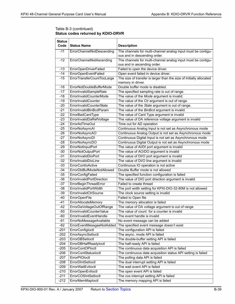
KP
KPXI 48-Channel General Purpose Card User’s Manual Appendix B: KDIO-DRVR Function Reference
-11 ErrorChannelNotDescending The channels for multi-channel analog input must be contigu-ous and in descending order.
-12 ErrorChannelNotAscending The channels for multi-channel analog input must be contigu-ous and in ascending order.
-13 ErrorOpenDriverFailed Failed to open the device driver.-14 ErrorOpenEventFailed Open event failed in device driver.-15 ErrorTransferCountTooLarge The size of transfer is larger than the size of Initially allocated
memory in driver.-16 ErrorNotDoubleBufferMode Double buffer mode is disabled.-17 ErrorInvalidSampleRate The specified sampling rate is out of range.-18 ErrorInvalidCounterMode The value of the Mode argument is invalid.-19 ErrorInvalidCounter The value of the Ctr argument is out of range.-20 ErrorInvalidCounterState The value of the State argument is out of range.-21 ErrorInvalidBinBcdParam The value of the BinBcd argument is invalid.-22 ErrorBadCardType The value of Card Type argument is invalid-23 ErrorInvalidDaRefVoltage The value of DA reference voltage argument is invalid-24 ErrorAdTimeOut Time out for AD operation -25 ErrorNoAsyncAI Continuous Analog Input is not set as Asynchronous mode-26 ErrorNoAsyncAO Continuous Analog Output is not set as Asynchronous mode-27 ErrorNoAsyncDI Continuous Digital Input is not set as Asynchronous mode-28 ErrorNoAsyncDO Continuous Digital Output is not set as Asynchronous mode-29 ErrorNotInputPort The value of AI/DI port argument is invalid-30 ErrorNotOutputPort The value of AO/DO argument is invalid-31 ErrorInvalidDioPort The value of DI/O port argument is invalid-32 ErrorInvalidDioLine The value of DI/O line argument is invalid-33 ErrorContIoActive Continuous IO operation is not active-34 ErrorDblBufModeNotAllowed Double Buffer mode is not allowed-35 ErrorConfigFailed The specified function configuration is failed-36 ErrorInvalidPortDirection The value of DIO port direction argument is invalid -37 ErrorBeginThreadError Failed to create thread -38 ErrorInvalidPortWidth The port width setting for KPXI-DIO-32-80M is not allowed -39 ErrorInvalidCtrSource The clock source setting is invalid -40 ErrorOpenFile Failed to Open file-41 ErrorAllocateMemory The memory allocation is failed-42 ErrorDaVoltageOutOfRange The value of DA voltage argument is out of range-50 ErrorInvalidCounterValue The value of count for a counter is invalid-60 ErrorInvalidEventHandle The event handle is invalid-61 ErrorNoMessageAvailable No event message can be added-62 ErrorEventMessgaeNotAdded The specified event message doesn’t exist-201 ErrorConfigIoctl The configuration API is failed-202 ErrorAsyncSetIoctl The async. mode API is failed-203 ErrorDBSetIoctl The double-buffer setting API is failed-204 ErrorDBHalfReadyIoctl The half-ready API is failed-205 ErrorContOPIoctl The continuous data acquisition API is failed-206 ErrorContStatusIoctl The continuous data acquisition status API setting is failed-207 ErrorPIOIoctl The polling data API is failed-208 ErrorDIntSetIoctl The dual interrupt setting API is failed-209 ErrorWaitEvtIoctl The wait event API is failed-210 ErrorOpenEvtIoctl The open event API is failed-211 ErrorCOSIntSetIoctl The cos interrupt setting API is failed-212 ErrorMemMapIoctl The memory mapping API is failed
Table B-3 (contintued)Status codes returned by KDIO-DRVR
StatusCode Status Name Description
XI-DIO-900-01 Rev. A / January 2007 Return to Section Topics B-39
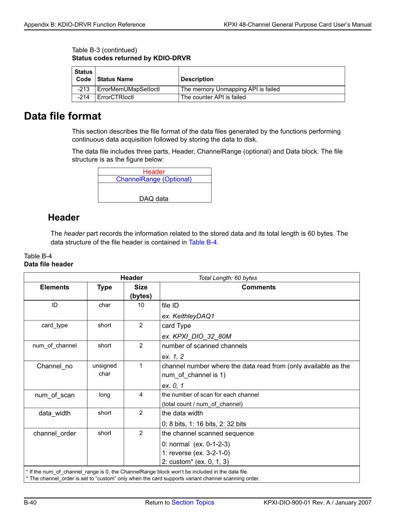
Appendix B: KDIO-DRVR Function Reference KPXI 48-Channel General Purpose Card User’s Manual
Data file formatThis section describes the file format of the data files generated by the functions performing continuous data acquisition followed by storing the data to disk.
The data file includes three parts, Header, ChannelRange (optional) and Data block. The file structure is as the figure below:
HeaderThe header part records the information related to the stored data and its total length is 60 bytes. The data structure of the file header is contained in Table B-4.
-213 ErrorMemUMapSetIoctl The memory Unmapping API is failed-214 ErrorCTRIoctl The counter API is failed
HeaderChannelRange (Optional)
DAQ data
Table B-4 Data file header
Header Total Length: 60 bytesElements Type Size
(bytes)Comments
ID char 10 file IDex. KeithleyDAQ1
card_type short 2 card Typeex. KPXI_DIO_32_80M
num_of_channel short 2 number of scanned channels ex. 1, 2
Channel_no unsigned char
1 channel number where the data read from (only available as the num_of_channel is 1)ex. 0, 1
num_of_scan long 4 the number of scan for each channel(total count / num_of_channel)
data_width short 2 the data width0: 8 bits, 1: 16 bits, 2: 32 bits
channel_order short 2 the channel scanned sequence0: normal (ex. 0-1-2-3)1: reverse (ex. 3-2-1-0)2: custom* (ex. 0, 1, 3)
* If the num_of_channel_range is 0, the ChannelRange block won’t be included in the data file.* The channel_order is set to “custom” only when the card supports variant channel scanning order.
Table B-3 (contintued)Status codes returned by KDIO-DRVR
StatusCode Status Name Description
B-40 Return to Section Topics KPXI-DIO-900-01 Rev. A / January 2007
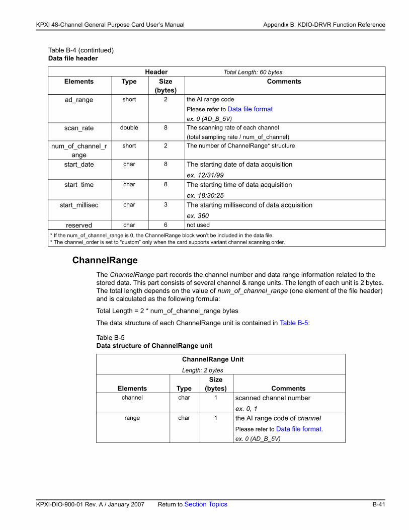
KP
KPXI 48-Channel General Purpose Card User’s Manual Appendix B: KDIO-DRVR Function Reference
ChannelRangeThe ChannelRange part records the channel number and data range information related to the stored data. This part consists of several channel & range units. The length of each unit is 2 bytes. The total length depends on the value of num_of_channel_range (one element of the file header) and is calculated as the following formula:
Total Length = 2 * num_of_channel_range bytes
The data structure of each ChannelRange unit is contained in Table B-5:
ad_range short 2 the AI range codePlease refer to Data file formatex. 0 (AD_B_5V)
scan_rate double 8 The scanning rate of each channel(total sampling rate / num_of_channel)
num_of_channel_range
short 2 The number of ChannelRange* structure
start_date char 8 The starting date of data acquisition ex. 12/31/99
start_time char 8 The starting time of data acquisitionex. 18:30:25
start_millisec char 3 The starting millisecond of data acquisitionex. 360
reserved char 6 not used
Table B-5Data structure of ChannelRange unit
ChannelRange Unit Length: 2 bytes
Elements TypeSize
(bytes) Commentschannel char 1 scanned channel number
ex. 0, 1range char 1 the AI range code of channel
Please refer to Data file format.ex. 0 (AD_B_5V)
Table B-4 (contintued)Data file header
Header Total Length: 60 bytesElements Type Size
(bytes)Comments
* If the num_of_channel_range is 0, the ChannelRange block won’t be included in the data file.* The channel_order is set to “custom” only when the card supports variant channel scanning order.
XI-DIO-900-01 Rev. A / January 2007 Return to Section Topics B-41
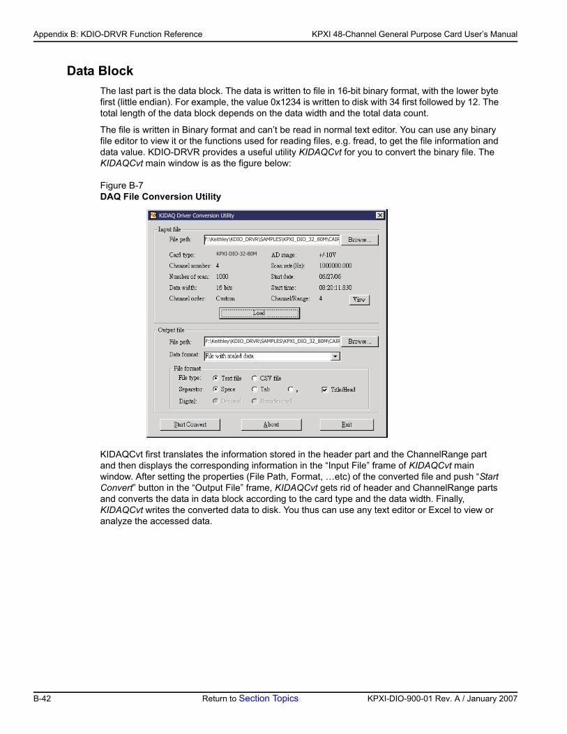
Appendix B: KDIO-DRVR Function Reference KPXI 48-Channel General Purpose Card User’s Manual
Data BlockThe last part is the data block. The data is written to file in 16-bit binary format, with the lower byte first (little endian). For example, the value 0x1234 is written to disk with 34 first followed by 12. The total length of the data block depends on the data width and the total data count.
The file is written in Binary format and can’t be read in normal text editor. You can use any binary file editor to view it or the functions used for reading files, e.g. fread, to get the file information and data value. KDIO-DRVR provides a useful utility KIDAQCvt for you to convert the binary file. The KIDAQCvt main window is as the figure below:
Figure B-7DAQ File Conversion Utility
KIDAQCvt first translates the information stored in the header part and the ChannelRange part and then displays the corresponding information in the “Input File” frame of KIDAQCvt main window. After setting the properties (File Path, Format, …etc) of the converted file and push “Start Convert” button in the “Output File” frame, KIDAQCvt gets rid of header and ChannelRange parts and converts the data in data block according to the card type and the data width. Finally, KIDAQCvt writes the converted data to disk. You thus can use any text editor or Excel to view or analyze the accessed data.
���������������� �!"!�#���$%#����� ��� � ���&��!
�������������
����'(���)��(&�*)��+��*(,������
���������������� �!"!�#���$%#����� ��� � ���&��!
B-42 Return to Section Topics KPXI-DIO-900-01 Rev. A / January 2007
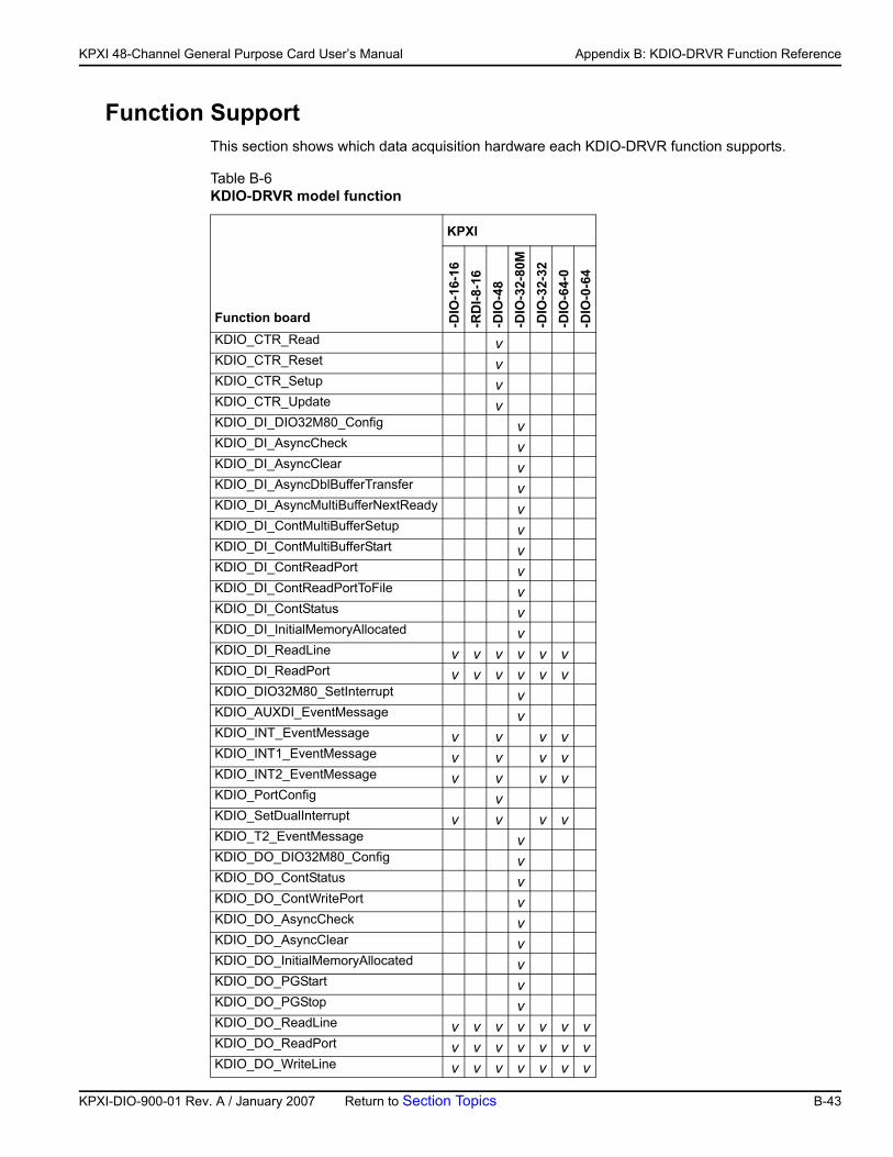
KP
KPXI 48-Channel General Purpose Card User’s Manual Appendix B: KDIO-DRVR Function Reference
Function SupportThis section shows which data acquisition hardware each KDIO-DRVR function supports.
Table B-6 KDIO-DRVR model function
Function board
KPXI
-DIO
-16-
16-R
DI-8
-16
-DIO
-48
-DIO
-32-
80M
-DIO
-32-
32-D
IO-6
4-0
-DIO
-0-6
4
KDIO_CTR_Read vKDIO_CTR_Reset vKDIO_CTR_Setup vKDIO_CTR_Update vKDIO_DI_DIO32M80_Config vKDIO_DI_AsyncCheck vKDIO_DI_AsyncClear vKDIO_DI_AsyncDblBufferTransfer vKDIO_DI_AsyncMultiBufferNextReady vKDIO_DI_ContMultiBufferSetup vKDIO_DI_ContMultiBufferStart vKDIO_DI_ContReadPort vKDIO_DI_ContReadPortToFile vKDIO_DI_ContStatus vKDIO_DI_InitialMemoryAllocated vKDIO_DI_ReadLine v v v v v vKDIO_DI_ReadPort v v v v v vKDIO_DIO32M80_SetInterrupt vKDIO_AUXDI_EventMessage vKDIO_INT_EventMessage v v v vKDIO_INT1_EventMessage v v v vKDIO_INT2_EventMessage v v v vKDIO_PortConfig vKDIO_SetDualInterrupt v v v vKDIO_T2_EventMessage vKDIO_DO_DIO32M80_Config vKDIO_DO_ContStatus vKDIO_DO_ContWritePort vKDIO_DO_AsyncCheck vKDIO_DO_AsyncClear vKDIO_DO_InitialMemoryAllocated vKDIO_DO_PGStart vKDIO_DO_PGStop vKDIO_DO_ReadLine v v v v v v vKDIO_DO_ReadPort v v v v v v vKDIO_DO_WriteLine v v v v v v v
XI-DIO-900-01 Rev. A / January 2007 Return to Section Topics B-43
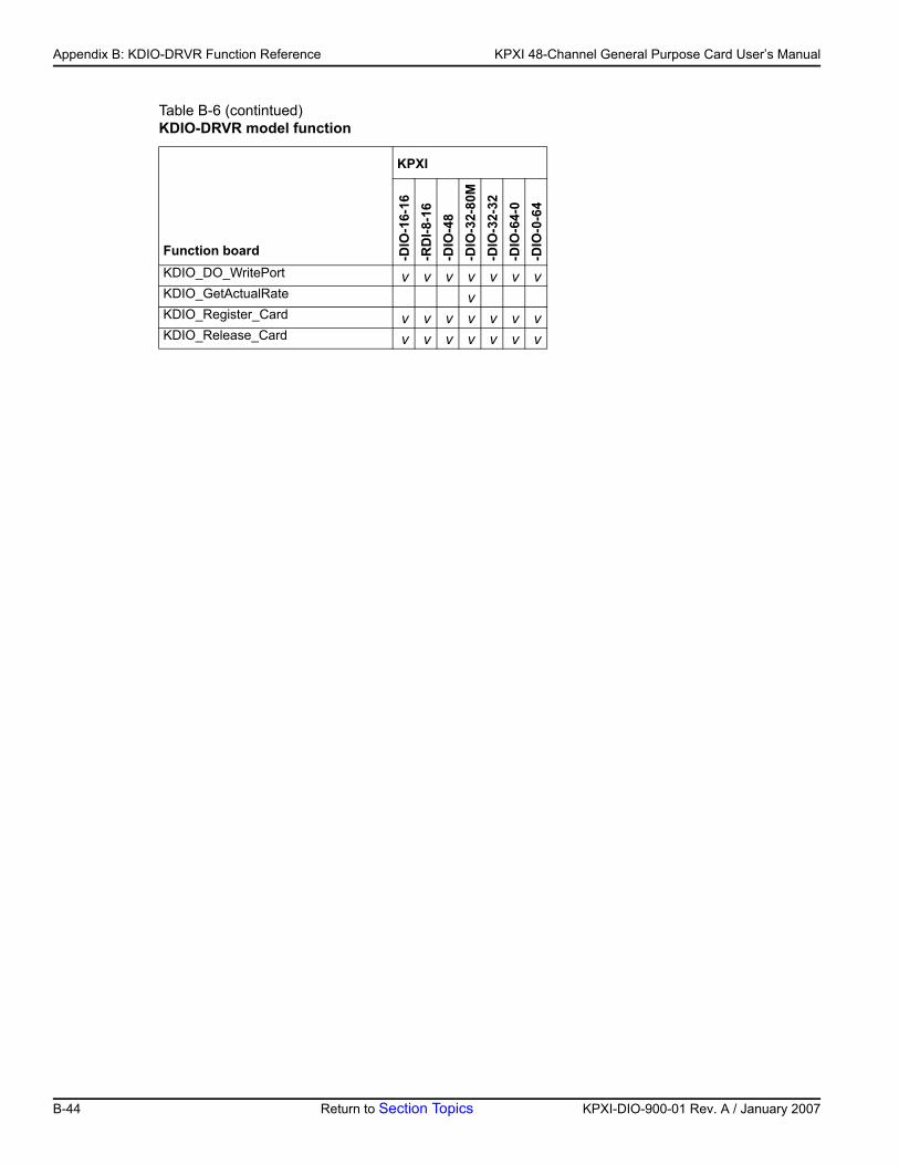
Appendix B: KDIO-DRVR Function Reference KPXI 48-Channel General Purpose Card User’s Manual
KDIO_DO_WritePort v v v v v v vKDIO_GetActualRate vKDIO_Register_Card v v v v v v vKDIO_Release_Card v v v v v v v
Table B-6 (contintued)KDIO-DRVR model function
Function board
KPXI
-DIO
-16-
16-R
DI-8
-16
-DIO
-48
-DIO
-32-
80M
-DIO
-32-
32-D
IO-6
4-0
-DIO
-0-6
4
B-44 Return to Section Topics KPXI-DIO-900-01 Rev. A / January 2007
Appendix C KIDAQ®-LabVIEW Compatible Interface Guide
In this appendix:
Topic Page
Introduction to KIDAQ®-LabVIEW................................................... C-2Overview....................................................................................... C-2Using KIDAQ LabVIEW VIs in LabVIEW...................................... C-2KIDAQ LabVIEW Programming.................................................... C-3
Device Driver Handling..................................................................... C-4Windows XP/2000 Device Driver.................................................. C-4Driver Utility .................................................................................. C-4
KIDAQ Utilities .................................................................................. C-4KIDAQ Registry/Configuration utility............................................. C-4KIDAQ Device Browser ................................................................ C-4
KIDAQ LabVIEW VIs Overview ........................................................ C-5Analog Input VIs ........................................................................... C-6Analog Output VIs ........................................................................ C-6Digital I/O VIs................................................................................ C-7Timer/Counter VIs......................................................................... C-7Calibration and Configuration VIs ................................................. C-8Error Handler VI............................................................................ C-8
Distribution of Applications ............................................................. C-8Windows XP/2000 ........................................................................ C-8
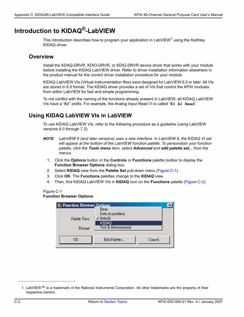
Appendix C: KIDAQ®-LabVIEW Compatible Interface Guide KPXI 48-Channel General Purpose Card User’s Manual
Introduction to KIDAQ®-LabVIEWThis introduction describes how to program your application in LabVIEW1 using the Keithley KIDAQ driver.
OverviewInstall the KDAQ-DRVR, KDIO-DRVR, or KDIG-DRVR device driver that works with your module before installing the KIDAQ LabVIEW driver. Refer to driver installation information elsewhere in the product manual for the correct driver installation procedure for your module.
KIDAQ LabVIEW VIs (Virtual Instrumentation files) were designed for LabVIEW 6.0 or later. All VIs are stored in 6.0 format. The KIDAQ driver provides a set of VIs that control the KPXI modules from within LabVIEW for fast and simple programming.
To not conflict with the naming of the functions already present in LabVIEW, all KIDAQ LabVIEW VIs have a “KI” prefix. For example, the Analog Input Read VI is called “KI AI Read”.
Using KIDAQ LabVIEW VIs in LabVIEWTo use KIDAQ LabVIEW VIs, refer to the following procedure as a guideline (using LabVIEW versions 6.0 through 7.2):
NOTE LabVIEW 8 (and later versions) uses a new interface. In LabVIEW 8, the KIDAQ VI set will appear at the bottom of the LabVIEW function palette. To personalize your function palette, click the Tools menu item, select Advanced and edit palette set... from the menus.
1. Click the Options button in the Controls or Functions palette toolbar to display the Function Browser Options dialog box.
2. Select KIDAQ view from the Palette Set pull-down menu (Figure C-1). 3. Click OK. The Functions palettes change to the KIDAQ view. 4. Then, find KIDAQ LabVIEW VIs in KIDAQ icon on the Functions palette (Figure C-2).
Figure C-1Function Browser Options
1. LabVIEW™ is a trademark of the National Instruments Corporation. All other trademarks are the property of their respective owners.
����'
C-2 Return to Section Topics KPXI-DIO-900-01 Rev. A / January 2007
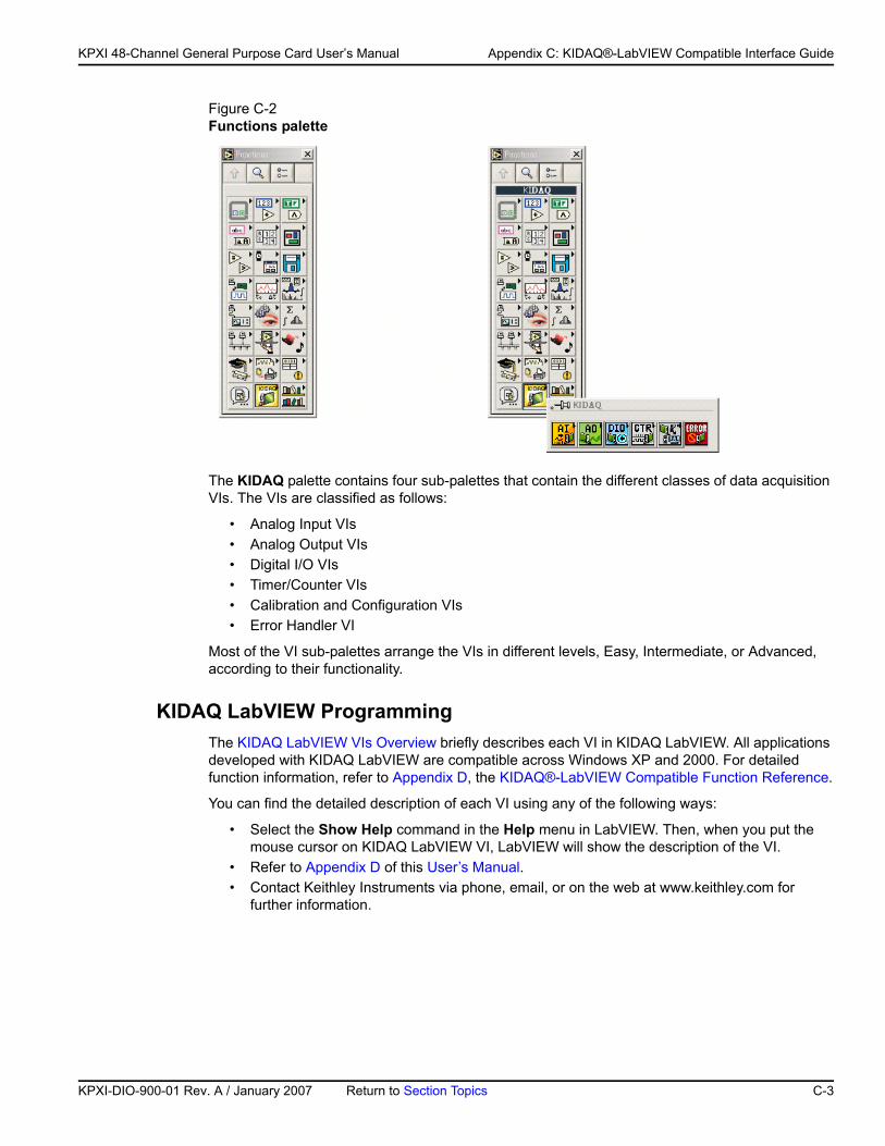
KP
KPXI 48-Channel General Purpose Card User’s Manual Appendix C: KIDAQ®-LabVIEW Compatible Interface Guide
Figure C-2Functions palette
The KIDAQ palette contains four sub-palettes that contain the different classes of data acquisition VIs. The VIs are classified as follows:
• Analog Input VIs• Analog Output VIs• Digital I/O VIs• Timer/Counter VIs• Calibration and Configuration VIs• Error Handler VI
Most of the VI sub-palettes arrange the VIs in different levels, Easy, Intermediate, or Advanced, according to their functionality.
KIDAQ LabVIEW ProgrammingThe KIDAQ LabVIEW VIs Overview briefly describes each VI in KIDAQ LabVIEW. All applications developed with KIDAQ LabVIEW are compatible across Windows XP and 2000. For detailed function information, refer to Appendix D, the KIDAQ®-LabVIEW Compatible Function Reference.
You can find the detailed description of each VI using any of the following ways:
• Select the Show Help command in the Help menu in LabVIEW. Then, when you put the mouse cursor on KIDAQ LabVIEW VI, LabVIEW will show the description of the VI.
• Refer to Appendix D of this User’s Manual.• Contact Keithley Instruments via phone, email, or on the web at www.keithley.com for
further information.
XI-DIO-900-01 Rev. A / January 2007 Return to Section Topics C-3
Appendix C: KIDAQ®-LabVIEW Compatible Interface Guide KPXI 48-Channel General Purpose Card User’s Manual
Device Driver HandlingDevice Driver Handling describes how to configure the KIDAQ PXI cards Windows® XP/2000 device driver.
Windows XP/2000 Device DriverOnce Windows XP/2000® has started, the Plug and Play function of Windows XP/2000® operating system will find the new Keithley PXI cards. If this is the first time to install Keithley PXI cards in your Windows XP/2000® system, you will be informed to install the device driver. Refer to driver installation information elsewhere in the product manual for the correct driver installation procedure for your module.
Driver Utility
NOTE The KDAQ-DRVR, KDIO-DRVR, or KDIG-DRVR device driver should be installed before the KDAQ LabVIEW driver. Refer to driver installation information elsewhere in the product manual for the correct driver installation procedure for your module.
KIDAQ LabVIEW provides a PXI Configuration Utility (configdrv.exe). These utilities are used to set/change the allocated buffer sizes of AI, AO, DI and DO (Analog Input, Analog Output, Digital Input, Digital Output). The allocated buffer sizes of AI, AO, DI, DO represent the sizes of contiguous Initially Allocated memory for continuous analog input, analog output, digital input, digital output respectively. Its unit is page KB, i.e. 1024 bytes. The device driver will try to allocate these sizes of memory at system startup time. If this size of memory is not available, the driver will allocate as much memory as system can provide. The size of initially allocated memory is the maximum memory size that DMA or Interrupt transfer can be performed. It will induce an unexpected result in that DMA or Interrupt transfer performed exceeds the initially allocated size.
KIDAQ UtilitiesThis section, KIDAQ Utilities, describes all utilities included in the KIDAQ software.
KIDAQ Registry/Configuration utilityconfigdrv is used to modify the allocated buffer sizes of AI, AO, DI and DO (Windows® XP/2000). The default installation directory for this utility is C:\Keithley\KIDAQ\Util. It can also be found in the start menu under Programs -> Keithley -> KIDAQ LabVIEW Driver -> Configuration Utility. For detailed information on this utility, refer to device driver guide for you module.
KIDAQ Device BrowserDevice Browser (KPXIConf.exe) displays the currently installed and detected KIDAQ hardware. The default installation directory for this utility is C:\Keithley\KIDAQ\Util. It can also be found in the start menu under Programs -> Keithley -> KIDAQ LabVIEW Driver -> Device Explorer. The KIDAQ device browser main window is shown in Figure C-3:
C-4 Return to Section Topics KPXI-DIO-900-01 Rev. A / January 2007
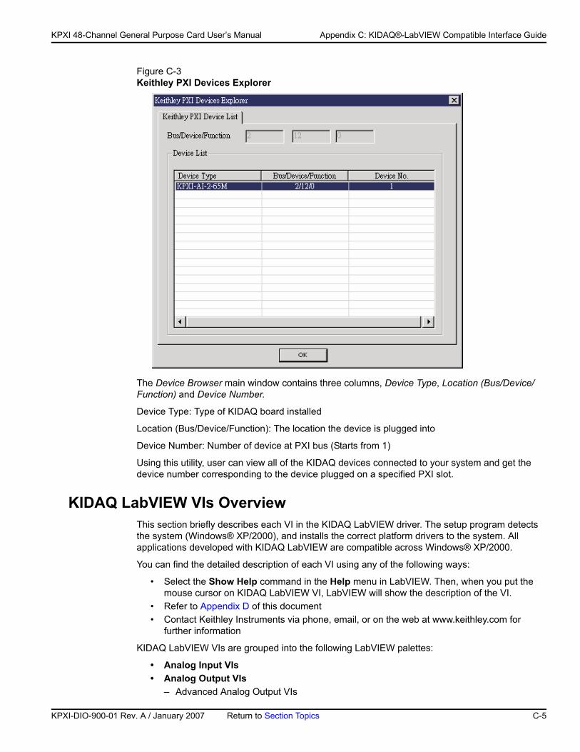
KP
KPXI 48-Channel General Purpose Card User’s Manual Appendix C: KIDAQ®-LabVIEW Compatible Interface Guide
Figure C-3Keithley PXI Devices Explorer
The Device Browser main window contains three columns, Device Type, Location (Bus/Device/Function) and Device Number.
Device Type: Type of KIDAQ board installed
Location (Bus/Device/Function): The location the device is plugged into
Device Number: Number of device at PXI bus (Starts from 1)
Using this utility, user can view all of the KIDAQ devices connected to your system and get the device number corresponding to the device plugged on a specified PXI slot.
KIDAQ LabVIEW VIs OverviewThis section briefly describes each VI in the KIDAQ LabVIEW driver. The setup program detects the system (Windows® XP/2000), and installs the correct platform drivers to the system. All applications developed with KIDAQ LabVIEW are compatible across Windows® XP/2000.
You can find the detailed description of each VI using any of the following ways:
• Select the Show Help command in the Help menu in LabVIEW. Then, when you put the mouse cursor on KIDAQ LabVIEW VI, LabVIEW will show the description of the VI.
• Refer to Appendix D of this document• Contact Keithley Instruments via phone, email, or on the web at www.keithley.com for
further information
KIDAQ LabVIEW VIs are grouped into the following LabVIEW palettes:
• Analog Input VIs• Analog Output VIs
– Advanced Analog Output VIs
XI-DIO-900-01 Rev. A / January 2007 Return to Section Topics C-5
Appendix C: KIDAQ®-LabVIEW Compatible Interface Guide KPXI 48-Channel General Purpose Card User’s Manual
• Digital I/O VIs – Advanced Digital I/O
• Timer/Counter VIs – Intermediate Timer/Counter VIs – Advanced Timer/Counter VIs
• Calibration and Configuration VIs• Error Handler VI
Analog Input VIsKI AI Acquire Waveform: Acquires a specified number of samples at a specified sample rate from a single input channel and returns the acquired data.
KI AI Acquire Waveforms: Acquires data from the specified channels and samples the channels at the specified scan rate.
KI AI Sample Channel: Measures the signal attached to the specified channel and returns the measured data.
KI AI Sample Channels: Performs a single reading from each of the specified channels.
KI AI Clear: The KI AI Clear VI stops an acquisition associated with task ID in.
KI AI Config: Configures an analog input operation for a specified set of channels.
KI AI Read: Reads data from a buffered data acquisition.
KI AI Single Scan: Returns one scan of data directly from the board analog input channels for a non-buffered acquisition.
KI AI Start: Starts a buffered analog input operation.
Analog Output VIsKI AO Generate Waveform: Generates a timed and buffered waveform for the given output channel at the specified update rate.
KI AO Generate Waveforms: Generates timed and buffered waveforms for the given output channels at the specified update rate.
KI AO Update Channel: Writes a specified value to an analog output channel.
KI AO Update Channels: Writes values to each of the specified analog output channels.
KI AO Clear: The KI AO Clear VI stops an analog output generation associated with task ID.
KI AO Config: Configures a buffered analog output operation.
KI AO Start: Starts a buffered analog output operation.
KI AO Wait: waits until the waveform generation of the task completes before returning.
KI AO Write: writes data into the buffer for a buffered analog output operation.
Advanced Analog Output VIsKI AO Trigger and Gate Config: Configures the trigger conditions for analog output operations.
C-6 Return to Section Topics KPXI-DIO-900-01 Rev. A / January 2007
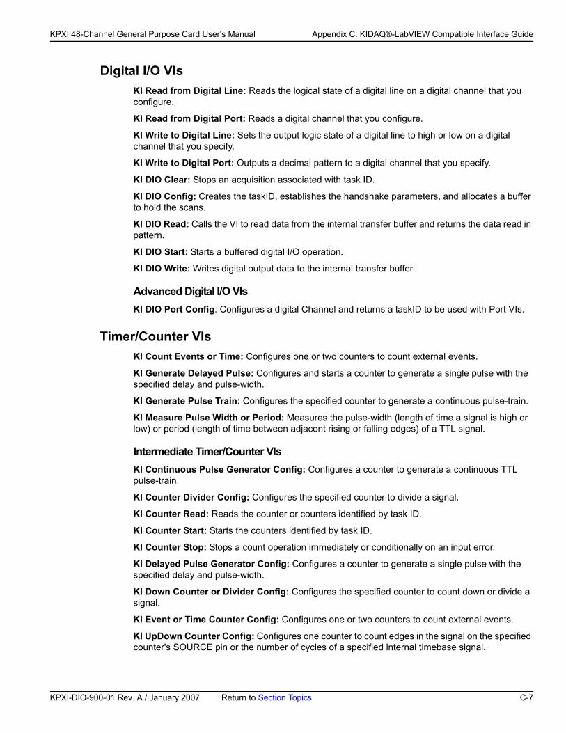
KP
KPXI 48-Channel General Purpose Card User’s Manual Appendix C: KIDAQ®-LabVIEW Compatible Interface Guide
Digital I/O VIsKI Read from Digital Line: Reads the logical state of a digital line on a digital channel that you configure.
KI Read from Digital Port: Reads a digital channel that you configure.
KI Write to Digital Line: Sets the output logic state of a digital line to high or low on a digital channel that you specify.
KI Write to Digital Port: Outputs a decimal pattern to a digital channel that you specify.
KI DIO Clear: Stops an acquisition associated with task ID.
KI DIO Config: Creates the taskID, establishes the handshake parameters, and allocates a buffer to hold the scans.
KI DIO Read: Calls the VI to read data from the internal transfer buffer and returns the data read in pattern.
KI DIO Start: Starts a buffered digital I/O operation.
KI DIO Write: Writes digital output data to the internal transfer buffer.
Advanced Digital I/O VIsKI DIO Port Config: Configures a digital Channel and returns a taskID to be used with Port VIs.
Timer/Counter VIsKI Count Events or Time: Configures one or two counters to count external events.
KI Generate Delayed Pulse: Configures and starts a counter to generate a single pulse with the specified delay and pulse-width.
KI Generate Pulse Train: Configures the specified counter to generate a continuous pulse-train.
KI Measure Pulse Width or Period: Measures the pulse-width (length of time a signal is high or low) or period (length of time between adjacent rising or falling edges) of a TTL signal.
Intermediate Timer/Counter VIsKI Continuous Pulse Generator Config: Configures a counter to generate a continuous TTL pulse-train.
KI Counter Divider Config: Configures the specified counter to divide a signal.
KI Counter Read: Reads the counter or counters identified by task ID.
KI Counter Start: Starts the counters identified by task ID.
KI Counter Stop: Stops a count operation immediately or conditionally on an input error.
KI Delayed Pulse Generator Config: Configures a counter to generate a single pulse with the specified delay and pulse-width.
KI Down Counter or Divider Config: Configures the specified counter to count down or divide a signal.
KI Event or Time Counter Config: Configures one or two counters to count external events.
KI UpDown Counter Config: Configures one counter to count edges in the signal on the specified counter's SOURCE pin or the number of cycles of a specified internal timebase signal.
XI-DIO-900-01 Rev. A / January 2007 Return to Section Topics C-7
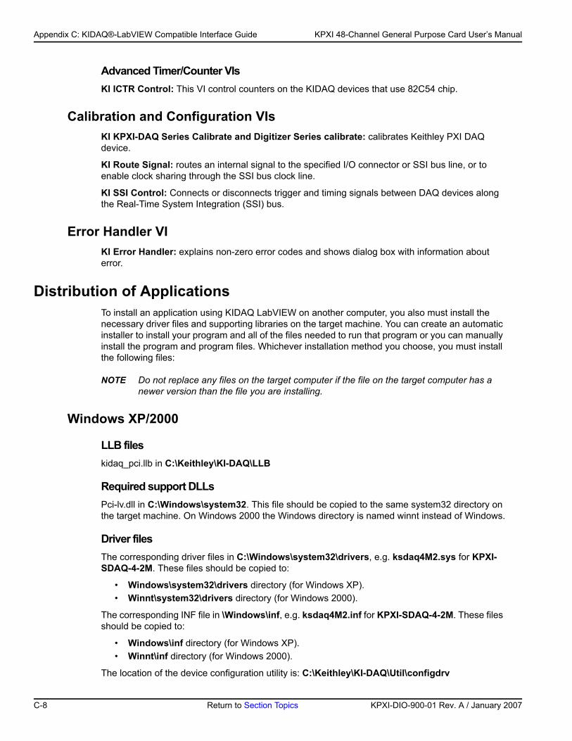
Appendix C: KIDAQ®-LabVIEW Compatible Interface Guide KPXI 48-Channel General Purpose Card User’s Manual
Advanced Timer/Counter VIsKI ICTR Control: This VI control counters on the KIDAQ devices that use 82C54 chip.
Calibration and Configuration VIsKI KPXI-DAQ Series Calibrate and Digitizer Series calibrate: calibrates Keithley PXI DAQ device.
KI Route Signal: routes an internal signal to the specified I/O connector or SSI bus line, or to enable clock sharing through the SSI bus clock line.
KI SSI Control: Connects or disconnects trigger and timing signals between DAQ devices along the Real-Time System Integration (SSI) bus.
Error Handler VIKI Error Handler: explains non-zero error codes and shows dialog box with information about error.
Distribution of ApplicationsTo install an application using KIDAQ LabVIEW on another computer, you also must install the necessary driver files and supporting libraries on the target machine. You can create an automatic installer to install your program and all of the files needed to run that program or you can manually install the program and program files. Whichever installation method you choose, you must install the following files:
NOTE Do not replace any files on the target computer if the file on the target computer has a newer version than the file you are installing.
Windows XP/2000
LLB fileskidaq_pci.llb in C:\Keithley\KI-DAQ\LLB
Required support DLLsPci-lv.dll in C:\Windows\system32. This file should be copied to the same system32 directory on the target machine. On Windows 2000 the Windows directory is named winnt instead of Windows.
Driver filesThe corresponding driver files in C:\Windows\system32\drivers, e.g. ksdaq4M2.sys for KPXI-SDAQ-4-2M. These files should be copied to:
• Windows\system32\drivers directory (for Windows XP).• Winnt\system32\drivers directory (for Windows 2000).
The corresponding INF file in \Windows\inf, e.g. ksdaq4M2.inf for KPXI-SDAQ-4-2M. These files should be copied to:
• Windows\inf directory (for Windows XP).• Winnt\inf directory (for Windows 2000).
The location of the device configuration utility is: C:\Keithley\KI-DAQ\Util\configdrv
C-8 Return to Section Topics KPXI-DIO-900-01 Rev. A / January 2007
Appendix D KIDAQ®-LabVIEW Compatible Function Reference
In this appendix:
Topic Page
Introduction.........................................................................................D-2
Hardware support ..............................................................................D-2KPXI-DIO series: ..............................................................................D-2KPXI-DAQ series: .............................................................................D-2Digitizer series: .................................................................................D-2
Analog input VIs.................................................................................D-3Easy analog input VIs.......................................................................D-3Intermediate analog input VIs...........................................................D-7
Analog output VIs ............................................................................D-21Easy analog output VIs...................................................................D-21Intermediate analog output VIs.......................................................D-24Advanced analog output VIs...........................................................D-32
Digital I/O VIs ....................................................................................D-33Easy Digital I/O VIs.........................................................................D-33Intermediate Digital I/O VIs.............................................................D-37Advanced Digital I/O VIs.................................................................D-45
Counter VIs........................................................................................D-46Easy Counter VIs ...........................................................................D-46Intermediate Counter VIs ...............................................................D-50Advanced Counter VIs ...................................................................D-63
Calibration and Configuration VIs ..............................................D-67Calibration VIs ...............................................................................D-67Other Calibration and Configuration VIs.........................................D-68
Service VIs.........................................................................................D-70
Error Codes ......................................................................................D-71
AI Range Codes ..............................................................................D-73
AI Data Format .................................................................................D-76
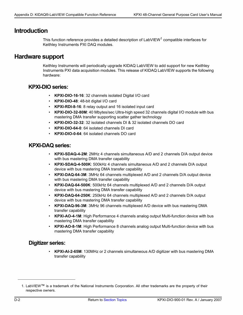
Appendix D: KIDAQ®-LabVIEW Compatible Function Reference KPXI 48-Channel General Purpose Card User’s Manual
IntroductionThis function reference provides a detailed description of LabVIEW1 compatible interfaces for Keithley Instruments PXI DAQ modules.
Hardware supportKeithley Instruments will periodically upgrade KIDAQ LabVIEW to add support for new Keithley Instruments PXI data acquisition modules. This release of KIDAQ LabVIEW supports the following hardware:
KPXI-DIO series:• KPXI-DIO-16-16: 32 channels isolated Digital I/O card• KPXI-DIO-48: 48-bit digital I/O card• KPXI-RDI-8-16: 8 relay output and 16 isolated input card• KPXI-DIO-32-80M: 40 Mbytes/sec Ultra-high speed 32 channels digital I/O module with bus
mastering DMA transfer supporting scatter gather technology• KPXI-DIO-32-32: 32 isolated channels DI & 32 isolated channels DO card • KPXI-DIO-64-0: 64 isolated channels DI card• KPXI-DIO-0-64: 64 isolated channels DO card
KPXI-DAQ series:• KPXI-SDAQ-4-2M: 2MHz 4 channels simultaneous A/D and 2 channels D/A output device
with bus mastering DMA transfer capability• KPXI-SDAQ-4-500K: 500kHz 4 channels simultaneous A/D and 2 channels D/A output
device with bus mastering DMA transfer capability• KPXI-DAQ-64-3M: 3MHz 64 channels multiplexed A/D and 2 channels D/A output device
with bus mastering DMA transfer capability• KPXI-DAQ-64-500K: 500kHz 64 channels multiplexed A/D and 2 channels D/A output
device with bus mastering DMA transfer capability• KPXI-DAQ-64-250K: 250kHz 64 channels multiplexed A/D and 2 channels D/A output
device with bus mastering DMA transfer capability• KPXI-DAQ-96-3M: 3MHz 96 channels multiplexed A/D device with bus mastering DMA
transfer capability• KPXI-AO-4-1M: High Performance 4 channels analog output Multi-function device with bus
mastering DMA transfer capability• KPXI-AO-8-1M: High Performance 8 channels analog output Multi-function device with bus
mastering DMA transfer capability
Digitizer series:• KPXI-AI-2-65M: 130MHz or 2 channels simultaneous A/D digitizer with bus mastering DMA
transfer capability
1. LabVIEW™ is a trademark of the National Instruments Corporation. All other trademarks are the property of their respective owners.
D-2 Return to Section Topics KPXI-DIO-900-01 Rev. A / January 2007
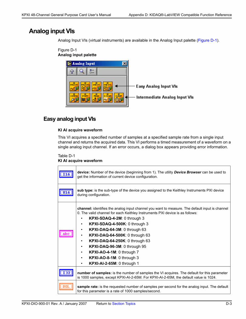
KP
KPXI 48-Channel General Purpose Card User’s Manual Appendix D: KIDAQ®-LabVIEW Compatible Function Reference
Analog input VIsAnalog Input VIs (virtual instruments) are available in the Analog Input palette (Figure D-1).
Figure D-1Analog input palette
Easy analog input VIs
KI AI acquire waveform
This VI acquires a specified number of samples at a specified sample rate from a single input channel and returns the acquired data. This VI performs a timed measurement of a waveform on a single analog input channel. If an error occurs, a dialog box appears providing error information.
Table D-1 KI AI acquire waveform
device: Number of the device (beginning from 1). The utility Device Browser can be used to get the information of current device configuration.
sub type: is the sub-type of the device you assigned to the Keithley Instruments PXI device during configuration.
channel: identifies the analog input channel you want to measure. The default input is channel 0. The valid channel for each Keithley Instruments PXI device is as follows:
• KPXI-SDAQ-4-2M: 0 through 3• KPXI-SDAQ-4-500K: 0 through 3 • KPXI-DAQ-64-3M: 0 through 63 • KPXI-DAQ-64-500K: 0 through 63 • KPXI-DAQ-64-250K: 0 through 63 • KPXI-DAQ-96-3M: 0 through 95 • KPXI-AO-4-1M: 0 through 7• KPXI-AO-8-1M: 0 through 3• KPXI-AI-2-65M: 0 through 1
number of samples: is the number of samples the VI acquires. The default for this parameter is 1000 samples, except KPXI-AI-2-65M. For KPXI-AI-2-65M, the default value is 1024.
sample rate: is the requested number of samples per second for the analog input. The default for this parameter is a rate of 1000 samples/second.
XI-DIO-900-01 Rev. A / January 2007 Return to Section Topics D-3
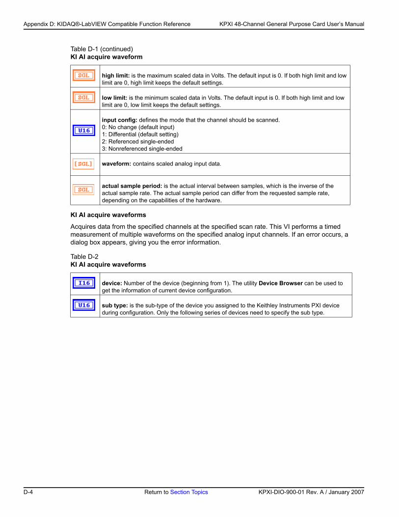
Appendix D: KIDAQ®-LabVIEW Compatible Function Reference KPXI 48-Channel General Purpose Card User’s Manual
KI AI acquire waveforms
Acquires data from the specified channels at the specified scan rate. This VI performs a timed measurement of multiple waveforms on the specified analog input channels. If an error occurs, a dialog box appears, giving you the error information.
high limit: is the maximum scaled data in Volts. The default input is 0. If both high limit and low limit are 0, high limit keeps the default settings.
low limit: is the minimum scaled data in Volts. The default input is 0. If both high limit and low limit are 0, low limit keeps the default settings.
input config: defines the mode that the channel should be scanned. 0: No change (default input)1: Differential (default setting)2: Referenced single-ended3: Nonreferenced single-ended
waveform: contains scaled analog input data.
actual sample period: is the actual interval between samples, which is the inverse of the actual sample rate. The actual sample period can differ from the requested sample rate, depending on the capabilities of the hardware.
Table D-2 KI AI acquire waveforms
device: Number of the device (beginning from 1). The utility Device Browser can be used to get the information of current device configuration.
sub type: is the sub-type of the device you assigned to the Keithley Instruments PXI device during configuration. Only the following series of devices need to specify the sub type.
Table D-1 (continued)KI AI acquire waveform
D-4 Return to Section Topics KPXI-DIO-900-01 Rev. A / January 2007
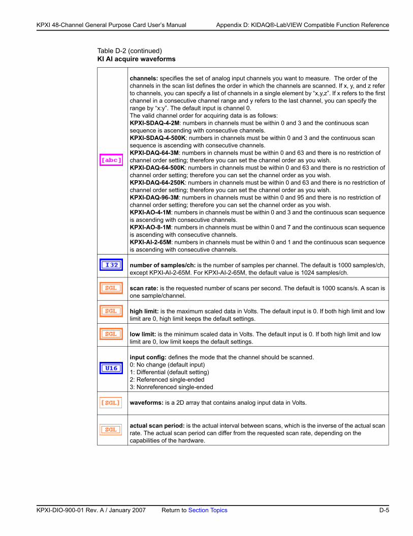
KP
KPXI 48-Channel General Purpose Card User’s Manual Appendix D: KIDAQ®-LabVIEW Compatible Function Reference
channels: specifies the set of analog input channels you want to measure. The order of the channels in the scan list defines the order in which the channels are scanned. If x, y, and z refer to channels, you can specify a list of channels in a single element by “x,y,z”. If x refers to the first channel in a consecutive channel range and y refers to the last channel, you can specify the range by “x:y”. The default input is channel 0.The valid channel order for acquiring data is as follows:KPXI-SDAQ-4-2M: numbers in channels must be within 0 and 3 and the continuous scan sequence is ascending with consecutive channels. KPXI-SDAQ-4-500K: numbers in channels must be within 0 and 3 and the continuous scan sequence is ascending with consecutive channels. KPXI-DAQ-64-3M: numbers in channels must be within 0 and 63 and there is no restriction of channel order setting; therefore you can set the channel order as you wish. KPXI-DAQ-64-500K: numbers in channels must be within 0 and 63 and there is no restriction of channel order setting; therefore you can set the channel order as you wish. KPXI-DAQ-64-250K: numbers in channels must be within 0 and 63 and there is no restriction of channel order setting; therefore you can set the channel order as you wish.KPXI-DAQ-96-3M: numbers in channels must be within 0 and 95 and there is no restriction of channel order setting; therefore you can set the channel order as you wish.KPXI-AO-4-1M: numbers in channels must be within 0 and 3 and the continuous scan sequence is ascending with consecutive channels. KPXI-AO-8-1M: numbers in channels must be within 0 and 7 and the continuous scan sequence is ascending with consecutive channels. KPXI-AI-2-65M: numbers in channels must be within 0 and 1 and the continuous scan sequence is ascending with consecutive channels.
number of samples/ch: is the number of samples per channel. The default is 1000 samples/ch, except KPXI-AI-2-65M. For KPXI-AI-2-65M, the default value is 1024 samples/ch.
scan rate: is the requested number of scans per second. The default is 1000 scans/s. A scan is one sample/channel.
high limit: is the maximum scaled data in Volts. The default input is 0. If both high limit and low limit are 0, high limit keeps the default settings.
low limit: is the minimum scaled data in Volts. The default input is 0. If both high limit and low limit are 0, low limit keeps the default settings.
input config: defines the mode that the channel should be scanned. 0: No change (default input)1: Differential (default setting)2: Referenced single-ended3: Nonreferenced single-ended
waveforms: is a 2D array that contains analog input data in Volts.
actual scan period: is the actual interval between scans, which is the inverse of the actual scan rate. The actual scan period can differ from the requested scan rate, depending on the capabilities of the hardware.
Table D-2 (continued)KI AI acquire waveforms
XI-DIO-900-01 Rev. A / January 2007 Return to Section Topics D-5
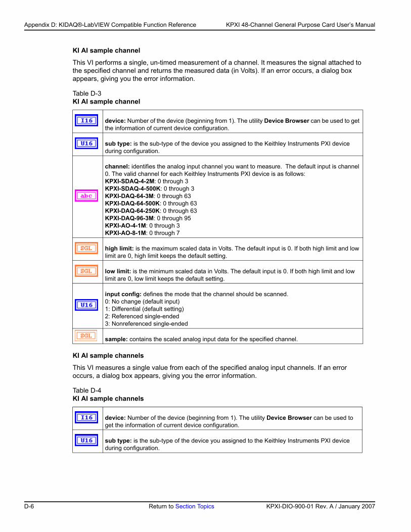
Appendix D: KIDAQ®-LabVIEW Compatible Function Reference KPXI 48-Channel General Purpose Card User’s Manual
KI AI sample channel
This VI performs a single, un-timed measurement of a channel. It measures the signal attached to the specified channel and returns the measured data (in Volts). If an error occurs, a dialog box appears, giving you the error information.
KI AI sample channels
This VI measures a single value from each of the specified analog input channels. If an error occurs, a dialog box appears, giving you the error information.
Table D-3 KI AI sample channel
device: Number of the device (beginning from 1). The utility Device Browser can be used to get the information of current device configuration.
sub type: is the sub-type of the device you assigned to the Keithley Instruments PXI device during configuration.
channel: identifies the analog input channel you want to measure. The default input is channel 0. The valid channel for each Keithley Instruments PXI device is as follows:KPXI-SDAQ-4-2M: 0 through 3KPXI-SDAQ-4-500K: 0 through 3 KPXI-DAQ-64-3M: 0 through 63 KPXI-DAQ-64-500K: 0 through 63 KPXI-DAQ-64-250K: 0 through 63 KPXI-DAQ-96-3M: 0 through 95 KPXI-AO-4-1M: 0 through 3KPXI-AO-8-1M: 0 through 7
high limit: is the maximum scaled data in Volts. The default input is 0. If both high limit and low limit are 0, high limit keeps the default setting.
low limit: is the minimum scaled data in Volts. The default input is 0. If both high limit and low limit are 0, low limit keeps the default setting.
input config: defines the mode that the channel should be scanned. 0: No change (default input)1: Differential (default setting)2: Referenced single-ended3: Nonreferenced single-ended
sample: contains the scaled analog input data for the specified channel.
Table D-4 KI AI sample channels
device: Number of the device (beginning from 1). The utility Device Browser can be used to get the information of current device configuration.
sub type: is the sub-type of the device you assigned to the Keithley Instruments PXI device during configuration.
D-6 Return to Section Topics KPXI-DIO-900-01 Rev. A / January 2007
KP
KPXI 48-Channel General Purpose Card User’s Manual Appendix D: KIDAQ®-LabVIEW Compatible Function Reference
Intermediate analog input VIs
KI AI clear
This VI stops an acquisition operation. Before beginning a new acquisition, you must call the KI AI Config VI.
channels: specifies the set of analog input channels you want to measure. The order of the channels in the scan list defines the order in which the channels are scanned. If x, y, and z refer to channels, you can specify a list of channels in a single element by “x,y,z”. If x refers to the first channel in a consecutive channel range and y refers to the last channel, you can specify the range by “x:y”. The default input is channel 0.The valid channel order for acquiring data is as follows:KPXI-SDAQ-4-2M: numbers in channels must be within 0 and 3 and the continuous scan sequence is ascending with consecutive channels. KPXI-SDAQ-4-500K: numbers in channels must be within 0 and 3 and the continuous scan sequence is ascending with consecutive channels. KPXI-DAQ-64-3M: numbers in channels must be within 0 and 63 and there is no restriction of channel order setting; therefore you can set the channel order as you wish. KPXI-DAQ-64-500K: numbers in channels must be within 0 and 63 and there is no restriction of channel order setting; therefore you can set the channel order as you wish. KPXI-DAQ-64-250K: numbers in channels must be within 0 and 63 and there is no restriction of channel order setting; therefore you can set the channel order as you wish.KPXI-DAQ-96-3M: numbers in channels must be within 0 and 95 and there is no restriction of channel order setting; therefore you can set the channel order as you wish.KPXI-AO-4-1M: numbers in channels must be within 0 and 3 and the continuous scan sequence is ascending with consecutive channels. KPXI-AO-8-1M: numbers in channels must be within 0 and 7 and the continuous scan sequence is ascending with consecutive channels.
high limit: is the maximum scaled data in Volts. The default input is 0. If both high limit and low limit are 0, high limit keeps the default setting.
low limit: is the minimum scaled data in Volts. The default input is 0. If both high limit and low limit are 0, low limit keeps the default setting.
input config: defines the mode that the channel should be scanned. 0: No change (default input)1: Differential (default setting)2: Referenced single-ended3. Nonreferenced single-ended
sample: is a 1D array that contains scaled analog input data.
Table D-5 KI AI clear
taskID in: identifies the group and the I/O operation.
error in (no error): describes error conditions occurring before the VI executes. If an error has already occurred, the VI returns the value of the error in cluster in error out.
Table D-4 (continued)KI AI sample channels
XI-DIO-900-01 Rev. A / January 2007 Return to Section Topics D-7
Appendix D: KIDAQ®-LabVIEW Compatible Function Reference KPXI 48-Channel General Purpose Card User’s Manual
status: is TRUE if an error occurred. If status is TRUE, the VI does not perform any operations.
code: is the error code number identifying an error. A value of 0 means no error, a negative value means a fatal error, and a positive value is a warning. Refer to Table D-52 for a code description.
source: identifies where an error occurred. The source string is usually the name of the VI that produced the error.
taskID out: has the same value as taskID in.
error out: contains error information. If the error in cluster indicated an error, the error out cluster contains the same information. Otherwise, error out describes the error status of this VI.
status: is TRUE if an error occurred. If status is TRUE, the VI does not perform any operations.
code: is the error code number identifying an error. A value of 0 means no error, a negative value means a fatal error, and a positive value is a warning. Refer to Table D-52 for a code description.
source: identifies where an error occurred. The source string is usually the name of the VI that produced the error.
Table D-5 (continued)KI AI clear
D-8 Return to Section Topics KPXI-DIO-900-01 Rev. A / January 2007
KP
KPXI 48-Channel General Purpose Card User’s Manual Appendix D: KIDAQ®-LabVIEW Compatible Function Reference
KI AI config
Configures a buffered analog input operation, including configuring the hardware and allocating a buffer.
Table D-6 KI AI config
interchannel delay: For devices with both scan and channel clocks (KPXI-DAQ series devices), you can use interchannel delay to specify the waiting time between sampling channels within a scan. Select a default interchannel delay automatically, giving the hardware time to settle between channels. The default value for interchannel delay is -1.0, which tells the AI Config VI to use the channel clock rate LabVIEW selects.
sub type: is the sub-type of the device you assigned to the Keithley Instruments PXI device during configuration.
measurement mode structure: This input is not used by Keithley Instruments PXI devices and is ignored.
measurement mode: is not used
reserved: is not used
coupling & input config: is an array of clusters. Each array element contains the configuration for the channel or channels specified by the corresponding element of the channels array. KIDAQ LabVIEW uses only input config. The default for the coupling & input config array is an empty array, which means the parameters keep their default settings.
coupling: This input is not used by Keithley Instruments PXI devices and is ignored.
input config: defines the mode that the channel should be scanned. 0: No change (default input)1: Differential (default setting)2: Referenced single-ended3: Nonreferenced single-ended
input limits: is an array of clusters. Each array element contains the expected signal limits for the channels specified by the corresponding element of channels. If there are fewer elements in this array than in channels, the VI uses the last array element for the rest of the channels. The default for the input limits array is an empty array, which means the input limits keep their default settings.
high limit: is the maximum scaled data in Volts. The default input is 0.
low limit: is the minimum scaled data in Volts. The default input is 0.
device: Number of the device at PXI-bus (beginning from 1). The utility Device Browser can be used to get the information of current device configuration.
XI-DIO-900-01 Rev. A / January 2007 Return to Section Topics D-9
Appendix D: KIDAQ®-LabVIEW Compatible Function Reference KPXI 48-Channel General Purpose Card User’s Manual
channels: specifies the set of analog input channels. The order of the channels in the scan list defines the order in which the channels are scanned. channels is an array of strings. You can use one channel entry per element or specify the entire scan list in a single element, or use any combination of these two methods. If x, y, and z refer to channels, you can specify a list of channels in a single element by “x,y,z”. If x refers to the first channel in a consecutive channel range and y refers to the last channel, you can specify the range by “x:y”.The valid channel order for acquiring data is as follows:KPXI-SDAQ-4-2M: numbers in channels must be within 0 and 3 and the continuous scan sequence is ascending with consecutive channels. KPXI-SDAQ-4-500K: numbers in channels must be within 0 and 3 and the continuous scan sequence is ascending with consecutive channels. KPXI-DAQ-64-3M: numbers in channels must be within 0 and 63 and there is no restriction of channel order setting; therefore you can set the channel order as you wish. KPXI-DAQ-64-500K: numbers in channels must be within 0 and 63 and there is no restriction of channel order setting; therefore you can set the channel order as you wish. KPXI-DAQ-64-250K: numbers in channels must be within 0 and 63 and there is no restriction of channel order setting; therefore you can set the channel order as you wish.KPXI-DAQ-96-3M: numbers in channels must be within 0 and 95 and there is no restriction of channel order setting; therefore you can set the channel order as you wish.KPXI-AO-4-1M: numbers in channels must be within 0 and 7 and the continuous scan sequence is ascending with consecutive channels. KPXI-AO-8-1M: numbers in channels must be within 0 and 3 and the continuous scan sequence is ascending with consecutive channels. KPXI-AI-2-65M: numbers in channels must be within 0 and 1 and the continuous scan sequence is ascending with consecutive channels.
buffer size: is the number of scans you want the buffer to hold. The default for this parameter is 1000 scans, except KPXI-AI-2-65M. For KPXI-AI-2-65M, the default value is 1024 scans.
group: is the number, from 0 to 15, that you assign to the specified set of channels. The default input and setting for group is 0. If you only have one acquisition for this device, leave this input unwired and use group 0.
error in (no error): describes error conditions occurring before the VI executes. If an error has already occurred, the VI returns the value of the error in cluster in error out.
status: is TRUE if an error occurred. If status is TRUE, the VI does not perform any operations.
code: is the error code number identifying an error. A value of 0 means no error, a negative value means a fatal error, and a positive value is a warning. Refer to Table D-52 for a code description.
Table D-6 (continued)KI AI config
D-10 Return to Section Topics KPXI-DIO-900-01 Rev. A / January 2007
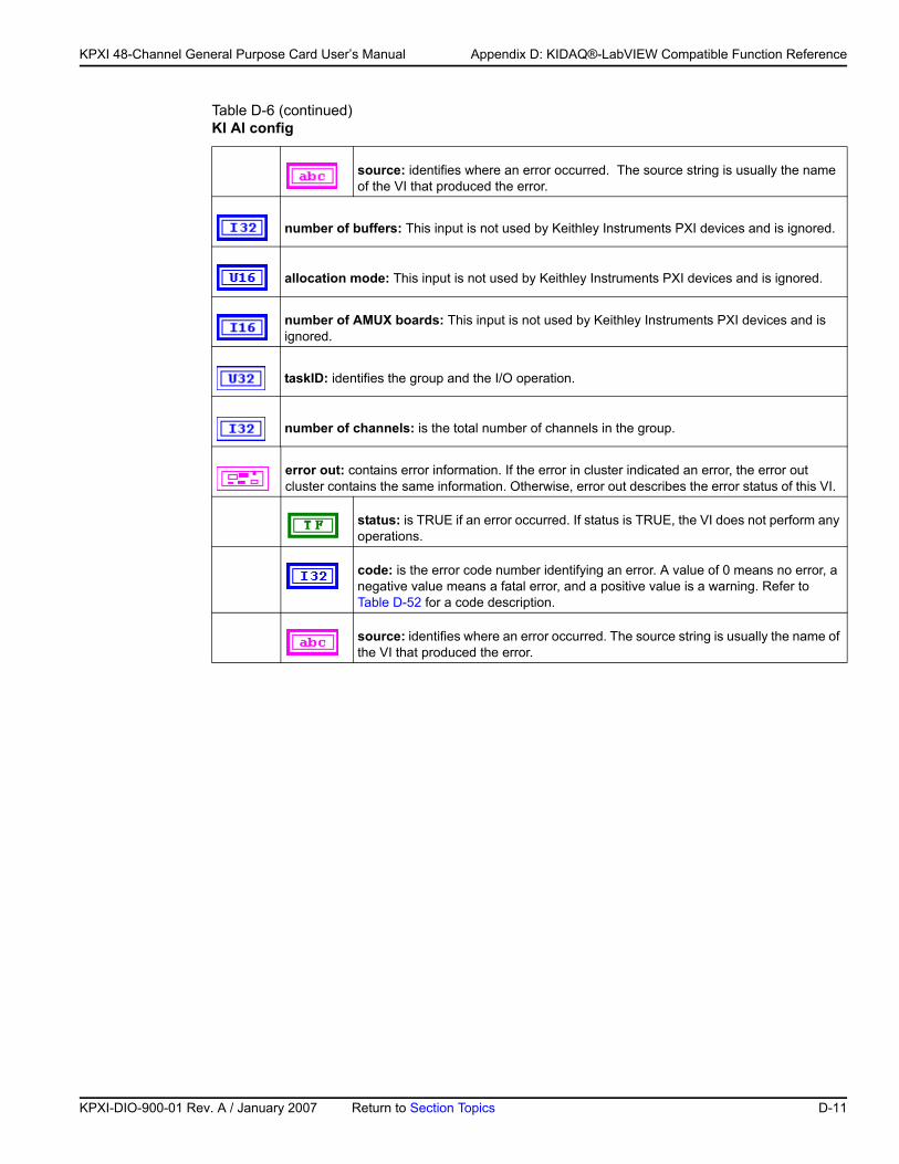
KP
KPXI 48-Channel General Purpose Card User’s Manual Appendix D: KIDAQ®-LabVIEW Compatible Function Reference
source: identifies where an error occurred. The source string is usually the name of the VI that produced the error.
number of buffers: This input is not used by Keithley Instruments PXI devices and is ignored.
allocation mode: This input is not used by Keithley Instruments PXI devices and is ignored.
number of AMUX boards: This input is not used by Keithley Instruments PXI devices and is ignored.
taskID: identifies the group and the I/O operation.
number of channels: is the total number of channels in the group.
error out: contains error information. If the error in cluster indicated an error, the error out cluster contains the same information. Otherwise, error out describes the error status of this VI.
status: is TRUE if an error occurred. If status is TRUE, the VI does not perform any operations.
code: is the error code number identifying an error. A value of 0 means no error, a negative value means a fatal error, and a positive value is a warning. Refer to Table D-52 for a code description.
source: identifies where an error occurred. The source string is usually the name of the VI that produced the error.
Table D-6 (continued)KI AI config
XI-DIO-900-01 Rev. A / January 2007 Return to Section Topics D-11
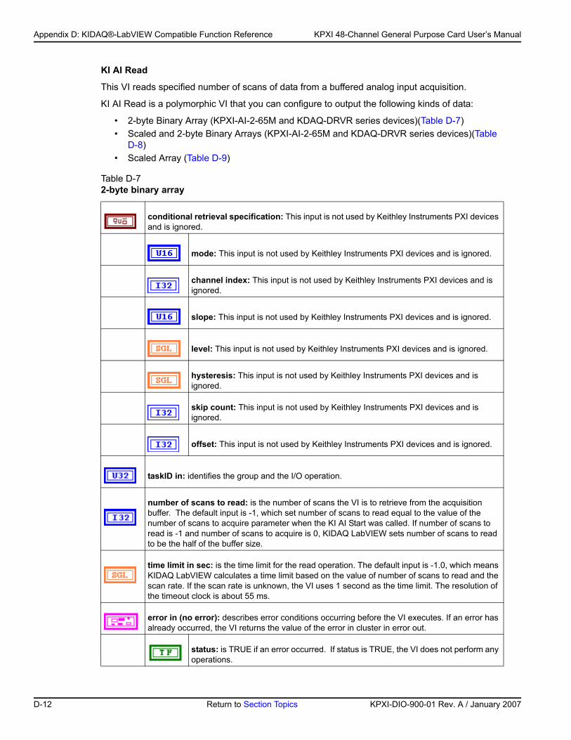
Appendix D: KIDAQ®-LabVIEW Compatible Function Reference KPXI 48-Channel General Purpose Card User’s Manual
KI AI Read
This VI reads specified number of scans of data from a buffered analog input acquisition.
KI AI Read is a polymorphic VI that you can configure to output the following kinds of data:
• 2-byte Binary Array (KPXI-AI-2-65M and KDAQ-DRVR series devices)(Table D-7)• Scaled and 2-byte Binary Arrays (KPXI-AI-2-65M and KDAQ-DRVR series devices)(Table
D-8)• Scaled Array (Table D-9)
Table D-7 2-byte binary array
conditional retrieval specification: This input is not used by Keithley Instruments PXI devices and is ignored.
mode: This input is not used by Keithley Instruments PXI devices and is ignored.
channel index: This input is not used by Keithley Instruments PXI devices and is ignored.
slope: This input is not used by Keithley Instruments PXI devices and is ignored.
level: This input is not used by Keithley Instruments PXI devices and is ignored.
hysteresis: This input is not used by Keithley Instruments PXI devices and is ignored.
skip count: This input is not used by Keithley Instruments PXI devices and is ignored.
offset: This input is not used by Keithley Instruments PXI devices and is ignored.
taskID in: identifies the group and the I/O operation.
number of scans to read: is the number of scans the VI is to retrieve from the acquisition buffer. The default input is -1, which set number of scans to read equal to the value of the number of scans to acquire parameter when the KI AI Start was called. If number of scans to read is -1 and number of scans to acquire is 0, KIDAQ LabVIEW sets number of scans to read to be the half of the buffer size.
time limit in sec: is the time limit for the read operation. The default input is -1.0, which means KIDAQ LabVIEW calculates a time limit based on the value of number of scans to read and the scan rate. If the scan rate is unknown, the VI uses 1 second as the time limit. The resolution of the timeout clock is about 55 ms.
error in (no error): describes error conditions occurring before the VI executes. If an error has already occurred, the VI returns the value of the error in cluster in error out.
status: is TRUE if an error occurred. If status is TRUE, the VI does not perform any operations.
D-12 Return to Section Topics KPXI-DIO-900-01 Rev. A / January 2007
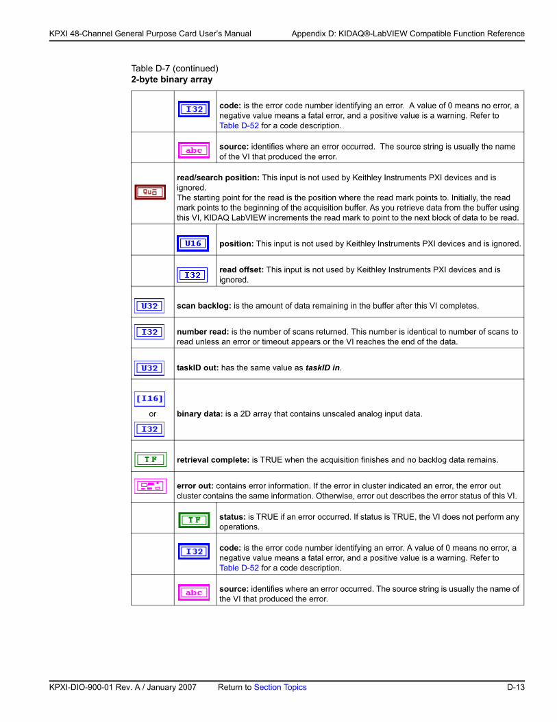
KP
KPXI 48-Channel General Purpose Card User’s Manual Appendix D: KIDAQ®-LabVIEW Compatible Function Reference
code: is the error code number identifying an error. A value of 0 means no error, a negative value means a fatal error, and a positive value is a warning. Refer to Table D-52 for a code description.
source: identifies where an error occurred. The source string is usually the name of the VI that produced the error.
read/search position: This input is not used by Keithley Instruments PXI devices and is ignored. The starting point for the read is the position where the read mark points to. Initially, the read mark points to the beginning of the acquisition buffer. As you retrieve data from the buffer using this VI, KIDAQ LabVIEW increments the read mark to point to the next block of data to be read.
position: This input is not used by Keithley Instruments PXI devices and is ignored.
read offset: This input is not used by Keithley Instruments PXI devices and is ignored.
scan backlog: is the amount of data remaining in the buffer after this VI completes.
number read: is the number of scans returned. This number is identical to number of scans to read unless an error or timeout appears or the VI reaches the end of the data.
taskID out: has the same value as taskID in.
or binary data: is a 2D array that contains unscaled analog input data.
retrieval complete: is TRUE when the acquisition finishes and no backlog data remains.
error out: contains error information. If the error in cluster indicated an error, the error out cluster contains the same information. Otherwise, error out describes the error status of this VI.
status: is TRUE if an error occurred. If status is TRUE, the VI does not perform any operations.
code: is the error code number identifying an error. A value of 0 means no error, a negative value means a fatal error, and a positive value is a warning. Refer to Table D-52 for a code description.
source: identifies where an error occurred. The source string is usually the name of the VI that produced the error.
Table D-7 (continued)2-byte binary array
XI-DIO-900-01 Rev. A / January 2007 Return to Section Topics D-13
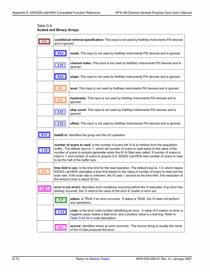
Appendix D: KIDAQ®-LabVIEW Compatible Function Reference KPXI 48-Channel General Purpose Card User’s Manual
Table D-8 Scaled and Binary Arrays
conditional retrieval specification: This input is not used by Keithley Instruments PXI devices and is ignored.
mode: This input is not used by Keithley Instruments PXI devices and is ignored.
channel index: This input is not used by Keithley Instruments PXI devices and is ignored.
slope: This input is not used by Keithley Instruments PXI devices and is ignored.
level: This input is not used by Keithley Instruments PXI devices and is ignored.
hysteresis: This input is not used by Keithley Instruments PXI devices and is ignored.
skip count: This input is not used by Keithley Instruments PXI devices and is ignored.
offset: This input is not used by Keithley Instruments PXI devices and is ignored.
taskID in: Identifies the group and the I/O operation.
number of scans to read: is the number of scans the VI is to retrieve from the acquisition buffer. The default input is -1, which set number of scans to read equal to the value of the number of scans to acquire parameter when the KI AI Start was called. If number of scans to read is -1 and number of scans to acquire is 0, KIDAQ LabVIEW sets number of scans to read to be the half of the buffer size.
time limit in sec: is the time limit for the read operation. The default input is -1.0, which means KIDAQ LabVIEW calculates a time limit based on the value of number of scans to read and the scan rate. If the scan rate is unknown, the VI uses 1 second as the time limit. The resolution of the timeout clock is about 55 ms.
error in (no error): describes error conditions occurring before the VI executes. If an error has already occurred, the VI returns the value of the error in cluster in error out.
status: is TRUE if an error occurred. If status is TRUE, the VI does not perform any operations.
code: is the error code number identifying an error. A value of 0 means no error, a negative value means a fatal error, and a positive value is a warning. Refer to Table D-52 for a code description.
source: Identifies where an error occurred. The source string is usually the name of the VI that produced the error.
D-14 Return to Section Topics KPXI-DIO-900-01 Rev. A / January 2007
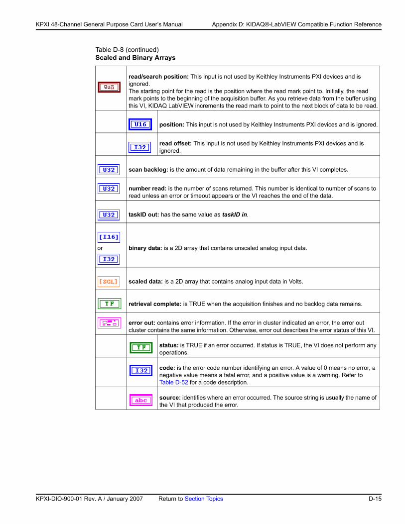
KP
KPXI 48-Channel General Purpose Card User’s Manual Appendix D: KIDAQ®-LabVIEW Compatible Function Reference
read/search position: This input is not used by Keithley Instruments PXI devices and is ignored. The starting point for the read is the position where the read mark point to. Initially, the read mark points to the beginning of the acquisition buffer. As you retrieve data from the buffer using this VI, KIDAQ LabVIEW increments the read mark to point to the next block of data to be read.
position: This input is not used by Keithley Instruments PXI devices and is ignored.
read offset: This input is not used by Keithley Instruments PXI devices and is ignored.
scan backlog: is the amount of data remaining in the buffer after this VI completes.
number read: is the number of scans returned. This number is identical to number of scans to read unless an error or timeout appears or the VI reaches the end of the data.
taskID out: has the same value as taskID in.
or binary data: is a 2D array that contains unscaled analog input data.
scaled data: is a 2D array that contains analog input data in Volts.
retrieval complete: is TRUE when the acquisition finishes and no backlog data remains.
error out: contains error information. If the error in cluster indicated an error, the error out cluster contains the same information. Otherwise, error out describes the error status of this VI.
status: is TRUE if an error occurred. If status is TRUE, the VI does not perform any operations.
code: is the error code number identifying an error. A value of 0 means no error, a negative value means a fatal error, and a positive value is a warning. Refer to Table D-52 for a code description.
source: identifies where an error occurred. The source string is usually the name of the VI that produced the error.
Table D-8 (continued)Scaled and Binary Arrays
XI-DIO-900-01 Rev. A / January 2007 Return to Section Topics D-15
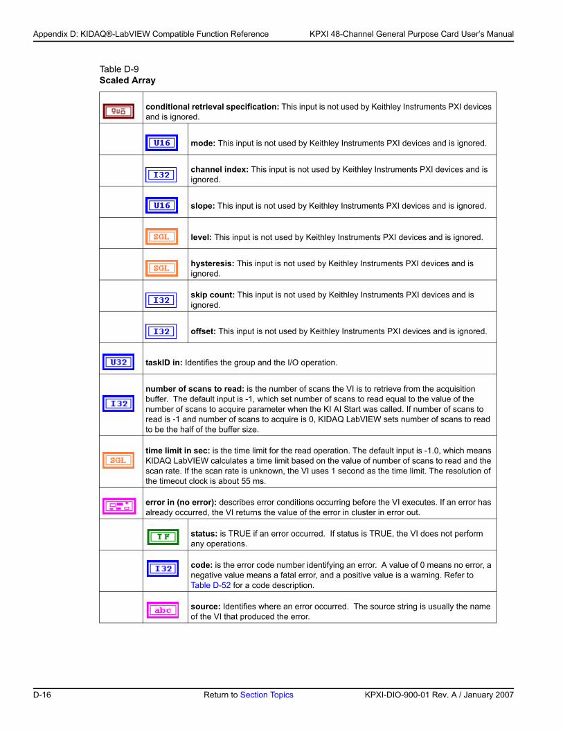
Appendix D: KIDAQ®-LabVIEW Compatible Function Reference KPXI 48-Channel General Purpose Card User’s Manual
Table D-9 Scaled Array
conditional retrieval specification: This input is not used by Keithley Instruments PXI devices and is ignored.
mode: This input is not used by Keithley Instruments PXI devices and is ignored.
channel index: This input is not used by Keithley Instruments PXI devices and is ignored.
slope: This input is not used by Keithley Instruments PXI devices and is ignored.
level: This input is not used by Keithley Instruments PXI devices and is ignored.
hysteresis: This input is not used by Keithley Instruments PXI devices and is ignored.
skip count: This input is not used by Keithley Instruments PXI devices and is ignored.
offset: This input is not used by Keithley Instruments PXI devices and is ignored.
taskID in: Identifies the group and the I/O operation.
number of scans to read: is the number of scans the VI is to retrieve from the acquisition buffer. The default input is -1, which set number of scans to read equal to the value of the number of scans to acquire parameter when the KI AI Start was called. If number of scans to read is -1 and number of scans to acquire is 0, KIDAQ LabVIEW sets number of scans to read to be the half of the buffer size.
time limit in sec: is the time limit for the read operation. The default input is -1.0, which means KIDAQ LabVIEW calculates a time limit based on the value of number of scans to read and the scan rate. If the scan rate is unknown, the VI uses 1 second as the time limit. The resolution of the timeout clock is about 55 ms.
error in (no error): describes error conditions occurring before the VI executes. If an error has already occurred, the VI returns the value of the error in cluster in error out.
status: is TRUE if an error occurred. If status is TRUE, the VI does not perform any operations.
code: is the error code number identifying an error. A value of 0 means no error, a negative value means a fatal error, and a positive value is a warning. Refer to Table D-52 for a code description.
source: Identifies where an error occurred. The source string is usually the name of the VI that produced the error.
D-16 Return to Section Topics KPXI-DIO-900-01 Rev. A / January 2007
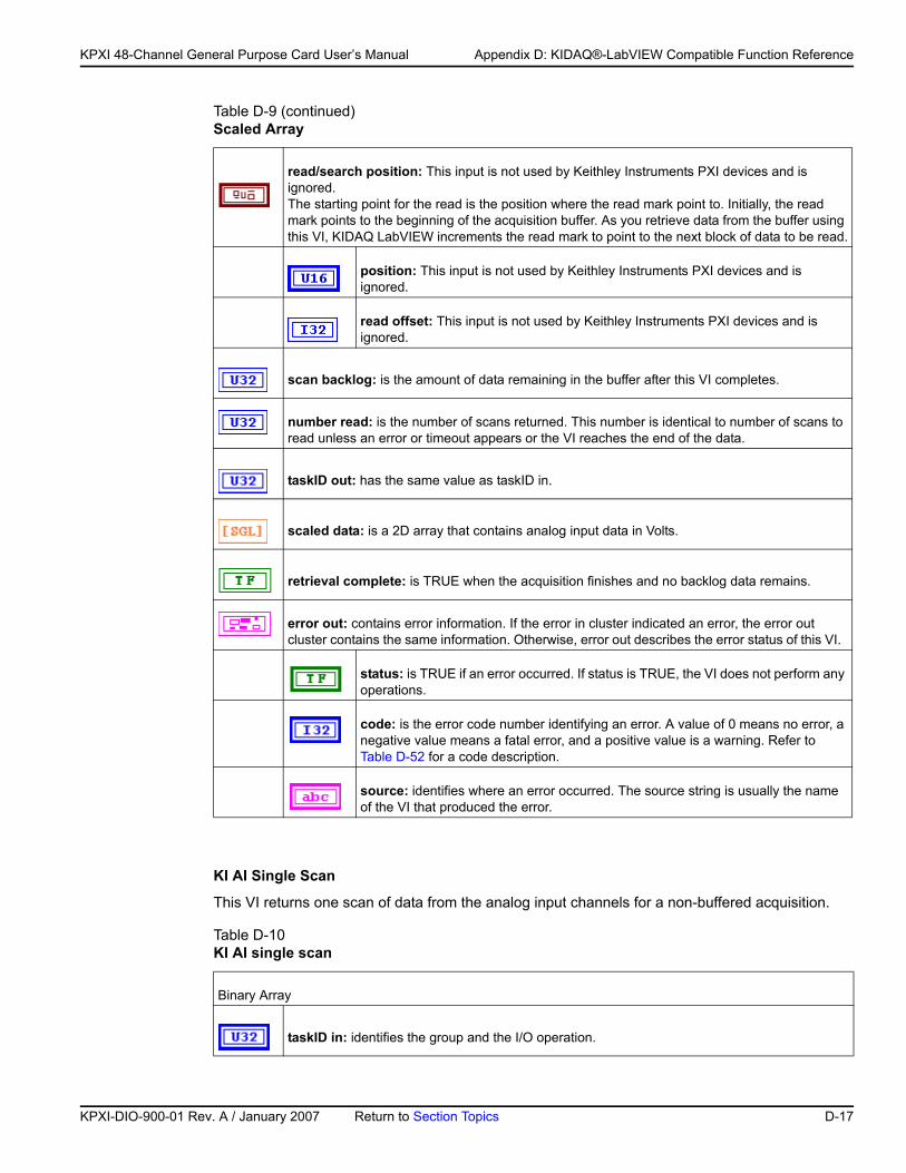
KP
KPXI 48-Channel General Purpose Card User’s Manual Appendix D: KIDAQ®-LabVIEW Compatible Function Reference
KI AI Single Scan
This VI returns one scan of data from the analog input channels for a non-buffered acquisition.
read/search position: This input is not used by Keithley Instruments PXI devices and is ignored. The starting point for the read is the position where the read mark point to. Initially, the read mark points to the beginning of the acquisition buffer. As you retrieve data from the buffer using this VI, KIDAQ LabVIEW increments the read mark to point to the next block of data to be read.
position: This input is not used by Keithley Instruments PXI devices and is ignored.
read offset: This input is not used by Keithley Instruments PXI devices and is ignored.
scan backlog: is the amount of data remaining in the buffer after this VI completes.
number read: is the number of scans returned. This number is identical to number of scans to read unless an error or timeout appears or the VI reaches the end of the data.
taskID out: has the same value as taskID in.
scaled data: is a 2D array that contains analog input data in Volts.
retrieval complete: is TRUE when the acquisition finishes and no backlog data remains.
error out: contains error information. If the error in cluster indicated an error, the error out cluster contains the same information. Otherwise, error out describes the error status of this VI.
status: is TRUE if an error occurred. If status is TRUE, the VI does not perform any operations.
code: is the error code number identifying an error. A value of 0 means no error, a negative value means a fatal error, and a positive value is a warning. Refer to Table D-52 for a code description.
source: identifies where an error occurred. The source string is usually the name of the VI that produced the error.
Table D-10 KI AI single scan
Binary Array
taskID in: identifies the group and the I/O operation.
Table D-9 (continued)Scaled Array
XI-DIO-900-01 Rev. A / January 2007 Return to Section Topics D-17
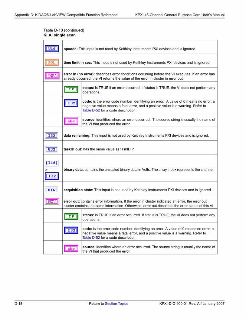
Appendix D: KIDAQ®-LabVIEW Compatible Function Reference KPXI 48-Channel General Purpose Card User’s Manual
opcode: This input is not used by Keithley Instruments PXI devices and is ignored.
time limit in sec: This input is not used by Keithley Instruments PXI devices and is ignored.
error in (no error): describes error conditions occurring before the VI executes. If an error has already occurred, the VI returns the value of the error in cluster in error out.
status: is TRUE if an error occurred. If status is TRUE, the VI does not perform any operations.
code: is the error code number identifying an error. A value of 0 means no error, a negative value means a fatal error, and a positive value is a warning. Refer to Table D-52 for a code description.
source: identifies where an error occurred. The source string is usually the name of the VI that produced the error.
data remaining: This input is not used by Keithley Instruments PXI devices and is ignored.
taskID out: has the same value as taskID in.
or binary data: contains the unscaled binary data in Volts. The array index represents the channel.
acquisition state: This input is not used by Keithley Instruments PXI devices and is ignored
error out: contains error information. If the error in cluster indicated an error, the error out cluster contains the same information. Otherwise, error out describes the error status of this VI.
status: is TRUE if an error occurred. If status is TRUE, the VI does not perform any operations.
code: is the error code number identifying an error. A value of 0 means no error, a negative value means a fatal error, and a positive value is a warning. Refer to Table D-52 for a code description.
source: identifies where an error occurred. The source string is usually the name of the VI that produced the error.
Table D-10 (continued)KI AI single scan
D-18 Return to Section Topics KPXI-DIO-900-01 Rev. A / January 2007
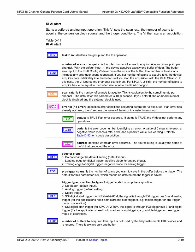
KP
KPXI 48-Channel General Purpose Card User’s Manual Appendix D: KIDAQ®-LabVIEW Compatible Function Reference
KI AI start
Starts a buffered analog input operation. This VI sets the scan rate, the number of scans to acquire, the conversion clock source, and the trigger conditions. The VI then starts an acquisition.
Table D-11 KI AI start
taskID in: identifies the group and the I/O operation.
number of scans to acquire: is the total number of scans to acquire. A scan is one point per channel. With the default input -1, the device acquires exactly one buffer of data. The buffer size input to the KI AI Config VI determines the size of the buffer. The number of total scans includes any pretrigger scans requested. If you set number of scans to acquire to 0, the device acquires data indefinitely into the buffer until you stop the acquisition with the KI AI Clear VI. In this case, the VI ignores the pretrigger scans input. For KPXI-AI-2-65M, the number of scans to acquire has to be equal to the buffer size input to the KI AI Config VI.
scan rate: is the number of scans/s to acquire. This is equivalent to the sampling rate per channel. The default for this parameter is 1000 scans/s. If you enter 0, the on-board internal clock is disabled and the external clock is used.
error in (no error): describes error conditions occurring before the VI executes. If an error has already occurred, the VI returns the value of the error in cluster in error out.
status: is TRUE if an error occurred. If status is TRUE, the VI does not perform any operations.
code: is the error code number identifying an error. A value of 0 means no error, a negative value means a fatal error, and a positive value is a warning. Refer to Table D-52 for a code description.
source: identifies where an error occurred. The source string is usually the name of the VI that produced the error.
edge or slope: 0: Do not change the default setting (default input).1: Leading edge for digital trigger; positive slope for analog trigger.2: Trailing edge for digital trigger; negative slope for analog trigger.
pretrigger scans: is the number of scans you want to save in the buffer before the trigger. The default for this parameter is 0, which means no data before the trigger is saved.
trigger type: specifies the type of trigger to start or stop the acquisition. 0: No trigger (default input).1: Analog trigger (default setting).2: Digital trigger.3: SSI digital start trigger (for KPXI-AI-2-65M, the signal is through PXI trigger bus 3) and analog trigger (for the applications need both start and stop triggers, e.g. middle trigger or pre-trigger mode of operation).4: SSI digital start trigger (for KPXI-AI-2-65M, the signal is through PXI trigger bus 3) and digital trigger (for the applications need both start and stop triggers, e.g. middle trigger or pre-trigger mode of operation).
number of buffers to acquire: This input is not used by Keithley Instruments PXI devices and is ignored. There is always only one buffer.
XI-DIO-900-01 Rev. A / January 2007 Return to Section Topics D-19
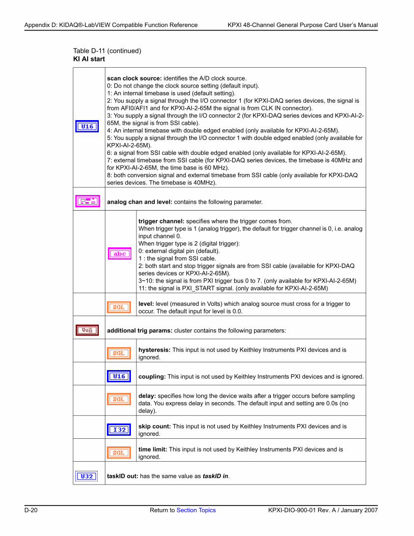
Appendix D: KIDAQ®-LabVIEW Compatible Function Reference KPXI 48-Channel General Purpose Card User’s Manual
scan clock source: identifies the A/D clock source. 0: Do not change the clock source setting (default input).1: An internal timebase is used (default setting).2: You supply a signal through the I/O connector 1 (for KPXI-DAQ series devices, the signal is from AFI0/AFI1 and for KPXI-AI-2-65M the signal is from CLK IN connector).3: You supply a signal through the I/O connector 2 (for KPXI-DAQ series devices and KPXI-AI-2-65M, the signal is from SSI cable).4: An internal timebase with double edged enabled (only available for KPXI-AI-2-65M).5: You supply a signal through the I/O connector 1 with double edged enabled (only available for KPXI-AI-2-65M).6: a signal from SSI cable with double edged enabled (only available for KPXI-AI-2-65M).7: external timebase from SSI cable (for KPXI-DAQ series devices, the timebase is 40MHz and for KPXI-AI-2-65M, the time base is 60 MHz).8: both conversion signal and external timebase from SSI cable (only available for KPXI-DAQ series devices. The timebase is 40MHz).
analog chan and level: contains the following parameter.
trigger channel: specifies where the trigger comes from.When trigger type is 1 (analog trigger), the default for trigger channel is 0, i.e. analog input channel 0.When trigger type is 2 (digital trigger):0: external digital pin (default). 1 : the signal from SSI cable. 2: both start and stop trigger signals are from SSI cable (available for KPXI-DAQ series devices or KPXI-AI-2-65M).3~10: the signal is from PXI trigger bus 0 to 7. (only available for KPXI-AI-2-65M)11: the signal is PXI_START signal. (only available for KPXI-AI-2-65M)
level: level (measured in Volts) which analog source must cross for a trigger to occur. The default input for level is 0.0.
additional trig params: cluster contains the following parameters:
hysteresis: This input is not used by Keithley Instruments PXI devices and is ignored.
coupling: This input is not used by Keithley Instruments PXI devices and is ignored.
delay: specifies how long the device waits after a trigger occurs before sampling data. You express delay in seconds. The default input and setting are 0.0s (no delay).
skip count: This input is not used by Keithley Instruments PXI devices and is ignored.
time limit: This input is not used by Keithley Instruments PXI devices and is ignored.
taskID out: has the same value as taskID in.
Table D-11 (continued)KI AI start
D-20 Return to Section Topics KPXI-DIO-900-01 Rev. A / January 2007
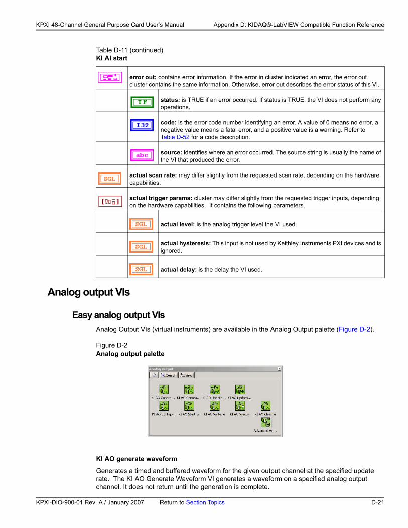
KP
KPXI 48-Channel General Purpose Card User’s Manual Appendix D: KIDAQ®-LabVIEW Compatible Function Reference
Analog output VIs
Easy analog output VIsAnalog Output VIs (virtual instruments) are available in the Analog Output palette (Figure D-2).
Figure D-2Analog output palette
KI AO generate waveform
Generates a timed and buffered waveform for the given output channel at the specified update rate. The KI AO Generate Waveform VI generates a waveform on a specified analog output channel. It does not return until the generation is complete.
error out: contains error information. If the error in cluster indicated an error, the error out cluster contains the same information. Otherwise, error out describes the error status of this VI.
status: is TRUE if an error occurred. If status is TRUE, the VI does not perform any operations.
code: is the error code number identifying an error. A value of 0 means no error, a negative value means a fatal error, and a positive value is a warning. Refer to Table D-52 for a code description.
source: identifies where an error occurred. The source string is usually the name of the VI that produced the error.
actual scan rate: may differ slightly from the requested scan rate, depending on the hardware capabilities.
actual trigger params: cluster may differ slightly from the requested trigger inputs, depending on the hardware capabilities. It contains the following parameters.
actual level: is the analog trigger level the VI used.
actual hysteresis: This input is not used by Keithley Instruments PXI devices and is ignored.
actual delay: is the delay the VI used.
Table D-11 (continued)KI AI start
XI-DIO-900-01 Rev. A / January 2007 Return to Section Topics D-21
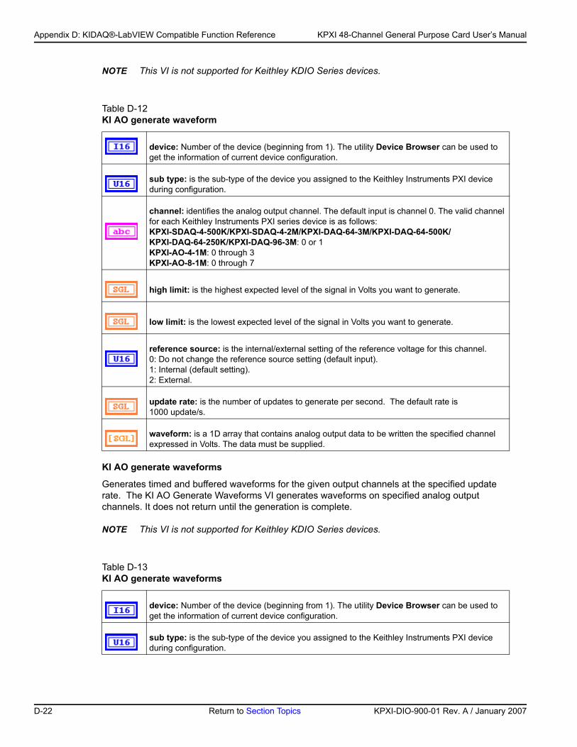
Appendix D: KIDAQ®-LabVIEW Compatible Function Reference KPXI 48-Channel General Purpose Card User’s Manual
NOTE This VI is not supported for Keithley KDIO Series devices.
KI AO generate waveforms
Generates timed and buffered waveforms for the given output channels at the specified update rate. The KI AO Generate Waveforms VI generates waveforms on specified analog output channels. It does not return until the generation is complete.
NOTE This VI is not supported for Keithley KDIO Series devices.
Table D-12 KI AO generate waveform
device: Number of the device (beginning from 1). The utility Device Browser can be used to get the information of current device configuration.
sub type: is the sub-type of the device you assigned to the Keithley Instruments PXI device during configuration.
channel: identifies the analog output channel. The default input is channel 0. The valid channel for each Keithley Instruments PXI series device is as follows:KPXI-SDAQ-4-500K/KPXI-SDAQ-4-2M/KPXI-DAQ-64-3M/KPXI-DAQ-64-500K/ KPXI-DAQ-64-250K/KPXI-DAQ-96-3M: 0 or 1KPXI-AO-4-1M: 0 through 3KPXI-AO-8-1M: 0 through 7
high limit: is the highest expected level of the signal in Volts you want to generate.
low limit: is the lowest expected level of the signal in Volts you want to generate.
reference source: is the internal/external setting of the reference voltage for this channel.0: Do not change the reference source setting (default input).1: Internal (default setting).2: External.
update rate: is the number of updates to generate per second. The default rate is 1000 update/s.
waveform: is a 1D array that contains analog output data to be written the specified channel expressed in Volts. The data must be supplied.
Table D-13 KI AO generate waveforms
device: Number of the device (beginning from 1). The utility Device Browser can be used to get the information of current device configuration.
sub type: is the sub-type of the device you assigned to the Keithley Instruments PXI device during configuration.
D-22 Return to Section Topics KPXI-DIO-900-01 Rev. A / January 2007
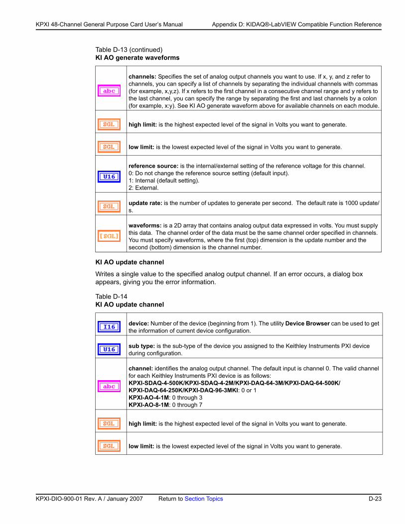
KP
KPXI 48-Channel General Purpose Card User’s Manual Appendix D: KIDAQ®-LabVIEW Compatible Function Reference
KI AO update channel
Writes a single value to the specified analog output channel. If an error occurs, a dialog box appears, giving you the error information.
channels: Specifies the set of analog output channels you want to use. If x, y, and z refer to channels, you can specify a list of channels by separating the individual channels with commas (for example, x,y,z). If x refers to the first channel in a consecutive channel range and y refers to the last channel, you can specify the range by separating the first and last channels by a colon (for example, x:y). See KI AO generate waveform above for available channels on each module.
high limit: is the highest expected level of the signal in Volts you want to generate.
low limit: is the lowest expected level of the signal in Volts you want to generate.
reference source: is the internal/external setting of the reference voltage for this channel.0: Do not change the reference source setting (default input).1: Internal (default setting).2: External.
update rate: is the number of updates to generate per second. The default rate is 1000 update/s.
waveforms: is a 2D array that contains analog output data expressed in volts. You must supply this data. The channel order of the data must be the same channel order specified in channels. You must specify waveforms, where the first (top) dimension is the update number and the second (bottom) dimension is the channel number.
Table D-14 KI AO update channel
device: Number of the device (beginning from 1). The utility Device Browser can be used to get the information of current device configuration.
sub type: is the sub-type of the device you assigned to the Keithley Instruments PXI device during configuration.
channel: identifies the analog output channel. The default input is channel 0. The valid channel for each Keithley Instruments PXI device is as follows:KPXI-SDAQ-4-500K/KPXI-SDAQ-4-2M/KPXI-DAQ-64-3M/KPXI-DAQ-64-500K/ KPXI-DAQ-64-250K/KPXI-DAQ-96-3MKI: 0 or 1KPXI-AO-4-1M: 0 through 3KPXI-AO-8-1M: 0 through 7
high limit: is the highest expected level of the signal in Volts you want to generate.
low limit: is the lowest expected level of the signal in Volts you want to generate.
Table D-13 (continued)KI AO generate waveforms
XI-DIO-900-01 Rev. A / January 2007 Return to Section Topics D-23
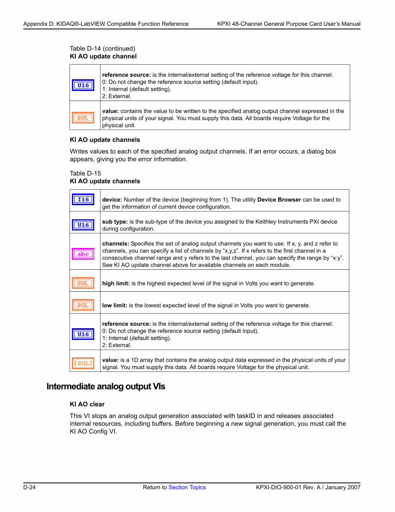
Appendix D: KIDAQ®-LabVIEW Compatible Function Reference KPXI 48-Channel General Purpose Card User’s Manual
KI AO update channels
Writes values to each of the specified analog output channels. If an error occurs, a dialog box appears, giving you the error information.
Intermediate analog output VIs
KI AO clear
This VI stops an analog output generation associated with taskID in and releases associated internal resources, including buffers. Before beginning a new signal generation, you must call the KI AO Config VI.
reference source: is the internal/external setting of the reference voltage for this channel.0: Do not change the reference source setting (default input).1: Internal (default setting).2: External.
value: contains the value to be written to the specified analog output channel expressed in the physical units of your signal. You must supply this data. All boards require Voltage for the physical unit.
Table D-15 KI AO update channels
device: Number of the device (beginning from 1). The utility Device Browser can be used to get the information of current device configuration.
sub type: is the sub-type of the device you assigned to the Keithley Instruments PXI device during configuration.
channels: Specifies the set of analog output channels you want to use. If x, y, and z refer to channels, you can specify a list of channels by “x,y,z”. If x refers to the first channel in a consecutive channel range and y refers to the last channel, you can specify the range by “x:y”. See KI AO update channel above for available channels on each module.
high limit: is the highest expected level of the signal in Volts you want to generate.
low limit: is the lowest expected level of the signal in Volts you want to generate.
reference source: is the internal/external setting of the reference voltage for this channel.0: Do not change the reference source setting (default input).1: Internal (default setting).2: External.
value: is a 1D array that contains the analog output data expressed in the physical units of your signal. You must supply this data. All boards require Voltage for the physical unit.
Table D-14 (continued)KI AO update channel
D-24 Return to Section Topics KPXI-DIO-900-01 Rev. A / January 2007
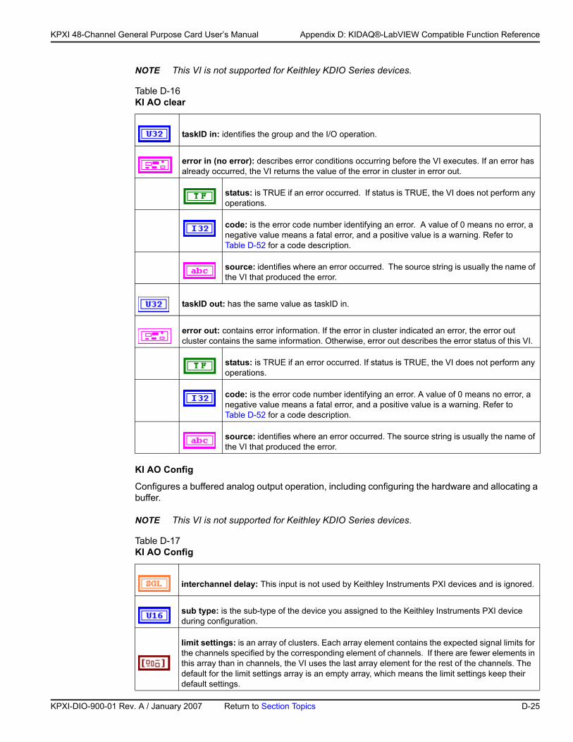
KP
KPXI 48-Channel General Purpose Card User’s Manual Appendix D: KIDAQ®-LabVIEW Compatible Function Reference
NOTE This VI is not supported for Keithley KDIO Series devices.
KI AO Config
Configures a buffered analog output operation, including configuring the hardware and allocating a buffer.
NOTE This VI is not supported for Keithley KDIO Series devices.
Table D-16 KI AO clear
taskID in: identifies the group and the I/O operation.
error in (no error): describes error conditions occurring before the VI executes. If an error has already occurred, the VI returns the value of the error in cluster in error out.
status: is TRUE if an error occurred. If status is TRUE, the VI does not perform any operations.
code: is the error code number identifying an error. A value of 0 means no error, a negative value means a fatal error, and a positive value is a warning. Refer to Table D-52 for a code description.
source: identifies where an error occurred. The source string is usually the name of the VI that produced the error.
taskID out: has the same value as taskID in.
error out: contains error information. If the error in cluster indicated an error, the error out cluster contains the same information. Otherwise, error out describes the error status of this VI.
status: is TRUE if an error occurred. If status is TRUE, the VI does not perform any operations.
code: is the error code number identifying an error. A value of 0 means no error, a negative value means a fatal error, and a positive value is a warning. Refer to Table D-52 for a code description.
source: identifies where an error occurred. The source string is usually the name of the VI that produced the error.
Table D-17 KI AO Config
interchannel delay: This input is not used by Keithley Instruments PXI devices and is ignored.
sub type: is the sub-type of the device you assigned to the Keithley Instruments PXI device during configuration.
limit settings: is an array of clusters. Each array element contains the expected signal limits for the channels specified by the corresponding element of channels. If there are fewer elements in this array than in channels, the VI uses the last array element for the rest of the channels. The default for the limit settings array is an empty array, which means the limit settings keep their default settings.
XI-DIO-900-01 Rev. A / January 2007 Return to Section Topics D-25
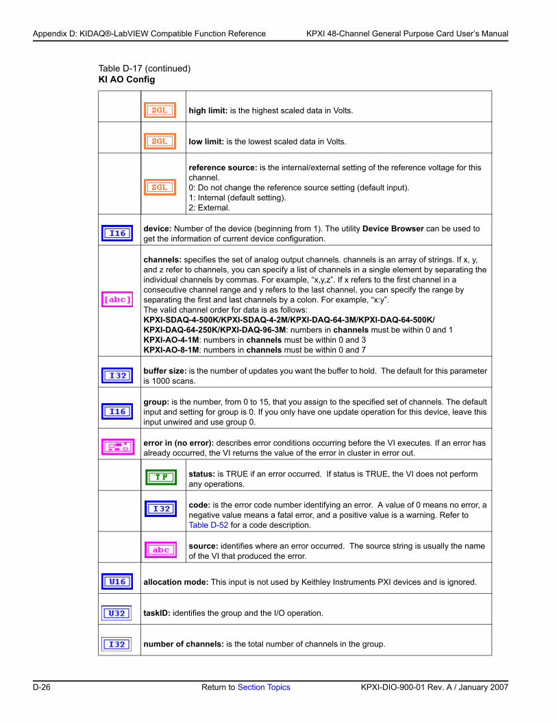
Appendix D: KIDAQ®-LabVIEW Compatible Function Reference KPXI 48-Channel General Purpose Card User’s Manual
high limit: is the highest scaled data in Volts.
low limit: is the lowest scaled data in Volts.
reference source: is the internal/external setting of the reference voltage for this channel.0: Do not change the reference source setting (default input).1: Internal (default setting).2: External.
device: Number of the device (beginning from 1). The utility Device Browser can be used to get the information of current device configuration.
channels: specifies the set of analog output channels. channels is an array of strings. If x, y, and z refer to channels, you can specify a list of channels in a single element by separating the individual channels by commas. For example, “x,y,z”. If x refers to the first channel in a consecutive channel range and y refers to the last channel, you can specify the range by separating the first and last channels by a colon. For example, “x:y”.The valid channel order for data is as follows:KPXI-SDAQ-4-500K/KPXI-SDAQ-4-2M/KPXI-DAQ-64-3M/KPXI-DAQ-64-500K/ KPXI-DAQ-64-250K/KPXI-DAQ-96-3M: numbers in channels must be within 0 and 1KPXI-AO-4-1M: numbers in channels must be within 0 and 3KPXI-AO-8-1M: numbers in channels must be within 0 and 7
buffer size: is the number of updates you want the buffer to hold. The default for this parameter is 1000 scans.
group: is the number, from 0 to 15, that you assign to the specified set of channels. The default input and setting for group is 0. If you only have one update operation for this device, leave this input unwired and use group 0.
error in (no error): describes error conditions occurring before the VI executes. If an error has already occurred, the VI returns the value of the error in cluster in error out.
status: is TRUE if an error occurred. If status is TRUE, the VI does not perform any operations.
code: is the error code number identifying an error. A value of 0 means no error, a negative value means a fatal error, and a positive value is a warning. Refer to Table D-52 for a code description.
source: identifies where an error occurred. The source string is usually the name of the VI that produced the error.
allocation mode: This input is not used by Keithley Instruments PXI devices and is ignored.
taskID: identifies the group and the I/O operation.
number of channels: is the total number of channels in the group.
Table D-17 (continued)KI AO Config
D-26 Return to Section Topics KPXI-DIO-900-01 Rev. A / January 2007
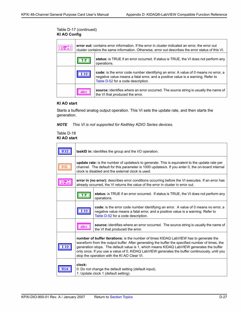
KP
KPXI 48-Channel General Purpose Card User’s Manual Appendix D: KIDAQ®-LabVIEW Compatible Function Reference
KI AO start
Starts a buffered analog output operation. This VI sets the update rate, and then starts the generation.
NOTE This VI is not supported for Keithley KDIO Series devices.
error out: contains error information. If the error in cluster indicated an error, the error out cluster contains the same information. Otherwise, error out describes the error status of this VI.
status: is TRUE if an error occurred. If status is TRUE, the VI does not perform any operations.
code: is the error code number identifying an error. A value of 0 means no error, a negative value means a fatal error, and a positive value is a warning. Refer to Table D-52 for a code description.
source: identifies where an error occurred. The source string is usually the name of the VI that produced the error.
Table D-18 KI AO start
taskID in: identifies the group and the I/O operation.
update rate: is the number of updates/s to generate. This is equivalent to the update rate per channel. The default for this parameter is 1000 updates/s. If you enter 0, the on-board internal clock is disabled and the external clock is used.
error in (no error): describes error conditions occurring before the VI executes. If an error has already occurred, the VI returns the value of the error in cluster in error out.
status: is TRUE if an error occurred. If status is TRUE, the VI does not perform any operations.
code: is the error code number identifying an error. A value of 0 means no error, a negative value means a fatal error, and a positive value is a warning. Refer to Table D-52 for a code description.
source: identifies where an error occurred. The source string is usually the name of the VI that produced the error.
number of buffer iterations: is the number of times KIDAQ LabVIEW has to generate the waveform from the output buffer. After generating the buffer the specified number of times, the generation stops. The default value is 1, which means KIDAQ LabVIEW generates the buffer only once. If you use a value of 0, KIDAQ LabVIEW generates the buffer continuously, until you stop the operation with the KI AO Clear VI.
clock: 0: Do not change the default setting (default input).1: Update clock 1 (default setting).
Table D-17 (continued)KI AO Config
XI-DIO-900-01 Rev. A / January 2007 Return to Section Topics D-27
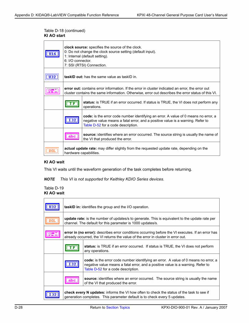
Appendix D: KIDAQ®-LabVIEW Compatible Function Reference KPXI 48-Channel General Purpose Card User’s Manual
KI AO wait
This VI waits until the waveform generation of the task completes before returning.
NOTE This VI is not supported for Keithley KDIO Series devices.
clock source: specifies the source of the clock. 0: Do not change the clock source setting (default input).1: Internal (default setting).6: I/O connector.7: SSI (RTSI) Connection.
taskID out: has the same value as taskID in.
error out: contains error information. If the error in cluster indicated an error, the error out cluster contains the same information. Otherwise, error out describes the error status of this VI.
status: is TRUE if an error occurred. If status is TRUE, the VI does not perform any operations.
code: is the error code number identifying an error. A value of 0 means no error, a negative value means a fatal error, and a positive value is a warning. Refer to Table D-52 for a code description.
source: identifies where an error occurred. The source string is usually the name of the VI that produced the error.
actual update rate: may differ slightly from the requested update rate, depending on the hardware capabilities.
Table D-19 KI AO wait
taskID in: identifies the group and the I/O operation.
update rate: is the number of updates/s to generate. This is equivalent to the update rate per channel. The default for this parameter is 1000 updates/s.
error in (no error): describes error conditions occurring before the VI executes. If an error has already occurred, the VI returns the value of the error in cluster in error out.
status: is TRUE if an error occurred. If status is TRUE, the VI does not perform any operations.
code: is the error code number identifying an error. A value of 0 means no error, a negative value means a fatal error, and a positive value is a warning. Refer to Table D-52 for a code description.
source: identifies where an error occurred. The source string is usually the name of the VI that produced the error.
check every N updates: informs the VI how often to check the status of the task to see if generation completes. This parameter default is to check every 5 updates.
Table D-18 (continued)KI AO start
D-28 Return to Section Topics KPXI-DIO-900-01 Rev. A / January 2007
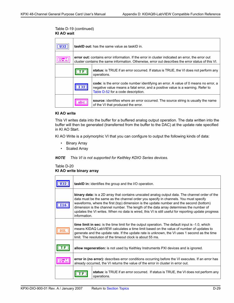
KP
KPXI 48-Channel General Purpose Card User’s Manual Appendix D: KIDAQ®-LabVIEW Compatible Function Reference
KI AO write
This VI writes data into the buffer for a buffered analog output operation. The data written into the buffer will then be generated (transferred from the buffer to the DAC) at the update rate specified in KI AO Start.
KI AO Write is a polymorphic VI that you can configure to output the following kinds of data:
• Binary Array• Scaled Array
NOTE This VI is not supported for Keithley KDIO Series devices.
taskID out: has the same value as taskID in.
error out: contains error information. If the error in cluster indicated an error, the error out cluster contains the same information. Otherwise, error out describes the error status of this VI.
status: is TRUE if an error occurred. If status is TRUE, the VI does not perform any operations.
code: is the error code number identifying an error. A value of 0 means no error, a negative value means a fatal error, and a positive value is a warning. Refer to Table D-52 for a code description.
source: identifies where an error occurred. The source string is usually the name of the VI that produced the error.
Table D-20 KI AO write binary array
taskID in: identifies the group and the I/O operation.
binary data: is a 2D array that contains unscaled analog output data. The channel order of the data must be the same as the channel order you specify in channels. You must specify waveforms, where the first (top) dimension is the update number and the second (bottom) dimension is the channel number. The length of the data array determines the number of updates the VI writes. When no data is wired, this VI is still useful for reporting update progress information.
time limit in sec: is the time limit for the output operation. The default input is -1.0, which means KIDAQ LabVIEW calculates a time limit based on the value of number of updates to generate and the update rate. If the update rate is unknown, the VI uses 1 second as the time limit. The resolution of the timeout clock is about 55 ms.
allow regeneration: is not used by Keithley Instruments PXI devices and is ignored.
error in (no error): describes error conditions occurring before the VI executes. If an error has already occurred, the VI returns the value of the error in cluster in error out.
status: is TRUE if an error occurred. If status is TRUE, the VI does not perform any operations.
Table D-19 (continued)KI AO wait
XI-DIO-900-01 Rev. A / January 2007 Return to Section Topics D-29
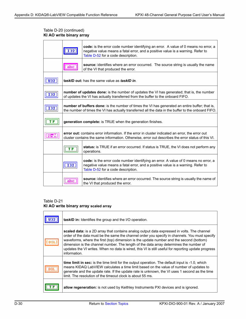
Appendix D: KIDAQ®-LabVIEW Compatible Function Reference KPXI 48-Channel General Purpose Card User’s Manual
code: is the error code number identifying an error. A value of 0 means no error, a negative value means a fatal error, and a positive value is a warning. Refer to Table D-52 for a code description.
source: identifies where an error occurred. The source string is usually the name of the VI that produced the error.
taskID out: has the same value as taskID in.
number of updates done: is the number of updates the VI has generated; that is, the number of updates the VI has actually transferred from the buffer to the onboard FIFO.
number of buffers done: is the number of times the VI has generated an entire buffer; that is, the number of times the VI has actually transferred all the data in the buffer to the onboard FIFO.
generation complete: is TRUE when the generation finishes.
error out: contains error information. If the error in cluster indicated an error, the error out cluster contains the same information. Otherwise, error out describes the error status of this VI.
status: is TRUE if an error occurred. If status is TRUE, the VI does not perform any operations.
code: is the error code number identifying an error. A value of 0 means no error, a negative value means a fatal error, and a positive value is a warning. Refer to Table D-52 for a code description.
source: identifies where an error occurred. The source string is usually the name of the VI that produced the error.
Table D-21 KI AO write binary array scaled array
taskID in: Identifies the group and the I/O operation.
scaled data: is a 2D array that contains analog output data expressed in volts. The channel order of the data must be the same the channel order you specify in channels. You must specify waveforms, where the first (top) dimension is the update number and the second (bottom) dimension is the channel number. The length of the data array determines the number of updates the VI writes. When no data is wired, this VI is still useful for reporting update progress information.
time limit in sec: is the time limit for the output operation. The default input is -1.0, which means KIDAQ LabVIEW calculates a time limit based on the value of number of updates to generate and the update rate. If the update rate is unknown, the VI uses 1 second as the time limit. The resolution of the timeout clock is about 55 ms.
allow regeneration: is not used by Keithley Instruments PXI devices and is ignored.
Table D-20 (continued)KI AO write binary array
D-30 Return to Section Topics KPXI-DIO-900-01 Rev. A / January 2007
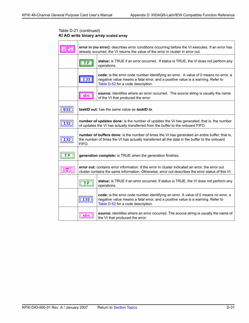
KP
KPXI 48-Channel General Purpose Card User’s Manual Appendix D: KIDAQ®-LabVIEW Compatible Function Reference
error in (no error): describes error conditions occurring before the VI executes. If an error has already occurred, the VI returns the value of the error in cluster in error out.
status: is TRUE if an error occurred. If status is TRUE, the VI does not perform any operations.
code: is the error code number identifying an error. A value of 0 means no error, a negative value means a fatal error, and a positive value is a warning. Refer to Table D-52 for a code description.
source: Identifies where an error occurred. The source string is usually the name of the VI that produced the error.
taskID out: has the same value as taskID in.
number of updates done: is the number of updates the VI has generated; that is, the number of updates the VI has actually transferred from the buffer to the onboard FIFO.
number of buffers done: is the number of times the VI has generated an entire buffer; that is, the number of times the VI has actually transferred all the data in the buffer to the onboard FIFO.
generation complete: is TRUE when the generation finishes.
error out: contains error information. If the error in cluster indicated an error, the error out cluster contains the same information. Otherwise, error out describes the error status of this VI.
status: is TRUE if an error occurred. If status is TRUE, the VI does not perform any operations.
code: is the error code number identifying an error. A value of 0 means no error, a negative value means a fatal error, and a positive value is a warning. Refer to Table D-52 for a code description.
source: identifies where an error occurred. The source string is usually the name of the VI that produced the error.
Table D-21 (continued)KI AO write binary array scaled array
XI-DIO-900-01 Rev. A / January 2007 Return to Section Topics D-31
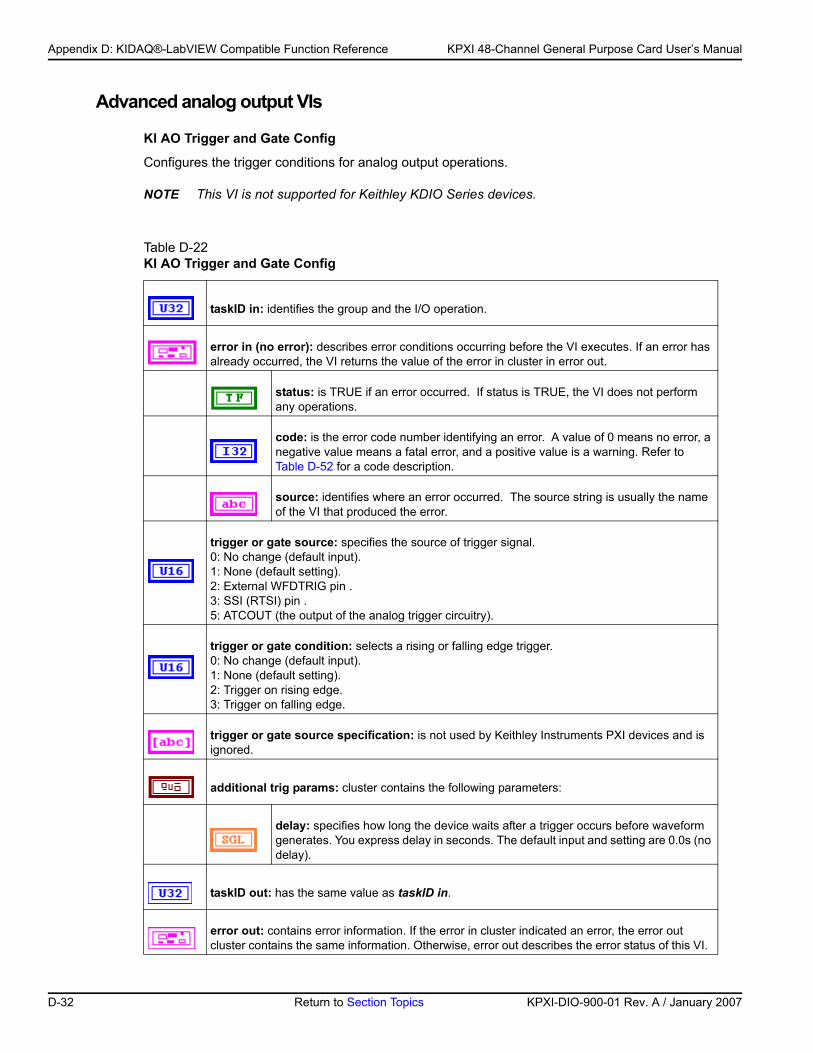
Appendix D: KIDAQ®-LabVIEW Compatible Function Reference KPXI 48-Channel General Purpose Card User’s Manual
Advanced analog output VIs
KI AO Trigger and Gate Config
Configures the trigger conditions for analog output operations.
NOTE This VI is not supported for Keithley KDIO Series devices.
Table D-22 KI AO Trigger and Gate Config
taskID in: identifies the group and the I/O operation.
error in (no error): describes error conditions occurring before the VI executes. If an error has already occurred, the VI returns the value of the error in cluster in error out.
status: is TRUE if an error occurred. If status is TRUE, the VI does not perform any operations.
code: is the error code number identifying an error. A value of 0 means no error, a negative value means a fatal error, and a positive value is a warning. Refer to Table D-52 for a code description.
source: identifies where an error occurred. The source string is usually the name of the VI that produced the error.
trigger or gate source: specifies the source of trigger signal. 0: No change (default input).1: None (default setting).2: External WFDTRIG pin .3: SSI (RTSI) pin .5: ATCOUT (the output of the analog trigger circuitry).
trigger or gate condition: selects a rising or falling edge trigger. 0: No change (default input).1: None (default setting).2: Trigger on rising edge.3: Trigger on falling edge.
trigger or gate source specification: is not used by Keithley Instruments PXI devices and is ignored.
additional trig params: cluster contains the following parameters:
delay: specifies how long the device waits after a trigger occurs before waveform generates. You express delay in seconds. The default input and setting are 0.0s (no delay).
taskID out: has the same value as taskID in.
error out: contains error information. If the error in cluster indicated an error, the error out cluster contains the same information. Otherwise, error out describes the error status of this VI.
D-32 Return to Section Topics KPXI-DIO-900-01 Rev. A / January 2007
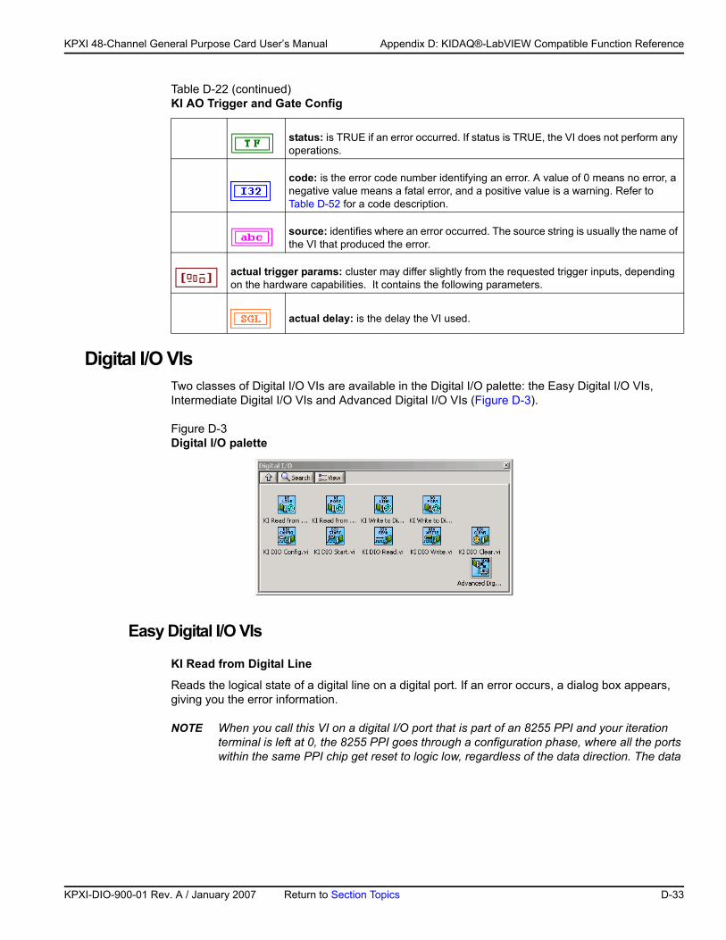
KP
KPXI 48-Channel General Purpose Card User’s Manual Appendix D: KIDAQ®-LabVIEW Compatible Function Reference
Digital I/O VIsTwo classes of Digital I/O VIs are available in the Digital I/O palette: the Easy Digital I/O VIs, Intermediate Digital I/O VIs and Advanced Digital I/O VIs (Figure D-3).
Figure D-3Digital I/O palette
Easy Digital I/O VIs
KI Read from Digital Line
Reads the logical state of a digital line on a digital port. If an error occurs, a dialog box appears, giving you the error information.
NOTE When you call this VI on a digital I/O port that is part of an 8255 PPI and your iteration terminal is left at 0, the 8255 PPI goes through a configuration phase, where all the ports within the same PPI chip get reset to logic low, regardless of the data direction. The data
status: is TRUE if an error occurred. If status is TRUE, the VI does not perform any operations.
code: is the error code number identifying an error. A value of 0 means no error, a negative value means a fatal error, and a positive value is a warning. Refer to Table D-52 for a code description.
source: identifies where an error occurred. The source string is usually the name of the VI that produced the error.
actual trigger params: cluster may differ slightly from the requested trigger inputs, depending on the hardware capabilities. It contains the following parameters.
actual delay: is the delay the VI used.
Table D-22 (continued)KI AO Trigger and Gate Config
XI-DIO-900-01 Rev. A / January 2007 Return to Section Topics D-33
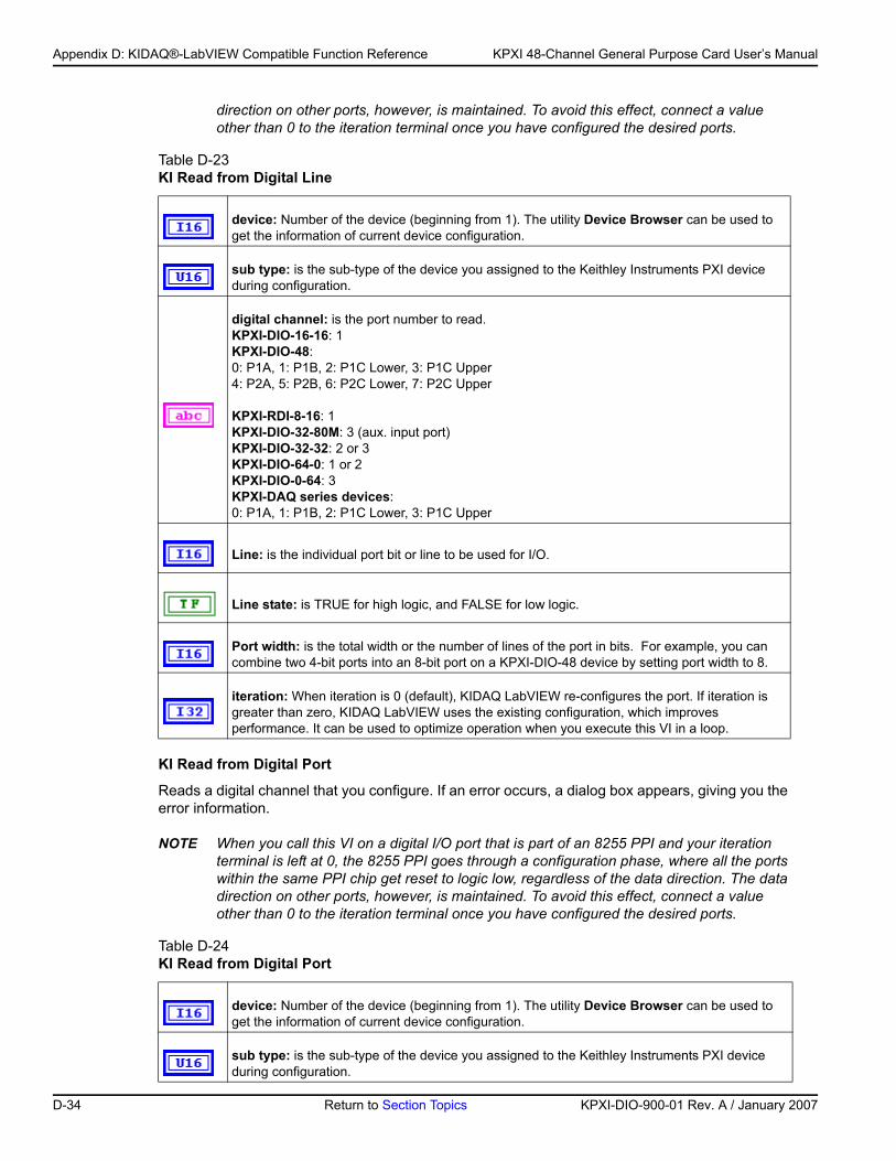
Appendix D: KIDAQ®-LabVIEW Compatible Function Reference KPXI 48-Channel General Purpose Card User’s Manual
direction on other ports, however, is maintained. To avoid this effect, connect a value other than 0 to the iteration terminal once you have configured the desired ports.
KI Read from Digital Port
Reads a digital channel that you configure. If an error occurs, a dialog box appears, giving you the error information.
NOTE When you call this VI on a digital I/O port that is part of an 8255 PPI and your iteration terminal is left at 0, the 8255 PPI goes through a configuration phase, where all the ports within the same PPI chip get reset to logic low, regardless of the data direction. The data direction on other ports, however, is maintained. To avoid this effect, connect a value other than 0 to the iteration terminal once you have configured the desired ports.
Table D-23 KI Read from Digital Line
device: Number of the device (beginning from 1). The utility Device Browser can be used to get the information of current device configuration.
sub type: is the sub-type of the device you assigned to the Keithley Instruments PXI device during configuration.
digital channel: is the port number to read.KPXI-DIO-16-16: 1KPXI-DIO-48:0: P1A, 1: P1B, 2: P1C Lower, 3: P1C Upper4: P2A, 5: P2B, 6: P2C Lower, 7: P2C Upper
KPXI-RDI-8-16: 1KPXI-DIO-32-80M: 3 (aux. input port)KPXI-DIO-32-32: 2 or 3KPXI-DIO-64-0: 1 or 2KPXI-DIO-0-64: 3KPXI-DAQ series devices:0: P1A, 1: P1B, 2: P1C Lower, 3: P1C Upper
Line: is the individual port bit or line to be used for I/O.
Line state: is TRUE for high logic, and FALSE for low logic.
Port width: is the total width or the number of lines of the port in bits. For example, you can combine two 4-bit ports into an 8-bit port on a KPXI-DIO-48 device by setting port width to 8.
iteration: When iteration is 0 (default), KIDAQ LabVIEW re-configures the port. If iteration is greater than zero, KIDAQ LabVIEW uses the existing configuration, which improves performance. It can be used to optimize operation when you execute this VI in a loop.
Table D-24 KI Read from Digital Port
device: Number of the device (beginning from 1). The utility Device Browser can be used to get the information of current device configuration.
sub type: is the sub-type of the device you assigned to the Keithley Instruments PXI device during configuration.
D-34 Return to Section Topics KPXI-DIO-900-01 Rev. A / January 2007
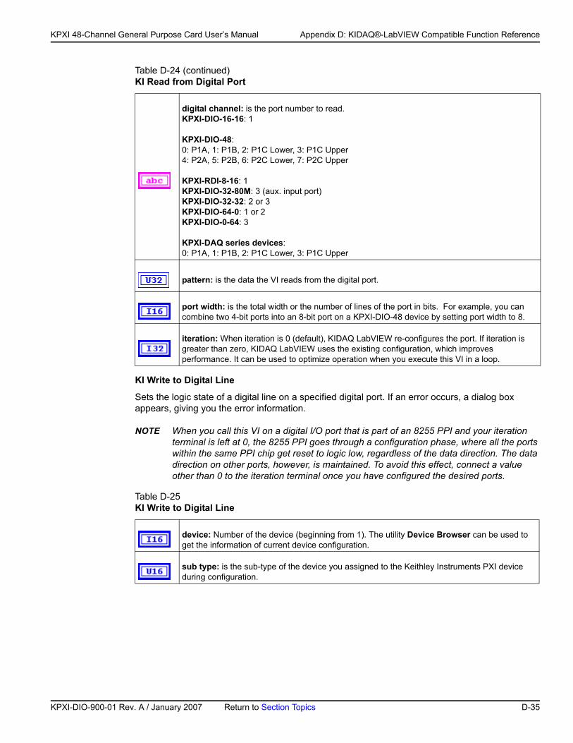
KP
KPXI 48-Channel General Purpose Card User’s Manual Appendix D: KIDAQ®-LabVIEW Compatible Function Reference
KI Write to Digital Line
Sets the logic state of a digital line on a specified digital port. If an error occurs, a dialog box appears, giving you the error information.
NOTE When you call this VI on a digital I/O port that is part of an 8255 PPI and your iteration terminal is left at 0, the 8255 PPI goes through a configuration phase, where all the ports within the same PPI chip get reset to logic low, regardless of the data direction. The data direction on other ports, however, is maintained. To avoid this effect, connect a value other than 0 to the iteration terminal once you have configured the desired ports.
digital channel: is the port number to read.KPXI-DIO-16-16: 1
KPXI-DIO-48:0: P1A, 1: P1B, 2: P1C Lower, 3: P1C Upper4: P2A, 5: P2B, 6: P2C Lower, 7: P2C Upper
KPXI-RDI-8-16: 1KPXI-DIO-32-80M: 3 (aux. input port)KPXI-DIO-32-32: 2 or 3KPXI-DIO-64-0: 1 or 2KPXI-DIO-0-64: 3
KPXI-DAQ series devices:0: P1A, 1: P1B, 2: P1C Lower, 3: P1C Upper
pattern: is the data the VI reads from the digital port.
port width: is the total width or the number of lines of the port in bits. For example, you can combine two 4-bit ports into an 8-bit port on a KPXI-DIO-48 device by setting port width to 8.
iteration: When iteration is 0 (default), KIDAQ LabVIEW re-configures the port. If iteration is greater than zero, KIDAQ LabVIEW uses the existing configuration, which improves performance. It can be used to optimize operation when you execute this VI in a loop.
Table D-25 KI Write to Digital Line
device: Number of the device (beginning from 1). The utility Device Browser can be used to get the information of current device configuration.
sub type: is the sub-type of the device you assigned to the Keithley Instruments PXI device during configuration.
Table D-24 (continued)KI Read from Digital Port
XI-DIO-900-01 Rev. A / January 2007 Return to Section Topics D-35
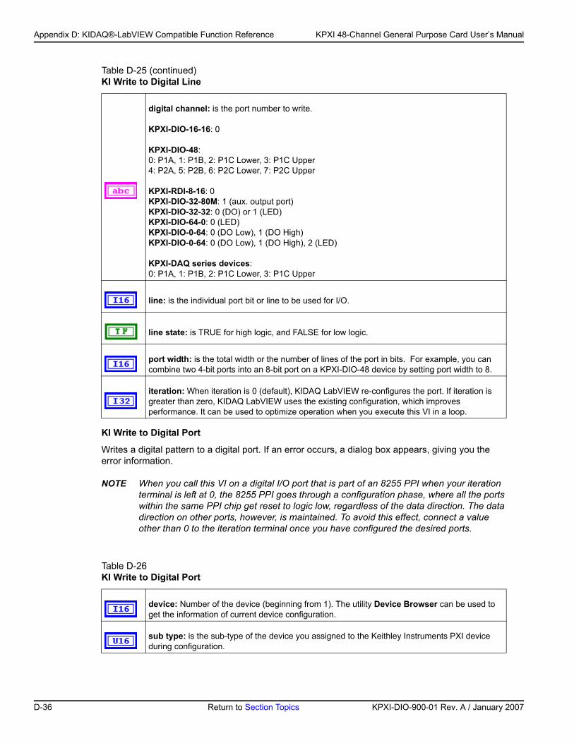
Appendix D: KIDAQ®-LabVIEW Compatible Function Reference KPXI 48-Channel General Purpose Card User’s Manual
KI Write to Digital Port
Writes a digital pattern to a digital port. If an error occurs, a dialog box appears, giving you the error information.
NOTE When you call this VI on a digital I/O port that is part of an 8255 PPI when your iteration terminal is left at 0, the 8255 PPI goes through a configuration phase, where all the ports within the same PPI chip get reset to logic low, regardless of the data direction. The data direction on other ports, however, is maintained. To avoid this effect, connect a value other than 0 to the iteration terminal once you have configured the desired ports.
digital channel: is the port number to write.
KPXI-DIO-16-16: 0
KPXI-DIO-48:0: P1A, 1: P1B, 2: P1C Lower, 3: P1C Upper4: P2A, 5: P2B, 6: P2C Lower, 7: P2C Upper
KPXI-RDI-8-16: 0KPXI-DIO-32-80M: 1 (aux. output port)KPXI-DIO-32-32: 0 (DO) or 1 (LED)KPXI-DIO-64-0: 0 (LED)KPXI-DIO-0-64: 0 (DO Low), 1 (DO High)KPXI-DIO-0-64: 0 (DO Low), 1 (DO High), 2 (LED)
KPXI-DAQ series devices:0: P1A, 1: P1B, 2: P1C Lower, 3: P1C Upper
line: is the individual port bit or line to be used for I/O.
line state: is TRUE for high logic, and FALSE for low logic.
port width: is the total width or the number of lines of the port in bits. For example, you can combine two 4-bit ports into an 8-bit port on a KPXI-DIO-48 device by setting port width to 8.
iteration: When iteration is 0 (default), KIDAQ LabVIEW re-configures the port. If iteration is greater than zero, KIDAQ LabVIEW uses the existing configuration, which improves performance. It can be used to optimize operation when you execute this VI in a loop.
Table D-26 KI Write to Digital Port
device: Number of the device (beginning from 1). The utility Device Browser can be used to get the information of current device configuration.
sub type: is the sub-type of the device you assigned to the Keithley Instruments PXI device during configuration.
Table D-25 (continued)KI Write to Digital Line
D-36 Return to Section Topics KPXI-DIO-900-01 Rev. A / January 2007
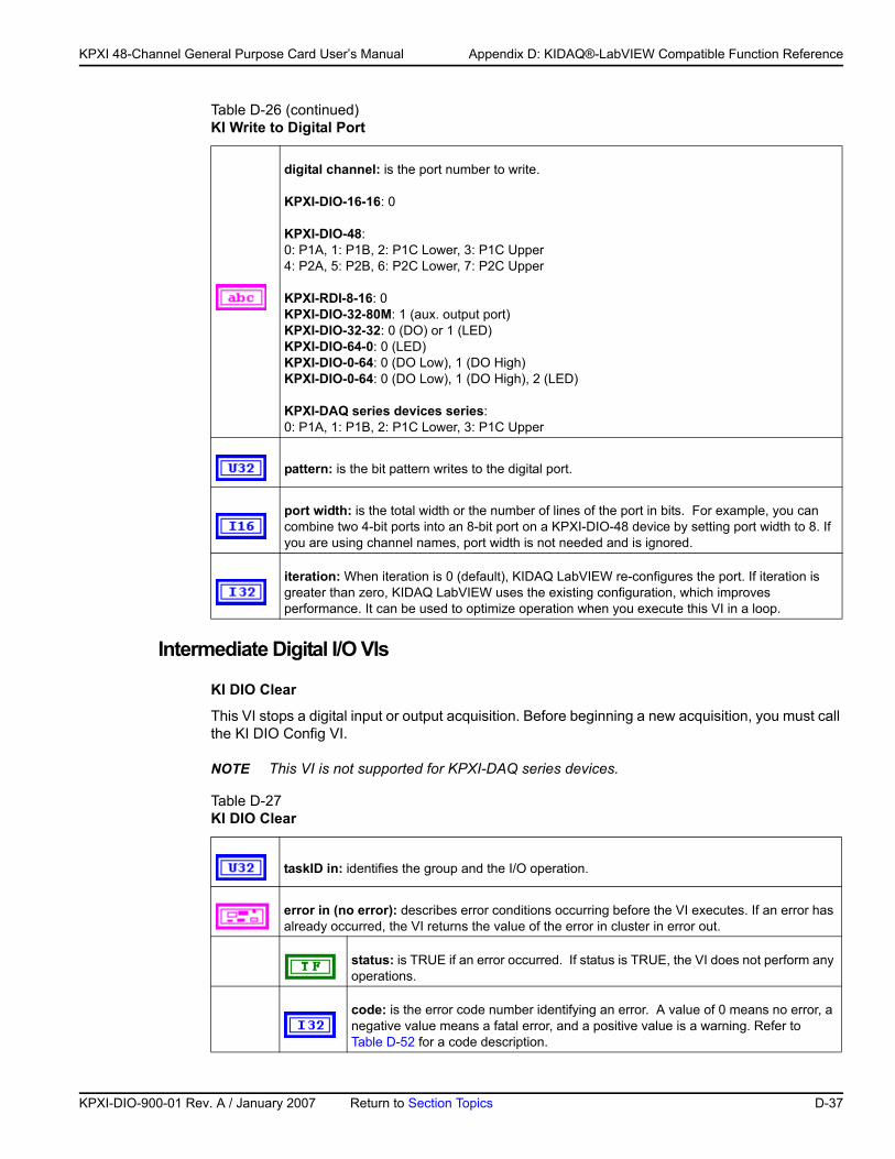
KP
KPXI 48-Channel General Purpose Card User’s Manual Appendix D: KIDAQ®-LabVIEW Compatible Function Reference
Intermediate Digital I/O VIs
KI DIO Clear
This VI stops a digital input or output acquisition. Before beginning a new acquisition, you must call the KI DIO Config VI.
NOTE This VI is not supported for KPXI-DAQ series devices.
digital channel: is the port number to write.
KPXI-DIO-16-16: 0
KPXI-DIO-48:0: P1A, 1: P1B, 2: P1C Lower, 3: P1C Upper4: P2A, 5: P2B, 6: P2C Lower, 7: P2C Upper
KPXI-RDI-8-16: 0KPXI-DIO-32-80M: 1 (aux. output port)KPXI-DIO-32-32: 0 (DO) or 1 (LED)KPXI-DIO-64-0: 0 (LED)KPXI-DIO-0-64: 0 (DO Low), 1 (DO High)KPXI-DIO-0-64: 0 (DO Low), 1 (DO High), 2 (LED)
KPXI-DAQ series devices series:0: P1A, 1: P1B, 2: P1C Lower, 3: P1C Upper
pattern: is the bit pattern writes to the digital port.
port width: is the total width or the number of lines of the port in bits. For example, you can combine two 4-bit ports into an 8-bit port on a KPXI-DIO-48 device by setting port width to 8. If you are using channel names, port width is not needed and is ignored.
iteration: When iteration is 0 (default), KIDAQ LabVIEW re-configures the port. If iteration is greater than zero, KIDAQ LabVIEW uses the existing configuration, which improves performance. It can be used to optimize operation when you execute this VI in a loop.
Table D-27 KI DIO Clear
taskID in: identifies the group and the I/O operation.
error in (no error): describes error conditions occurring before the VI executes. If an error has already occurred, the VI returns the value of the error in cluster in error out.
status: is TRUE if an error occurred. If status is TRUE, the VI does not perform any operations.
code: is the error code number identifying an error. A value of 0 means no error, a negative value means a fatal error, and a positive value is a warning. Refer to Table D-52 for a code description.
Table D-26 (continued)KI Write to Digital Port
XI-DIO-900-01 Rev. A / January 2007 Return to Section Topics D-37
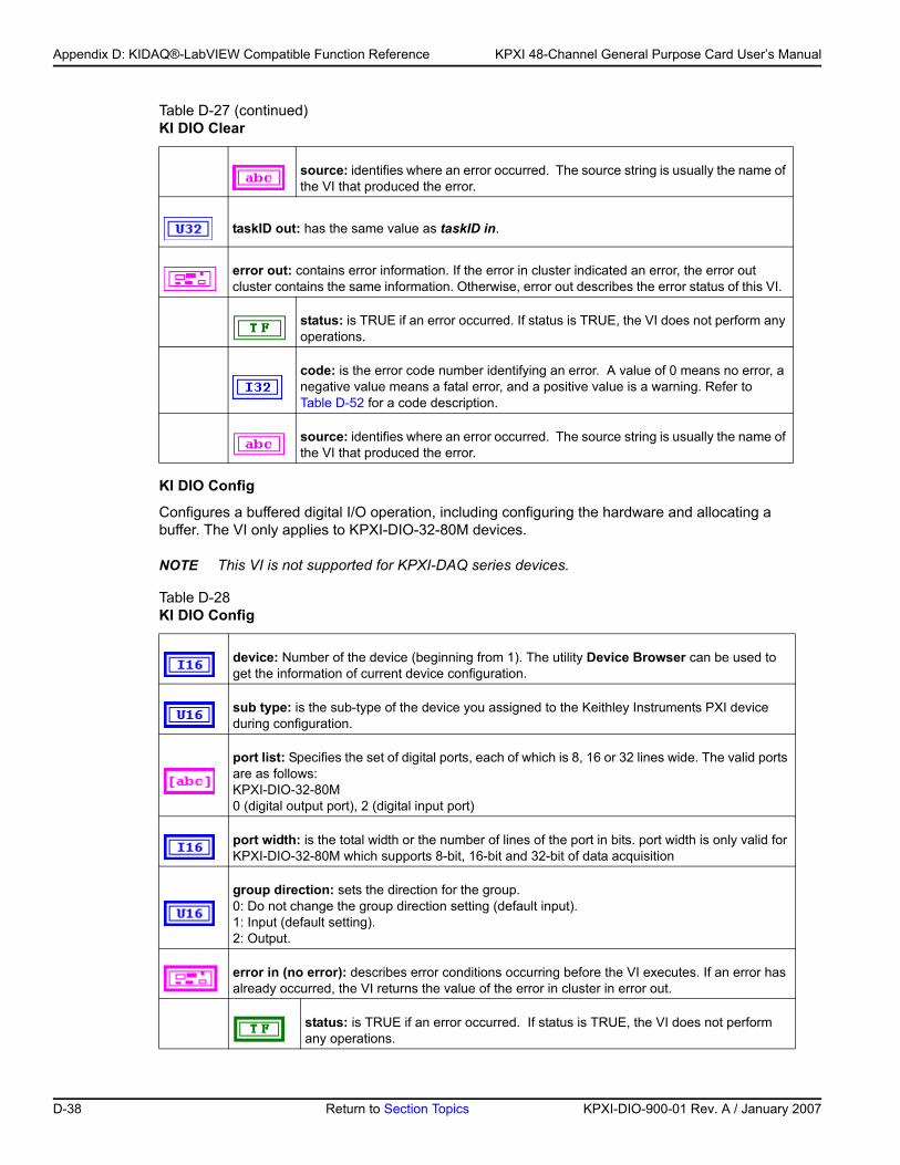
Appendix D: KIDAQ®-LabVIEW Compatible Function Reference KPXI 48-Channel General Purpose Card User’s Manual
KI DIO Config
Configures a buffered digital I/O operation, including configuring the hardware and allocating a buffer. The VI only applies to KPXI-DIO-32-80M devices.
NOTE This VI is not supported for KPXI-DAQ series devices.
source: identifies where an error occurred. The source string is usually the name of the VI that produced the error.
taskID out: has the same value as taskID in.
error out: contains error information. If the error in cluster indicated an error, the error out cluster contains the same information. Otherwise, error out describes the error status of this VI.
status: is TRUE if an error occurred. If status is TRUE, the VI does not perform any operations.
code: is the error code number identifying an error. A value of 0 means no error, a negative value means a fatal error, and a positive value is a warning. Refer to Table D-52 for a code description.
source: identifies where an error occurred. The source string is usually the name of the VI that produced the error.
Table D-28 KI DIO Config
device: Number of the device (beginning from 1). The utility Device Browser can be used to get the information of current device configuration.
sub type: is the sub-type of the device you assigned to the Keithley Instruments PXI device during configuration.
port list: Specifies the set of digital ports, each of which is 8, 16 or 32 lines wide. The valid ports are as follows:KPXI-DIO-32-80M0 (digital output port), 2 (digital input port)
port width: is the total width or the number of lines of the port in bits. port width is only valid for KPXI-DIO-32-80M which supports 8-bit, 16-bit and 32-bit of data acquisition
group direction: sets the direction for the group. 0: Do not change the group direction setting (default input).1: Input (default setting).2: Output.
error in (no error): describes error conditions occurring before the VI executes. If an error has already occurred, the VI returns the value of the error in cluster in error out.
status: is TRUE if an error occurred. If status is TRUE, the VI does not perform any operations.
Table D-27 (continued)KI DIO Clear
D-38 Return to Section Topics KPXI-DIO-900-01 Rev. A / January 2007
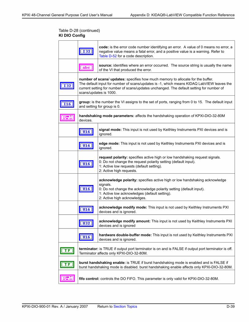
KP
KPXI 48-Channel General Purpose Card User’s Manual Appendix D: KIDAQ®-LabVIEW Compatible Function Reference
code: is the error code number identifying an error. A value of 0 means no error, a negative value means a fatal error, and a positive value is a warning. Refer to Table D-52 for a code description.
source: identifies where an error occurred. The source string is usually the name of the VI that produced the error.
number of scans/ updates: specifies how much memory to allocate for the buffer. The default input for number of scans/updates is -1, which means KIDAQ LabVIEW leaves the current setting for number of scans/updates unchanged. The default setting for number of scans/updates is 1000.
group: is the number the VI assigns to the set of ports, ranging from 0 to 15. The default input and setting for group is 0.
handshaking mode parameters: affects the handshaking operation of KPXI-DIO-32-80M devices.
signal mode: This input is not used by Keithley Instruments PXI devices and is ignored.
edge mode: This input is not used by Keithley Instruments PXI devices and is ignored.
request polarity: specifies active high or low handshaking request signals. 0: Do not change the request polarity setting (default input).1: Active low requests (default setting).2: Active high requests.
acknowledge polarity: specifies active high or low handshaking acknowledge signals. 0: Do not change the acknowledge polarity setting (default input).1: Active low acknowledges (default setting).2: Active high acknowledges.
acknowledge modify mode: This input is not used by Keithley Instruments PXI devices and is ignored.
acknowledge modify amount: This input is not used by Keithley Instruments PXI devices and is ignored
hardware double-buffer mode: This input is not used by Keithley Instruments PXI devices and is ignored.
terminator: is TRUE if output port terminator is on and is FALSE if output port terminator is off. Terminator affects only KPXI-DIO-32-80M.
burst handshaking enable: is TRUE if burst handshaking mode is enabled and is FALSE if burst handshaking mode is disabled. burst handshaking enable affects only KPXI-DIO-32-80M.
fifo control: controls the DO FIFO. This parameter is only valid for KPXI-DIO-32-80M.
Table D-28 (continued)KI DIO Config
XI-DIO-900-01 Rev. A / January 2007 Return to Section Topics D-39
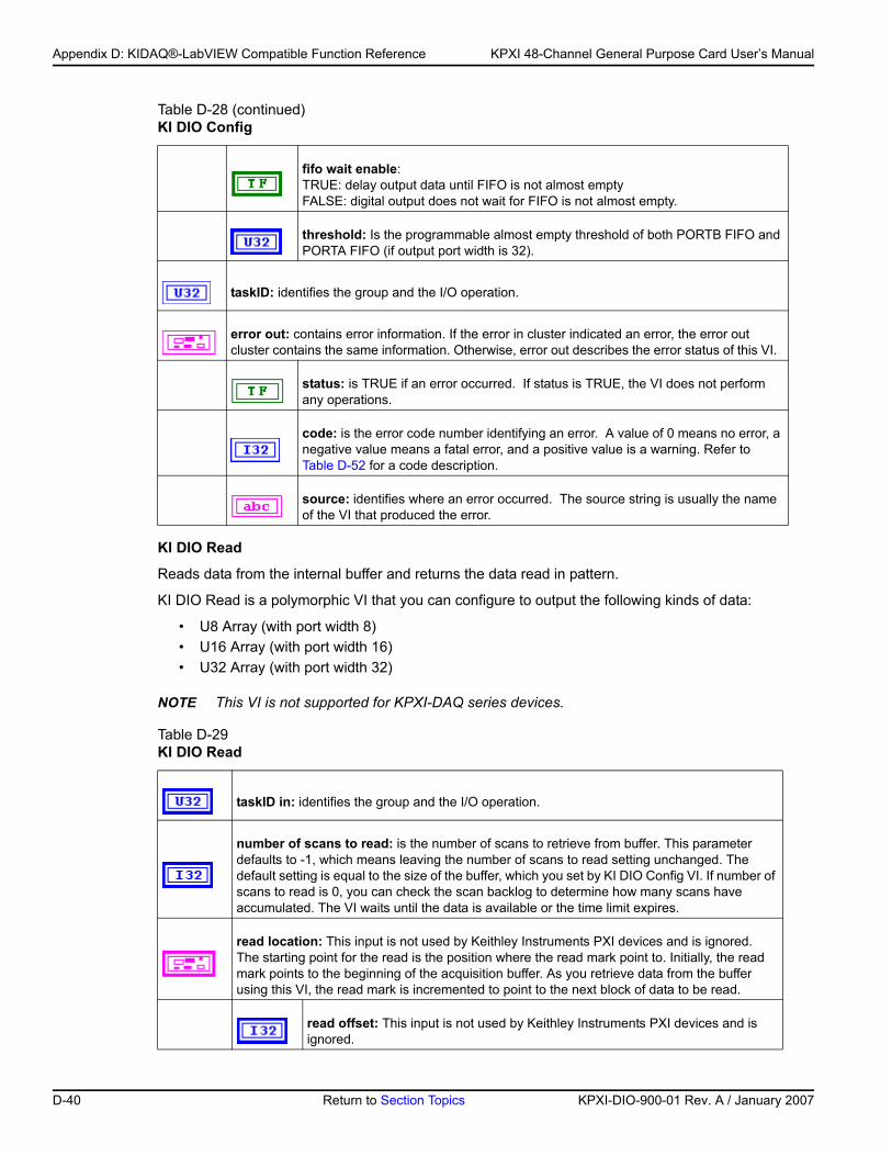
Appendix D: KIDAQ®-LabVIEW Compatible Function Reference KPXI 48-Channel General Purpose Card User’s Manual
KI DIO Read
Reads data from the internal buffer and returns the data read in pattern.
KI DIO Read is a polymorphic VI that you can configure to output the following kinds of data:
• U8 Array (with port width 8)• U16 Array (with port width 16)• U32 Array (with port width 32)
NOTE This VI is not supported for KPXI-DAQ series devices.
fifo wait enable:TRUE: delay output data until FIFO is not almost emptyFALSE: digital output does not wait for FIFO is not almost empty.
threshold: Is the programmable almost empty threshold of both PORTB FIFO and PORTA FIFO (if output port width is 32).
taskID: identifies the group and the I/O operation.
error out: contains error information. If the error in cluster indicated an error, the error out cluster contains the same information. Otherwise, error out describes the error status of this VI.
status: is TRUE if an error occurred. If status is TRUE, the VI does not perform any operations.
code: is the error code number identifying an error. A value of 0 means no error, a negative value means a fatal error, and a positive value is a warning. Refer to Table D-52 for a code description.
source: identifies where an error occurred. The source string is usually the name of the VI that produced the error.
Table D-29 KI DIO Read
taskID in: identifies the group and the I/O operation.
number of scans to read: is the number of scans to retrieve from buffer. This parameter defaults to -1, which means leaving the number of scans to read setting unchanged. The default setting is equal to the size of the buffer, which you set by KI DIO Config VI. If number of scans to read is 0, you can check the scan backlog to determine how many scans have accumulated. The VI waits until the data is available or the time limit expires.
read location: This input is not used by Keithley Instruments PXI devices and is ignored.The starting point for the read is the position where the read mark point to. Initially, the read mark points to the beginning of the acquisition buffer. As you retrieve data from the buffer using this VI, the read mark is incremented to point to the next block of data to be read.
read offset: This input is not used by Keithley Instruments PXI devices and is ignored.
Table D-28 (continued)KI DIO Config
D-40 Return to Section Topics KPXI-DIO-900-01 Rev. A / January 2007
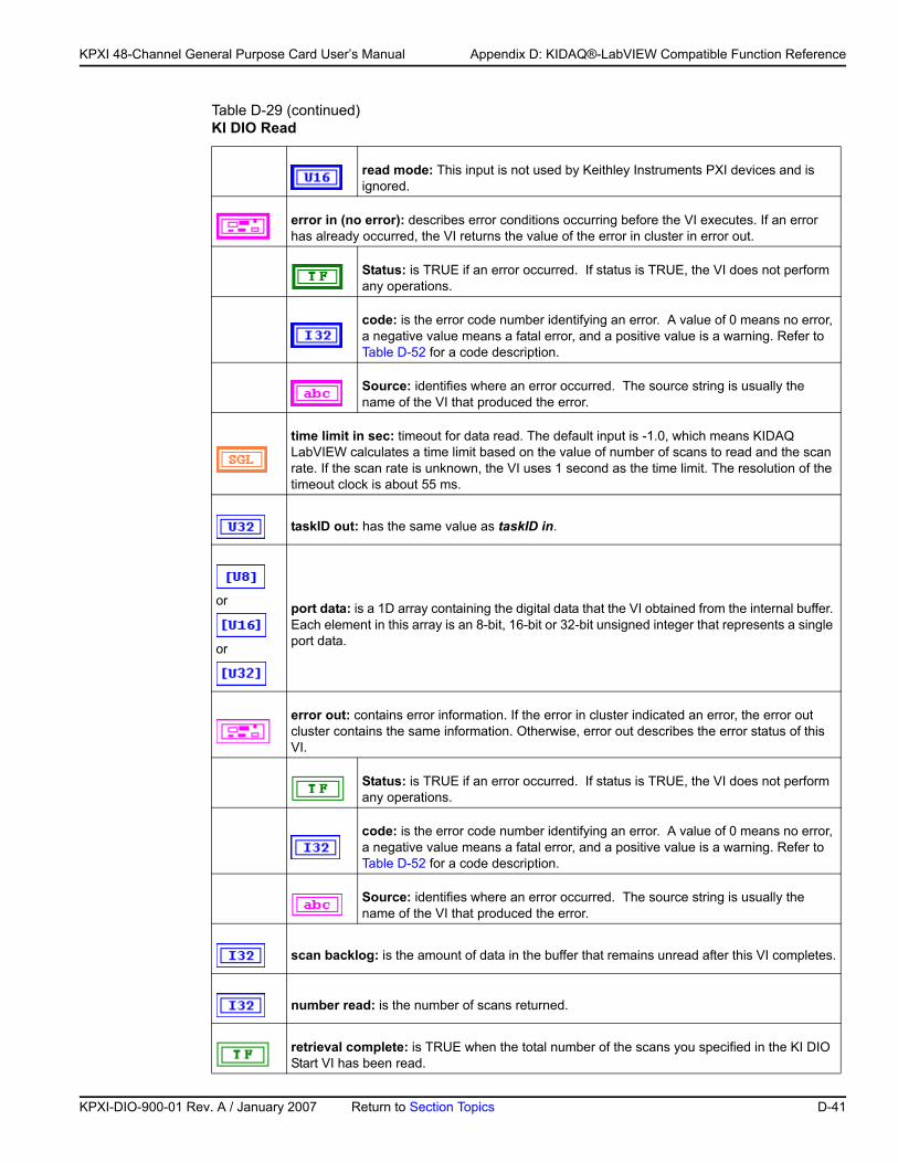
KP
KPXI 48-Channel General Purpose Card User’s Manual Appendix D: KIDAQ®-LabVIEW Compatible Function Reference
read mode: This input is not used by Keithley Instruments PXI devices and is ignored.
error in (no error): describes error conditions occurring before the VI executes. If an error has already occurred, the VI returns the value of the error in cluster in error out.
Status: is TRUE if an error occurred. If status is TRUE, the VI does not perform any operations.
code: is the error code number identifying an error. A value of 0 means no error, a negative value means a fatal error, and a positive value is a warning. Refer to Table D-52 for a code description.
Source: identifies where an error occurred. The source string is usually the name of the VI that produced the error.
time limit in sec: timeout for data read. The default input is -1.0, which means KIDAQ LabVIEW calculates a time limit based on the value of number of scans to read and the scan rate. If the scan rate is unknown, the VI uses 1 second as the time limit. The resolution of the timeout clock is about 55 ms.
taskID out: has the same value as taskID in.
or
or
port data: is a 1D array containing the digital data that the VI obtained from the internal buffer. Each element in this array is an 8-bit, 16-bit or 32-bit unsigned integer that represents a single port data.
error out: contains error information. If the error in cluster indicated an error, the error out cluster contains the same information. Otherwise, error out describes the error status of this VI.
Status: is TRUE if an error occurred. If status is TRUE, the VI does not perform any operations.
code: is the error code number identifying an error. A value of 0 means no error, a negative value means a fatal error, and a positive value is a warning. Refer to Table D-52 for a code description.
Source: identifies where an error occurred. The source string is usually the name of the VI that produced the error.
scan backlog: is the amount of data in the buffer that remains unread after this VI completes.
number read: is the number of scans returned.
retrieval complete: is TRUE when the total number of the scans you specified in the KI DIO Start VI has been read.
Table D-29 (continued)KI DIO Read
XI-DIO-900-01 Rev. A / January 2007 Return to Section Topics D-41
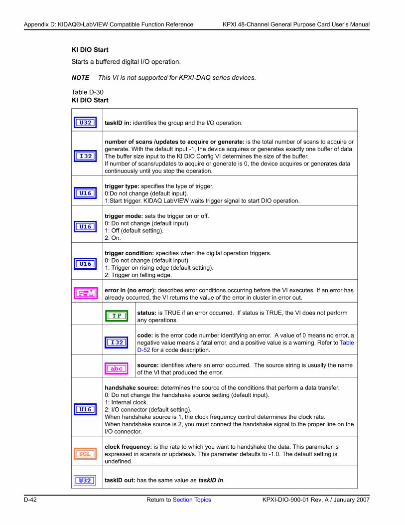
Appendix D: KIDAQ®-LabVIEW Compatible Function Reference KPXI 48-Channel General Purpose Card User’s Manual
KI DIO Start
Starts a buffered digital I/O operation.
NOTE This VI is not supported for KPXI-DAQ series devices.
Table D-30 KI DIO Start
taskID in: identifies the group and the I/O operation.
number of scans /updates to acquire or generate: is the total number of scans to acquire or generate. With the default input -1, the device acquires or generates exactly one buffer of data. The buffer size input to the KI DIO Config VI determines the size of the buffer. If number of scans/updates to acquire or generate is 0, the device acquires or generates data continuously until you stop the operation.
trigger type: specifies the type of trigger. 0:Do not change (default input). 1:Start trigger. KIDAQ LabVIEW waits trigger signal to start DIO operation.
trigger mode: sets the trigger on or off. 0: Do not change (default input).1: Off (default setting).2: On.
trigger condition: specifies when the digital operation triggers. 0: Do not change (default input). 1: Trigger on rising edge (default setting).2: Trigger on falling edge.
error in (no error): describes error conditions occurring before the VI executes. If an error has already occurred, the VI returns the value of the error in cluster in error out.
status: is TRUE if an error occurred. If status is TRUE, the VI does not perform any operations.
code: is the error code number identifying an error. A value of 0 means no error, a negative value means a fatal error, and a positive value is a warning. Refer to Table D-52 for a code description.
source: identifies where an error occurred. The source string is usually the name of the VI that produced the error.
handshake source: determines the source of the conditions that perform a data transfer. 0: Do not change the handshake source setting (default input). 1: Internal clock.2: I/O connector (default setting).When handshake source is 1, the clock frequency control determines the clock rate. When handshake source is 2, you must connect the handshake signal to the proper line on the I/O connector.
clock frequency: is the rate to which you want to handshake the data. This parameter is expressed in scans/s or updates/s. This parameter defaults to -1.0. The default setting is undefined.
taskID out: has the same value as taskID in.
D-42 Return to Section Topics KPXI-DIO-900-01 Rev. A / January 2007
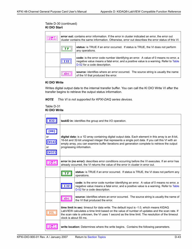
KP
KPXI 48-Channel General Purpose Card User’s Manual Appendix D: KIDAQ®-LabVIEW Compatible Function Reference
KI DIO Write
Writes digital output data to the internal transfer buffer. You can call the KI DIO Write VI after the transfer begins to retrieve the output status information.
NOTE This VI is not supported for KPXI-DAQ series devices.
error out: contains error information. If the error in cluster indicated an error, the error out cluster contains the same information. Otherwise, error out describes the error status of this VI.
status: is TRUE if an error occurred. If status is TRUE, the VI does not perform any operations.
code: is the error code number identifying an error. A value of 0 means no error, a negative value means a fatal error, and a positive value is a warning. Refer to Table D-52 for a code description.
source: identifies where an error occurred. The source string is usually the name of the VI that produced the error.
Table D-31 KI DIO Write
taskID in: identifies the group and the I/O operation.
or
or
digital data: is a 1D array containing digital output data. Each element in this array is an 8-bit, 16-bit and 32-bit unsigned integer that represents a single port data. If you call this VI with an empty array, you can examine buffer iterations and generation complete to retrieve the output progressing information.
error in (no error): describes error conditions occurring before the VI executes. If an error has already occurred, the VI returns the value of the error in cluster in error out.
status: is TRUE if an error occurred. If status is TRUE, the VI does not perform any operations.
code: is the error code number identifying an error. A value of 0 means no error, a negative value means a fatal error, and a positive value is a warning. Refer to Table D-52 for a code description.
source: identifies where an error occurred. The source string is usually the name of the VI that produced the error.
time limit in sec: timeout for data write. The default input is -1.0, which means KIDAQ LabVIEW calculates a time limit based on the value of number of updates and the scan rate. If the scan rate is unknown, the VI uses 1 second as the time limit. The resolution of the timeout clock is about 55 ms.
write location: Determines where the write begins. Contains the following parameters.
Table D-30 (continued)KI DIO Start
XI-DIO-900-01 Rev. A / January 2007 Return to Section Topics D-43
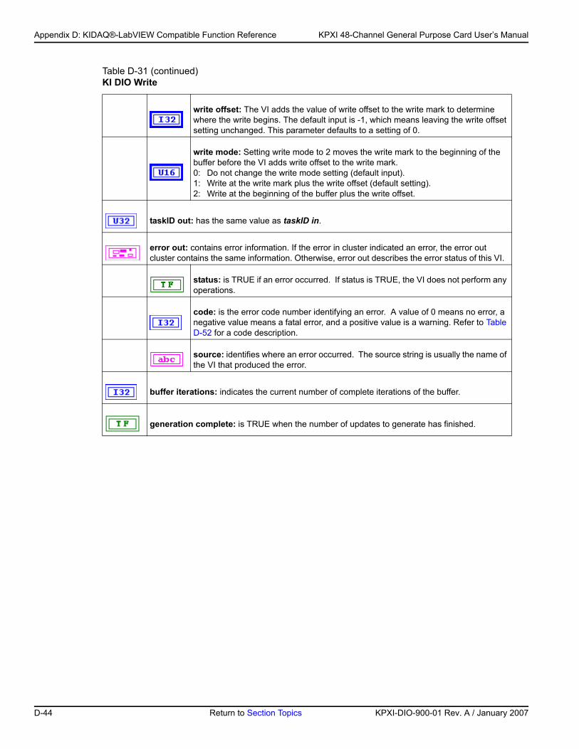
Appendix D: KIDAQ®-LabVIEW Compatible Function Reference KPXI 48-Channel General Purpose Card User’s Manual
write offset: The VI adds the value of write offset to the write mark to determine where the write begins. The default input is -1, which means leaving the write offset setting unchanged. This parameter defaults to a setting of 0.
write mode: Setting write mode to 2 moves the write mark to the beginning of the buffer before the VI adds write offset to the write mark.0: Do not change the write mode setting (default input). 1: Write at the write mark plus the write offset (default setting). 2: Write at the beginning of the buffer plus the write offset.
taskID out: has the same value as taskID in.
error out: contains error information. If the error in cluster indicated an error, the error out cluster contains the same information. Otherwise, error out describes the error status of this VI.
status: is TRUE if an error occurred. If status is TRUE, the VI does not perform any operations.
code: is the error code number identifying an error. A value of 0 means no error, a negative value means a fatal error, and a positive value is a warning. Refer to Table D-52 for a code description.
source: identifies where an error occurred. The source string is usually the name of the VI that produced the error.
buffer iterations: indicates the current number of complete iterations of the buffer.
generation complete: is TRUE when the number of updates to generate has finished.
Table D-31 (continued)KI DIO Write
D-44 Return to Section Topics KPXI-DIO-900-01 Rev. A / January 2007
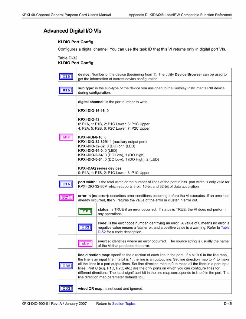
KP
KPXI 48-Channel General Purpose Card User’s Manual Appendix D: KIDAQ®-LabVIEW Compatible Function Reference
Advanced Digital I/O VIs
KI DIO Port Config
Configures a digital channel. You can use the task ID that this VI returns only in digital port VIs.
Table D-32 KI DIO Port Config
device: Number of the device (beginning from 1). The utility Device Browser can be used to get the information of current device configuration.
sub type: is the sub-type of the device you assigned to the Keithley Instruments PXI device during configuration.
digital channel: is the port number to write.
KPXI-DIO-16-16: 0
KPXI-DIO-48:0: P1A, 1: P1B, 2: P1C Lower, 3: P1C Upper4: P2A, 5: P2B, 6: P2C Lower, 7: P2C Upper
KPXI-RDI-8-16: 0KPXI-DIO-32-80M: 1 (auxiliary output port)KPXI-DIO-32-32: 0 (DO) or 1 (LED)KPXI-DIO-64-0: 0 (LED)KPXI-DIO-0-64: 0 (DO Low), 1 (DO High)KPXI-DIO-0-64: 0 (DO Low), 1 (DO High), 2 (LED)
KPXI-DAQ series devices:0: P1A, 1: P1B, 2: P1C Lower, 3: P1C Upper
port width: is the total width or the number of lines of the port in bits. port width is only valid for KPXI-DIO-32-80M which supports 8-bit, 16-bit and 32-bit of data acquisition
error in (no error): describes error conditions occurring before the VI executes. If an error has already occurred, the VI returns the value of the error in cluster in error out.
status: is TRUE if an error occurred. If status is TRUE, the VI does not perform any operations.
code: is the error code number identifying an error. A value of 0 means no error, a negative value means a fatal error, and a positive value is a warning. Refer to Table D-52 for a code description.
source: identifies where an error occurred. The source string is usually the name of the VI that produced the error.
line direction map: specifies the direction of each line in the port. If a bit is 0 in the line map, the line is an input line. If a bit is 1, the line is an output line. Set line direction map to -1 to make all the lines in a port output lines. Set line direction map to 0 to make all the lines in a port input lines. Port C (e.g. P1C, P2C, etc.) are the only ports on which you can configure lines for different directions. The least significant bit in the line map corresponds to line 0 in the port. The line direction map parameter defaults to 0.
wired OR map: is not used and ignored.
XI-DIO-900-01 Rev. A / January 2007 Return to Section Topics D-45
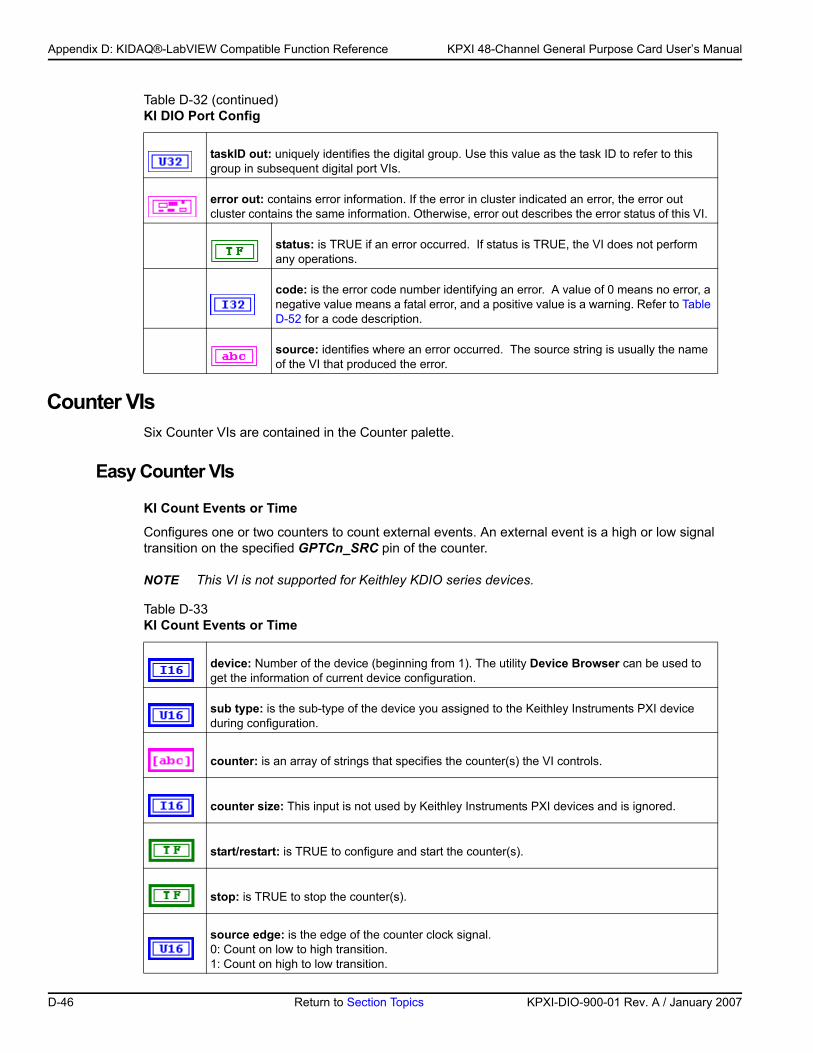
Appendix D: KIDAQ®-LabVIEW Compatible Function Reference KPXI 48-Channel General Purpose Card User’s Manual
Counter VIsSix Counter VIs are contained in the Counter palette.
Easy Counter VIs
KI Count Events or Time
Configures one or two counters to count external events. An external event is a high or low signal transition on the specified GPTCn_SRC pin of the counter.
NOTE This VI is not supported for Keithley KDIO series devices.
taskID out: uniquely identifies the digital group. Use this value as the task ID to refer to this group in subsequent digital port VIs.
error out: contains error information. If the error in cluster indicated an error, the error out cluster contains the same information. Otherwise, error out describes the error status of this VI.
status: is TRUE if an error occurred. If status is TRUE, the VI does not perform any operations.
code: is the error code number identifying an error. A value of 0 means no error, a negative value means a fatal error, and a positive value is a warning. Refer to Table D-52 for a code description.
source: identifies where an error occurred. The source string is usually the name of the VI that produced the error.
Table D-33 KI Count Events or Time
device: Number of the device (beginning from 1). The utility Device Browser can be used to get the information of current device configuration.
sub type: is the sub-type of the device you assigned to the Keithley Instruments PXI device during configuration.
counter: is an array of strings that specifies the counter(s) the VI controls.
counter size: This input is not used by Keithley Instruments PXI devices and is ignored.
start/restart: is TRUE to configure and start the counter(s).
stop: is TRUE to stop the counter(s).
source edge: is the edge of the counter clock signal.0: Count on low to high transition.1: Count on high to low transition.
Table D-32 (continued)KI DIO Port Config
D-46 Return to Section Topics KPXI-DIO-900-01 Rev. A / January 2007
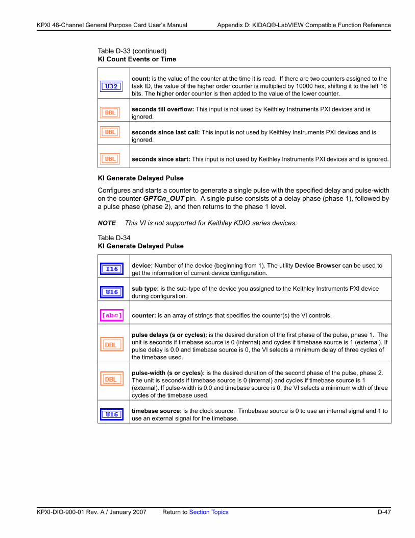
KP
KPXI 48-Channel General Purpose Card User’s Manual Appendix D: KIDAQ®-LabVIEW Compatible Function Reference
KI Generate Delayed Pulse
Configures and starts a counter to generate a single pulse with the specified delay and pulse-width on the counter GPTCn_OUT pin. A single pulse consists of a delay phase (phase 1), followed by a pulse phase (phase 2), and then returns to the phase 1 level.
NOTE This VI is not supported for Keithley KDIO series devices.
count: is the value of the counter at the time it is read. If there are two counters assigned to the task ID, the value of the higher order counter is multiplied by 10000 hex, shifting it to the left 16 bits. The higher order counter is then added to the value of the lower counter.
seconds till overflow: This input is not used by Keithley Instruments PXI devices and is ignored.
seconds since last call: This input is not used by Keithley Instruments PXI devices and is ignored.
seconds since start: This input is not used by Keithley Instruments PXI devices and is ignored.
Table D-34 KI Generate Delayed Pulse
device: Number of the device (beginning from 1). The utility Device Browser can be used to get the information of current device configuration.
sub type: is the sub-type of the device you assigned to the Keithley Instruments PXI device during configuration.
counter: is an array of strings that specifies the counter(s) the VI controls.
pulse delays (s or cycles): is the desired duration of the first phase of the pulse, phase 1. The unit is seconds if timebase source is 0 (internal) and cycles if timebase source is 1 (external). If pulse delay is 0.0 and timebase source is 0, the VI selects a minimum delay of three cycles of the timebase used.
pulse-width (s or cycles): is the desired duration of the second phase of the pulse, phase 2. The unit is seconds if timebase source is 0 (internal) and cycles if timebase source is 1 (external). If pulse-width is 0.0 and timebase source is 0, the VI selects a minimum width of three cycles of the timebase used.
timebase source: is the clock source. Timbebase source is 0 to use an internal signal and 1 to use an external signal for the timebase.
Table D-33 (continued)KI Count Events or Time
XI-DIO-900-01 Rev. A / January 2007 Return to Section Topics D-47
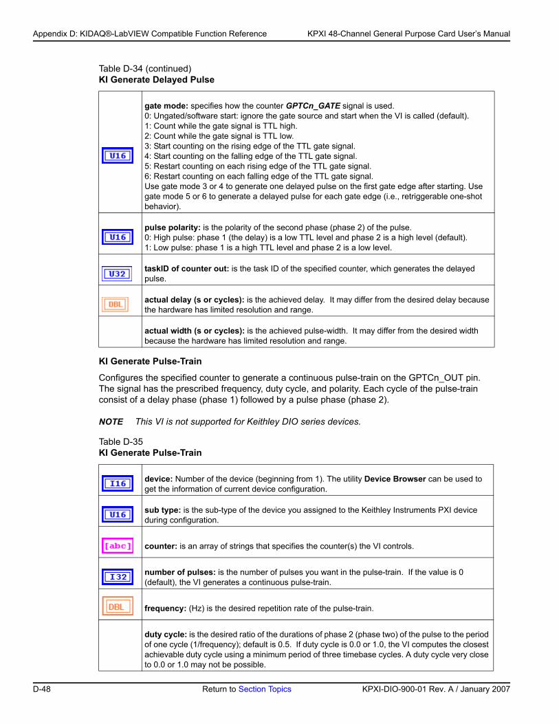
Appendix D: KIDAQ®-LabVIEW Compatible Function Reference KPXI 48-Channel General Purpose Card User’s Manual
KI Generate Pulse-Train
Configures the specified counter to generate a continuous pulse-train on the GPTCn_OUT pin. The signal has the prescribed frequency, duty cycle, and polarity. Each cycle of the pulse-train consist of a delay phase (phase 1) followed by a pulse phase (phase 2).
NOTE This VI is not supported for Keithley DIO series devices.
gate mode: specifies how the counter GPTCn_GATE signal is used. 0: Ungated/software start: ignore the gate source and start when the VI is called (default).1: Count while the gate signal is TTL high.2: Count while the gate signal is TTL low.3: Start counting on the rising edge of the TTL gate signal.4: Start counting on the falling edge of the TTL gate signal.5: Restart counting on each rising edge of the TTL gate signal.6: Restart counting on each falling edge of the TTL gate signal.Use gate mode 3 or 4 to generate one delayed pulse on the first gate edge after starting. Use gate mode 5 or 6 to generate a delayed pulse for each gate edge (i.e., retriggerable one-shot behavior).
pulse polarity: is the polarity of the second phase (phase 2) of the pulse.0: High pulse: phase 1 (the delay) is a low TTL level and phase 2 is a high level (default).1: Low pulse: phase 1 is a high TTL level and phase 2 is a low level.
taskID of counter out: is the task ID of the specified counter, which generates the delayed pulse.
actual delay (s or cycles): is the achieved delay. It may differ from the desired delay because the hardware has limited resolution and range.
actual width (s or cycles): is the achieved pulse-width. It may differ from the desired width because the hardware has limited resolution and range.
Table D-35 KI Generate Pulse-Train
device: Number of the device (beginning from 1). The utility Device Browser can be used to get the information of current device configuration.
sub type: is the sub-type of the device you assigned to the Keithley Instruments PXI device during configuration.
counter: is an array of strings that specifies the counter(s) the VI controls.
number of pulses: is the number of pulses you want in the pulse-train. If the value is 0 (default), the VI generates a continuous pulse-train.
frequency: (Hz) is the desired repetition rate of the pulse-train.
duty cycle: is the desired ratio of the durations of phase 2 (phase two) of the pulse to the period of one cycle (1/frequency); default is 0.5. If duty cycle is 0.0 or 1.0, the VI computes the closest achievable duty cycle using a minimum period of three timebase cycles. A duty cycle very close to 0.0 or 1.0 may not be possible.
Table D-34 (continued)KI Generate Delayed Pulse
D-48 Return to Section Topics KPXI-DIO-900-01 Rev. A / January 2007
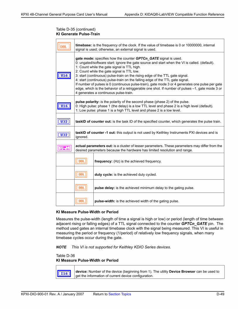
KP
KPXI 48-Channel General Purpose Card User’s Manual Appendix D: KIDAQ®-LabVIEW Compatible Function Reference
KI Measure Pulse-Width or Period
Measures the pulse-width (length of time a signal is high or low) or period (length of time between adjacent rising or falling edges) of a TTL signal connected to the counter GPTCn_GATE pin. The method used gates an internal timebase clock with the signal being measured. This VI is useful in measuring the period or frequency (1/period) of relatively low frequency signals, when many timebase cycles occur during the gate.
NOTE This VI is not supported for Keithley KDIO Series devices.
timebase: is the frequency of the clock. If the value of timebase is 0 or 10000000, internal signal is used; otherwise, an external signal is used.
gate mode: specifies how the counter GPTCn_GATE signal is used. 0: ungated/software start: ignore the gate source and start when the VI is called. (default).1: Count while the gate signal is TTL high.2: Count while the gate signal is TTL low.3: start (continuous) pulse-train on the rising edge of the TTL gate signal.4: start (continuous) pulse-train on the falling edge of the TTL gate signal.If number of pulses is 0 (continuous pulse-train), gate mode 3 or 4 generates one pulse per gate edge, which is the behavior of a retriggerable one shot. If number of pulses –1, gate mode 3 or 4 generates a continuous pulse-train.
pulse polarity: is the polarity of the second phase (phase 2) of the pulse.0: High pulse: phase 1 (the delay) is a low TTL level and phase 2 is a high level (default).1: Low pulse: phase 1 is a high TTL level and phase 2 is a low level.
taskID of counter out: is the task ID of the specified counter, which generates the pulse train.
taskID of counter -1 out: this output is not used by Keithley Instruments PXI devices and is ignored.
actual parameters out: is a cluster of lesser parameters. These parameters may differ from the desired parameters because the hardware has limited resolution and range.
frequency: (Hz) is the achieved frequency.
duty cycle: is the achieved duty cycled.
pulse delay: is the achieved minimum delay to the gating pulse.
pulse-width: is the achieved width of the gating pulse.
Table D-36 KI Measure Pulse-Width or Period
device: Number of the device (beginning from 1). The utility Device Browser can be used to get the information of current device configuration.
Table D-35 (continued)KI Generate Pulse-Train
XI-DIO-900-01 Rev. A / January 2007 Return to Section Topics D-49
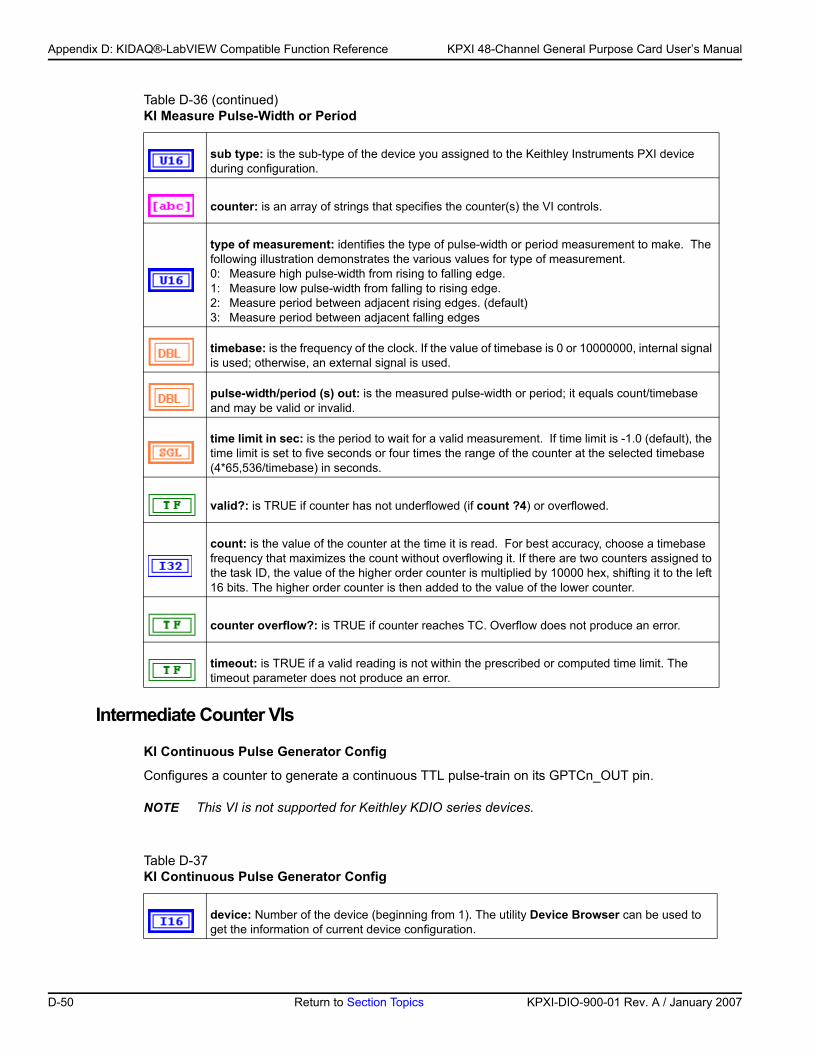
Appendix D: KIDAQ®-LabVIEW Compatible Function Reference KPXI 48-Channel General Purpose Card User’s Manual
Intermediate Counter VIs
KI Continuous Pulse Generator Config
Configures a counter to generate a continuous TTL pulse-train on its GPTCn_OUT pin.
NOTE This VI is not supported for Keithley KDIO series devices.
sub type: is the sub-type of the device you assigned to the Keithley Instruments PXI device during configuration.
counter: is an array of strings that specifies the counter(s) the VI controls.
type of measurement: identifies the type of pulse-width or period measurement to make. The following illustration demonstrates the various values for type of measurement.0: Measure high pulse-width from rising to falling edge.1: Measure low pulse-width from falling to rising edge.2: Measure period between adjacent rising edges. (default)3: Measure period between adjacent falling edges
timebase: is the frequency of the clock. If the value of timebase is 0 or 10000000, internal signal is used; otherwise, an external signal is used.
pulse-width/period (s) out: is the measured pulse-width or period; it equals count/timebase and may be valid or invalid.
time limit in sec: is the period to wait for a valid measurement. If time limit is -1.0 (default), the time limit is set to five seconds or four times the range of the counter at the selected timebase (4*65,536/timebase) in seconds.
valid?: is TRUE if counter has not underflowed (if count ?4) or overflowed.
count: is the value of the counter at the time it is read. For best accuracy, choose a timebase frequency that maximizes the count without overflowing it. If there are two counters assigned to the task ID, the value of the higher order counter is multiplied by 10000 hex, shifting it to the left 16 bits. The higher order counter is then added to the value of the lower counter.
counter overflow?: is TRUE if counter reaches TC. Overflow does not produce an error.
timeout: is TRUE if a valid reading is not within the prescribed or computed time limit. The timeout parameter does not produce an error.
Table D-37 KI Continuous Pulse Generator Config
device: Number of the device (beginning from 1). The utility Device Browser can be used to get the information of current device configuration.
Table D-36 (continued)KI Measure Pulse-Width or Period
D-50 Return to Section Topics KPXI-DIO-900-01 Rev. A / January 2007
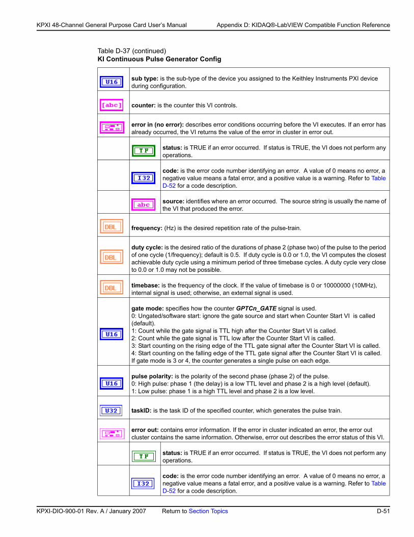
KP
KPXI 48-Channel General Purpose Card User’s Manual Appendix D: KIDAQ®-LabVIEW Compatible Function Reference
sub type: is the sub-type of the device you assigned to the Keithley Instruments PXI device during configuration.
counter: is the counter this VI controls.
error in (no error): describes error conditions occurring before the VI executes. If an error has already occurred, the VI returns the value of the error in cluster in error out.
status: is TRUE if an error occurred. If status is TRUE, the VI does not perform any operations.
code: is the error code number identifying an error. A value of 0 means no error, a negative value means a fatal error, and a positive value is a warning. Refer to Table D-52 for a code description.
source: identifies where an error occurred. The source string is usually the name of the VI that produced the error.
frequency: (Hz) is the desired repetition rate of the pulse-train.
duty cycle: is the desired ratio of the durations of phase 2 (phase two) of the pulse to the period of one cycle (1/frequency); default is 0.5. If duty cycle is 0.0 or 1.0, the VI computes the closest achievable duty cycle using a minimum period of three timebase cycles. A duty cycle very close to 0.0 or 1.0 may not be possible.
timebase: is the frequency of the clock. If the value of timebase is 0 or 10000000 (10MHz), internal signal is used; otherwise, an external signal is used.
gate mode: specifies how the counter GPTCn_GATE signal is used. 0: Ungated/software start: ignore the gate source and start when Counter Start VI is called (default).1: Count while the gate signal is TTL high after the Counter Start VI is called.2: Count while the gate signal is TTL low after the Counter Start VI is called.3: Start counting on the rising edge of the TTL gate signal after the Counter Start VI is called.4: Start counting on the falling edge of the TTL gate signal after the Counter Start VI is called.If gate mode is 3 or 4, the counter generates a single pulse on each edge.
pulse polarity: is the polarity of the second phase (phase 2) of the pulse. 0: High pulse: phase 1 (the delay) is a low TTL level and phase 2 is a high level (default).1: Low pulse: phase 1 is a high TTL level and phase 2 is a low level.
taskID: is the task ID of the specified counter, which generates the pulse train.
error out: contains error information. If the error in cluster indicated an error, the error out cluster contains the same information. Otherwise, error out describes the error status of this VI.
status: is TRUE if an error occurred. If status is TRUE, the VI does not perform any operations.
code: is the error code number identifying an error. A value of 0 means no error, a negative value means a fatal error, and a positive value is a warning. Refer to Table D-52 for a code description.
Table D-37 (continued)KI Continuous Pulse Generator Config
XI-DIO-900-01 Rev. A / January 2007 Return to Section Topics D-51
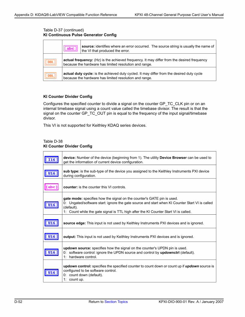
Appendix D: KIDAQ®-LabVIEW Compatible Function Reference KPXI 48-Channel General Purpose Card User’s Manual
KI Counter Divider Config
Configures the specified counter to divide a signal on the counter GP_TC_CLK pin or on an internal timebase signal using a count value called the timebase divisor. The result is that the signal on the counter GP_TC_OUT pin is equal to the frequency of the input signal/timebase divisor.
This VI is not supported for Keithley KDAQ series devices.
source: identifies where an error occurred. The source string is usually the name of the VI that produced the error.
actual frequency: (Hz) is the achieved frequency. It may differ from the desired frequency because the hardware has limited resolution and range.
actual duty cycle: is the achieved duty cycled. It may differ from the desired duty cycle because the hardware has limited resolution and range.
Table D-38 KI Counter Divider Config
device: Number of the device (beginning from 1). The utility Device Browser can be used to get the information of current device configuration.
sub type: is the sub-type of the device you assigned to the Keithley Instruments PXI device during configuration.
counter: is the counter this VI controls.
gate mode: specifies how the signal on the counter's GATE pin is used.0: Ungated/software start: ignore the gate source and start when KI Counter Start VI is called (default).1: Count while the gate signal is TTL high after the KI Counter Start VI is called.
source edge: This input is not used by Keithley Instruments PXI devices and is ignored.
output: This input is not used by Keithley Instruments PXI devices and is ignored.
updown source: specifies how the signal on the counter's UPDN pin is used.0: software control: ignore the UPDN source and control by updownctrl (default).1: hardware control.
updown control: specifies the specified counter to count down or count up if updown source is configured to be software control.0: count down (default).1: count up.
Table D-37 (continued)KI Continuous Pulse Generator Config
D-52 Return to Section Topics KPXI-DIO-900-01 Rev. A / January 2007
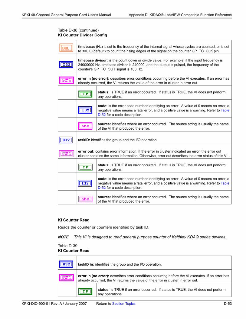
KP
KPXI 48-Channel General Purpose Card User’s Manual Appendix D: KIDAQ®-LabVIEW Compatible Function Reference
KI Counter Read
Reads the counter or counters identified by task ID.
NOTE This VI is designed to read general purpose counter of Keithley KDAQ series devices.
timebase: (Hz) is set to the frequency of the internal signal whose cycles are counted, or is set to <=0.0 (default) to count the rising edges of the signal on the counter GP_TC_CLK pin.
timebase divisor: is the count down or divide value. For example, if the input frequency is 24000000 Hz, timebase divisor is 240000, and the output is pulsed, the frequency of the counter's GP_TC_OUT signal is 100 Hz.
error in (no error): describes error conditions occurring before the VI executes. If an error has already occurred, the VI returns the value of the error in cluster in error out.
status: is TRUE if an error occurred. If status is TRUE, the VI does not perform any operations.
code: is the error code number identifying an error. A value of 0 means no error, a negative value means a fatal error, and a positive value is a warning. Refer to Table D-52 for a code description.
source: identifies where an error occurred. The source string is usually the name of the VI that produced the error.
taskID: identifies the group and the I/O operation.
error out: contains error information. If the error in cluster indicated an error, the error out cluster contains the same information. Otherwise, error out describes the error status of this VI.
status: is TRUE if an error occurred. If status is TRUE, the VI does not perform any operations.
code: is the error code number identifying an error. A value of 0 means no error, a negative value means a fatal error, and a positive value is a warning. Refer to Table D-52 for a code description.
source: identifies where an error occurred. The source string is usually the name of the VI that produced the error.
Table D-39 KI Counter Read
taskID in: identifies the group and the I/O operation.
error in (no error): describes error conditions occurring before the VI executes. If an error has already occurred, the VI returns the value of the error in cluster in error out.
status: is TRUE if an error occurred. If status is TRUE, the VI does not perform any operations.
Table D-38 (continued)KI Counter Divider Config
XI-DIO-900-01 Rev. A / January 2007 Return to Section Topics D-53
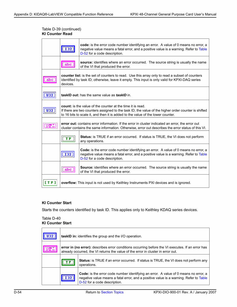
Appendix D: KIDAQ®-LabVIEW Compatible Function Reference KPXI 48-Channel General Purpose Card User’s Manual
KI Counter Start
Starts the counters identified by task ID. This applies only to Keithley KDAQ series devices.
code: is the error code number identifying an error. A value of 0 means no error, a negative value means a fatal error, and a positive value is a warning. Refer to Table D-52 for a code description.
source: identifies where an error occurred. The source string is usually the name of the VI that produced the error.
counter list: is the set of counters to read. Use this array only to read a subset of counters identified by task ID; otherwise, leave it empty. This input is only valid for KPXI-DAQ series devices.
taskID out: has the same value as taskID in.
count: is the value of the counter at the time it is read.If there are two counters assigned to the task ID, the value of the higher order counter is shifted to 16 bits to scale it, and then it is added to the value of the lower counter.
error out: contains error information. If the error in cluster indicated an error, the error out cluster contains the same information. Otherwise, error out describes the error status of this VI.
Status: is TRUE if an error occurred. If status is TRUE, the VI does not perform any operations.
Code: is the error code number identifying an error. A value of 0 means no error, a negative value means a fatal error, and a positive value is a warning. Refer to Table D-52 for a code description.
Source: identifies where an error occurred. The source string is usually the name of the VI that produced the error.
overflow: This input is not used by Keithley Instruments PXI devices and is ignored.
Table D-40 KI Counter Start
taskID in: identifies the group and the I/O operation.
error in (no error): describes error conditions occurring before the VI executes. If an error has already occurred, the VI returns the value of the error in cluster in error out.
Status: is TRUE if an error occurred. If status is TRUE, the VI does not perform any operations.
Code: is the error code number identifying an error. A value of 0 means no error, a negative value means a fatal error, and a positive value is a warning. Refer to Table D-52 for a code description.
Table D-39 (continued)KI Counter Read
D-54 Return to Section Topics KPXI-DIO-900-01 Rev. A / January 2007
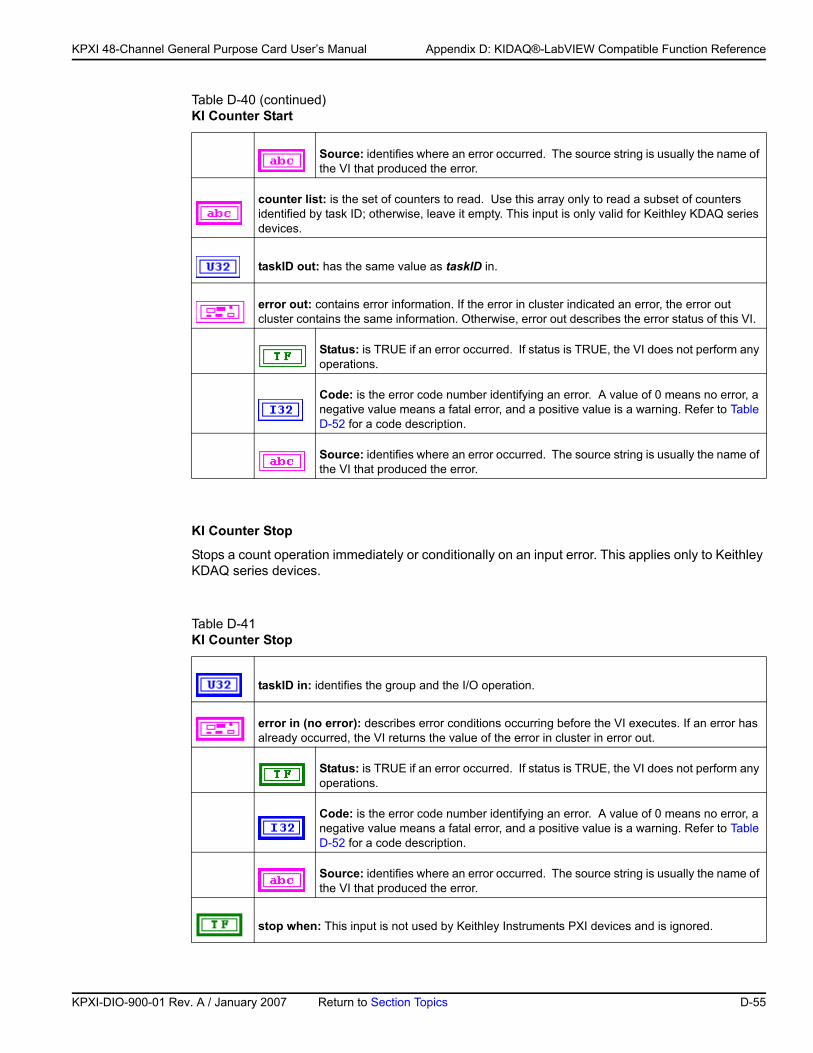
KP
KPXI 48-Channel General Purpose Card User’s Manual Appendix D: KIDAQ®-LabVIEW Compatible Function Reference
KI Counter Stop
Stops a count operation immediately or conditionally on an input error. This applies only to Keithley KDAQ series devices.
Source: identifies where an error occurred. The source string is usually the name of the VI that produced the error.
counter list: is the set of counters to read. Use this array only to read a subset of counters identified by task ID; otherwise, leave it empty. This input is only valid for Keithley KDAQ series devices.
taskID out: has the same value as taskID in.
error out: contains error information. If the error in cluster indicated an error, the error out cluster contains the same information. Otherwise, error out describes the error status of this VI.
Status: is TRUE if an error occurred. If status is TRUE, the VI does not perform any operations.
Code: is the error code number identifying an error. A value of 0 means no error, a negative value means a fatal error, and a positive value is a warning. Refer to Table D-52 for a code description.
Source: identifies where an error occurred. The source string is usually the name of the VI that produced the error.
Table D-41 KI Counter Stop
taskID in: identifies the group and the I/O operation.
error in (no error): describes error conditions occurring before the VI executes. If an error has already occurred, the VI returns the value of the error in cluster in error out.
Status: is TRUE if an error occurred. If status is TRUE, the VI does not perform any operations.
Code: is the error code number identifying an error. A value of 0 means no error, a negative value means a fatal error, and a positive value is a warning. Refer to Table D-52 for a code description.
Source: identifies where an error occurred. The source string is usually the name of the VI that produced the error.
stop when: This input is not used by Keithley Instruments PXI devices and is ignored.
Table D-40 (continued)KI Counter Start
XI-DIO-900-01 Rev. A / January 2007 Return to Section Topics D-55
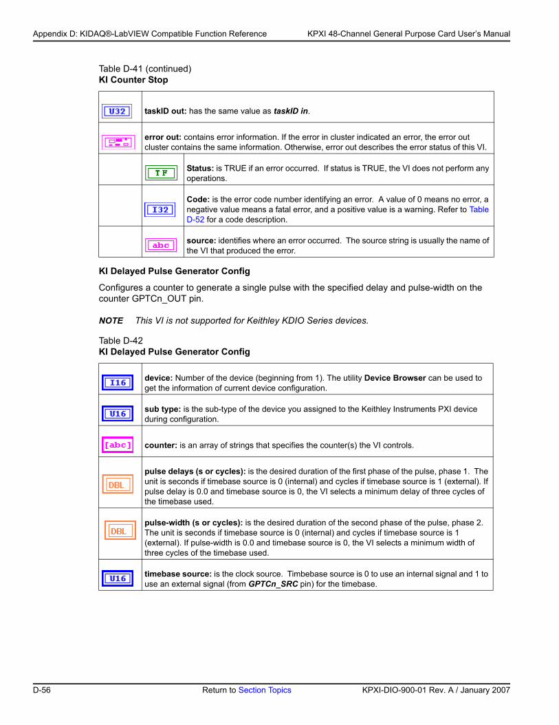
Appendix D: KIDAQ®-LabVIEW Compatible Function Reference KPXI 48-Channel General Purpose Card User’s Manual
KI Delayed Pulse Generator Config
Configures a counter to generate a single pulse with the specified delay and pulse-width on the counter GPTCn_OUT pin.
NOTE This VI is not supported for Keithley KDIO Series devices.
taskID out: has the same value as taskID in.
error out: contains error information. If the error in cluster indicated an error, the error out cluster contains the same information. Otherwise, error out describes the error status of this VI.
Status: is TRUE if an error occurred. If status is TRUE, the VI does not perform any operations.
Code: is the error code number identifying an error. A value of 0 means no error, a negative value means a fatal error, and a positive value is a warning. Refer to Table D-52 for a code description.
source: identifies where an error occurred. The source string is usually the name of the VI that produced the error.
Table D-42 KI Delayed Pulse Generator Config
device: Number of the device (beginning from 1). The utility Device Browser can be used to get the information of current device configuration.
sub type: is the sub-type of the device you assigned to the Keithley Instruments PXI device during configuration.
counter: is an array of strings that specifies the counter(s) the VI controls.
pulse delays (s or cycles): is the desired duration of the first phase of the pulse, phase 1. The unit is seconds if timebase source is 0 (internal) and cycles if timebase source is 1 (external). If pulse delay is 0.0 and timebase source is 0, the VI selects a minimum delay of three cycles of the timebase used.
pulse-width (s or cycles): is the desired duration of the second phase of the pulse, phase 2. The unit is seconds if timebase source is 0 (internal) and cycles if timebase source is 1 (external). If pulse-width is 0.0 and timebase source is 0, the VI selects a minimum width of three cycles of the timebase used.
timebase source: is the clock source. Timbebase source is 0 to use an internal signal and 1 to use an external signal (from GPTCn_SRC pin) for the timebase.
Table D-41 (continued)KI Counter Stop
D-56 Return to Section Topics KPXI-DIO-900-01 Rev. A / January 2007
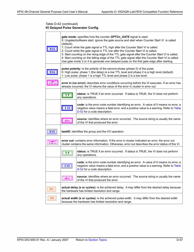
KP
KPXI 48-Channel General Purpose Card User’s Manual Appendix D: KIDAQ®-LabVIEW Compatible Function Reference
gate mode: specifies how the counter GPTCn_GATE signal is used. 0: Ungated/software start: ignore the gate source and start when Counter Start VI is called (default)..1: Count while the gate signal is TTL high after the Counter Start VI is called.2: Count while the gate signal is TTL low after the Counter Start VI is called.3: Start counting on the rising edge of the TTL gate signal after the Counter Start VI is called.4: Start counting on the falling edge of the TTL gate signal after the Counter Start VI is called.Use gate mode 3 or 4 to generate one delayed pulse on the first gate edge after starting.
pulse polarity: is the polarity of the second phase (phase 2) of the pulse. 0: High pulse: phase 1 (the delay) is a low TTL level and phase 2 is a high level (default).1: Low pulse: phase 1 is a high TTL level and phase 2 is a low level.
error in (no error): describes error conditions occurring before the VI executes. If an error has already occurred, the VI returns the value of the error in cluster in error out.
status: is TRUE if an error occurred. If status is TRUE, the VI does not perform any operations.
code: is the error code number identifying an error. A value of 0 means no error, a negative value means a fatal error, and a positive value is a warning. Refer to Table D-52 for a code description.
source: identifies where an error occurred. The source string is usually the name of the VI that produced the error.
taskID: identifies the group and the I/O operation.
error out: contains error information. If the error in cluster indicated an error, the error out cluster contains the same information. Otherwise, error out describes the error status of this VI.
status: is TRUE if an error occurred. If status is TRUE, the VI does not perform any operations.
code: is the error code number identifying an error. A value of 0 means no error, a negative value means a fatal error, and a positive value is a warning. Refer to Table D-52 for a code description.
source: identifies where an error occurred. The source string is usually the name of the VI that produced the error.
actual delay (s or cycles): is the achieved delay. It may differ from the desired delay because the hardware has limited resolution and range.
actual width (s or cycles): is the achieved pulse-width. It may differ from the desired width because the hardware has limited resolution and range.
Table D-42 (continued)KI Delayed Pulse Generator Config
XI-DIO-900-01 Rev. A / January 2007 Return to Section Topics D-57
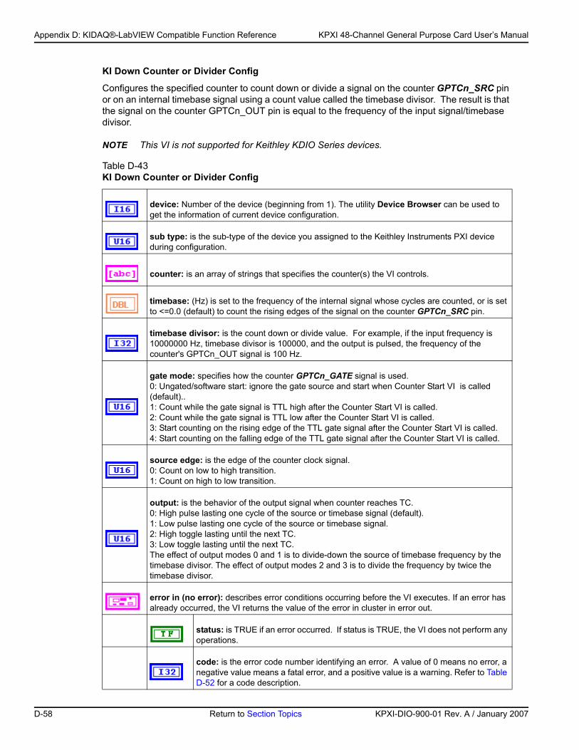
Appendix D: KIDAQ®-LabVIEW Compatible Function Reference KPXI 48-Channel General Purpose Card User’s Manual
KI Down Counter or Divider Config
Configures the specified counter to count down or divide a signal on the counter GPTCn_SRC pin or on an internal timebase signal using a count value called the timebase divisor. The result is that the signal on the counter GPTCn_OUT pin is equal to the frequency of the input signal/timebase divisor.
NOTE This VI is not supported for Keithley KDIO Series devices.
Table D-43 KI Down Counter or Divider Config
device: Number of the device (beginning from 1). The utility Device Browser can be used to get the information of current device configuration.
sub type: is the sub-type of the device you assigned to the Keithley Instruments PXI device during configuration.
counter: is an array of strings that specifies the counter(s) the VI controls.
timebase: (Hz) is set to the frequency of the internal signal whose cycles are counted, or is set to <=0.0 (default) to count the rising edges of the signal on the counter GPTCn_SRC pin.
timebase divisor: is the count down or divide value. For example, if the input frequency is 10000000 Hz, timebase divisor is 100000, and the output is pulsed, the frequency of the counter's GPTCn_OUT signal is 100 Hz.
gate mode: specifies how the counter GPTCn_GATE signal is used. 0: Ungated/software start: ignore the gate source and start when Counter Start VI is called (default)..1: Count while the gate signal is TTL high after the Counter Start VI is called.2: Count while the gate signal is TTL low after the Counter Start VI is called.3: Start counting on the rising edge of the TTL gate signal after the Counter Start VI is called.4: Start counting on the falling edge of the TTL gate signal after the Counter Start VI is called.
source edge: is the edge of the counter clock signal.0: Count on low to high transition.1: Count on high to low transition.
output: is the behavior of the output signal when counter reaches TC. 0: High pulse lasting one cycle of the source or timebase signal (default).1: Low pulse lasting one cycle of the source or timebase signal.2: High toggle lasting until the next TC.3: Low toggle lasting until the next TC.The effect of output modes 0 and 1 is to divide-down the source of timebase frequency by the timebase divisor. The effect of output modes 2 and 3 is to divide the frequency by twice the timebase divisor.
error in (no error): describes error conditions occurring before the VI executes. If an error has already occurred, the VI returns the value of the error in cluster in error out.
status: is TRUE if an error occurred. If status is TRUE, the VI does not perform any operations.
code: is the error code number identifying an error. A value of 0 means no error, a negative value means a fatal error, and a positive value is a warning. Refer to Table D-52 for a code description.
D-58 Return to Section Topics KPXI-DIO-900-01 Rev. A / January 2007
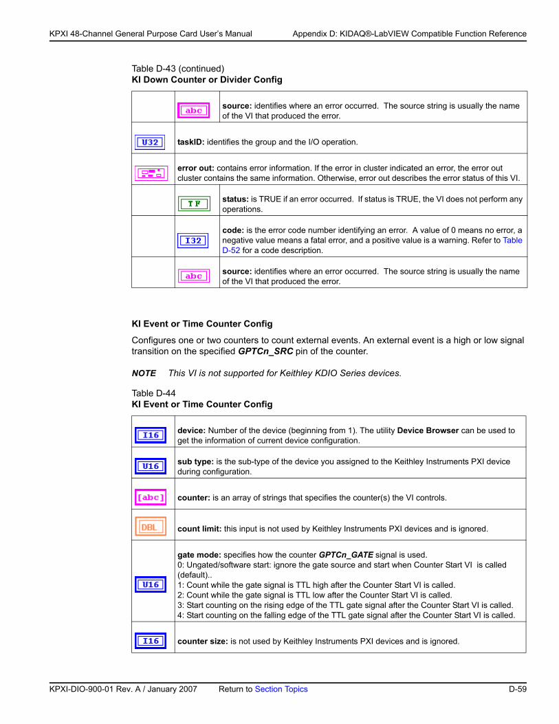
KP
KPXI 48-Channel General Purpose Card User’s Manual Appendix D: KIDAQ®-LabVIEW Compatible Function Reference
KI Event or Time Counter Config
Configures one or two counters to count external events. An external event is a high or low signal transition on the specified GPTCn_SRC pin of the counter.
NOTE This VI is not supported for Keithley KDIO Series devices.
source: identifies where an error occurred. The source string is usually the name of the VI that produced the error.
taskID: identifies the group and the I/O operation.
error out: contains error information. If the error in cluster indicated an error, the error out cluster contains the same information. Otherwise, error out describes the error status of this VI.
status: is TRUE if an error occurred. If status is TRUE, the VI does not perform any operations.
code: is the error code number identifying an error. A value of 0 means no error, a negative value means a fatal error, and a positive value is a warning. Refer to Table D-52 for a code description.
source: identifies where an error occurred. The source string is usually the name of the VI that produced the error.
Table D-44 KI Event or Time Counter Config
device: Number of the device (beginning from 1). The utility Device Browser can be used to get the information of current device configuration.
sub type: is the sub-type of the device you assigned to the Keithley Instruments PXI device during configuration.
counter: is an array of strings that specifies the counter(s) the VI controls.
count limit: this input is not used by Keithley Instruments PXI devices and is ignored.
gate mode: specifies how the counter GPTCn_GATE signal is used. 0: Ungated/software start: ignore the gate source and start when Counter Start VI is called (default)..1: Count while the gate signal is TTL high after the Counter Start VI is called.2: Count while the gate signal is TTL low after the Counter Start VI is called.3: Start counting on the rising edge of the TTL gate signal after the Counter Start VI is called.4: Start counting on the falling edge of the TTL gate signal after the Counter Start VI is called.
counter size: is not used by Keithley Instruments PXI devices and is ignored.
Table D-43 (continued)KI Down Counter or Divider Config
XI-DIO-900-01 Rev. A / January 2007 Return to Section Topics D-59
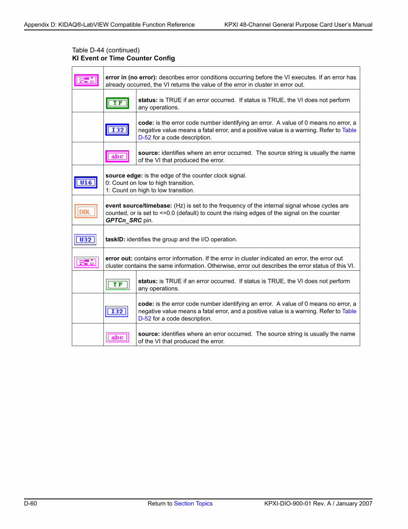
Appendix D: KIDAQ®-LabVIEW Compatible Function Reference KPXI 48-Channel General Purpose Card User’s Manual
error in (no error): describes error conditions occurring before the VI executes. If an error has already occurred, the VI returns the value of the error in cluster in error out.
status: is TRUE if an error occurred. If status is TRUE, the VI does not perform any operations.
code: is the error code number identifying an error. A value of 0 means no error, a negative value means a fatal error, and a positive value is a warning. Refer to Table D-52 for a code description.
source: identifies where an error occurred. The source string is usually the name of the VI that produced the error.
source edge: is the edge of the counter clock signal.0: Count on low to high transition.1: Count on high to low transition.
event source/timebase: (Hz) is set to the frequency of the internal signal whose cycles are counted, or is set to <=0.0 (default) to count the rising edges of the signal on the counter GPTCn_SRC pin.
taskID: identifies the group and the I/O operation.
error out: contains error information. If the error in cluster indicated an error, the error out cluster contains the same information. Otherwise, error out describes the error status of this VI.
status: is TRUE if an error occurred. If status is TRUE, the VI does not perform any operations.
code: is the error code number identifying an error. A value of 0 means no error, a negative value means a fatal error, and a positive value is a warning. Refer to Table D-52 for a code description.
source: identifies where an error occurred. The source string is usually the name of the VI that produced the error.
Table D-44 (continued)KI Event or Time Counter Config
D-60 Return to Section Topics KPXI-DIO-900-01 Rev. A / January 2007
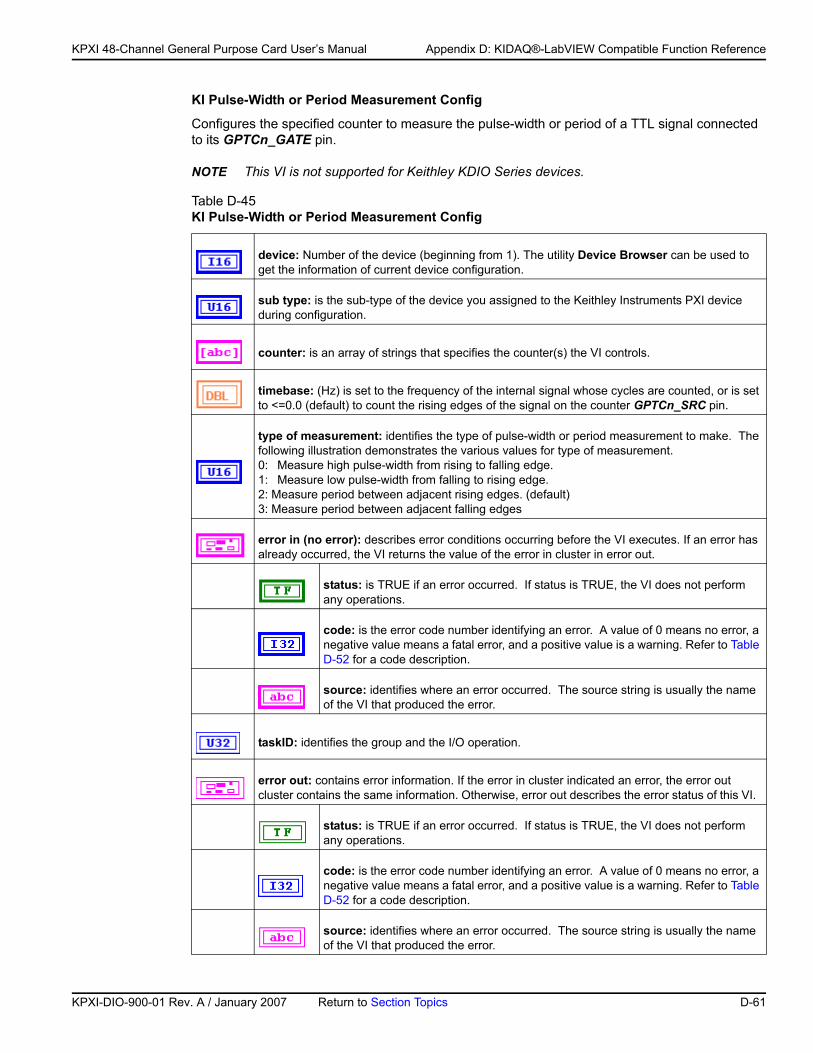
KP
KPXI 48-Channel General Purpose Card User’s Manual Appendix D: KIDAQ®-LabVIEW Compatible Function Reference
KI Pulse-Width or Period Measurement Config
Configures the specified counter to measure the pulse-width or period of a TTL signal connected to its GPTCn_GATE pin.
NOTE This VI is not supported for Keithley KDIO Series devices.
Table D-45 KI Pulse-Width or Period Measurement Config
device: Number of the device (beginning from 1). The utility Device Browser can be used to get the information of current device configuration.
sub type: is the sub-type of the device you assigned to the Keithley Instruments PXI device during configuration.
counter: is an array of strings that specifies the counter(s) the VI controls.
timebase: (Hz) is set to the frequency of the internal signal whose cycles are counted, or is set to <=0.0 (default) to count the rising edges of the signal on the counter GPTCn_SRC pin.
type of measurement: identifies the type of pulse-width or period measurement to make. The following illustration demonstrates the various values for type of measurement.0: Measure high pulse-width from rising to falling edge.1: Measure low pulse-width from falling to rising edge.2: Measure period between adjacent rising edges. (default)3: Measure period between adjacent falling edges
error in (no error): describes error conditions occurring before the VI executes. If an error has already occurred, the VI returns the value of the error in cluster in error out.
status: is TRUE if an error occurred. If status is TRUE, the VI does not perform any operations.
code: is the error code number identifying an error. A value of 0 means no error, a negative value means a fatal error, and a positive value is a warning. Refer to Table D-52 for a code description.
source: identifies where an error occurred. The source string is usually the name of the VI that produced the error.
taskID: identifies the group and the I/O operation.
error out: contains error information. If the error in cluster indicated an error, the error out cluster contains the same information. Otherwise, error out describes the error status of this VI.
status: is TRUE if an error occurred. If status is TRUE, the VI does not perform any operations.
code: is the error code number identifying an error. A value of 0 means no error, a negative value means a fatal error, and a positive value is a warning. Refer to Table D-52 for a code description.
source: identifies where an error occurred. The source string is usually the name of the VI that produced the error.
XI-DIO-900-01 Rev. A / January 2007 Return to Section Topics D-61
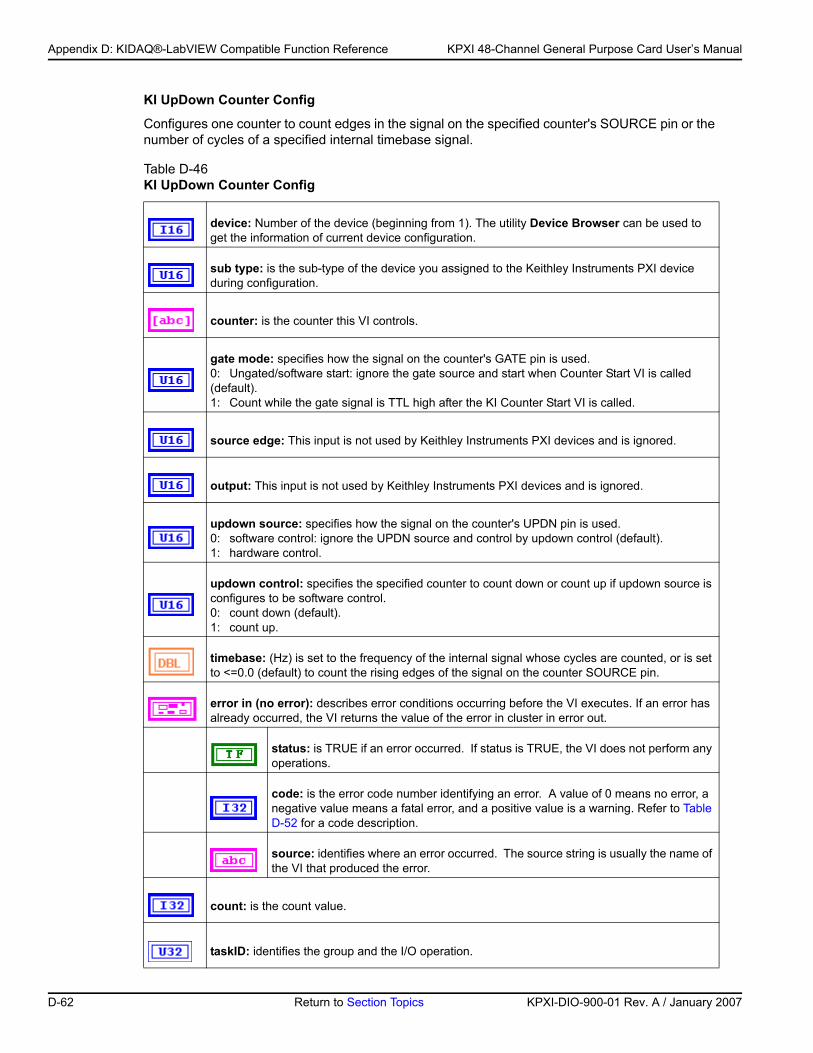
Appendix D: KIDAQ®-LabVIEW Compatible Function Reference KPXI 48-Channel General Purpose Card User’s Manual
KI UpDown Counter Config
Configures one counter to count edges in the signal on the specified counter's SOURCE pin or the number of cycles of a specified internal timebase signal.
Table D-46 KI UpDown Counter Config
device: Number of the device (beginning from 1). The utility Device Browser can be used to get the information of current device configuration.
sub type: is the sub-type of the device you assigned to the Keithley Instruments PXI device during configuration.
counter: is the counter this VI controls.
gate mode: specifies how the signal on the counter's GATE pin is used.0: Ungated/software start: ignore the gate source and start when Counter Start VI is called (default).1: Count while the gate signal is TTL high after the KI Counter Start VI is called.
source edge: This input is not used by Keithley Instruments PXI devices and is ignored.
output: This input is not used by Keithley Instruments PXI devices and is ignored.
updown source: specifies how the signal on the counter's UPDN pin is used.0: software control: ignore the UPDN source and control by updown control (default).1: hardware control.
updown control: specifies the specified counter to count down or count up if updown source is configures to be software control.0: count down (default).1: count up.
timebase: (Hz) is set to the frequency of the internal signal whose cycles are counted, or is set to <=0.0 (default) to count the rising edges of the signal on the counter SOURCE pin.
error in (no error): describes error conditions occurring before the VI executes. If an error has already occurred, the VI returns the value of the error in cluster in error out.
status: is TRUE if an error occurred. If status is TRUE, the VI does not perform any operations.
code: is the error code number identifying an error. A value of 0 means no error, a negative value means a fatal error, and a positive value is a warning. Refer to Table D-52 for a code description.
source: identifies where an error occurred. The source string is usually the name of the VI that produced the error.
count: is the count value.
taskID: identifies the group and the I/O operation.
D-62 Return to Section Topics KPXI-DIO-900-01 Rev. A / January 2007
KP
KPXI 48-Channel General Purpose Card User’s Manual Appendix D: KIDAQ®-LabVIEW Compatible Function Reference
Advanced Counter VIs
KI ICTR Control
This VI control counters on the Keithley Instruments PXI devices that use 82C54 chip. Control operations include starting, stopping, and setting the state of active acquisitions.
NOTE This VI is not supported for Keithley KDAQ series devices.
error out: contains error information. If the error in cluster indicated an error, the error out cluster contains the same information. Otherwise, error out describes the error status of this VI.
status: is TRUE if an error occurred. If status is TRUE, the VI does not perform any operations.
code: is the error code number identifying an error. A value of 0 means no error, a negative value means a fatal error, and a positive value is a warning. Refer to Table D-52 for a code description.
source: identifies where an error occurred. The source string is usually the name of the VI that produced the error.
Table D-47 KI ICTR Control
device: Number of the device (beginning from 1). The utility Device Browser can be used to get the information of current device configuration.
sub type: is the sub-type of the device you assigned to the Keithley Instruments PXI device during configuration.
counter: is the counter this VI controls.KPXI-DIO-48: 0, 1 or 2
control code: 0: Setup mode 0 – Toggle output from low to high on TC (default). 1: Setup mode 1 – Programmable one-shot.2: Setup mode 2 – Rate generator.3: Setup mode 3 – Square wave rate demerara.4: Setup mode 4 – Software-triggered strobe. 5: Setup mode 5 – Hardware-triggered strobe.6: Read.7: Reset.
Table D-46 (continued)KI UpDown Counter Config
XI-DIO-900-01 Rev. A / January 2007 Return to Section Topics D-63
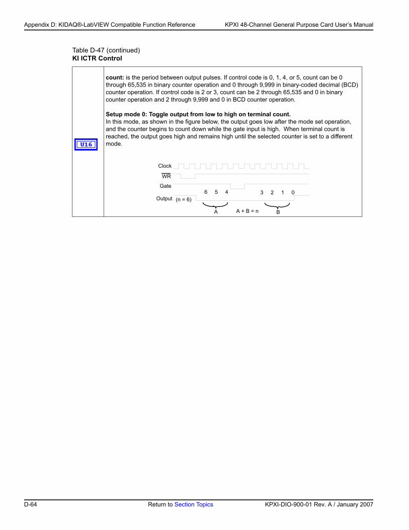
Appendix D: KIDAQ®-LabVIEW Compatible Function Reference KPXI 48-Channel General Purpose Card User’s Manual
count: is the period between output pulses. If control code is 0, 1, 4, or 5, count can be 0 through 65,535 in binary counter operation and 0 through 9,999 in binary-coded decimal (BCD) counter operation. If control code is 2 or 3, count can be 2 through 65,535 and 0 in binary counter operation and 2 through 9,999 and 0 in BCD counter operation.
Setup mode 0: Toggle output from low to high on terminal count. In this mode, as shown in the figure below, the output goes low after the mode set operation, and the counter begins to count down while the gate input is high. When terminal count is reached, the output goes high and remains high until the selected counter is set to a different mode.
Table D-47 (continued)KI ICTR Control
Clock
WR
Gate
Output6 5 4 3 2 1 0
(n = 6)
A BA + B = n
D-64 Return to Section Topics KPXI-DIO-900-01 Rev. A / January 2007
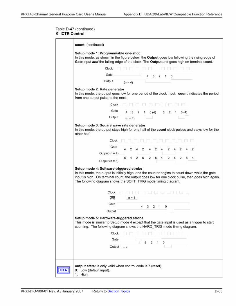
KP
KPXI 48-Channel General Purpose Card User’s Manual Appendix D: KIDAQ®-LabVIEW Compatible Function Reference
count: (continued)
Setup mode 1: Programmable one-shotIn this mode, as shown in the figure below, the Output goes low following the rising edge of Gate input and the falling edge of the clock. The Output and goes high on terminal count.
Setup mode 2: Rate generatorIn this mode, the output goes low for one period of the clock input. count indicates the period from one output pulse to the next.
Setup mode 3: Square wave rate generatorIn this mode, the output stays high for one half of the count clock pulses and stays low for the other half.
Setup mode 4: Software-triggered strobe In this mode, the output is initially high, and the counter begins to count down while the gate input is high. On terminal count, the output goes low for one clock pulse, then goes high again. The following diagram shows the SOFT_TRIG mode timing diagram.
Setup mode 5: Hardware-triggered strobeThis mode is similar to Setup mode 4 except that the gate input is used as a trigger to start counting. The following diagram shows the HARD_TRIG mode timing diagram.
output state: is only valid when control code is 7 (reset). 0: Low (default input).1: High.
Table D-47 (continued)KI ICTR Control
Clock
Gate
Output4 3 2 1 0
(n = 4)
Clock
Gate
Output4 3 2 1 0 (4) 3 2 1 0 (4)
(n = 4)
Clock
Gate
Output (n = 4)4 2 4 2 4 2 4 2 4 2 4 2
Output (n = 5)5 4 2 5 2 5 4 2 5 2 5 4
Clock
WR
Gate
Output4 3 2 1 0
n = 4
Clock
Gate
Output4 3 2 1 0
n = 4
XI-DIO-900-01 Rev. A / January 2007 Return to Section Topics D-65
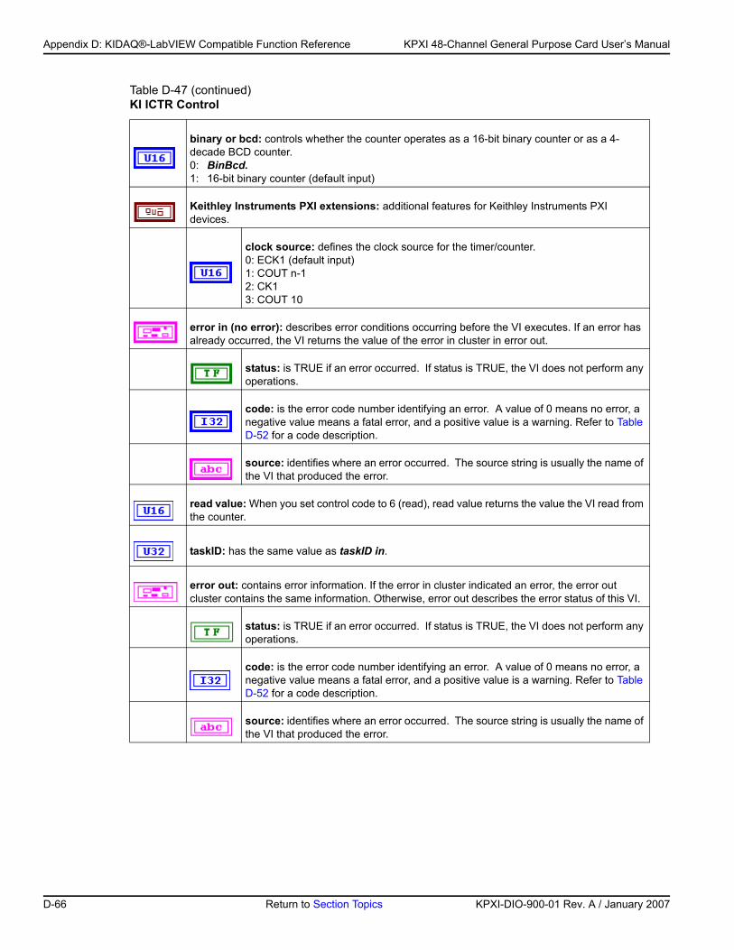
Appendix D: KIDAQ®-LabVIEW Compatible Function Reference KPXI 48-Channel General Purpose Card User’s Manual
binary or bcd: controls whether the counter operates as a 16-bit binary counter or as a 4-decade BCD counter. 0: BinBcd.1: 16-bit binary counter (default input)
Keithley Instruments PXI extensions: additional features for Keithley Instruments PXI devices.
clock source: defines the clock source for the timer/counter.0: ECK1 (default input)1: COUT n-12: CK13: COUT 10
error in (no error): describes error conditions occurring before the VI executes. If an error has already occurred, the VI returns the value of the error in cluster in error out.
status: is TRUE if an error occurred. If status is TRUE, the VI does not perform any operations.
code: is the error code number identifying an error. A value of 0 means no error, a negative value means a fatal error, and a positive value is a warning. Refer to Table D-52 for a code description.
source: identifies where an error occurred. The source string is usually the name of the VI that produced the error.
read value: When you set control code to 6 (read), read value returns the value the VI read from the counter.
taskID: has the same value as taskID in.
error out: contains error information. If the error in cluster indicated an error, the error out cluster contains the same information. Otherwise, error out describes the error status of this VI.
status: is TRUE if an error occurred. If status is TRUE, the VI does not perform any operations.
code: is the error code number identifying an error. A value of 0 means no error, a negative value means a fatal error, and a positive value is a warning. Refer to Table D-52 for a code description.
source: identifies where an error occurred. The source string is usually the name of the VI that produced the error.
Table D-47 (continued)KI ICTR Control
D-66 Return to Section Topics KPXI-DIO-900-01 Rev. A / January 2007
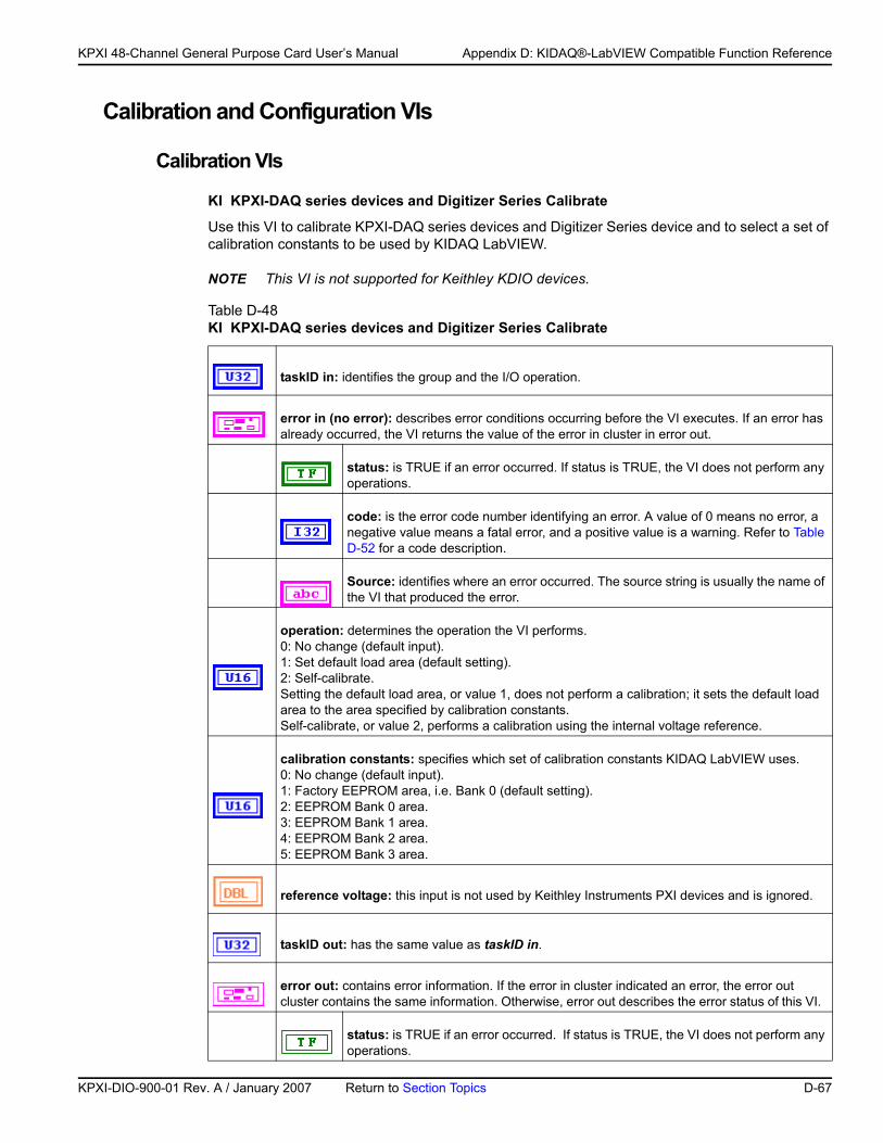
KP
KPXI 48-Channel General Purpose Card User’s Manual Appendix D: KIDAQ®-LabVIEW Compatible Function Reference
Calibration and Configuration VIs
Calibration VIs
KI KPXI-DAQ series devices and Digitizer Series Calibrate
Use this VI to calibrate KPXI-DAQ series devices and Digitizer Series device and to select a set of calibration constants to be used by KIDAQ LabVIEW.
NOTE This VI is not supported for Keithley KDIO devices.
Table D-48 KI KPXI-DAQ series devices and Digitizer Series Calibrate
taskID in: identifies the group and the I/O operation.
error in (no error): describes error conditions occurring before the VI executes. If an error has already occurred, the VI returns the value of the error in cluster in error out.
status: is TRUE if an error occurred. If status is TRUE, the VI does not perform any operations.
code: is the error code number identifying an error. A value of 0 means no error, a negative value means a fatal error, and a positive value is a warning. Refer to Table D-52 for a code description.
Source: identifies where an error occurred. The source string is usually the name of the VI that produced the error.
operation: determines the operation the VI performs. 0: No change (default input).1: Set default load area (default setting).2: Self-calibrate.Setting the default load area, or value 1, does not perform a calibration; it sets the default load area to the area specified by calibration constants.Self-calibrate, or value 2, performs a calibration using the internal voltage reference.
calibration constants: specifies which set of calibration constants KIDAQ LabVIEW uses. 0: No change (default input).1: Factory EEPROM area, i.e. Bank 0 (default setting).2: EEPROM Bank 0 area.3: EEPROM Bank 1 area.4: EEPROM Bank 2 area.5: EEPROM Bank 3 area.
reference voltage: this input is not used by Keithley Instruments PXI devices and is ignored.
taskID out: has the same value as taskID in.
error out: contains error information. If the error in cluster indicated an error, the error out cluster contains the same information. Otherwise, error out describes the error status of this VI.
status: is TRUE if an error occurred. If status is TRUE, the VI does not perform any operations.
XI-DIO-900-01 Rev. A / January 2007 Return to Section Topics D-67
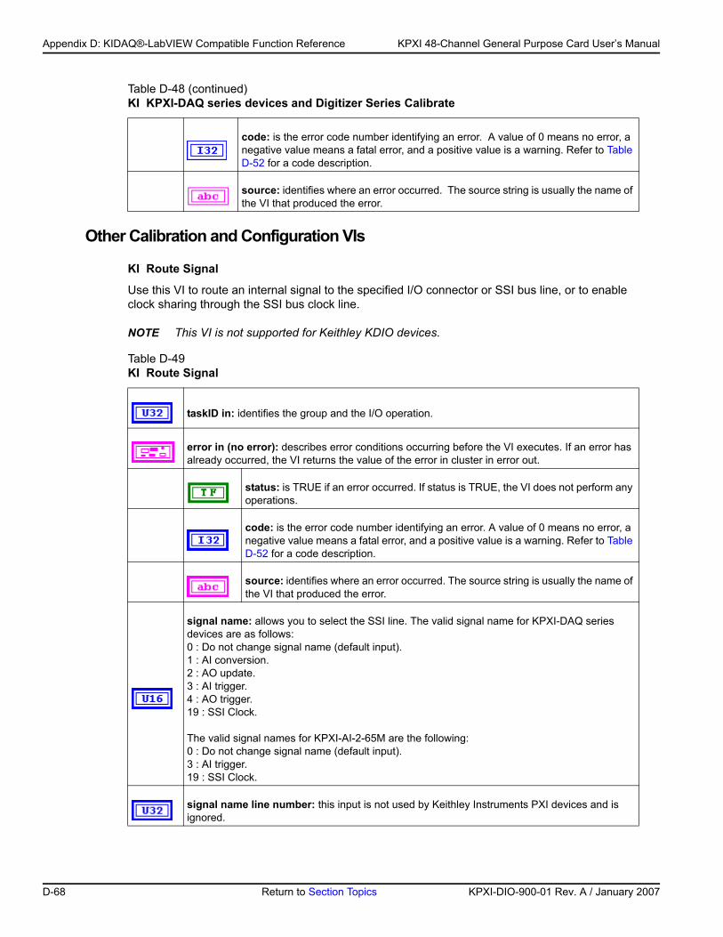
Appendix D: KIDAQ®-LabVIEW Compatible Function Reference KPXI 48-Channel General Purpose Card User’s Manual
Other Calibration and Configuration VIs
KI Route Signal
Use this VI to route an internal signal to the specified I/O connector or SSI bus line, or to enable clock sharing through the SSI bus clock line.
NOTE This VI is not supported for Keithley KDIO devices.
code: is the error code number identifying an error. A value of 0 means no error, a negative value means a fatal error, and a positive value is a warning. Refer to Table D-52 for a code description.
source: identifies where an error occurred. The source string is usually the name of the VI that produced the error.
Table D-49 KI Route Signal
taskID in: identifies the group and the I/O operation.
error in (no error): describes error conditions occurring before the VI executes. If an error has already occurred, the VI returns the value of the error in cluster in error out.
status: is TRUE if an error occurred. If status is TRUE, the VI does not perform any operations.
code: is the error code number identifying an error. A value of 0 means no error, a negative value means a fatal error, and a positive value is a warning. Refer to Table D-52 for a code description.
source: identifies where an error occurred. The source string is usually the name of the VI that produced the error.
signal name: allows you to select the SSI line. The valid signal name for KPXI-DAQ series devices are as follows: 0 : Do not change signal name (default input).1 : AI conversion.2 : AO update.3 : AI trigger.4 : AO trigger.19 : SSI Clock.
The valid signal names for KPXI-AI-2-65M are the following: 0 : Do not change signal name (default input).3 : AI trigger.19 : SSI Clock.
signal name line number: this input is not used by Keithley Instruments PXI devices and is ignored.
Table D-48 (continued)KI KPXI-DAQ series devices and Digitizer Series Calibrate
D-68 Return to Section Topics KPXI-DIO-900-01 Rev. A / January 2007
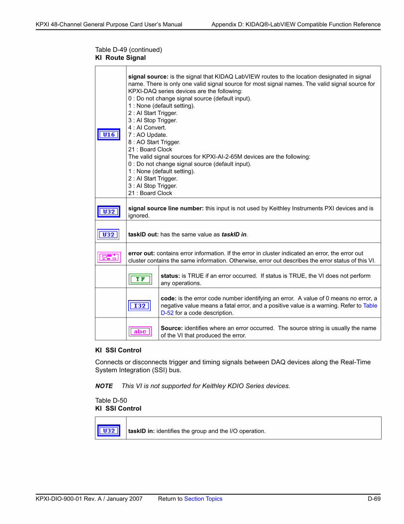
KP
KPXI 48-Channel General Purpose Card User’s Manual Appendix D: KIDAQ®-LabVIEW Compatible Function Reference
KI SSI Control
Connects or disconnects trigger and timing signals between DAQ devices along the Real-Time System Integration (SSI) bus.
NOTE This VI is not supported for Keithley KDIO Series devices.
signal source: is the signal that KIDAQ LabVIEW routes to the location designated in signal name. There is only one valid signal source for most signal names. The valid signal source for KPXI-DAQ series devices are the following:0 : Do not change signal source (default input).1 : None (default setting).2 : AI Start Trigger.3 : AI Stop Trigger.4 : AI Convert.7 : AO Update.8 : AO Start Trigger.21 : Board ClockThe valid signal sources for KPXI-AI-2-65M devices are the following:0 : Do not change signal source (default input).1 : None (default setting).2 : AI Start Trigger.3 : AI Stop Trigger.21 : Board Clock
signal source line number: this input is not used by Keithley Instruments PXI devices and is ignored.
taskID out: has the same value as taskID in.
error out: contains error information. If the error in cluster indicated an error, the error out cluster contains the same information. Otherwise, error out describes the error status of this VI.
status: is TRUE if an error occurred. If status is TRUE, the VI does not perform any operations.
code: is the error code number identifying an error. A value of 0 means no error, a negative value means a fatal error, and a positive value is a warning. Refer to Table D-52 for a code description.
Source: identifies where an error occurred. The source string is usually the name of the VI that produced the error.
Table D-50 KI SSI Control
taskID in: identifies the group and the I/O operation.
Table D-49 (continued)KI Route Signal
XI-DIO-900-01 Rev. A / January 2007 Return to Section Topics D-69
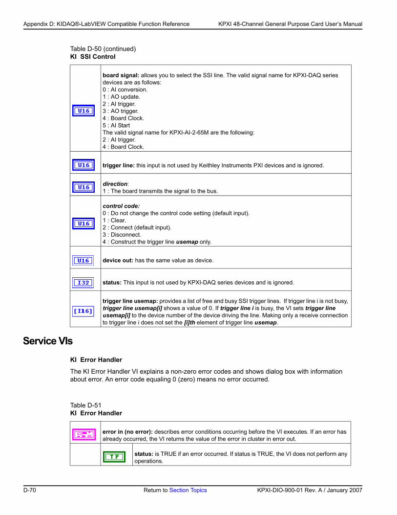
Appendix D: KIDAQ®-LabVIEW Compatible Function Reference KPXI 48-Channel General Purpose Card User’s Manual
Service VIsKI Error Handler
The KI Error Handler VI explains a non-zero error codes and shows dialog box with information about error. An error code equaling 0 (zero) means no error occurred.
board signal: allows you to select the SSI line. The valid signal name for KPXI-DAQ series devices are as follows:0 : AI conversion.1 : AO update.2 : AI trigger.3 : AO trigger.4 : Board Clock.5 : AI StartThe valid signal name for KPXI-AI-2-65M are the following:2 : AI trigger.4 : Board Clock.
trigger line: this input is not used by Keithley Instruments PXI devices and is ignored.
direction: 1 : The board transmits the signal to the bus.
control code:0 : Do not change the control code setting (default input).1 : Clear. 2 : Connect (default input). 3 : Disconnect. 4 : Construct the trigger line usemap only.
device out: has the same value as device.
status: This input is not used by KPXI-DAQ series devices and is ignored.
trigger line usemap: provides a list of free and busy SSI trigger lines. If trigger line i is not busy, trigger line usemap[i] shows a value of 0. If trigger line i is busy, the VI sets trigger line usemap[i] to the device number of the device driving the line. Making only a receive connection to trigger line i does not set the [i]th element of trigger line usemap.
Table D-51 KI Error Handler
error in (no error): describes error conditions occurring before the VI executes. If an error has already occurred, the VI returns the value of the error in cluster in error out.
status: is TRUE if an error occurred. If status is TRUE, the VI does not perform any operations.
Table D-50 (continued)KI SSI Control
D-70 Return to Section Topics KPXI-DIO-900-01 Rev. A / January 2007
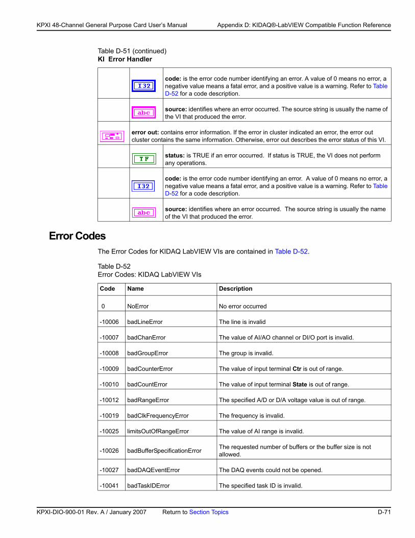
KP
KPXI 48-Channel General Purpose Card User’s Manual Appendix D: KIDAQ®-LabVIEW Compatible Function Reference
Error Codes The Error Codes for KIDAQ LabVIEW VIs are contained in Table D-52.
code: is the error code number identifying an error. A value of 0 means no error, a negative value means a fatal error, and a positive value is a warning. Refer to Table D-52 for a code description.
source: identifies where an error occurred. The source string is usually the name of the VI that produced the error.
error out: contains error information. If the error in cluster indicated an error, the error out cluster contains the same information. Otherwise, error out describes the error status of this VI.
status: is TRUE if an error occurred. If status is TRUE, the VI does not perform any operations.
code: is the error code number identifying an error. A value of 0 means no error, a negative value means a fatal error, and a positive value is a warning. Refer to Table D-52 for a code description.
source: identifies where an error occurred. The source string is usually the name of the VI that produced the error.
Table D-52 Error Codes: KIDAQ LabVIEW VIs
Code Name Description
0 NoError No error occurred
-10006 badLineError The line is invalid
-10007 badChanError The value of AI/AO channel or DI/O port is invalid.
-10008 badGroupError The group is invalid.
-10009 badCounterError The value of input terminal Ctr is out of range.
-10010 badCountError The value of input terminal State is out of range.
-10012 badRangeError The specified A/D or D/A voltage value is out of range.
-10019 badClkFrequencyError The frequency is invalid.
-10025 limitsOutOfRangeError The value of AI range is invalid.
-10026 badBufferSpecificationError The requested number of buffers or the buffer size is not allowed.
-10027 badDAQEventError The DAQ events could not be opened.
-10041 badTaskIDError The specified task ID is invalid.
Table D-51 (continued)KI Error Handler
XI-DIO-900-01 Rev. A / January 2007 Return to Section Topics D-71
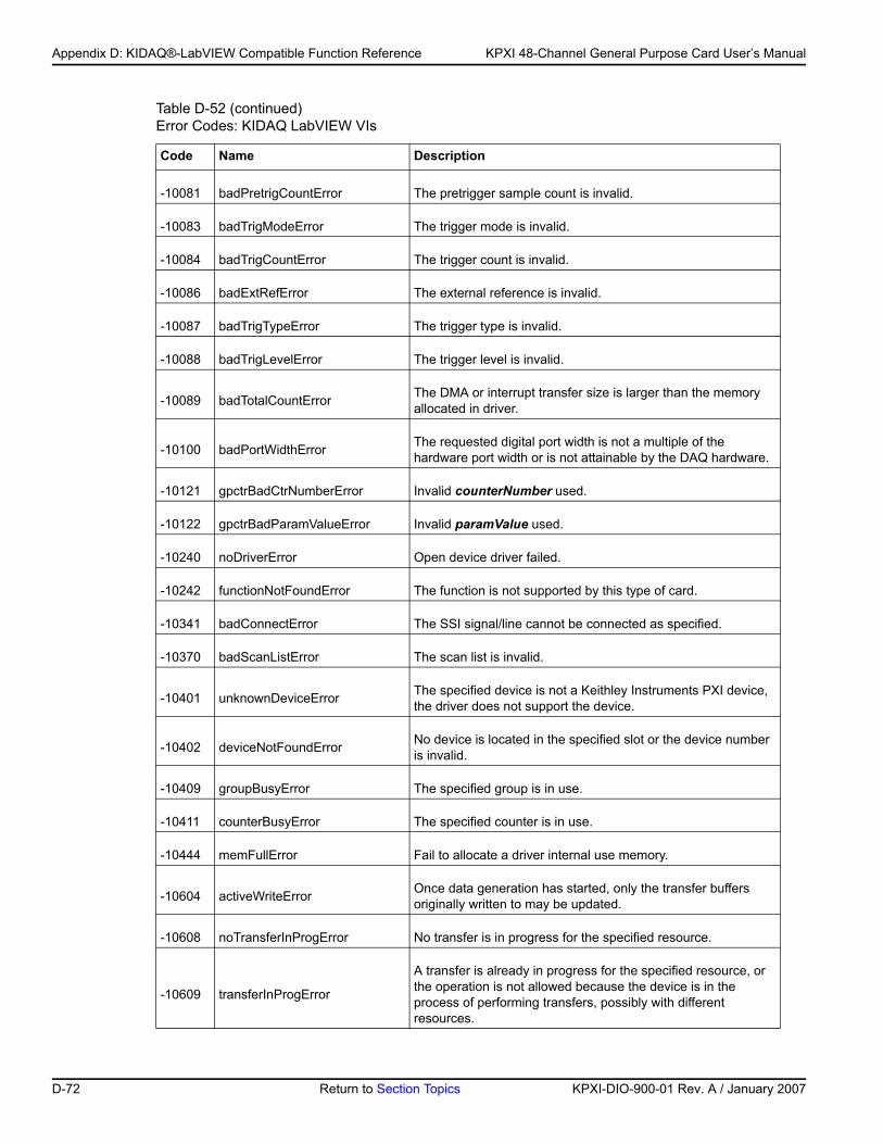
Appendix D: KIDAQ®-LabVIEW Compatible Function Reference KPXI 48-Channel General Purpose Card User’s Manual
-10081 badPretrigCountError The pretrigger sample count is invalid.
-10083 badTrigModeError The trigger mode is invalid.
-10084 badTrigCountError The trigger count is invalid.
-10086 badExtRefError The external reference is invalid.
-10087 badTrigTypeError The trigger type is invalid.
-10088 badTrigLevelError The trigger level is invalid.
-10089 badTotalCountError The DMA or interrupt transfer size is larger than the memory allocated in driver.
-10100 badPortWidthError The requested digital port width is not a multiple of the hardware port width or is not attainable by the DAQ hardware.
-10121 gpctrBadCtrNumberError Invalid counterNumber used.
-10122 gpctrBadParamValueError Invalid paramValue used.
-10240 noDriverError Open device driver failed.
-10242 functionNotFoundError The function is not supported by this type of card.
-10341 badConnectError The SSI signal/line cannot be connected as specified.
-10370 badScanListError The scan list is invalid.
-10401 unknownDeviceError The specified device is not a Keithley Instruments PXI device, the driver does not support the device.
-10402 deviceNotFoundError No device is located in the specified slot or the device number is invalid.
-10409 groupBusyError The specified group is in use.
-10411 counterBusyError The specified counter is in use.
-10444 memFullError Fail to allocate a driver internal use memory.
-10604 activeWriteError Once data generation has started, only the transfer buffers originally written to may be updated.
-10608 noTransferInProgError No transfer is in progress for the specified resource.
-10609 transferInProgError
A transfer is already in progress for the specified resource, or the operation is not allowed because the device is in the process of performing transfers, possibly with different resources.
Table D-52 (continued)Error Codes: KIDAQ LabVIEW VIs
Code Name Description
D-72 Return to Section Topics KPXI-DIO-900-01 Rev. A / January 2007
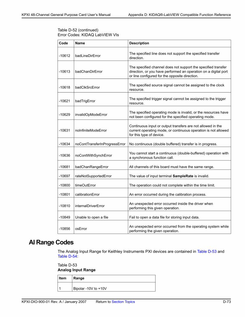
KP
KPXI 48-Channel General Purpose Card User’s Manual Appendix D: KIDAQ®-LabVIEW Compatible Function Reference
AI Range Codes The Analog Input Range for Keithley Instruments PXI devices are contained in Table D-53 and Table D-54:
-10612 badLineDirError The specified line does not support the specified transfer direction.
-10613 badChanDirErrorThe specified channel does not support the specified transfer direction, or you have performed an operation on a digital port or line configured for the opposite direction.
-10618 badClkSrcError The specified source signal cannot be assigned to the clock resource.
-10621 badTrigError The specified trigger signal cannot be assigned to the trigger resource.
-10629 invalidOpModeError The specified operating mode is invalid, or the resources have not been configured for the specified operating mode.
-10631 noInfiniteModeErrorContinuous input or output transfers are not allowed in the current operating mode, or continuous operation is not allowed for this type of device.
-10634 noContTransferInProgressError No continuous (double buffered) transfer is in progress.
-10636 noContWithSynchError You cannot start a continuous (double-buffered) operation with a synchronous function call.
-10681 badChanRangeError All channels of this board must have the same range.
-10697 rateNotSupportedError The value of input terminal SampleRate is invalid.
-10800 timeOutError The operation could not complete within the time limit.
-10801 calibrationError An error occurred during the calibration process.
-10810 internalDriverError An unexpected error occurred inside the driver when performing this given operation.
-10849 Unable to open a file Fail to open a data file for storing input data.
-10856 osError An unexpected error occurred from the operating system while performing the given operation.
Table D-53 Analog Input Range
Item Range
1 Bipolar -10V to +10V
Table D-52 (continued)Error Codes: KIDAQ LabVIEW VIs
Code Name Description
XI-DIO-900-01 Rev. A / January 2007 Return to Section Topics D-73
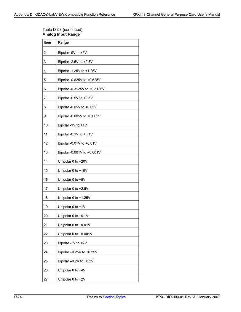
Appendix D: KIDAQ®-LabVIEW Compatible Function Reference KPXI 48-Channel General Purpose Card User’s Manual
2 Bipolar -5V to +5V
3 Bipolar -2.5V to +2.5V
4 Bipolar -1.25V to +1.25V
5 Bipolar -0.625V to +0.625V
6 Bipolar -0.3125V to +0.3125V
7 Bipolar -0.5V to +0.5V
8 Bipolar -0.05V to +0.05V
9 Bipolar -0.005V to +0.005V
10 Bipolar -1V to +1V
11 Bipolar -0.1V to +0.1V
12 Bipolar -0.01V to +0.01V
13 Bipolar -0.001V to +0.001V
14 Unipolar 0 to +20V
15 Unipolar 0 to +10V
16 Unipolar 0 to +5V
17 Unipolar 0 to +2.5V
18 Unipolar 0 to +1.25V
19 Unipolar 0 to +1V
20 Unipolar 0 to +0.1V
21 Unipolar 0 to +0.01V
22 Unipolar 0 to +0.001V
23 Bipolar -2V to +2V
24 Bipolar –0.25V to +0.25V
25 Bipolar –0.2V to +0.2V
26 Unipolar 0 to +4V
27 Unipolar 0 to +2V
Table D-53 (continued)Analog Input Range
Item Range
D-74 Return to Section Topics KPXI-DIO-900-01 Rev. A / January 2007
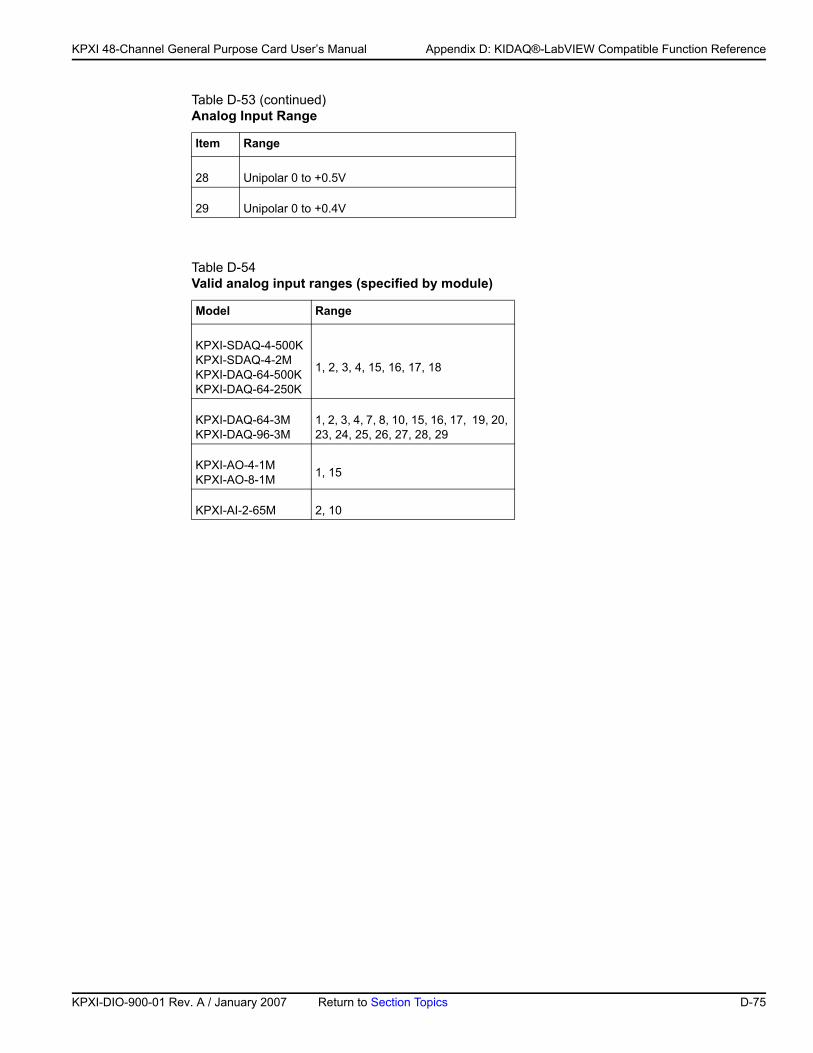
KP
KPXI 48-Channel General Purpose Card User’s Manual Appendix D: KIDAQ®-LabVIEW Compatible Function Reference
28 Unipolar 0 to +0.5V
29 Unipolar 0 to +0.4V
Table D-54 Valid analog input ranges (specified by module)
Model Range
KPXI-SDAQ-4-500KKPXI-SDAQ-4-2MKPXI-DAQ-64-500KKPXI-DAQ-64-250K
1, 2, 3, 4, 15, 16, 17, 18
KPXI-DAQ-64-3MKPXI-DAQ-96-3M
1, 2, 3, 4, 7, 8, 10, 15, 16, 17, 19, 20, 23, 24, 25, 26, 27, 28, 29
KPXI-AO-4-1MKPXI-AO-8-1M 1, 15
KPXI-AI-2-65M 2, 10
Table D-53 (continued)Analog Input Range
Item Range
XI-DIO-900-01 Rev. A / January 2007 Return to Section Topics D-75
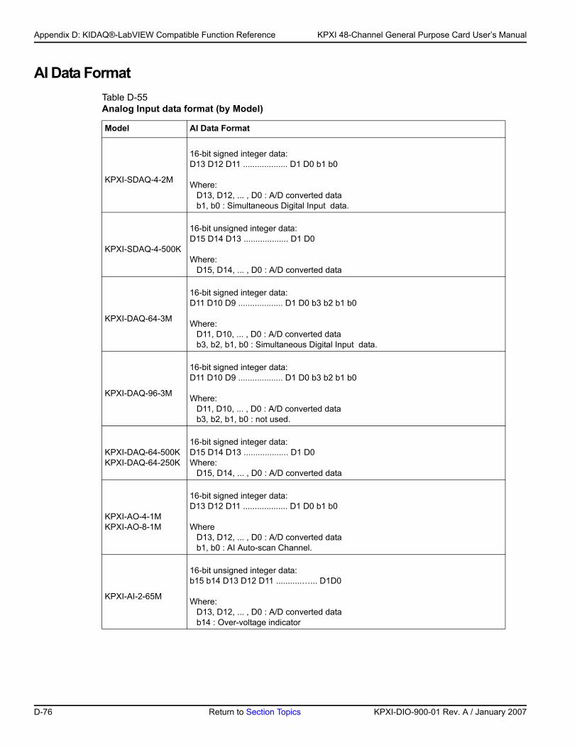
Appendix D: KIDAQ®-LabVIEW Compatible Function Reference KPXI 48-Channel General Purpose Card User’s Manual
AI Data Format Table D-55Analog Input data format (by Model)
Model AI Data Format
KPXI-SDAQ-4-2M
16-bit signed integer data:D13 D12 D11 ................... D1 D0 b1 b0
Where: D13, D12, ... , D0 : A/D converted datab1, b0 : Simultaneous Digital Input data.
KPXI-SDAQ-4-500K
16-bit unsigned integer data:D15 D14 D13 ................... D1 D0
Where:D15, D14, ... , D0 : A/D converted data
KPXI-DAQ-64-3M
16-bit signed integer data:D11 D10 D9 ................... D1 D0 b3 b2 b1 b0
Where:D11, D10, ... , D0 : A/D converted datab3, b2, b1, b0 : Simultaneous Digital Input data.
KPXI-DAQ-96-3M
16-bit signed integer data:D11 D10 D9 ................... D1 D0 b3 b2 b1 b0
Where:D11, D10, ... , D0 : A/D converted datab3, b2, b1, b0 : not used.
KPXI-DAQ-64-500K KPXI-DAQ-64-250K
16-bit signed integer data:D15 D14 D13 ................... D1 D0Where:
D15, D14, ... , D0 : A/D converted data
KPXI-AO-4-1M KPXI-AO-8-1M
16-bit signed integer data:D13 D12 D11 ................... D1 D0 b1 b0
WhereD13, D12, ... , D0 : A/D converted datab1, b0 : AI Auto-scan Channel.
KPXI-AI-2-65M
16-bit unsigned integer data:b15 b14 D13 D12 D11 ...........…... D1D0
Where:D13, D12, ... , D0 : A/D converted datab14 : Over-voltage indicator
D-76 Return to Section Topics KPXI-DIO-900-01 Rev. A / January 2007
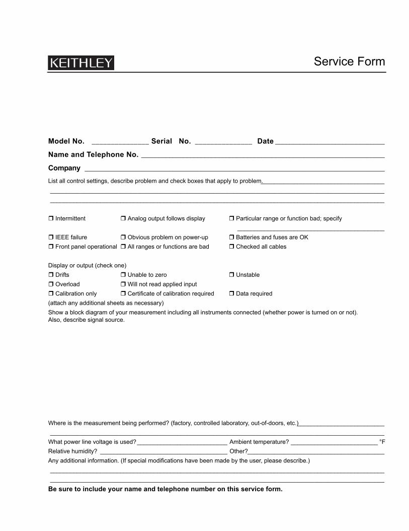
Service Form
Model No. _______________ Serial No. _______________ Date _______________________________
Name and Telephone No. _____________________________________________________________________
Company _____________________________________________________________________________________
List all control settings, describe problem and check boxes that apply to problem._____________________________________________________________________________________________________________________________________________________________________________________________________________________________________________
Intermittent Analog output follows display Particular range or function bad; specify____________________________________________
IEEE failure Obvious problem on power-up Batteries and fuses are OKFront panel operational All ranges or functions are bad Checked all cables
Display or output (check one)Drifts Unable to zero UnstableOverload Will not read applied inputCalibration only Certificate of calibration required Data required
(attach any additional sheets as necessary)Show a block diagram of your measurement including all instruments connected (whether power is turned on or not). Also, describe signal source.
Where is the measurement being performed? (factory, controlled laboratory, out-of-doors, etc.)______________________________________________________________________________________________________________________________
What power line voltage is used?___________________________ Ambient temperature? __________________________ °FRelative humidity? ______________________________________ Other? _________________________________________Any additional information. (If special modifications have been made by the user, please describe.)________________________________________________________________________________________________________________________________________________________________________________________________________
Be sure to include your name and telephone number on this service form.


12/06
Specifications are subject to change without notice.
All Keithley trademarks and trade names are the property of Keithley Instruments, Inc.
All other trademarks and trade names are the property of their respective companies.
A G R E A T E R M E A S U R E O F C O N F I D E N C E
Keithley Instruments, Inc.
Corporate Headquarters • 28775 Aurora Road • Cleveland, Ohio 44139 • 440-248-0400 • Fax: 440-248-6168 • 1-888-KEITHLEY • www.keithley.com