Embed Size (px)
Citation preview

ATTEL PERFORMANCE‐BASED APPROACHES FOR HIGH STRENGTH TUBULAR COLUMNS AND CONNECTIONS UNDER EARTHQUAKE AND FIRE LOADINGS RFSR‐CT‐2008‐00037
Deliverable (D1.1):“State‐of‐the‐art report on nd evaluation of experimental test sign procedures”.
collection adata and de
Laboratory of Mechanics & Strength of Materials Mechanical Engineering
UNIVERSITY OF THESSALY
Work package leader: University of Thessaly Contributing partners: University of Trento
University of Liège Centro Sviluppo Materiali SPA Stahlbau Pichler SRL
March 2010
ATTEL – Deliverable D1 – Work Package1 – March 2010
Lab. Mechanics & Strength of Materials, University of Thessaly 2
PERFORMANCE‐BASED APPROACHES FOR HIGH STRENGTH TUBULAR COLUMNS AND CONNECTIONS UNDER EARTHQUAKE AND FIRE LOADINGS (ATTEL)
RFSR‐CT‐2008‐00037 Work Package 1‐ Deliverable1 State‐of‐the‐art report on collection and evaluation of experimental test data and design procedures Prepared by:
Aglaia Pournara & George E. Varelis Approved by:
Spyros A. Karamanos
Laboratory of Mechanics & Strength of Materials Department of Mechanical Engineering UNIVERSITY OF THESSALY Contributing partners: University of Trento (UNITN)
University of Liège (UNILG) Centro Sviluppo Materiali (CSM)
Stahlbau Pichler (STBPI)
March 2010
ATTEL – Deliverable D1 – Work Package1 – March 2010
Table of contents 1. Static loading .................................................................................................. 5
1.1 High Strength Steel ........................................................................................... 5
1.1.1 Material characteristics of High Strength Steel ............................................ 5
1.1.2 Local and global buckling of high strength steel ........................................... 6
1.1.3 Ductility of HSS elements and sections ......................................................... 7
1.1.4 Classification of cross section for CHS made of HSS ..................................... 7
References .............................................................................................................. 8
1.2 Buckling tests ................................................................................................... 9
1.2.1 ECCS experimental research on column strength of regular steel (experimental basis of European Column Buckling Curves reported in EN1993‐1‐1) ........................................................................................................................... 10
1.2.2Experimental research vs. theoretical analysis of regular steel................... 10
1.2.3 Compression members of high strength steel ............................................ 11
References ............................................................................................................ 13
2 Earthquake loading ........................................................................................... 14
2.1 Tubular CHS and CFT structural members under cyclic bending loading ...... 14
References ............................................................................................................ 15
2.2 Tubular CHS and CFT beam‐columns under monotonic and cyclic loads ...... 16
References ............................................................................................................ 17
3. Structural joints between tubular columns and I‐beams ............................... 18
3.1 Tests on Structural joints between tubular columns and I‐beams ................ 18
References ............................................................................................................ 20
3.2 CIDECT provisions on Structural joints between tubular columns and beams.21
3.2.1 Rigid (full strength) connections to CHS columns ................................. 21
3.2.2 Connections to circular concrete filled columns (CFT) .......................... 23
3.2.2.1 Simple shear connections ......................................................................... 24
3.2.2.2 Semi‐rigid connections........................................................................... 24
3.2.2.3 Rigid (full strength) connections .............................................................. 25
References ............................................................................................................ 28
Lab. Mechanics & Strength of Materials, University of Thessaly 3

ATTEL – Deliverable D1 – Work Package1 – March 2010
4 Fire loading ................................................................................................... 30
4.1 Material properties for concrete and steel at elevated temperature ........... 30
References ............................................................................................................ 32
4.2 Concrete filled hollow section columns [Chu Thi Binh (2009)] ...................... 34
References ............................................................................................................ 35
Lab. Mechanics & Strength of Materials, University of Thessaly 4

ATTEL – Deliverable D1 – Work Package1 – March 2010
1. Static loading 1.1 High Strength Steel
The use of Circular Hollow Section (CHS) and steel‐concrete Composite Filled Tube (CFT) section has recently had a significant development both for their excellent structural and architectural properties. Conversely, the use of high strength steel (HSS)circular hollow sections (CHS) is still very limited in the construction industry. In the construction sector, steel with yield strength from 460 up to 690 MPa is considered HSS. The high‐strength steels have specific chemical compositions which depend primarily on rolling and tempering techniques, element thickness and producers.
High strength steels have become commercial about 3 decades ago. They were, like today, essentially produced by water Quenching and Tempering (QT). In the last years Thermo‐Mechanical Rolling (TM) followed by accelerated cooling has become an alternative production route as reported by Richter et al (2002)[1.1.1] and Varga (1996)[1.1.2].
1.1.1 Material characteristics of High Strength Steel
The stress‐strain behavior of HSS (σ −ε) is considerably different from that of
mild steel, exhibiting considerably lower material ductility. Strain at rupture εrp of HSS ranges from 10% to 15%, strain at ultimate load level εu is about 10% as proved by Sivakumaran & Bing (1998)[1.1.3] and Rasmussen & Hancock (1995) [1.1.4]. It was recently developed the EN 1993‐1‐12 [1.1.5] in order to give rules (additions and changes) to make EN 1993‐1‐1[ 1.1.6] applicable to high strength steel. EN 1993‐1‐12 covers steels according to EN 10025‐6 [1.1.7] and EN 10149‐2[1.1.8]. The former deals with quenched and tempered steels delivered as flat plates and those included in EC3‐1‐12 range from S500 to S690, whereas EN 10149‐2 deals with TM‐ steels for cold forming and the grades included in EN 1993‐1‐12 range from S500 to S700 as reported by Johansson & Collin (2008)[1.1.9]. In EN 1993‐1‐12 three requirements on material behavior and ductility are stated. They are a little different than that stated in EN 1993‐1‐1, i.e.
• u
y
f 1.05f≥
• Elongation at failure not less than 10%
• 15ε ≥ yu
f
E
The restrictions on structures made of steels fulfilling those relaxed requirements are mainly that plastic analysis and semi rigid joints should not be used. The structural analysis should either be elastic or by non‐linear FEM. It should
Lab. Mechanics & Strength of Materials, University of Thessaly 5

ATTEL – Deliverable D1 – Work Package1 – March 2010
Lab. Mechanics & Strength of Materials, University of Thessaly 6
be noted that the plastic resistance may still be used for cross sections in Class 1 and 2 [1.1.9]. Concerning the weldability, it is more difficult to weld quenched and tempered HSS and thermo‐mechanically rolled HSS than mild steel. The more difficult weldability results from the increasing of Carbon Equivalent parameter (CE). However these difficulties must be overcome by precautions in welding. This means higher preheat, and interpass temperature, the application of low hydrogen consumables and possibly soaking after welding for a removal of residual hydrogen [1.1.1], [1.1.3]. Moreover it is known that nickel improves consistently the low temperature toughness in parent material and heat affected zone for QT and normalized steels. If Nickel is added, it can replace carbon, manganese and other alloying elements that are less favourable for the Heat Affected Zone (HAZ) [1.1.1] [1.1.3]. One way of simplifying the welding of HSS is to use undermatched electrodes, which makes the welds more ductile and less prone to crack. Undermatched electrodes are not allowed in EN 1993‐1‐8 [1.1.10] but they are allowed in EN 1993‐1‐12. The design of such undermatched welds should be based on the electrode strength rather than the base material strength [1.1.9]. The results come out from some test to be a modification of the design formula (4.1) of EN 1993‐1‐8 which reads:
2 2 2//2 3
2u eu
M2
f + fσ τ τγ⊥ ⊥+ + ≤
The notations are the same as in EN 1993‐1‐8 with the additional symbol feu meaning the characteristic ultimate strength of the electrodes [1.1.9].
1.1.2 Local and global buckling of high strength steel
There are numerous studies on the effect of buckling on structures of HSS
[1.1.9]. In general those studies show that HSS performs better than ordinary steel or at least not worse [1.1.3], [1.1.4], [1.1.11]. This means that the normal design rules can be used as a conservative approach. The reason for the better behaviour of HSS is a smaller influence of imperfections and lower influence of residual stresses because the value of the ratio between residual stresses and yield strength is small [1.1.3], [1.1.4], [1.1.12].
Studies and tests on long box and I‐section columns fabricated from HSS have shown that the buckling behaviour of these sections is better than that described in Eurocode [1.1.4]. In fact the Eurocode 3 design curves are conservative compared with the tests and with Australian, American and British specifications. This is because the slenderness reduction factor due to flexural buckling ( χ ) in the Eurocode is more penalised than the Australian [1.1.13] and American AISC [1.1.14] specifications. Moreover this factor in Eurocode is not function of the yield stress as in the British Standard BS5950 [1.1.15]. The difference between Eurocode and British Standard is inside the imperfection parameter:

ATTEL – Deliverable D1 – Work Package1 – March 2010
Lab. Mechanics & Strength of Materials, University of Thessaly 7
( 0,2η α λ= − ) (EN1993‐1‐1)
( )2
0,001 0,2yf
πη α λΕ= − (BS5950)
( )2 2
2
1
0,5 1
χϕ φ λ
ϕ η λ
=+ +
= + +
Therefore a more rational way to account for the increased relative resistance would be to give a gradual increase of the buckling curves by modifying the imperfection parameter as reported by Bernt Johansson & Collin [1.1.9].
A direct use of these results is not suggested for other kind of section such as CHS because it is necessary to carry out analytic, numerical and experimental tests on these sections.
1.1.3 Ductility of HSS elements and sections
Several studies have verified the difficulty of using plastic analysis for high strength steel elements due to the reduced ductility parameters of the material [1.1.3]. The ratio between the tensile strength (fu) and the yield strength (fy) is considerably lower than that of mild steel; the ratio between the strain at hardening (εst), and the strain at yielding (εy) is about 1, so that there isn’t a horizontal plateau after the yield strength; the ratio between the strain at ultimate load level (εu), and the strain at yielding (εy ) is considerably lower than that of mild steel [1.1.3]. However these studies were carried out on H section and are not directly extensible to circular sections. In conclusion, we can say that the ductility of material and section for HSS elements can be considered lower than that of ordinary steel and hence need to pay particular attention to use plastic analysis, particularly in seismic conditions.
1.1.4 Classification of cross section for CHS made of HSS
The classification of cross sections is closely related to the ductility of the material, the ductility of the element section and the local buckling phenomena. An important problem of HSS section, owing to the high yield strength, consists of respecting the classification limits imposed by Eurocode 3‐1‐1. The classification of cross sections is function of the factor
235
yfε =
so that HSS is penalized. In addition the classification is function of D/t that is often high with use of HSS sections. Beg & Hladnik [1.1.11] and Elchalakani et al [1.1.16] have shown that the slenderness limits in EC3‐1‐1 are probably too conservative both for mild steel up to grade S460 and for HSS, in particular for circular hollow

ATTEL – Deliverable D1 – Work Package1 – March 2010
Lab. Mechanics & Strength of Materials, University of Thessaly 8
section. There are significant differences in slenderness limits recommended in various codes for circular hollow sections (CHS) under bending as shown by Elchalakani et al [1.1.16].
Cross section classification AS 4100
(1) AISC‐LRFD
(2) Eurocode 3 & CIDECT (3)
NZS 3404 (4)
λs ≤ 50 Compact
λs ≤ 50 Compact
λs ≤ 47 Class 1
λs ≤ 50 Class 1
50 < λs ≤120 Non‐compact
50 < λs ≤250 Non‐compact
47< λs ≤66 Class 2
50 < λs ≤65 Class 2
66< λs ≤84
Class 3
65 < λs ≤170 Class 3
λs >120 Slender
λs >250 Slender
λs >84 Class 4
λs >170 Class 4
Table 1 Cross section classification for different standards
2
2 250
s
y
D/t=
f
λε
ε =
Other research by Al‐Shawi [1.1.17] aimed at studying the behaviour and the
rotational capacity of CHS in the plastic range in order to investigate the behaviour of circular hollow sections beyond the stage of development of the plastic moment of resistance. In the standards, the possibility to develop plastic moment Mp is fitted in the classification of cross sections. But in this way it does not take into account the secondary P–Δ effect which takes place in the plane of the cross section of the tube. This effect will reduce the plastic section (ovalization) modulus due to the deformation in the form of flattening of the cross section [1.1.17]. It is therefore necessary to perform experiments and tests with regard to these issues, mainly investigating the behaviour of circular sections in HSS.
References
1.1.1 Richter, Hanus, Wolf “Structural Steels of 690 MPa Yield Strength – a
State of Art”, 2nd International Symposium on High Strength Steel, Stiklestad, Verdal 23‐24 April, 2002.
1.1.2 T. Varga “Safety of welded modern high strength steel constructions, in particular bridges”, Welding in the world, vol. 38 pp. 1‐22, 1996.

ATTEL – Deliverable D1 – Work Package1 – March 2010
1.1.3 Sivakumaran K.S.; Bing Y. “Slenderness limit and ductility of high strength steel sections”, Journal of Constructional Steel Research, Volume 46, Number 1, April 1998 , pp. 149‐151
1.1.4 Rasmussen, Hancock “Test of High Strength Steel Columns” J. Construct Steel Research 34 (1995), 27‐52.
1.1.5 CEN EN 1993‐1‐12. “Eurocode 3: Design of steel structures. Part 1.12: Additional rules for the extension of EN 1993 up to steel grades S 700.” European Committee for Standardization, Feb 1, 2007
1.1.6 CEN EN 1993‐1‐1. “Eurocode 3: Design of steel structures. Part 1‐1: General rules and rules for buildings.” European Committee for Standardization. May 1, 2005.
1.1.7 CEN EN 10025‐6. “Hot rolled products of structural steels. Part 6: Technical delivery conditions for flat products of high yield strength structural steels in the quenched and tempered condition”,European Committee for Standardization, Apr 1, 2005.
1.1.8 CEN EN 10149‐2, “Hot‐Rolled Flat Products Made of High Yield Strength Steels for Cold Forming ‐ Part 2: Delivery Conditions for Thermomechanically Rolled Steels” European Committee for Standardization. Sep 1, 1995
1.1.9 Bernt Johansson, Peter Collin, “Eurocode for high strength steel and applications in construction,” Lulea University of Technology, Sweden.
1.1.10 CEN EN 1993‐1‐8. “Eurocode 3: Design of steel structures. Part 1‐8: Design of joints.” European Committee for Standardization. May 1, 2005
1.1.11 Beg, Hladnik “Slenderness limit of Class 3 I cross‐sections made of high strength steel”, Journal of Constructional Steel Research, Volume 38, Number 3, July 1996 , pp. 201‐217
1.1.12 H. Jiao, X.‐L. Zhao “Imperfection, residual stress and yield slenderness limit of very high strength (VHS) circular steel tubes”, Journal of Constructional Steel Research, Volume 59, Number 2, February 2003 , pp. 233‐249
1.1.13 Standards Association of Australia, 1990, ‘AS 4100‐1990 Steel Structures’, Standards Australia
1.1.14 American Institute of Steel Construction, 2005, « Steel Construction Manual ‐ Thirteenth Edition, AISC 325‐05
1.1.15 British Standard, 2000, “Structural use of steelwork in building. Code of practice for design. Rolled and welded sections" BS 5950‐1:2000
1.1.16 Elchalakani, Zhao, Grzebieta “Bending tests to determine slenderness limits for cold‐formed circular hollow sections”, Journal of Constructional Steel Research, Volume 58, Number 11, November 2002, pp. 1407‐1430
1.1.17 F.A.N. Al‐Shawi “On the rotation capacity of structural steel circular hollow sections in plastic analysis”, Journal of Constructional Steel Research, Volume 57, Number 1, January 2001,pp. 29‐43.
1.2 Buckling tests
Lab. Mechanics & Strength of Materials, University of Thessaly 9

ATTEL – Deliverable D1 – Work Package1 – March 2010
1.2.1 ECCS experimental research on column strength of regular steel (experimental basis of European Column Buckling Curves reported in EN1993‐1‐1)
The ECCS (European Convention for Constructional Steelwork) testing
programme on column strength has included 1067 main buckling tests on various types of members (I, H, T, round and square hollow sections) and the corresponding stub and tension tests. It covered the range of slenderness ratios most frequently used in European constructional practice (in fact 55 – 75 – 95 – 130 – 160). Stub tests were made with l/r = 20 and fixed ends. This research has been described by D. Sfintesco [1.2.1] and Jacquet [1.2.3]. The cross‐sectional dimensions of the test pieces were limited in this programme by the force and height of the testing machines. Therefore the range of heavier sections with greater thicknesses had not been covered.
Thanks to the interest shown by CRC for this research, a complementary programme jointly sponsored by WRC, NSF, and ECCS has been carried out at Lehigh University (Fritz Lab) on columns of a relatively (i.e. accordingly to European standards) heavier section. The test pieces were collected in various European countries along the same rules as for the main programme.
These additional tests have been completed the information needed for establishing the ECCS column curves. They also gave the opportunity of a comparison between the ECCS and the Lehigh testing procedures. It has been reported on this research in papers by N. Tebedge et al [1.2.4].
1.2.2 Experimental research vs. theoretical analysis of regular steel
The following figures compare the statistically evaluated column tests with theoretical column curves. Figure 1 shows the test results for rolled tubes, Figure 2 for welded tubes, hot‐finished. For the comparison curve “a”, the design curve for tubes, is evaluated with the statistically determined yield point of the tubes tested, and is in good agreement with the test results. Also, the comparison shows clearly the lower load carrying capacity of welded tubes in the range of small slenderness ratios l.
Lab. Mechanics & Strength of Materials, University of Thessaly 10

ATTEL – Deliverable D1 – Work Package1 – March 2010
Figure 1 ECCS test results for rolled tubes.
Figure 2 ECCS test for welded tubes, hot‐finished.
1.2.3 Compression members of high strength steel
Design rules for columns of high yield strength steel (S460 at that time) have been included in the Eurocode to allow designers to take advantage, not only of their obvious enhanced load‐bearing capacity due to increased material strength, but of
Lab. Mechanics & Strength of Materials, University of Thessaly 11

ATTEL – Deliverable D1 – Work Package1 – March 2010
additional strength conferred on columns due to lessening of detrimental effect of residual stresses. One of the more favourable cross‐sectional shapes for a column is of a circular tube. Beer and Schulz [1.2.6] have computed the column curve for such cross‐section assuming no residual stresses and a diameter to wall thickness ratio of 40. This column curve has been given the designation “a0” and represents an approximate upper bound to the strength of tubular columns having an initial bow of 1/1000 of the column length. Experimental results for the buckling of hot‐finished welded, round and square tubes have been obtained at the University of Liège [1.2.7]. The steel had a yield stress in excess of 700 MPa. The tubular columns were tested at six values of non dimensional slenderness and the results are shown plotted in Figure 3. Each point represents the mean strength from eight tests less twice the standard deviation except at non dimensional slenderness equal to 1.7 where only three tests were performed. Experimental failure stresses in Figure 3 are non‐dimensionalised with respect of guaranteed minimum yield stress (mean yield stress less twice the standard deviation) to conform with the Eurocode column curve for hot‐finished welded tubes.
Figure 3 ‐ Experimental results for the buckling of hot‐finished welded, round and square tubes made of high strength steel.
A series of tests on rolled, heat‐treated circular tubes of steel having a mean yield stress of 654 MPa has been carried out by Milan Polytechnic [1.2.8]. Twelve tests have been performed at a non‐dimensional slenderness ratio of 1.1. The single point shown on Figure 3 represents the mean of the twelve results less twice the standard deviation divided by the mean yield stress less twice the standard deviation. Figure 3 shows that most of the experimental results are between curves “a” and “a0”. It is possible in the future that manufacturing processes of high yield strength tubes will be improved to allow such section to be designed according to curve “a0”.
Lab. Mechanics & Strength of Materials, University of Thessaly 12

ATTEL – Deliverable D1 – Work Package1 – March 2010
References
1.2.1 Sfintesco, D. European Steel Column Research, ASCE Struct. Engg. Conf.
(Preprints 502), Seattle Washington, May 1967. 1.2.2 Sfintesco, D. Fondement expérimental des courbes européennes de
flambement (Experimental basis of the European column curves), Construction Métallique No 3, Sept. 1970.
1.2.3 Jacquet, J. Essais de flambement et exploitation statistique (Buckling tests and their statistical analysis), Construction Métallique No 3, Sept. 1970.
1.2.4 Tebedge, N. et al. Experimental studies on column strength of European heavy shapes, Proc. Internat. Colloquium on Column Strength, Paris 1972 (Published by IABSE).
1.2.5 Tebedge, N. et al. Méthod d’essai de flambement des barres à forte section (Testing methods for heavy columns), Construction Métallique No 4, Dec. 1971.
1.2.6 Beer, H. and Schulz, G., he European column curves, IABSE Int. Coll. On Column Strength, Paris Nov. 1972.
1.2.7 Massonnet, Ch. And Janss, J., Buckling tests on round and square tubes in high yield strength steel carried out for C.R.I.F. in the laboratories of the University of Liège, C.R.I.F. – Internal report (undated, Liège).
1.2.8 Ballio, G., Finzi, L. , Urbano, C. and Zandonini, P., Buckling of tubes in Niguage steel – experimental study and theoretical considerations, Construction Métallique, 1975.
Lab. Mechanics & Strength of Materials, University of Thessaly 13
ATTEL – Deliverable D1 – Work Package1 – March 2010
2 Earthquake loading
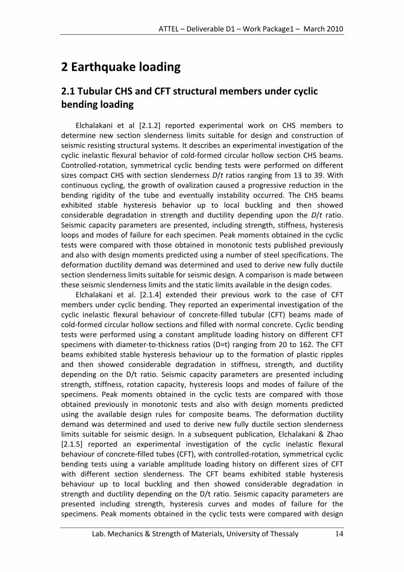
2.1 Tubular CHS and CFT structural members under cyclic bending loading
Elchalakani et al [2.1.2] reported experimental work on CHS members to determine new section slenderness limits suitable for design and construction of seismic resisting structural systems. It describes an experimental investigation of the cyclic inelastic flexural behavior of cold‐formed circular hollow section CHS beams. Controlled‐rotation, symmetrical cyclic bending tests were performed on different sizes compact CHS with section slenderness D/t ratios ranging from 13 to 39. With continuous cycling, the growth of ovalization caused a progressive reduction in the bending rigidity of the tube and eventually instability occurred. The CHS beams exhibited stable hysteresis behavior up to local buckling and then showed considerable degradation in strength and ductility depending upon the D/t ratio. Seismic capacity parameters are presented, including strength, stiffness, hysteresis loops and modes of failure for each specimen. Peak moments obtained in the cyclic tests were compared with those obtained in monotonic tests published previously and also with design moments predicted using a number of steel specifications. The deformation ductility demand was determined and used to derive new fully ductile section slenderness limits suitable for seismic design. A comparison is made between these seismic slenderness limits and the static limits available in the design codes.
Elchalakani et al. [2.1.4] extended their previous work to the case of CFT members under cyclic bending. They reported an experimental investigation of the cyclic inelastic flexural behaviour of concrete‐filled tubular (CFT) beams made of cold‐formed circular hollow sections and filled with normal concrete. Cyclic bending tests were performed using a constant amplitude loading history on different CFT specimens with diameter‐to‐thickness ratios (D=t) ranging from 20 to 162. The CFT beams exhibited stable hysteresis behaviour up to the formation of plastic ripples and then showed considerable degradation in stiffness, strength, and ductility depending on the D/t ratio. Seismic capacity parameters are presented including strength, stiffness, rotation capacity, hysteresis loops and modes of failure of the specimens. Peak moments obtained in the cyclic tests are compared with those obtained previously in monotonic tests and also with design moments predicted using the available design rules for composite beams. The deformation ductility demand was determined and used to derive new fully ductile section slenderness limits suitable for seismic design. In a subsequent publication, Elchalakani & Zhao [2.1.5] reported an experimental investigation of the cyclic inelastic flexural behaviour of concrete‐filled tubes (CFT), with controlled‐rotation, symmetrical cyclic bending tests using a variable amplitude loading history on different sizes of CFT with different section slenderness. The CFT beams exhibited stable hysteresis behaviour up to local buckling and then showed considerable degradation in strength and ductility depending on the D/t ratio. Seismic capacity parameters are presented including strength, hysteresis curves and modes of failure for the specimens. Peak moments obtained in the cyclic tests were compared with design
Lab. Mechanics & Strength of Materials, University of Thessaly 14

ATTEL – Deliverable D1 – Work Package1 – March 2010
moments predicted using a number of steel and concrete specifications. New section slenderness limits suitable for design and construction of seismic resisting structural systems were determined. A comparison is made between these seismic slenderness limits and the limits available in the design codes.
Lee et al. (2001) [2.1.1] presented the experimental results on the influence of the diameter‐to‐thickness ratio (D/t ratio) to the response and stability of circular tubes subjected to symmetrical cyclic bending. To highlight the influence of the D/t ratio to the response and stability of circular tubes under symmetrical cyclic bending, the raw tubes were slightly machined on the outside surface to obtain the desired D/t ratio. However, the magnitudes of the inside diameter were intact and the same for all tested specimens. It was observed that if a certain amount of controlled curvature is considered, specimens with smaller outside diameters have a few number of cycles to produce buckling than these with larger outside diameters. In addition, although four groups of tested specimens had four different D/t ratios, four parallel straight lines can be seen from the relationship between the controlled curvature and the number of cycles to produce buckling in log–log scale. Finally, the empirical relationship, proposed by Kyriakides and Shaw (1987), was modified so that it can be used for simulating the relationship between the controlled curvature and the number of cycles to produce buckling for circular tubes with different D/t ratios. The simulation was compared with the experimental test data. Good agreement between the experimental result and modified empirical relationship has been achieved. In a more recent paper, Chang & Pan [2.1.3] reported an experimental investigation of the degradation and buckling of circular tubes subjected to cyclic bending is discussed. The machinery specimens (with different diameter‐to‐thickness ratios but the same inside diameter) and method of testing (cyclic bending) in this study were the same as the ones used by Lee et al. (2001) [2.1.1] 316L stainless steel circular tubes. The experimental investigation was extended to different outside and inside diameters of the same circular tubes subjected to cyclic bending. Based on the experiments, the empirical formulation proposed by Lee et al. (2001) was modified so that it can now be used to simulate the relationship between the prescribed curvature and the number of cycles necessary to produce buckling. In addition, it was found that the experimental curve of the ovalization and the number of cycles necessary to produce buckling could be divided into three stages – an initial, secondary and final stage. An empirical relationship, similar to the Bailey–Norton creep formulation, was proposed for simulating the aforementioned curve for the initial and secondary stages in this study. The derived empirical relationship was in good agreement with the experimental data.
References
2.1.1 Lee et al. (2001). The influence of the diameter‐to‐thickness ratio on the
stability of circular tubes under cyclic bending. International Journal of Solids and Structures 38, 2401–2413.
Lab. Mechanics & Strength of Materials, University of Thessaly 15

ATTEL – Deliverable D1 – Work Package1 – March 2010
2.1.2 Elchalakani M, Zhao XL, Grzebieta RH. Cyclic bending tests to determine fully ductile slenderness limits for cold‐formed circular hollow sections. J Struct Engrg ASCE 2004;130(7):1001–10.
2.1.3 Kao‐Hua Chang and Wen‐Fung Pan. “Buckling life estimation of circular
tubes under cyclic bending”. International Journal of Solids and Structures 46 (2009) 254–270
2.1.4 Mohamed Elchalakani, Xiao‐Ling Zhao and Raphael Grzebieta (2004),
“Concrete‐filled steel circular tubes subjected to constant amplitude cyclic pure bending”, Engineering Structures 26, 2125–2135
2.1.5 Mohamed Elchalakani and Xiao‐Ling Zhao (2008), “Concrete‐filled cold‐
formed circular steel tubes subjected to variable amplitude cyclic pure bending”, Engineering Structures 30, 287–299.
2.2 Tubular CHS and CFT beam‐columns under monotonic and cyclic loads
The pioneering works of Furlong (1967, 1968) [2.2.1], [2.2.2], Gardner & Jacobson (1967) [2.2.3] and those by Knowles & Park (1969, 1970) [2.2.4], [2.2.5], constitute an extensive experimental data base, which is still useful in investigating the structural behavior of CFT columns and beam‐columns. More recently, the paper by Schneider (1998) [2.2.6], reported experimental and analytical results on short, concrete‐filled steel tubes loaded concentrically in compression. Fourteen specimens were tested to investigate the effect of the steel shape and wall thickness on the ultimate strength of the composite column. The results were compared with existing design specifications for CFT column design. The experimental results indicated that circular tubes offer substatinal post‐yield strength and stiffness.
The behavior of concrete‐filled circular and square steel tubular CFT beam‐columns with a variety of material strengths was investigated experimentally by Inai et al. (2004) [2.2.7]. The main test parameters are steel strength 400, 590, and 780 MPa, diameter‐ width‐to‐thickness ratio of steel tube, and concrete strength between 40 and 90 MPa. The interior beam‐column models were tested under constant axial compression and cyclic horizontal load with incrementally increasing lateral deformation to clarify the effects of the test parameters on the behavior. The exterior beam‐column models were laterally loaded under variable axial load, including axial tension. The behavior of square beam columns subjected to biaxial bending was also investigated. The test results show that higher strength and thicker steel tubes give better overall behavior of the beam column, while higher strength concrete has an adverse effect on the behavior. Furthermore, computer simulations for the hysteretic behavior of CFT beam‐column specimens are presented here. The analytical results show excellent agreement with the test results except for a few cases.
Lab. Mechanics & Strength of Materials, University of Thessaly 16

ATTEL – Deliverable D1 – Work Package1 – March 2010
The behavior of concrete‐filled tube columns under seismic loads was studied by Elremaily et al. (2002) [2.2.8]. Six columns were tested, subjected to a constant axial load in addition to a cyclic lateral load. The test parameters included the level of axial load, the diameter‐to‐thickness ratio of the steel tube, and the concrete compressive strength. The test columns showed high ductility and maintained their strength up to the end of the test. The test results also indicate that the column capacity was significantly improved due to the concrete strength gained from the confinement provided by the steel tube. An analytical model was developed to predict the capacity of circular CFT beam–columns accounting for the interaction between the steel and concrete. The analytical model is compared with the experimental data reported in this paper and those reported by other researchers. Good agreement was observed between the predicted values using the proposed model and the experimental results.
References
2.2.1 Furlong, R. W. (1967), ‘‘Strength of steel‐encased concrete beam‐
columns.’’ J. Struct. Div. ASCE, 93 (5), 113–124.
2.2.2 Furlong, R. W. (1968), ‘‘Design of steel‐encased concrete beam‐columns.’’ J. Struct. Div. ASCE, 94 (1), 267–281.
2.2.3 Gardner, N. J. and Jacobson, E. R. (1967), Structural behavior of concrete
filled steel tubes”, ACI Journal, 64 (7), 404‐412.
2.2.4 Knowles, R. B. and Park, R., “Strength of concrete‐filled steel tubular columns”, J. Struct. Div. ASCE, 95 (12), 2565–2587.
2.2.5 Knowles, R. B. and Park, R., “Axial load design of concrete‐filled steel
tubes”, J. Struct. Div. ASCE, 96 (10), 2125–2153.
2.2.6 Schneider. S. P. (1998), Axially‐loaded concrete‐filled steel tubes”, J. Struct. Eng. ASCE, 124 (10).
2.2.7 Eiichi Inai; Akiyoshi Mukai; Makoto Kai; Hiroyoshi Tokinoya; Toshiyuki
Fukumoto; and Koji Mori, (2004) Behavior of Concrete‐Filled Steel Tube Beam Columns, Journal of Structural Engineering, Vol. 130, No. 2.
2.2.8 Ahmed Elremaily, Atorod Azizinamini, “Behavior and strength of circular
concrete‐filled tube columns”, Journal of Constructional Steel Research 58 (2002) 1567–1591
Lab. Mechanics & Strength of Materials, University of Thessaly 17

ATTEL – Deliverable D1 – Work Package1 – March 2010
3. Structural joints between tubular columns and I‐beams
3.1 Tests on Structural joints between tubular columns and I‐beams
An interesting paper was reported by Schneider and Alostaz (1998) [3.1.1]. Six large‐scale connections were tested to failure using the quasi‐static test method. All details consisted of a connection‐stub which was shop fabricated and field bolted for construction. Experimental results indicated that welding the connection‐stub directly to the skin of the steel tube resulted in a large deformation demand on the tube wall. Large tube wall distortions made the girder flange, the flange weld, and the tube wall highly susceptible to fracture. Inelastic cyclic behavior improved when external diaphragms were used to distribute the flange forces around the tube, and the connection was able to develop the bending strength of the girder. Using embedded elements to distribute the girder flange force to the concrete core was very efficient in alleviating the stress concentration on the tube wall, however, the connection performance was sensitive to the type of embedded elements. Deformed bars welded to the girder flange and embedded into the concrete core developed a connection strength of more than 1.5 times the plastic bending strength of the connected girder, and exhibited stable hysteretic behavior up to failure. Connections with continuous flange plates showed less promise without additional detailing to anchor the flange plate into the concrete core. Extending the girder connection‐stub through the entire CFT column was sufficient to develop the full plastic bending strength of the connected girder, and exhibited favorable inelastic cyclic performance.
A nonlinear force‐deformation model to simulate shear transfer behavior in the panel zone of CFT (Concrete‐Filled Steel Tube) beam‐column connections was proposed by Cheng & Chung (2003) [3.1.2]. In this model, influence of axial load on the shear transfer behavior is accounted for. To validate the proposed theory, five circular CFT beam‐column connections were constructed and tested. Test results showed that all specimens failed by the welding fracture while entering nonlinear stage. It is found that the higher the axial load was applied, the better the ductility of connections was obtained. Comparison of analytical and experimental results shows that the proposed prediction for panel shear falls in a reasonable range for higher axial load tests, but tends to be conservative for lower axial load tests.
As part of the U.S.‐Japan Cooperative Research Program on Composite/Hybrid Structures, investigations were carried out at the University of Nebraska‐Lincoln and University of Illinois, to develop moment connection details and accompanying design provisions for connecting steel beams to circular concrete filled tube CFT columns. The paper by Azizinamini & Schneider (2004) [3.1.4] provides an overview of the work carried out. Work at the University of Illinois consisted of evaluating the inelastic response of six possible connection details. Six large‐scale connections were
Lab. Mechanics & Strength of Materials, University of Thessaly 18

ATTEL – Deliverable D1 – Work Package1 – March 2010
tested to failure using the quasi‐static test method. Connections welded to the skin of the tube created large distortions of the tube wall, and were susceptible to weld, flange, or tube wall fracture. External diaphragm and continuous web details exhibited more favorable inelastic behavior, but the flexural strength of these connections began to deteriorate relatively early in the imposed deformation history. Continuing the flanges through the composite column showed adequate strength, however due to excessive slipping this connection did not dissipate significant inelastic dynamic energy. One of the details tested at the University of Illinois was passing the girder section through the CFT columns. This through beam detail provided the most effective detail to achieve the ideal rigid connection condition. Work at the University of Nebraska‐Lincoln concentrated on comprehending the behavior of the through beam connection detail. The behavior of CFT columns under seismic loads was studied through testing six columns which were subjected to a constant axial load in addition to a cyclic lateral load. Failure modes for through beam connection detail were identified through testing seven, two‐thirds scale connection specimens. These tests were used to comprehend the force transfer mechanisms between steel beams and CFT columns and develop design provisions that could estimate the capacity of the various elements of the through beam connection detail.
MacRae et al. (2004) [3.1.5] described analytical and experimental studies carried out to better understand the transfer and distribution of force to the joint. A range of beam‐brace column gusset plate connections were considered. It is shown that the majority of force transferred from the steel into the concrete occurs by bearing rather than by friction. Steel gusset plates with horizontal ribs, or gusset plates with holes, allow more force transfer and have more composite action than plain gusset plates. Slip deformations between the steel and concrete are likely to be too small to mobilize the strength of shear studs in these connections.
Nishiyama et al. (2004) [3.1.6] presented experimental work that verified that the AIJ design formula is applicable up to an unconfined compression strength of 110 MPa for concrete and tensile strength of 809 MPa for structural steel tubes. An analytical model for the restoring force characteristics of the shear panel in the subassemblies was also proposed, and was found to reproduce the experimental results with good accuracy.
The development of a nonlinear finite‐element analysis model was reported in the paper by Han et al. (2007) [3.1.7] based on the elastoplastic finite‐element theory to analyze the load versus deformation relation of steel beam to concrete‐filled steel tubular column connections. Six tests on steel beam to concrete‐filled steel tubular CFST column connections using external ring after exposure to the ISO‐834 standard fire were used to verify the theoretical model. The test parameters included the column cross‐sectional type, the fire duration time, the level of axial load in the column, and the beam‐column strength ratio. Each test specimen consisted of a CFST column and two steel beam segments in cruciform arrangement to represent an interior joint in a building. Three of the six composite connection specimens had circular cross sections and three had square cross sections. Five of the test specimens were simultaneously exposed to the standard ISO‐834 fire condition. After they had cooled down to room temperature, each was tested under a constant axial load and a cyclically increasing flexural load. This paper presents an
Lab. Mechanics & Strength of Materials, University of Thessaly 19

ATTEL – Deliverable D1 – Work Package1 – March 2010
analysis of the experimental results to validate the FEA model and to evaluate the influences of different testing parameters on various characteristics of the beam‐column connection performance. Comparisons between the predicted results and the experimental results indicate that the FEA model can predict the P–__ relations of steel beam to CFST column connections and the column lateral load resistance after fire with reasonable accuracy. Finally, the FEA model was used to make a parametric study of the influence of the various factors on the post‐fire behaviors of steel beam to CFST column connections.
Finally, in a recent publication, Bursi et al. (2008) [3.1.8] proposed a multi‐objective advanced design methodology for steel‐concrete composite moment‐resisting frames. The research activity mainly focused on the design of the beam‐to‐column joints under seismic‐induced fire loading together with the definition of adequate structural details for composite columns. Thermal analyses of cross sections were performed in order to obtain internal temperature distribution; structural analyses were then performed on the whole frame to assess the global behavior under the combined action of static and fire loadings. Besides, results of numerical analyses were used in order to derive information about the mechanical and numerical behavior of joints. In this paper the experimental program carried out on four beam‐to‐column joint specimens are described and experimental results are presented and discussed together with the outcomes of numerical simulations. Experimental tests demonstrated the adequacy of the seismic design. Numerical simulations showed a satisfactory performance of joints under seismic‐induced fire loading.
References
3.1.1 Stephen P. Schneider, Yousef M. Alostaz (1998), “Experimental Behavior of
Connections to Concrete‐filled Steel Tubes”, Journal of Constructional Steel Research, Volume 45, Issue 3, Pages 321‐352
3.1.2 Chin‐Tung Cheng, Lap‐Loi Chung (2003) Seismic performance of steel beams
to concrete‐filled steel tubular column connections Journal of Constructional Steel Research, Volume 59, Issue 3, Pages 405‐426
3.1.4 Atorod Azizinamini, and Stephen P. Schneider (2004), “Moment Connections
to Circular Concrete‐Filled Steel Tube Columns”, Journal of Structural Engineering, Vol. 130, No. 2, pp. 213‐222.
3.1.5 Gregory MacRae, Charles W. Roeder, Chad Gunderson and Yoshihiro Kimura
(2004),”Brace‐Beam‐Column Connections for Concentrically Braced Frames with Concrete Filled Tube Columns”, Journal of Structural Engineering, Vol. 130, No. 2.
Lab. Mechanics & Strength of Materials, University of Thessaly 20

ATTEL – Deliverable D1 – Work Package1 – March 2010
3.1.6 Isao Nishiyama, Toshiaki Fujimoto, Toshiyuki Fukumoto, and Kenzo Yoshioka, (2004), Inelastic Force‐Deformation Response of Joint Shear Panels in Beam‐Column Moment Connections to Concrete‐Filled Tubes, Journal of Structural Engineering, Vol. 130, No. 2
3.1.7 Lin‐Hai Han; Jing‐Si Huo; and Yong‐Chang Wang (2007), “Behavior of Steel
Beam to Concrete‐Filled Steel Tubular Column Connections after Exposure to Fire”, Journal of Structural Engineering, Vol. 133, No. 6.
3.1.8 Bursi et al. (2008), Analysis of steel‐concrete composite beam‐to‐column
joints: bolted solutions, Proceedings of composite construction in steel and concrete VI, Engineering Conferences International, Devil's Thumb Ranch, Colorado (USA)
3.2 CIDECT provisions on Structural joints between tubular columns and beams.
3.2.1 Rigid (full strength) connections to CHS columns
The development of reliable semi‐rigid connections under an inelastic cyclic loading condition requires considerable investigation and is not recommended in current seismic design practice. The majority of beam‐to‐column connections for moment resisting frames use rigid full‐strength connections for seismic design, except for the column web panel, which is allowed to yield in shear.
In order to develop full moment capacity, transverse column stiffeners are usually required to transfer axial loads in the beam flanges. The stiffener can be either a through diaphragm, internal diaphragm or external diaphragm. Special emphasis will be given in the case of external diaphragm joint typology to be investigated during the current project.
Connections with external diaphragms have been mainly studied at Kobe University [3.2.1]. The design formulae for these connections have been included in the Architectural Institute of Japan Recommendations since 1980. Both circular and square hollow section columns are applicable. The studies by Kamba et al. (1983) [3.2.5] and Tabuchi et al. (1985) [3.2.7] afforded the basis for the design formulae.
The AIJ Recommendations use the ratio of yield to ultimate resistances of 0.7 for connection design, unless there exist definite experimental evidences showing that another value of this ratio is more appropriate. The past test results for connections with external diaphragms indicated that the ultimate strength was significantly greater than the yield strength divided by 0.7. However, the ultimate loads were attained after large plastic deformation of the diaphragms and column walls, frequently accompanying cracks at re‐entrant corners of the diaphragms. Therefore, the ultimate resistances of these connections are assumed to be 1/0.7 times the yield strengths of the connections, and are shown in table 3.2.1.
The flexural capacity of the connections with the external diaphragms can be calculated by equation 3.2.1 shown below.
Lab. Mechanics & Strength of Materials, University of Thessaly 21

ATTEL – Deliverable D1 – Work Package1 – March 2010
Lab. Mechanics & Strength of Materials, University of Thessaly 22
(* *j,cf b, f b b, fP h - tΜ = ) (Eq. 3.2.1)
The flexural capacity of the welded web joint is ignored because the stiffening effects of the column walls have already been taken into account in the ultimate resistance equations in Table 3.2.1.
Note: Symbols: b = Width d = diameter h = Height t = Thickness θ = Slope of diaphragm Subscript: b = Beam c = Column d = Diaphragm Table 3.2.1 Ultimate resistance equations for connections with external diaphragms [3.2.7], [3.2.5]
The validity range of equation 1 in table 3.2.1 is shown in the same table. Although the equation 1 in table 3.2.1 is based on test results for connections in which the beam flanges were welded to the external diaphragms, the beam flanges were bolted to the diaphragms, as shown in Figure 3.2.1, in recent studies [3.2.6],[3.2.9]concerning rectangular hollow steel columns. The same design formulae as described above were found applicable to these bolted connections as well. The maximum thickness of the beam flange and external diaphragm was 25 mm for CHS column connections.
As far as a rectangular column is concerned, the required flexural capacity at the column face can be given by

ATTEL – Deliverable D1 – Work Package1 – March 2010
cf plhaunch
L aML - L
Μ =
where Lhaunch shows the distance between the column face and the end of the horizontal haunch, which is equivalent to the length of the external diaphragm measured from the column face (figure 3.2.1).The overstrength factor of α = 1.2 is recommended because the external diaphragms sustain large plastic deformation, participating considerably in overall plastic rotation at the beam end.
Figure 3.2.1 Beam‐to‐column connections with external diaphragms‐
Proposed details
The local deterioration of material toughness due to cyclic loading significantly promoted formation of cracks at the points of strain concentration. These connections may fail these cracks starting at re‐entrant corners of the diaphragm or of the welded joints between the diaphragm and beam flange.
3.2.2 Connections to circular concrete filled columns (CFT)
Concrete filling of hollow steel section columns is a procedure sometimes undertaken to enhance the column compressive resistance or increase the fire resistance of the column.
In the design of composite columns, full composite action of the cross‐section is assumed. This implies that there is a good bond between the steel and concrete and no significant slip occurs between the two, hence strain compatibility exists between the steel and concrete. CIDECT Design Guide No. 4 [3.2.11] is a valuable resource for evaluating the fire resistance of hollow section columns, and joints covering a) simple shear connections, b) Semi‐rigid connections d) Rigid (full strength) connections.
Lab. Mechanics & Strength of Materials, University of Thessaly 23

ATTEL – Deliverable D1 – Work Package1 – March 2010
3.2.2.1 Simple shear connections
A number of research studies have investigated the concrete‐to‐steel tube bond strength, plus the decrease in composite column strength, as a result of part of the load being applied via intermediate shear connections. At such connections a modest amount of joint rotation takes place and the steel tube “pinches” onto the concrete core.
Α reduction factor must be applied to the concrete strength, for determining the composite column capacity, for all types of simple shear connections to RHS which do not involve penetration of the hollow section (e.g. “through‐plate” connections). This concrete core strength reduction factor αc,2 was given by:
)c,2 c,1 c,c c c c,y c,1 c,c ca = 1-1.2 a A f /(A f +a A fζ ⎡ ⎤⎣ ⎦
where αc,1 = 0.85 and ζ is the ratio of the (factored) load applied at the shear connection, considering all sides of the column, to the total column (factored) load. fc is the 28‐day cylinder compressive strength of the concrete, which is approximately 0.8 of the cube compressive strength.
If the concrete core is used for full or partial fire resistance, then the steel and concrete will expand at different rates in a fire situation, with the steel shell softening and shedding load. When this happens it would be unwise to rely on friction or bond at the steel‐concrete interface to transfer load into the concrete. Hence, in such situations a “through‐plate” simple shear connection (see figure 5.6) is recommended, so that beam reactions will be transferred reliably into the concrete core during a fire [3.2.12].
3.2.2.2 Semi‐rigid connections
The compression side of the connection at the column face will act as a stiff part since the loads are resisted by the concrete infill of the column. At the tension side the column face can only marginally deform and the deformations are generally not sufficient to allow a yield line pattern resulting in a punching shear failure at relatively small deformations and a small deformation capacity. As a consequence several connections, which with unfilled columns behave as semi‐rigid partial strength connections, after filling with concrete, behave as rigid (partial strength) connections.
A reduced deformation or rotation capacity has as a consequence that the connections are more sensitive to secondary bending moments, for example caused by induced deformations due to settlements. In case of a small rotation capacity which does not allow redistribution of bending moments only an elastic design approach is allowed.
De Winkel (1998) [3.2.13] investigated a welded connection (Figure 3.2.2.3) with a plate and a concrete filled column, however for tension loading a punching shear failure occurred at a load just above the yield load of the plate but below the punching shear strength according to the formula given in figure 6.11, thus no real conclusion could be drawn. On the other hand the ultimate loads for the tests with
Lab. Mechanics & Strength of Materials, University of Thessaly 24

ATTEL – Deliverable D1 – Work Package1 – March 2010
Lab. Mechanics & Strength of Materials, University of Thessaly 25
one flange plate as well as for two flange plates (were more than two times the loads observed for the connections without concrete filling). In the case of compression loading the yield load of the plate could just about be obtained.
Figure 3.2.2.2 Connection of an I‐beam with a concrete slab to a (concrete filled) CHS column
3.2.2.3 Rigid (full strength) connections
Eurocode 4 and the AIJ standard use different approaches for the calculation of the strength of concrete‐filled tubular members. The latter adopts the method of superposition which postulates that the ultimate strength of a member is given by the sum of the ultimate strengths of the concrete part and steel part. The method of superposition was found effective and used extensively to calculate the strength of composite connections, as will be shown in the following guidelines.
The design shear strength for the column web panel Vc,w* can be calculated by
c,y* cc,w c,p c,w
ffV = 1.2(A + A )10 3
β⋅
For CHS columns
c,w c,w
b d
h - 2t2 4
h - 2tβ = ≤ .0
In the above equation Ac,p and fc denotes the cross‐sectional area of the
concrete panel and the cylinder strength of the concrete, while β is a function of the depth to height ratio of the concrete panel.
The shear capacity of the column web panel decreases as the axial load in the columns increases. However, the shear load applied to the panel also decreases because the flexural capacity of the columns decreases with the axial load. The above equation allows a safe margin for the effect of the axial load unless the column web panel is designed to have a smaller cross section than the cross sections of the columns.
Flexural strength of beam‐to‐column connections can be calculated as follows

ATTEL – Deliverable D1 – Work Package1 – March 2010
Symbols: b=Width d=Diameter h= Height t=Thickness θ= Slope of diaphragm Subscript: b= Beam c=Column d=Diaphragm f= Beam flange Table 3.2.2.3 Ultimate resistance equations for connections with external diaphragms to concrete‐filled circular columns [3.2.4]
As shown in table 3.2.2.3, the ultimate resistances in these formulae are represented in terms of the axial tensile load Pb,f* at the beam end. Again these formulae were derived from the yield strength equations, which were multiplied by a factor of 1/0.7 to convert them to the ultimate resistance equations.
The flexural resistance of the connections shown in table 3.2.2.3 can be calculated as full rigid connections with through diaphragms for shop welding application by the following equations:
Mj,c,f* = Mb,f,u + Mb,w,u
Lab. Mechanics & Strength of Materials, University of Thessaly 26

ATTEL – Deliverable D1 – Work Package1 – March 2010
where Mb,f,u utilizes the ultimate moment carried by the welded joints between the beam flange and diaphragm and is given by
( )*b,f,u b,f b b,fM = P h - t
The symbol Mb,w,u signifies the ultimate moment carried by the welded web joint and is given by
Mb,w,u= m Wpl,b,w,n fb,y where Wpl,b,w,n signifies the plastic section modulus of the net area of the beam web considering reduction of cross section due to the cope holes, which can be calculated by
Wpl,b,w,n = (hb ‐ 2tb,f ‐ 2sv)2 tb,w The symbol m represents the dimensionless moment capacity of the welded web joint, which is expressed as
j c,yc
j b,w b,y
b ftm = 4d t f
and m≤1.0, where bj = bc ‐ 2tc and dj = hb ‐ 2td denote the width and depth of the face of the column web panel where the beam web is welded, as shown in the Figure 3.2.2.3
Figure 3.2.2.3 Dimensions of welded web joint Local buckling of plate elements always governed the ultimate load of the compression flange‐to‐concrete‐filled column connections according to past tests. No damage in the welded joints or in the concrete was observed. Thus connections
Lab. Mechanics & Strength of Materials, University of Thessaly 27

ATTEL – Deliverable D1 – Work Package1 – March 2010
between the compression flanges and concrete‐filled columns are not considered critical.
References
3.2.1 AIJ, 1990: Recommendations for the design and fabrication of tubular structures in steel. 3rd edition, Architectural Institute of Japan, Tokyo, Japan. (in Japanese)
3.2.2 AIJ, 1996: The state of the art report on the structural behaviours and design of steel connections. Architectural Institute of Japan, Tokyo, Japan. (in Japanese)
3.2.3 AIJ, 2001: Recommendations for the design of structural steel connections. Architectural Institute of Japan, Tokyo, Japan. (in Japanese)
3.2.4 AIJ, 2001a: Standard for Structural Calculation of Steel Reinforced Concrete Structures, Architectural Institute of Japan, Tokyo, Japan. (in Japanese)
3.2.5 Kamba, T., Kanatani, H., Fujiwara, Y. and Tabuchi, M., 1983: Empirical formulae for strength of steel tubular column to H‐beam connections: Part 2 – A study on the tubular column to beam connections. Transactions of Architectural Institute of Japan, No. 325, pp. 67‐73. (in Japanese)
3.2.6 Ikebata, K., Makino, Y., Ochi, Y., Kurobane, Y. and Tanaka, M., 1999: Experimental study on RHS column to wide flange I‐beam connections with external diaphragms. Proc. 6th International Conference on Steel and Space Structures, Singapore, pp. 421‐428.
3.2.7 Tabuchi, M., Kanatani, H. and Kamba, T., 1985: Empirical formulae for local strength of welded RHS column to H‐beam connections: Part 2 – An experimental study on the welded RHS column to beam connections. Transactions of Architectural Institute of Japan, No. 352, pp. 79‐89. (in Japanese)
3.2.8 Kamba, T., 2001: Study on deformation behaviour of beam‐to‐CHS column connections with external diaphragms. Research Report, Kinki Branch of Architectural Institute of Japan, Osaka, Japan, No. 41, pp. 201‐204. (in Japanese)
3.2.9 Mitsunari, K., Ochi, K., Koyama, Y., and Matsuo, R., 2001: Test on moment connections between RHS columns and wide flange beams with external diaphragms (Parts 1‐4). Summaries of Technical Papers of Annual Meeting, Architectural Institute of Japan, pp.845‐852. (in Japanese)
3.2.10 Ikebata, K., Makino, Y., Ochi, Y., Kurobane, Y. and Tanaka, M., 1999: Experimental study on RHS column to wide flange I‐beam connections with external diaphragms. Proc. 6thInternational Conference on Steel and Space Structures, Singapore, pp. 421‐428.
3.2.11 Twilt, L., Hass, R., Klinsch, W., Edwards, M. and Dutta, D., 1995: Design guide for structural hollow section columns exposed to fire. CIDECT series ‘Construction with hollow sections’ No. 4, TÜV‐Verlag, Köln, Germany.
Lab. Mechanics & Strength of Materials, University of Thessaly 28

ATTEL – Deliverable D1 – Work Package1 – March 2010
3.2.12 Kodur, V. K. A. and MacKinnon, D. H., 2000: Design of concrete filled hollow sectioncolumns for fire endurance. Engineering journal, American Institute of Steel Construction,Vol. 37, No. 1, pp. 13‐24.
3.2.13 Winkel, G.D. de, 1998: The static strength of I‐beam to circular hollow section column connections. Ph.D. Thesis, Delft University of Technology, Delft, The Netherlands.
Lab. Mechanics & Strength of Materials, University of Thessaly 29

ATTEL – Deliverable D1 – Work Package1 – March 2010
4 Fire loading 4.1 Material properties for concrete and steel at elevated temperature
The “high‐temperature properties” of materials are defined by the temperature dependent changes in their characteristic thermal values (density, specific heat capacity, thermal conductivity) and their characteristic mechanical values (strength, Young’s modulus, stress‐strain diagram, thermal strain). For the materials concrete and steel, these properties are known from research studies made in the past by Schneider (1986) [4.1.2], Schneider (1988) [4.1.3], Anderberg (1988) [4.1.4], Twilt (1988) [4.1.5], Cooke (1988) [4.1.6], Bazant & Kaplan (1996) [4.1.7], Dotreppe (1997) [4.1.8], Poh (2001) [4.1.9]and Li & Purkiss (2005) [4.1.10]. Mathematically, they are defined as “material laws” in the form of functional calculation values. Some physical and chemical reactions of materials such as decohesion and chemical decomposition due to increased temperatures are not explicitly considered. Typical stress‐strain relationships for structural steel and concrete at elevated temperatures are shown on Figure 1 and Figure 2, respectively.
Figure 1 Stress‐strain curves for typical‐hot rolled steel at elevated temperatures
Lab. Mechanics & Strength of Materials, University of Thessaly 30

ATTEL – Deliverable D1 – Work Package1 – March 2010
Figure 2.Stress‐strain relationship for concrete at elevated temperatures
“Material laws” for concrete and steel material can be found in: Eurocodes models, AIJ models, Ramberg‐Osgood curve‐fitting equations reported in Saab & Nethercot (1991) [4.1.12] Lie‘s material model [4.1.13], Han’s material model [4.1.14] An overview of concrete properties at elevated temperatures is presented in Xiao & König (2003) [4.1.15] and Youssef & Moftah (2007) [4.1.16], Chung,Park & Choi (2008) [4.1.17] presented the review and comparison of four material models including Lie’s material models, Yin’s material model [4.1.18] Eurocode model and AIJ model. They also validated and employed these four material models on both numerical heat transfer analysis and nonlinear thermal stress analysis of Concrete Filled Hollow Section (CFHS) columns at elevated temperatures. The results of the numerical analysis were compared with the experimental results. It is concluded that in general, the temperatures, fire resistance and axial deformation calculated from Eurocodes model are in reasonably good agreement with the experimental results.
Also, Eurocodes models have been used in many research works such as Huang, Tan, Toh & Guan‐Hwee Phng (2008) [4.1.19], Schaumann & Kettner (2004) [4.1.20], Yu, Zhou‐Dao Lu & Qun Xie (2007) [4.1.21], Ding &Wang (2005) [4.1.22], Ding and Wang (2008) [4.1.23], Huang, Burgess & Plank (2000) [4.1.24] and Renaud, Aribert & Zhao (2003b) [4.1.25].
The behaviour of HSS at elevated temperatures has been studied in a research program conducted by Chen and Young (2008) [4.1.26]. The aim of the research was to evaluate the reduction factors of yield strength and elastic modulus of high strength steel. The coupon test specimens were obtained from structural steel sheets with grade S690. A specimen was heated up to a specified temperature then loaded up to failure while maintaining the same temperature. In this way the researchers obtained the reduction factors. Then they proposed some equations to describe the value of these reduction factors for HSS as a function of the temperature both for the yield strength and for the elastic modulus [4.1.26]:
Lab. Mechanics & Strength of Materials, University of Thessaly 31

ATTEL – Deliverable D1 – Work Package1 – March 2010
( )
( )
y,
y,
y,
y,
nT
normal
nT
normal
f T - ba
f c
E T -ba
E c
= −
= −
(5) (6)
where: ‐ fy,T and fy,normal are respectively the yield strength at temperature T and the yield strength at 20°C. ‐ ET and Enormal are respectively the elastic modulus at temperature T and the elastic modulus at 20°C. ‐ a, b, c and n are coefficients of equations whose values are shown here below:
Table 2. Coefficients for the yield strength
Table 3. Coefficients for the elastic modulus
References
4.1.1 Chu Thi Binh (2009), Hollow steel section columns filled with self
compacting concrete under ordinary and fire conditions, PhD thesis presented at the University of Liège, 2009 (to be published).
4.1.2 Schneider U. (1986), Modelling of concrete behaviour at high temperatures, Proceeding of the International Conference on Design of Structures Againts Fire, Birmingham, UK, April 1986
4.1.3 Schneider U. (1988) Concrete at high temperatures – A general review, FireSafety journal, Elsevier Vol 13 No1 1988
4.1.4 Anderberg Y. (1988), Modelling steel behaviour, Fire Safety Journal, Volume 13, Issue 1, 7 April 1988, Pages 17‐26
4.1.5 Twilt L. (1988), Strength and deformation properties of steel at elevated temperatures: some practical implications. Fire Safety Journal 13 (1988), pp. 9–15
Lab. Mechanics & Strength of Materials, University of Thessaly 32

ATTEL – Deliverable D1 – Work Package1 – March 2010
4.1.6 Cooke G.M.E. (1988), An Introduction to the Mechanical Properties of Structural Steel at Elevated Temperatures, Fire Safety Journal, Vol 13, No 1,1988, PP 45‐54
4.1.7 Bazant Z.P. and Kaplan M.F. (1996), Concrete at high temperatures – Material properties and mathematical models, Longman Group Limited 1996
4.1.8 Dotreppe J.C. (1997), Mechanical properties of quenched and self‐tempered reinforcing steel at elevated temperatures compared with recommendations of Eurocode 2 ‐ Part 1‐2, Materials and Structures, 30(201), pp430‐438 9.
4.1.9 Poh, K.W. (2001), Stress‐Strain‐Temperature Relationship for Structural Steel, J. Mat. in Civ. Engrg., Volume 13, Issue 5, pp. 371‐379 (September/October 2001)
4.1.10 Li L.Y and Purkiss J. (2005), Stress‐strain constitutive equations of concrete material at elevated temperatures, Fire Safety Journal, 40(7),2005, p.669‐686
4.1.11 Buchanan A.H (2001), Structural design for fire safety, John Wiley & Sons, West Sussex 2001
4.1.12 Saab H.A. and Nethercot D.A. (1991), Modelling Steel Frame Behaviour Under Fire Conditions, Engineering Structures, 13 (4), (1991) pp 371‐382
4.1.13 Lie T.T. (1994), Fire resistance of circular steel columns filled with barreinforced concrete, ASCE J.Struc.Eng 120(5), 1994
4.1.14 Han L.H (2001), Fire performance of concrete filled steel tubular beamcolumns, J.Construc.Steel. Res 57(6), 2001
4.1.15 Xiao J. and König G. (2003), Study on concrete at high temperature inChina— an overview, Fire Safety J 39 (2003) (1), pp. 89–103
4.1.16 Youssef M.A. and M. Moftah (2007), General stress–strain relationship for concrete at elevated temperatures, Engineering Structures, Volume 29, Issue 10, October 2007, Pages 2618‐2634
4.1.17 Chung K., Suhee Park, Sungmo Choi (2008), Material effect for predicting the fire resistance of concrete‐filled square steel tube column under constant axial 19 load, Journal of Constructional Steel Research, Volume 64, Issue 12, December 2008, Pages 1505‐1515
4.1.18 Yin J., Zha X.X. and Long‐yuan Li (2006), Fire resistance of axially loaded concrete filled steel tube columns, Journal of Constructional Steel Research, Volume 62, Issue 7, July 2006
4.1.19 Huang Z.F. , Tan K.H., Toh W.S., Guan‐Hwee Phng (2008), Fire resistance of composite columns with embedded I‐section steel — Effects of section size and load level, Journal of Constructional Steel Research, Volume 64, Issue 3, March 2008, Pages 312‐325
4.1.20 Schaumann P. and Kettner F. (2004), Development of ultimate loads for composite columns (hollow. section with an inner I‐ or X‐section), Institute for Steel Constrution, University of Hannover, Germany, 2004
4.1.21 Yu J.T., Zhou‐Dao Lu, Qun Xie (2007), Nonlinear analysis of SRC columns subjected to fire, Fire Safety Journal, Volume 42, Issue 1, February 2007, Pages 1‐10
Lab. Mechanics & Strength of Materials, University of Thessaly 33

ATTEL – Deliverable D1 – Work Package1 – March 2010
4.1.22 Ding J. and Wang Y.C (2005), Finite element analysis of concrete filled steel columns in fire, ICASS’ 05 Advances in Steel Structures, Vol II, Elsevier, 2005
4.1.23 Ding J. and Wang Y.C (2008), Realistic modelling of thermal and structural behaviour of unprotected concrete filled tubular columns in fire, Journal of Constructional Steel Research, Volume 64, Issue 10, October 2008, Pages 1086‐1102
4.1.24 Huang Z., Burgess I. W. and Plank R. J. (2000), Three ‐ dimensional analysis of composite steel‐framed buildings in fire, J.Struct. Eng. ASCE, 126(3), 2000
4.1.25 Renaud C., Aribert J.M. and Zhao B. (2003b), Advanced numerical model for the fire behaviour of composite columns with hollow steel section, Steel and Composite structures, Vol. 3(2), 2003
4.1.26 Chen e Young “Design of high strength steel columns at elevated temperatures” J. of Constructional Steel Research, Volume 64, 2008, pp.689‐703.
4.2 Concrete filled hollow section columns [4.2.1]
In Concrete Filled Hollow Section (CFHS) columns, concrete filling has been shown to improve the fire resistance. One reason is that the concrete increases the heat capacity of the column. More important however is that, when exposed to fire, a redistribution of load will occur in the column from the hot steel section to the relatively cold concrete core as reported in ECCS [4.2.2].
Behaviour of CFHS columns under fire conditions has been studied since the1980s by Guyaux & Janss (1979) [4.2.3], Kordina & Klingsch (1983) [4.2.4], Lie & Caron (1988) [4.2.5], Lie & Kodur (1996) [4.2.6], Kodur (1999) [4.2.7], Han (2001) [4.2.8], Zha (2003) [4.2.9], Renaud (2004) [4.2.10] and Ding & Wang (2008) [4.2.11].
Data reported from literature can be used to illustrate the behaviour of the CFHS columns under fire conditions. At room temperature, the load is carried by both the concrete and the steel. When the column is exposed to fire, the steel carries most of the load during the early stage because the steel section expands more rapidly than the concrete core. At higher temperatures, the steel section gradually yields as its strength decreases, and the column rapidly contracts at some point between 20 and 30 minute after exposed to fire as proved by Kodur (2007) [4.2.12]. At this stage, the concrete filling starts carrying more and more of the load. The strength of concrete decreases with time and ultimately, when the column no longer supports the load, either it buckles or it fails in compression. The time at which the column fails determines its fire resistance. The behaviour of the column, after steel yields, is dependent on the properties of the concrete core: type of concrete, concrete strength and reinforcing steel area and location. The concrete core significantly contributes to an increased fire resistance of CFHS columns. This contribution comes from the higher heat capacity of concrete and longer retention of concrete strength with time. Zha (2003) [4.2.9] used DYNA3D, a three‐ dimensional nonlinear finite element transient analysis program, to investigate the behaviour of CFHS columns in fire. Figure 3 shows the variation with time of the
Lab. Mechanics & Strength of Materials, University of Thessaly 34

ATTEL – Deliverable D1 – Work Package1 – March 2010
average axial displacement of the end section of the column for four different applied loads when subjected to fire on four sides. P0 is the maximum compression load that the column can carry at ambient temperature. It can be seen from the figure that there are three stages that characterize the deformation history of the column. The first stage is the expansion stage in which the deformation is dominated by the thermal expansion and therefore the displacement increases with time. The second stage is the recovery stage in which the deformation is dominated by the compression due to the continuous softening of material induced by high temperatures and thus the displacement begins to decrease with time. The third stage is the collapse stage in which the strength of the concrete near to the surfaces submitted to fire is substantially reduced and the column can no longer support the applied load.
Figure 3 Variation with time of the average axial displacement of the end section of
the column for various loads (D=0.356 m, t=0.010 m, L=2 m)
References
4.2.1 Chu Thi Binh (2009), Hollow steel section columns filled with self
compacting concrete under ordinary and fire conditions, PhD thesis presented at the University of Liège, 2009 (to be published).
4.2.2 ECCS (1998), Calculation of the Fire Resistance of Centrally Loaded Composite Steel‐Concrete Columns Exposed to the Standard Fire", Technical Note 55, European Convention for Constructional Steelwork, Brussels, Belgium, 1988
4.2.3 Guyaux P. and Janss J. (1979), Comportement au flambement des tubes en acier remplis de Béton, C.R.I.F. (Centre de recherches scientifiques et
Lab. Mechanics & Strength of Materials, University of Thessaly 35
ATTEL – Deliverable D1 – Work Package1 – March 2010
Lab. Mechanics & Strength of Materials, University of Thessaly 36
techniques de l'industrie des fabrications métalliques), MT 65, Bruxelles, 1979 21
4.2.4 Kordina K. and Klingsch W. (1983), Fire resistance of composite columns with concrete filled hollow sections, Research report CIDECT No 15 C1/C2 _83/27, 1983
4.2.5 Lie T.T. and Caron S.E. (1988), Fire Resistance of Circular Hollow Steel Columns Filled with Carbonate Aggregate Concrete: Test Results, Internal report N° 573, Institute for research in Construction, National Research Council of Canada, Canada, 1988
4.2.6 Lie T.T. and Kodur V.K.R (1996), Fire resistance of steel columns filled with bar‐reinforced concrete, J. Struc.Eng ASCE Vol 122(1), 1996
4.2.7 Kodur V.K.R (1999), Performance‐based fire resistance design of concrete filled steel columns, J.Construc.Steel.Res 51(1999)
4.2.8 Han L.H (2001), Fire performance of concrete filled steel tubular beamcolumns, J.Construc.Steel. Res 57(6), 2001
4.2.9 Zha X.X (2003), FE analysis of fire resistance of concrete filled CHS columns, J.Construc.Steel.Res 59(6), 2003
4.2.10 Renaud C. (2004), Improvement and extension of the simple calculation method for fire resistance of unprotected concrete filled hollow columns, CIDECT research project 15Q‐Final report, 2004
4.2.11 Ding J. and Wang Y.C (2008), Realistic modelling of thermal and structural behaviour of unprotected concrete filled tubular columns in fire, Journal of Constructional Steel Research, Volume 64, Issue 10, October 2008, Pages 1086‐1102
4.2.12 Kodur V.K.R (2007), Guidelines for Fire Resistance Design of Concrete‐Filled Steel HSS Columns‐State‐of‐the‐Art and Research Needs, Internation journal of Steel Structures KSSC (Korean Society of Steel Construction)