Embed Size (px)
Citation preview
IO390A Series Operation and Installation Manual
August 2008
(Cover Revised June 2009)
FAA Approved
Part No. 6029734
© 2008 652 Oliver Street Williamsport, PA 17701
IO390A Series Operation and Installation Manual Lycoming Part Number: 6029734
NOTE: The information contained in this manual applies to all certified IO390A series engines.
©2009 by Lycoming. All rights reserved. Lycoming and “Powered by Lycoming” are trademarks or registered trademarks of Lycoming. Lycoming Engines, a division of AVCO Corporation, a wholly owned subsidiary of Textron Inc.
All brand and product names referenced in this publication are trademarks or registered trademarks of their respective companies.
For additional information:
Mailing address: Lycoming Engines 652 Oliver Street Williamsport, PA 17701 U.S.A.
Phone: Factory: 5703236181 Sales Department: 5703277278 Fax: 5703277101
Lycoming’s regular business hours are Monday through Friday from 8:00 A.M. through 5:00 P.M. Eastern Time (5 GMT)
Visit us on the World Wide Web at: http://www.lycoming.com
60297341 – Revised June 2009

OPERATION AND INSTALLATION MANUAL REVISION
REVISION NO. PUBLICATION PUBLICATION NO. PUBLICATION DATE
60297341 IO390A Series 6029734 August 2008
The page(s) in this revision replace, add to, or delete current pages in the operation and installation manual.
PREVIOUS REVISION CURRENT REVISION
None June 2009
Cover Page, Title Page; Web Page; Section I Page 3, 4, 9, 18; Section II, Page 25, 26, 29
©2009 by Lycoming “All Rights Reserved” Lycoming Engines, a division of AVCO Corporation, a wholly owned subsidiary of Textron Inc.

LYCOMING OPERATION AND INSTALLATION MANUAL IO-390-A1A6
i
ATTENTION
OWNERS, OPERATORS, AND MAINTENANCE PERSONNEL
This manual contains a description of the engine, its specifications, and detailed information on how to operate and install it. This manual is FAA Approved and complies with FAR 33.5 and is intended for use by owners, pilots and maintenance personnel responsible for care of Lycoming powered aircraft. Modifications and repair procedures are contained in the Lycoming Maintenance and Overhaul Manual; maintenance personnel must refer to these for such procedures.
SAFETY WARNING
MAINTENANCE MUST BE PERFORMED BY QUALIFIED AND PROPERLY CERTIFIED PERSONNEL. NEGLECTING TO FOLLOW THE OPERATING INSTRUCTIONS AND TO CARRY OUT PERIODIC MAINTENANCE PROCEDURES CAN RESULT IN POOR ENGINE PERFORMANCE AND POWER LOSS. ALSO, IF POWER AND SPEED LIMITATIONS SPECIFIED IN THIS MANUAL ARE EXCEEDED, FOR ANY REASON, DAMAGE TO THE ENGINE AND PERSONAL INJURY CAN HAPPEN. CONSULT YOUR LOCAL FAA APPROVED MAINTENANCE FACILITY.
SERVICE PUBLICATIONS
Lycoming service publications and subscriptions are available through Lycoming distributors or direct from the factory.
NOTE
The illustrations, pictures and drawings shown in this publication are typical of the subject matter they portray; in no instance are they to be interpreted as examples of any specific engine, equipment or part thereof.
IO-390-A1A6 LYCOMING OPERATION AND INSTALLATION MANUAL
IMPORTANT SAFETY NOTICE
Proper service and repair is essential to increase the safe, reliable operation of all aircraft engines. The service procedures recommended by Lycoming are effective methods for performing service operations. Some of these service operations require the use of tools specially designed for the task. These special tools must be used when and as recommended.
It is important to note that this manual uses the following Notes, Cautions and Warnings which must be carefully read in order to minimize the risk of personal injury or the use of improper service methods that may damage the engine or render it unsafe.
NOTE Read for added information and reminders.
CAUTION Equipment damage may result if instructions are not followed.
WARNING Personal injury could result if instructions are not followed.
It is also important to understand that these Warnings and Cautions are not all inclusive. Lycoming could not possibly know, evaluate or advise the service trade of all conceivable ways in which service might be done or of the possible hazardous consequences that may be involved. Accordingly, anyone who uses a service procedure must first satisfy themselves thoroughly that neither their safety nor aircraft safety will be jeopardized by the service procedure they select.
ii
LYCOMING OPERATION AND INSTALLATION MANUAL IO-390-A1A6
iii
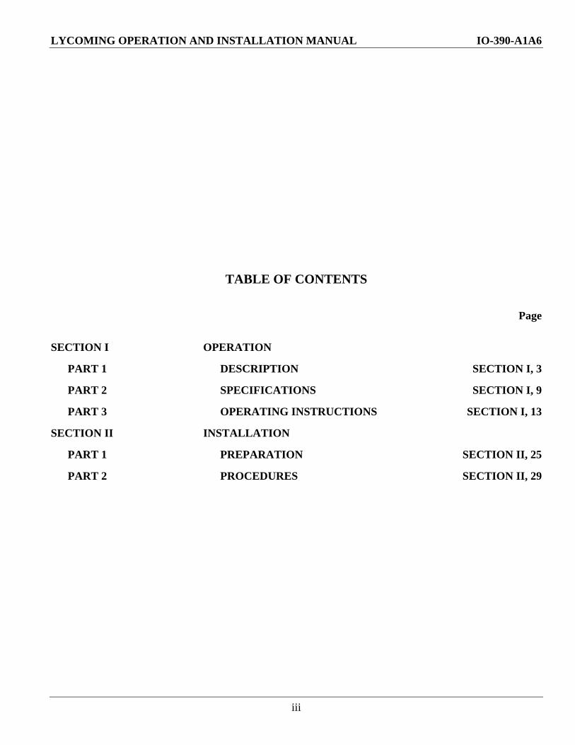
TABLE OF CONTENTS
Page
SECTION I OPERATION
PART 1 DESCRIPTION SECTION I, 3
PART 2 SPECIFICATIONS SECTION I, 9
PART 3 OPERATING INSTRUCTIONS SECTION I, 13
SECTION II INSTALLATION
PART 1 PREPARATION SECTION II, 25
PART 2 PROCEDURES SECTION II, 29

IO-390-A1A6 LYCOMING OPERATION AND INSTALLATION MANUAL
iv
This Page Intentionally Left Blank.

LYCOMING OPERATION AND INSTALLATION MANUAL SECTION I IO-390-A1A6 DESCRIPTION
1
SECTION I
PART 1 DESCRIPTION
Page
General .............................................................................................................................................................3
Cylinders...........................................................................................................................................................3
Valve Operating Mechanism .........................................................................................................................3
Crankcase ........................................................................................................................................................3
Crankshaft .......................................................................................................................................................3
Accessory Housing ..........................................................................................................................................3
Connecting Rods ..............................................................................................................................................4
Pistons ..............................................................................................................................................................4
Oil Sump ...........................................................................................................................................................4
Cooling System ................................................................................................................................................4
Induction System .............................................................................................................................................4
Lubrication System..........................................................................................................................................5
SECTION I LYCOMING OPERATION AND INSTALLATION MANUAL DESCRIPTION IO-390-A1A6
2
This Page Intentionally Left Blank.

LYCOMING OPERATION AND INSTALLATION MANUAL SECTION I IO390A SERIES DESCRIPTION
3 Revised June 2009 – 60297341
SECTION I
PART 1 DESCRIPTION
The Lycoming IO390A Series engine is a fuel injected, directdrive, fourcylinder, horizontally opposed, and aircooled with a down exhaust. This engine is supplied with a starter. Mounting pad drives for two ANtype accessories and a propeller governor are included.
FAA Type Certificate Number E00006NY has been issued for this engine.
The IO390A Series engine has a rated maximum continuous power of 210 hp at 2700 RPM at standard sea level conditions. The engine has a bore of 5.319 in., a stroke of 4.375 in., a piston displacement of 389 cubic inches, and a compression ratio of 8.9:1.
Cylinders The nitrided cylinders are aircooled with the major parts (head and barrel) screwed and shrunk together. The heads are made from an aluminum alloy casting with a fully machined combustion chamber. Valve guides and valve seats are shrunk into machined recesses in the head. Rocker shaft bearing supports are cast integrally with the head along with the housings to form the rocker boxes for both intake and exhaust valve rockers.
The Lycoming IO390A Series engine incorporates a color coding system painted on the cylinder heads to designate the specific cylinder barrels and spark plugs required. The IO390A Series engine has nitrided cylinders, indicated by blue paint between the shroud tubes, and requires longreach spark plugs, indicated by yellow paint between the spark plug and the rocker box cover.
Cylinder barrels are machined from a chrome nickel molybdenum steel forging with deep integral cooling fins. The interiors of the barrels are ground and honed to a specified finish.
Valve Operating Mechanism The valveoperating mechanism employs a conventional camshaft located above and parallel to the crankshaft. The camshaft actuates tappets which operate the valves through push rods and valve rockers.
Roller tappets are used to compensate for any expansion or contraction occurring in the valve train.
Crankcase The crankcase assembly consists of two reinforced aluminum alloy castings divided at the centerline of the engine and fastened together by a series of body fit through studs and bolts and nuts. The mating surfaces of the two castings are joined without use of a gasket, and the main bearing bores are machined for the use of precisiontype main bearing inserts. The crankcase forms the bearings for the camshaft.
Crankshaft The crankshaft is made from a chrome nickel molybdenum steel forging and all journal surfaces are nitrided. A system of dynamic counterweights eliminates torsional vibration.
Accessory Housing An accessory housing is machined from an aluminum alloy casting and is fastened to the rear of the crankcase and to the top of the oil sump. The two magnetos and the geardriven fuel pump are mounted on machined pads on the accessory housing, and provisions for two additional accessories are provided.
SECTION I LYCOMING OPERATION AND INSTALLATION MANUAL DESCRIPTION IO390A SERIES
60297341 Revised June 2009 4
Connecting Rods Connecting rods are made in the form of “H” sections from alloy steel forgings. They have replaceable bearing inserts in the crankshaft ends and splittype bronze bushings in the piston ends. The bearing caps on the crankshaft ends of the rods are retained by two bolts through each cap secured by nuts.
Pistons The pistons are machined from an aluminum alloy forging. The piston pin is of the fullfloating type with a plug at each end of the pin.
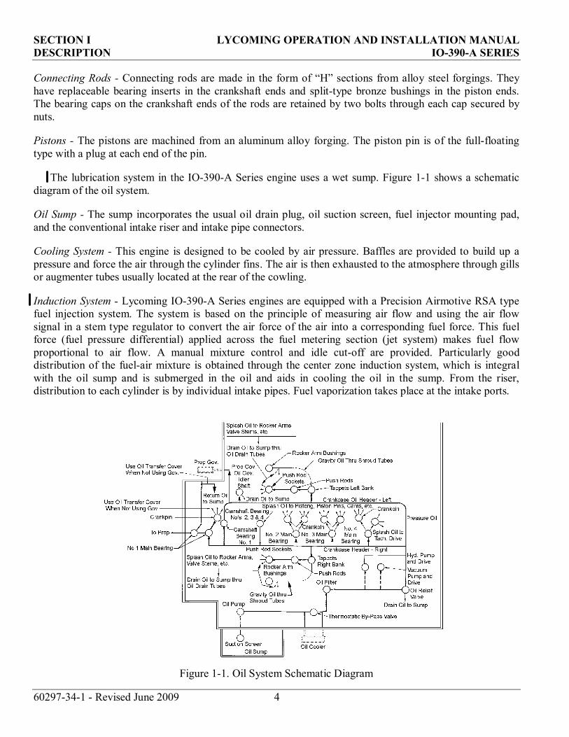
The lubrication system in the IO390A Series engine uses a wet sump. Figure 11 shows a schematic diagram of the oil system.
Oil Sump The sump incorporates the usual oil drain plug, oil suction screen, fuel injector mounting pad, and the conventional intake riser and intake pipe connectors.
Cooling System This engine is designed to be cooled by air pressure. Baffles are provided to build up a pressure and force the air through the cylinder fins. The air is then exhausted to the atmosphere through gills or augmenter tubes usually located at the rear of the cowling.
Induction System Lycoming IO390A Series engines are equipped with a Precision Airmotive RSA type fuel injection system. The system is based on the principle of measuring air flow and using the air flow signal in a stem type regulator to convert the air force of the air into a corresponding fuel force. This fuel force (fuel pressure differential) applied across the fuel metering section (jet system) makes fuel flow proportional to air flow. A manual mixture control and idle cutoff are provided. Particularly good distribution of the fuelair mixture is obtained through the center zone induction system, which is integral with the oil sump and is submerged in the oil and aids in cooling the oil in the sump. From the riser, distribution to each cylinder is by individual intake pipes. Fuel vaporization takes place at the intake ports.
Figure 11. Oil System Schematic Diagram

LYCOMING OPERATION AND INSTALLATION MANUAL SECTION I IO-390-A1A6 DESCRIPTION
5
Lubrication System - The lubrication system is of the pressure wet sump type. Figure 1-1 shows a schematic diagram of the oil system. The main bearings, connecting rod bearings, camshaft bearings, valve tappets, push rods and crankshaft idle gears are lubricated by means of oil collectors and spray. The oil pump, which is located in the accessory housing, draws oil through a drilled passage leading from the oil suction screen located in the sump. The oil from the pump then enters a drilled passage in the accessory housing, where a flexible line leads the oil to the external oil cooler. In the event that cold oil or an obstruction should restrict the flow of oil to the cooler, an oil cooler bypass valve is provided. Pressure oil from the cooler returns to a second threaded connection on the accessory housing from which point a drilled passage conducts the oil to the oil pressure screen, which is installed in a cast chamber located on the accessory housing below the tachometer drive.
The oil pressure screen is provided to filter from the oil any solid particles that may have passed through the suction screen in the sump. After being filtered in the pressure screen chamber, the oil is fed through a drilled passage to the oil relief valve, located in the upper right side of the crankcase in the front of the accessory housing.
This relief valve regulates the engine oil pressure by allowing excessive oil to return to the sump, while the balance of the pressure oil is fed to the main oil gallery, the oil is distributed by means of separate drilled passages to the main bearings of the rod journals. Oil from the main oil gallery also flows to the cam and the valve gear passages, and is then conducted through branch passages to the roller tappets and camshaft bearings. Oil enters the tappet through indexing holes and travels out through the hollow push rods to the valve mechanism, lubricating the valve rocker bearings and the valve stems. Residual oil from the bearings, accessory drives and the rocker boxes is returned by gravity to the sump.
The fuel injection systems control fuel flow in proportion to airflow with injection.
Dual ignition is furnished by two Slick magnetos and harnesses.

SECTION 1 LYCOMING OPERATION AND INSTALLATION MANUAL DESCRIPTION IO-390-A1A6
6
This Page Intentionally Left Blank.
LYCOMING OPERATION AND INSTALLATION MANUAL SECTION I IO-390-A1A6 SPECIFICATIONS
7
SECTION I
PART 2 SPECIFICATIONS
Page
Specifications ....................................................................................................................................................9
Standard Engine Weights ..............................................................................................................................9
Moments of Inertia ..........................................................................................................................................9
Accessory Drives .............................................................................................................................................9
SECTION I LYCOMING OPERATION AND INSTALLATION MANUAL SPECIFICATIONS IO-390-A1A6
8
This Page Intentionally Left Blank.
LYCOMING OPERATION AND INSTALLATION MANUAL SECTION I IO390A SERIES SPECIFICATIONS
9 Revised June 2009 60297341
SECTION I
PART 2 SPECIFICATIONS
1. SPECIFICATIONS.
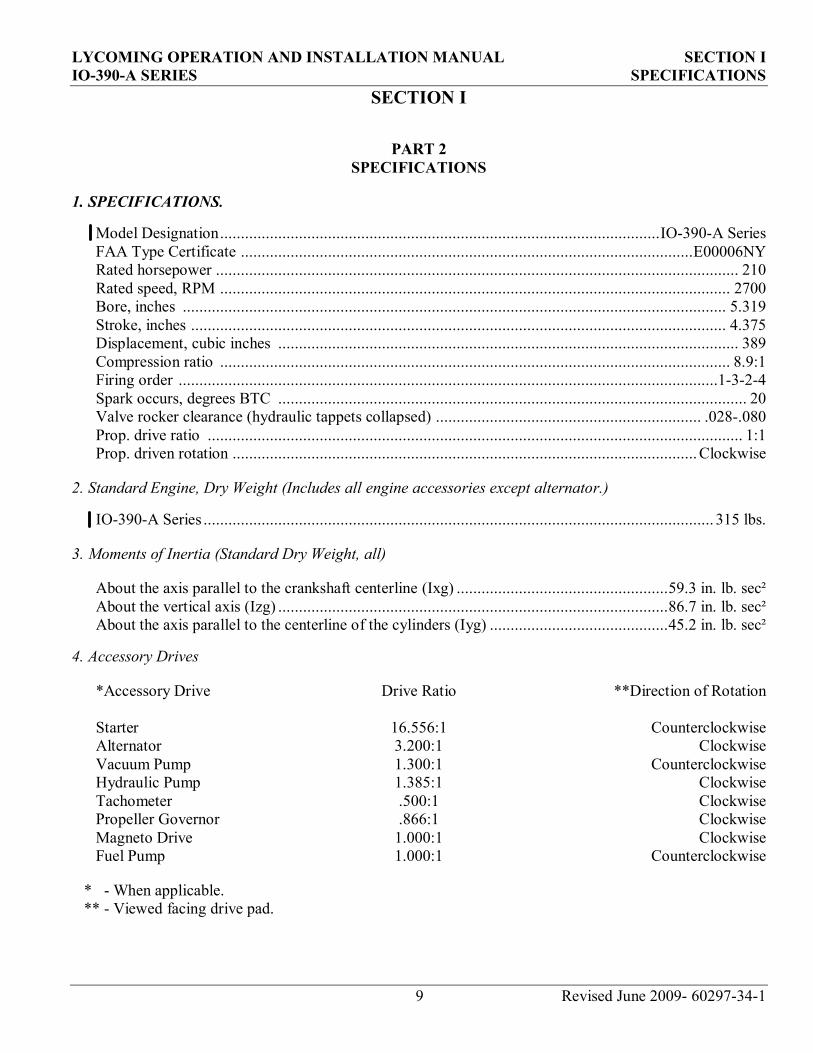
Model Designation..........................................................................................................IO390A Series FAA Type Certificate .............................................................................................................E00006NY Rated horsepower .............................................................................................................................. 210 Rated speed, RPM ........................................................................................................................... 2700 Bore, inches ................................................................................................................................... 5.319 Stroke, inches ................................................................................................................................. 4.375 Displacement, cubic inches ............................................................................................................... 389 Compression ratio ........................................................................................................................... 8.9:1 Firing order ..................................................................................................................................1324 Spark occurs, degrees BTC ................................................................................................................. 20 Valve rocker clearance (hydraulic tappets collapsed) ................................................................ .028.080 Prop. drive ratio ................................................................................................................................. 1:1 Prop. driven rotation ................................................................................................................Clockwise
2. Standard Engine, Dry Weight (Includes all engine accessories except alternator.)
IO390A Series ........................................................................................................................... 315 lbs.
3. Moments of Inertia (Standard Dry Weight, all)
About the axis parallel to the crankshaft centerline (Ixg) ...................................................59.3 in. lb. sec² About the vertical axis (Izg) ..............................................................................................86.7 in. lb. sec² About the axis parallel to the centerline of the cylinders (Iyg) ...........................................45.2 in. lb. sec²
4. Accessory Drives
*Accessory Drive Drive Ratio **Direction of Rotation
Starter 16.556:1 Counterclockwise Alternator 3.200:1 Clockwise Vacuum Pump 1.300:1 Counterclockwise Hydraulic Pump 1.385:1 Clockwise Tachometer .500:1 Clockwise Propeller Governor .866:1 Clockwise Magneto Drive 1.000:1 Clockwise Fuel Pump 1.000:1 Counterclockwise
* When applicable.** Viewed facing drive pad.

SECTION I LYCOMING OPERATION AND INSTALLATION MANUAL SPECIFICATIONS IO-390-A1A6
10
This Page Intentionally Left Blank.
LYCOMING OPERATION AND INSTALLATION MANUAL SECTION I IO-390-A1A6 OPERATING INSTRUCTIONS
11
SECTION I
PART 3 OPERATING INSTRUCTIONS
Page
General ...........................................................................................................................................................13
Prestarting Items of Maintenance ...............................................................................................................13
Starting Procedures ......................................................................................................................................14
Cold Weather Starting .................................................................................................................................15
Ground Running and Warm-Up .................................................................................................................15
Ground Check ...............................................................................................................................................15
Operating in Flight .......................................................................................................................................16
Fuel Mixture Leaning Procedure ................................................................................................................16
Engine Flight Chart ......................................................................................................................................17
Engine Shut Down ........................................................................................................................................19
Performance Curves .....................................................................................................................................20

SECTION I LYCOMING OPERATION AND INSTALLATION MANUAL OPERATING INSTRUCTIONS IO-390-A1A6
12
This Page Intentionally Left Blank.

LYCOMING OPERATION AND INSTALLATION MANUAL SECTION I IO-390-A1A6 OPERATING INSTRUCTIONS
13
SECTION I
PART 3 OPERATING INSTRUCTIONS
1. GENERAL.
Close adherence to these instructions will greatly contribute to the long life, economy and satisfactoryoperation of the engine.
NOTE
YOUR ATTENTION IS DIRECTED TO THE WARRANTIES THAT APPEAR IN THE FRONT OF THIS MANUAL REGARDING ENGINE SPEED, THE USE OF SPECIFIED FUELS AND LUBRICANTS, REPAIRS AND ALTERATIONS. PERHAPS NO OTHER ITEM OF ENGINE OPERATION AND MAINTENANCE CONTRIBUTES QUITE SO MUCH TO SATISFACTORY PERFORMANCE AND LONG LIFE AS THE CONSTANT USE OF CORRECT GRADES OF FUEL AND OIL, CORRECT ENGINE TIMING, AND FLYING THE AIRCRAFT AT ALL TIMES WITHIN THE SPEED AND POWER RANGE SPECIFIED FOR THE ENGINE. DO NOT FORGET THAT VIOLATION OF THE OPERATION AND MAINTENANCE SPECIFICATIONS FOR YOUR ENGINE WILL NOT ONLY VOID YOUR WARRANTY BUT WILL SHORTEN THE LIFE OF YOUR ENGINE AFTER ITS WARRANTY PERIOD HAS PASSED.
New engines have been carefully run-in by Lycoming and therefore, no further break-in is necessary insofar as operation is concerned; however, operate new or newly overhauled engines using only the recommended lubricating oils. Refer to Oil Requirements, Section 8.d.
NOTE
Cruise at 65% to 75% power until a total of 50 hours has been accumulated or the oil consumption has stabilized. This is to insure the proper seating of the rings as is applicable to new engines and engines in service following cylinder replacement or top overhaul of one or more cylinders.
The minimum fuel octane rating is listed in the flight chart, Part 9 of this section. Do not use fuel of a lower octane rating or automotive fuel (regardless of octane rating).
2. PRESTARTING ITEMS OF MAINTENANCE.
Before starting the aircraft engines for the first flight of the day, perform the following items ofmaintenance inspection in conjunction with the aircraft Pilot’s Operating Handbook preflight check.
(a) Be sure all switches are in the “Off” position.
(b) Be sure magneto ground wires are connected.
(c) Check oil level.
SECTION I LYCOMING OPERATION AND INSTALLATION MANUAL OPERATING INSTRUCTIONS IO-390-A1A6
14
(d) Check fuel level.
(e) Check fuel and oil line connections, note minor indications for repair at 50 hour inspection. Repair any leaks before aircraft is flown.
(f) Open the fuel drain to remove any accumulation of water and sediment.
(g) Make sure all shields and cowling are in place and secure. If any are missing or damaged, repair or replacement should be made before the aircraft is flown.
(h) Check engine controls for general condition, travel and freedom of operation.
(i) Inspect and service induction system air filter in accordance with the airframe manufacturer’s recommendations.
3. STARTING PROCEDURES.
The following starting procedures are recommended; however, the starting characteristics of various installations will necessitate some variation from these procedures.
NOTE
Limit cranking periods to ten (10) to twelve (12) seconds with 5 minutes rest between cranking periods.
(a) Cold Engine.
(1) Perform pre-flight inspection.
(2) Set propeller governor in “Full RPM”.
(3) Turn fuel valve to “on” position.
(4) Turn boost pump on and move mixture control to “Full Rich” position until a slight but steady flow is indicated.
(5) Return mixture control to “Idle Cut-Off” position.
(6) Set magneto selector switch. Consult aircraft manufacturer’s handbook for correct position.
(7) Engage starter.
(8) When engine starts, place magneto selector switch in “Both” position.
(9) Move mixture control slowly and smoothly to “Full Rich”.
(10) Check oil pressure gage for indicated pressure. If oil pressure is not indicated within thirty seconds, stop the engine and determine trouble.
LYCOMING OPERATION AND INSTALLATION MANUAL SECTION I IO-390-A1A6 OPERATING INSTRUCTIONS
15
NOTE
If engine fails to achieve a normal start, assume it to be flooded. Crank engine over with throttle wide open and ignition off. Then repeat above procedure.
Hot Engine - Because fuel percolates, the system must be cleared of vapor; it is recommended that the same procedure, as outlined above be used for starting a hot engine.
4. COLD WEATHER STARTING.
During extreme cold weather, it may be necessary to preheat the engine and oil before starting.
5. GROUND RUNNING AND WARM-UP.
Subject engines are air pressure cooled and depend on the forward movement of the aircraft to maintain proper cooling. Particular care is necessary, therefore, when operating these engines on the ground. To prevent overheating, it is recommended that the following precautions be observed.
NOTE
Any ground check that requires full throttle operation must be limited to three minutes, or less if indicated cylinder head temperature exceeds the maximum stated in this manual.
(a) Head the aircraft into the wind.
(b) Leave mixture in “Full Rich”.
(c) Operate the engine on the ground only with the propeller in minimum blade angle setting.
(d) Warm up at approximately 1000-1200 RPM. Avoid prolonged idling and do not exceed 2200 RPM on the ground.
(e) Engine is warm enough for take-off when the throttle can be opened without the engine faltering.
6. GROUND CHECK.
(a) Warm up as directed above.
(b) Check both oil pressure and oil temperature.
(c) Leave mixture in “Full Rich”.
(d) (Where applicable) Move the propeller control through its complete range to check operation andreturn to full low pitch position. Full feathering check (twin engine) on the ground is not recommended but the feathering action can be checked by running the engine between 1000-1500 RPM; then momentarily pulling the propeller control into the feathering position. Do not allow the RPM to drop more than 500 RPM.

SECTION I LYCOMING OPERATION AND INSTALLATION MANUAL OPERATING INSTRUCTIONS IO-390-A1A6
16
(e) A proper magneto check is important. Additional factors, other than the ignition system, affect magneto drop-off. They are load-power output, propeller pitch and mixture strength. The important thing is that the engine runs smoothly because magneto drop-off is affected by the variables listed above. Make the magneto check in accordance with the following procedures.
(1) (Controllable Pitch Propeller) With propeller in minimum pitch angle, set the engine to produce 50-65% power as indicated by the manifold pressure gage. Mixture control should be in the full rich position. At these settings, the ignition system and spark plugs must work harder because of the greater pressure within the cylinders. Under these conditions, ignition problems can occur. Mag checks at low power settings will only indicate fuel-air distribution quality.
NOTE
Aircraft that are equipped with fixed pitch propellers, or not equipped with manifold pressure gage, may check magneto drop-off with engine operating at approximately 2100-2200 RPM.
(2) Switch from both magnetos to one and note drop-off; return to both until engine regains speed and switch to the other magneto and note drop-off, then return to both. Drop-off must not exceed 175 RPM and must not exceed 50 RPM between magnetos. A smooth drop-off past normal is usually a sign of a too lean or too rich mixture.
(f) Do not operate on a single magneto for too long a period; a few seconds is usually sufficient to check drop-off and will minimize plug fouling.
7. OPERATING IN FLIGHT.
(a) Subject engines are equipped with a dynamic counterweight system and must be operated accordingly. Use a smooth, steady movement (avoid rapid opening and closing) of the throttle.
(b) See airframe manufacturer’s instructions for recommended power settings.
8. FUEL MIXTURE LEANING PROCEDURE.
Improper fuel/air mixture during flight is responsible for many engine problems, particularly during take-off and climb power settings. The procedures described in this manual provide proper fuel/air mixture when leaning Lycoming engines; they have proven to be both economical and practical by eliminating excessive fuel consumption and reducing damaged parts replacement. It is therefore recommended that operators, of all Lycoming aircraft power-plants, utilize the instructions in this publication any time the fuel/air mixture is adjusted during flight.
Manual leaning may be monitored by exhaust gas temperature indication, fuel flow indication, and by observation of engine speed and/or airspeed. However, whatever instruments are used in leaning the mixture, observe the following general rules.
GENERAL LEANING RULES
Never exceed the maximum red line cylinder head temperature limit.

LYCOMING OPERATION AND INSTALLATION MANUAL SECTION I IO-390-A1A6 OPERATING INSTRUCTIONS
17
For maximum service life, cylinder head temperatures must be maintained below 435°F. (224°C.) during high performance cruise operation and below 400°F. (205°C.) for economy cruise powers.
On engines with manual mixture control, maintain mixture control in “Full Rich” position for rated take-off, climb and maximum cruise powers (above approximately 75%). However, during take-off from high elevation airport or during climb, roughness or loss of power may result from over-richness. In such a case adjust mixture control only enough to obtain smooth operation - not for economy. Observe instruments for temperature rise. Rough operation due to over-rich fuel/air mixture is most likely to be encountered at altitudes above 5,000 feet.
Always return the mixture to full rich before increasing power settings.
Operate the engine at maximum power mixture for performance cruise powers and at best economy mixture for economy cruise power; unless otherwise specified in the airplane owners manual.
During let-down flight operations it may be necessary to manually lean carbureted or fuel injected engines to obtain smooth operation.
(a) Leaning to Exhaust Gas Temperature. (Normally aspirated engines with fuel injectors or carburetors)
(1) Maximum Power Cruise (approximately 75% power) - Never lean beyond 150°F. on rich side of peak EGT unless aircraft operator’s manual shows otherwise. Monitor cylinder head temperatures.
(2) Best Economy Cruise (approximately 75% power and below) - Operate at peak EGT.
(b) Leaning to Flowmeter.
Lean to applicable fuel-flow tables or lean to indicator marked for correct fuel-flow for each power setting.
9. ENGINE FLIGHT CHART.T
(a) Fuel Requirements.
100 or 100LL Octane, Minimum Aviation Grade Fuel
(b) Fuel Pressure, psi -
Min. Max.
Inlet to fuel pump -2 35 Inlet to fuel injector 14 45

SECTION I LYCOMING OPERATION AND INSTALLATION MANUAL OPERATING INSTRUCTIONS IO390A SERIES
60297341 Revised June 2009 18
(c) Oil Requirements
*Recommended Grade Oil
Average Ambient Air
MILL6082B or SAEJ1966 Spec. Mineral Grades
MILL22851 or SAEJ1899 Spec. Ashless Dispersant
Grades
All Temperatures SAE15W50 or SAE20W50 Above 80°F SAE60 SAE60 Above 60°F SAE50 SAE40 or SAE50 30°F to 90°F SAE40 SAE40 0°F to 70°F SAE30 SAE40, SAE30, SAE20W40 Below 10°F SAE20 SAE30 or SAE20W30
* In new, newly overhauled, or rebuilt engines or following the replacement of one or more cylinders, use only mineral oil during the first 50 hours of operation.
(d) Oil Sump Capacity
IO390A Series ............................................................................................................... 8 U.S. Qts. (Minimum safe quantity in sump) ................................................................................ 2 U.S. Qts.
(e) Oil Pressure, psi
Maximum Minimum Idling Start and Warmup
Normal Operation 95 55 25 115
(f) Oil Temperature: The maximum permissible oil temperature is 235°F. (113°C.). For maximum engine life, maintain desired oil temperature is 180°F (82.22°C).
(g) Fuel and Oil Consumption
Operation RPM HP
Fuel Cons. Gal./Hr.
Max. Oil Cons. Qts./Hr.
*Max. Cyl. Head Temp.
Normal Rated 2700 210 1.0 475°F (246°C) Performance Cruise (75% Rated) 2450 158 12.3 0.75 475°F (246°C) Economy Cruise (65% Rated) 2350 137 9.1 0.60 475°F (246°C)
* At Bayonet Location For maximum service life of the engine maintain cylinder head temperatures between 150°F. and 435°F. during continuous operation.
LYCOMING OPERATION AND INSTALLATION MANUAL SECTION I IO-390-A1A6 OPERATING INSTRUCTIONS
19
10. ENGINE SHUT DOWN.
(a) Set propeller at minimum blade angle.
(b) Idle until there is a decided decrease in cylinder head temperature.
(c) Move mixture control to “Idle Cut-Off”.
(d) When engine stops, turn ignition switch off.
SECTION I LYCOMING OPERATION AND INSTALLATION MANUAL OPERATING INSTRUCTIONS IO-390-A1A6
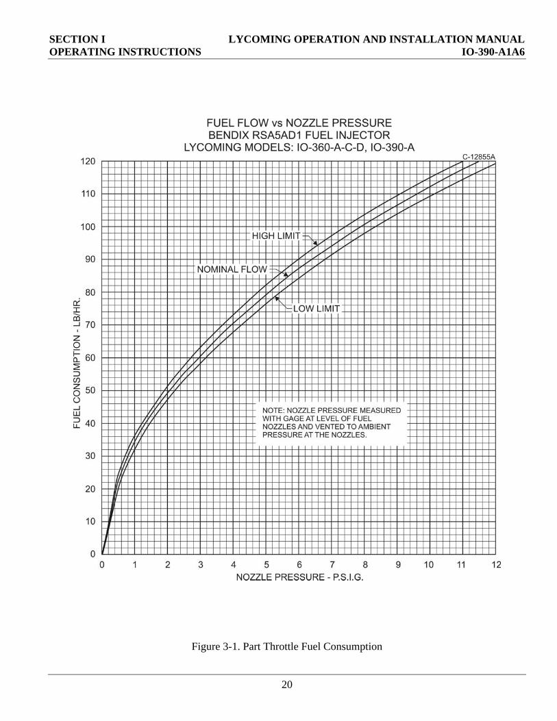
Figure 3-1. Part Throttle Fuel Consumption
20
LYCOMING OPERATION AND INSTALLATION MANUAL SECTION I IO-390-A1A6 OPERATING INSTRUCTIONS
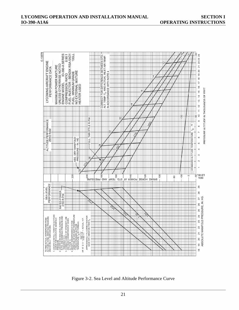
Figure 3-2. Sea Level and Altitude Performance Curve
21

SECTION I LYCOMING OPERATION AND INSTALLATION MANUAL OPERATING INSTRUCTIONS IO-390-A1A6
Figure 3-3. Minimum Fuel Flow vs. Power
22
LYCOMING OPERATION AND INSTALLATION MANUAL SECTION II IO-390-A1A6 PREPARATION
23
SECTION II
PART 1 PREPARATION
Page
Preparation of Engine for Installation ........................................................................................................25
Uncrating.....................................................................................................................................................25
Uninhibiting ................................................................................................................................................25
Preparation of Fuel Injector .........................................................................................................................26

SECTION II LYCOMING OPERATION AND INSTALLATION MANUAL PREPARATION IO-390-A1A6
24
This Page Intentionally Left Blank

LYCOMING OPERATION AND INSTALLATION MANUAL SECTION II IO390A SERIES PREPARATION
25 Revised June 2009 – 60297341
SECTION II PART 1
PREPARATION OF ENGINE FOR INSTALLATION
Each Lycoming engine undergoes a thorough preservative treatment before leaving the factory. To protect the cylinders and related parts, preservative oil is sprayed into each cylinder. Careful uncrating and uninhibiting of the engine is very important to prevent any of the preservative oil from entering the induction system.
1. UNCRATING.
The Lycoming IO390A Series engine has been carefully packed for shipment to prevent damage in transit and to ensure that the engine reaches its destination in perfect condition.
NOTE
Any engine that has been stored in a cold area must be brought into an area with a temperature of at least 70°F (21°C) for 24 hours before uncrating. If this is not possible, the preservative oil in the engine must be warmed to facilitate draining by heating the cylinders with heat lamps.
a. Remove the top of the crate and set it aside.
b. Lift and set aside any packing materials from on top of the engine.
c. Connect an engine lifting cable to a winch, hoist, or crane able to support a minimum load of 750 lbs.
d. Connect the engine lifting cable to the lifting lugs on the top of the engine.
e. Lift the engine from the crate.
2. UNIHIBITING ENGINE.
CAUTION
Do not rotate the crankshaft of an engine containing preservative oil before removing the bottom spark plugs. Engine damage will result.
CAUTION
Avoid contact of preservation oil with painted surfaces. If preservation oil does contact a painted surface, clean it off with a solvent as soon as possible.
a. Remove all the bottom spark plugs.

SECTION II LYCOMING OPERATION AND INSTALLATION MANUAL PREPARATION IO390A SERIES
60297341 Revised June 2009 26
b. Turn the crankshaft three or four revolutions by hand.
c. Tilt the engine to one side until the spark plug holes on that side are oriented vertically.
d. Rotate the crankshaft at least two revolutions and allow the oil to drain out through the spark plug holes.
e. Repeat steps (3) and (4) for the opposite side of the engine.
f. Inspect the spark plugs before reinstalling them. If they are not clean, wash them in clean oilbased solvent. Dry them with compressed air.
g. Remove the oil sump plug and allow any preservative oil that has accumulated in the sump to drain.
h. Remove the oil screen and clean it with a hydrocarbonbased solvent such as Varsol or equivalent.
i. Reinstall the oil screen.
j. If a constant speed propeller is to be used, the expansion plug must be removed from the crankshaft. Pierce a 1/8 in. to 3/16 in. hole in the center of the plug to remove it.
k. Replace the oil sump plug and install a safety wire. Refer to Maintenance and Overhaul Manual P/N LMOIO390A Series for lockwire information.
l. Fill the sump with 8 quarts of aviationgrade oil. Refer to Section I, Part 2 for oil recommendations.
m. Inspect the induction riser to ensure that it is clean and dry. If a significant amount of preservative oil is noted, clean, reinspect, and reinstall the intake pipes.
3. PREPARATION OF FUEL INJECTOR.
a. Remove the fuel inlet strainer and clean it with a hydrocarbonbased solvent such as Varsol or equivalent.
b. Inspect the fuel supply lines, fuel manifold, throttle body, and “bullet nose” venturi to ensure they are clean and dry.
c. Reassemble the injector. Inject clean fuel into the fuel inlet connection with the fuel outlets uncapped until clean fuel flows from the outlets. Do not exceed 15 psi inlet pressure.
CAUTION
Dispose of used engine preservative and solvents in accordance with all applicable federal, state, and local environmental regulations.
NOTE
If a small amount of preservative oil remains in the engine, it will not be harmful; however, during the first oil change, the oil should be drained while the engine is hot. This will remove any residual preservative oil.

LYCOMING OPERATION AND INSTALLATION MANUAL SECTION II IO-390-A1A6 PROCEDURES
27
SECTION II
PART 2 PROCEDURES
Page
Installing Engine ............................................................................................................................................29
Connecting External Accessories..................................................................................................................29
Pre-Oiling Engine Prior to Start ..................................................................................................................33

SECTION II LYCOMING OPERATION AND INSTALLATION MANUAL PROCEDURES IO-390-A1A6
28
This Page Intentionally Left Blank.
LYCOMING OPERATION AND INSTALLATION MANUAL SECTION II IO390A SERIES PROCEDURES
29 Revised June 2009 – 60297341
SECTION II
PART 2 PROCEDURES
1. INSTALLING ENGINE.
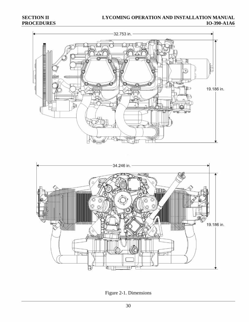
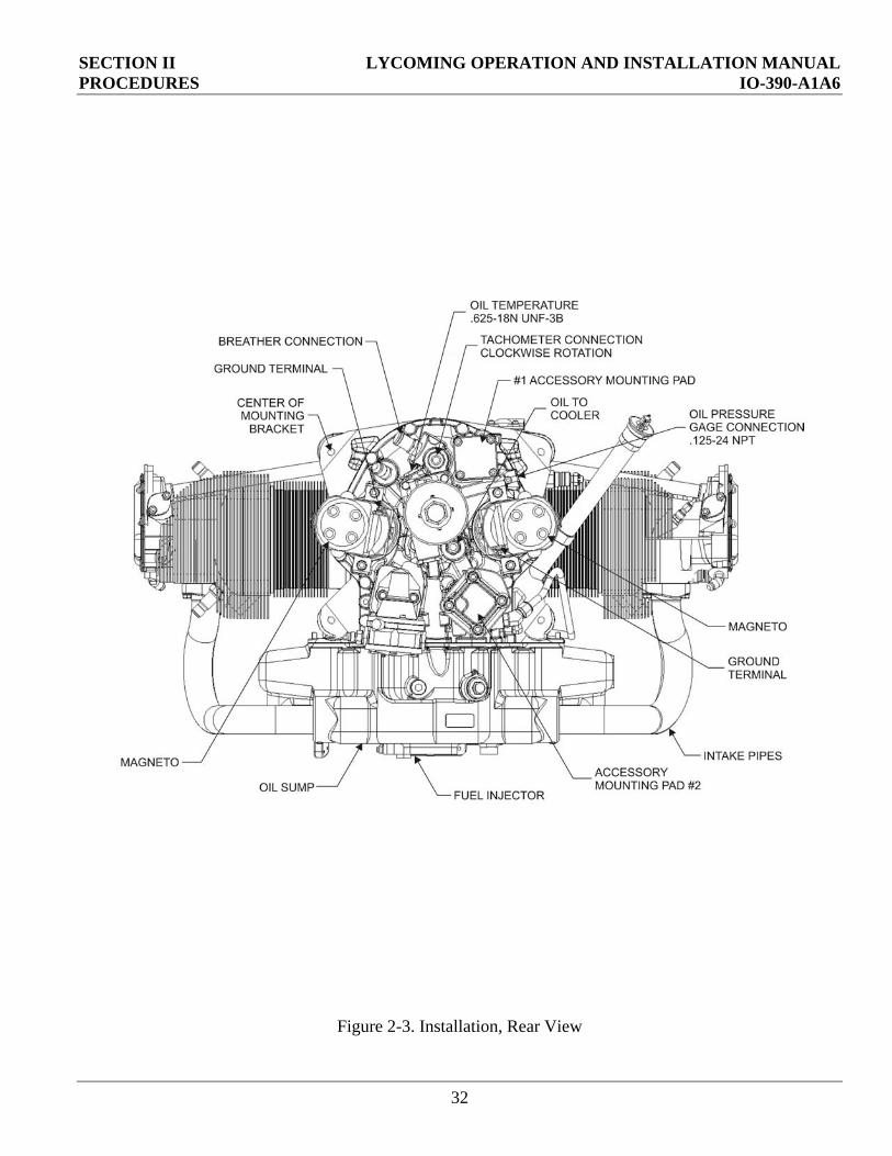
a. Refer to Figures 21 through 23 for dimensions and connection locations.
b. If the engine is to be installed in an airframe from which an engine has previously been removed, inspect the engine mounts to ensure they are not bent, misaligned, distorted, or damaged.
CAUTION
Distorted, misaligned, bent, or damaged engine mounts may cause engine or airframe damage or engine failure.
c. Refer to the airframe manufacturer’s instructions for attaching the engine to the engine mounts.
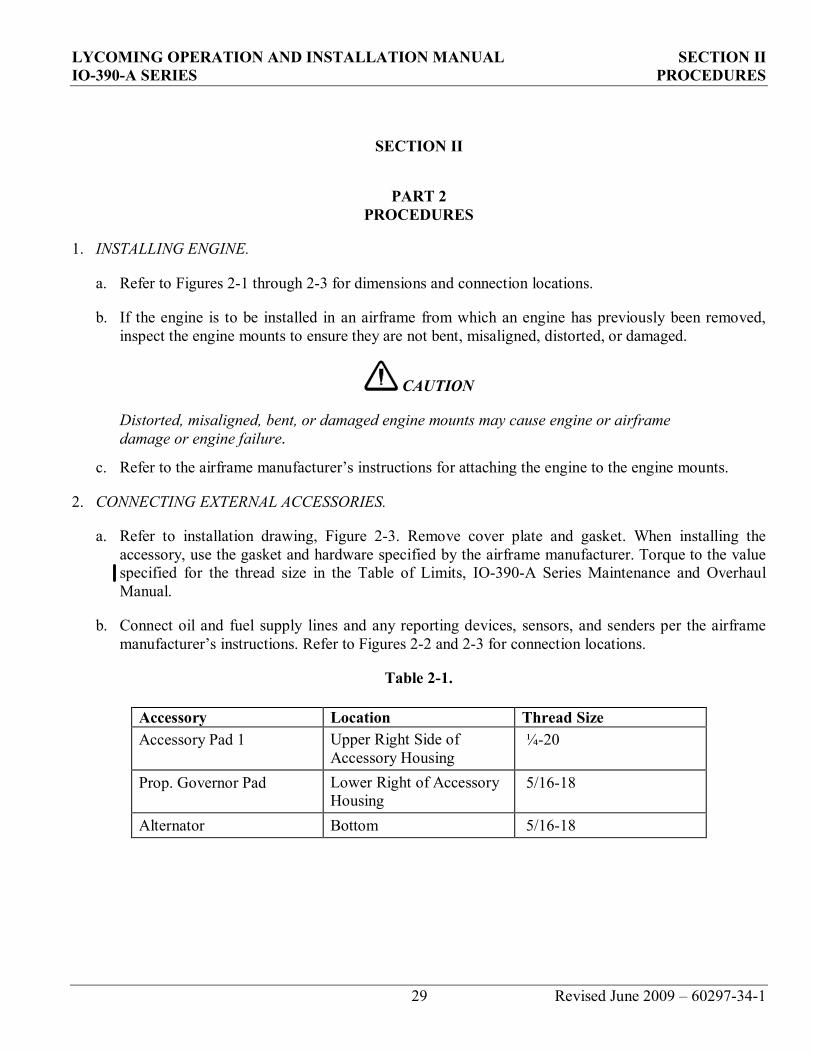
2. CONNECTING EXTERNAL ACCESSORIES.
a. Refer to installation drawing, Figure 23. Remove cover plate and gasket. When installing the accessory, use the gasket and hardware specified by the airframe manufacturer. Torque to the value specified for the thread size in the Table of Limits, IO390A Series Maintenance and Overhaul Manual.
b. Connect oil and fuel supply lines and any reporting devices, sensors, and senders per the airframe manufacturer’s instructions. Refer to Figures 22 and 23 for connection locations.
Table 21.
Accessory Location Thread Size Accessory Pad 1 Upper Right Side of
Accessory Housing ¼20
Prop. Governor Pad Lower Right of Accessory Housing
5/1618
Alternator Bottom 5/1618
SECTION II LYCOMING OPERATION AND INSTALLATION MANUAL PROCEDURES IO-390-A1A6
Figure 2-1. Dimensions
30

LYCOMING OPERATION AND INSTALLATION MANUAL SECTION II IO-390-A1A6 PROCEDURES
Figure 2-2. Installation, Left Side View
31
SECTION II LYCOMING OPERATION AND INSTALLATION MANUAL PROCEDURES IO-390-A1A6
Figure 2-3. Installation, Rear View
32
LYCOMING OPERATION AND INSTALLATION MANUAL SECTION II IO-390-A1A6 PROCEDURES
3. PRE-OILING ENGINE PRIOR TO START.
CAUTION To eliminate the possibility of high-speed bearing failure resulting from insufficient lubrication during initial starts, all aircraft engines must be pre-oiled after an overhaul, following oil cooler draining or replacement, or whenever the oil lines have been disconnected.
WARNING
If a propeller is installed, remain clear of the propeller turning arc. The propeller will turn during this procedure, and could cause injury.
a. Fill the oil cooler with oil.
b. Remove one spark plug from each cylinder of the engine.
c. If the aircraft is not equipped with an oil pressure gage, remove the STD-1102 allen plug from the upper left front of the main galley, aft of the propeller governor pad.
d. Place the mixture control lever in the “IDLE CUT-OFF” position and the fuel selector switch in the “OFF” position.
e. Turn the engine with the starter (or with an external power source, if available) until a minimum oil pressure of 20 lb. is indicated on the oil pressure gage or until there is a steady flow of oil from the opening on the engine.
CAUTION
Do not energize the starter for periods longer than 15 seconds. Allow the starter to cool after each energizing period. Refer to the starter manufacturer’s instruction manual for additional information.
NOTE
If oil pressure is not determined after the first cranking of 10 to 15 seconds, allow the starter to cool and repeat the cranking/starter cooling sequence until 20 lb. is indicated on the oil pressure gage or oil flow is observed.
CAUTION
If there is no indication of steady oil pressure after five attempts, the cause should be determined and fixed
.
33
SECTION II LYCOMING OPERATION AND INSTALLATION MANUAL PROCEDURES IO-390-A1A6
34
f. Turn the starter for an additional 10 seconds to verify that the oil pressure remains at least 20 lb.
g. Reinstall the spark plugs and proceed with normal starting procedures immediately. Refer to Section I, Part 3.
h. When the engine starts, observe the oil pressure gage. If there is no oil pressure indication, shut down the engine until cause is determined.
i. Allow the engine to run for approximately 3 minutes at 1000 rpm.
j. Shut down in accordance with Section I, Part 3, Step 10.