Embed Size (px)
Citation preview

� 6 - 18 GHz FREQUENCY RANGE � COMPLEMENTARY MATCHED Rx & Tx MODULES � RF PROCESSOR & DRFM DIRECT INTERFACE � HIGH SENSITIVITY � HIGH DYNAMIC RANGE � FOR MILITARY TACTICAL ENVIRONMENT
AKON Integrated ECM Converter Subsystem with Synchronous Up/Down Frequency Conversion
INTEGRATED ECM CONVERTER SUBSYSTEM
The Tuner (down converter), Fast Stepping LO and Up Converter work as an integrated subsystem to accept the broadband RF inputs, down convert to a 1 GHz IF for use by the RF Processor and DRFM, and then re-convert the DRFM output back up to the original RF frequency. This is done synchronously by using the same LO source for both up and down conversion processes, and the same IF frequencies in both converters. Both converters incorporate digitally controlled attenuators to compress the input RF dynamic range down to 40 dB for use by the DRFM, and then to proportionally re-expand that range back in the up-converter. Both converters also incorporate high speed SDLAs so the customer has real time information on instantaneous Rx and Tx levels. The up-converter has sufficient output power to drive most HPAs be either solid state or TWT. See sections below
FEATURES:
GENERAL:
AKON’s model A20-MH251 is a critical part of our line of products which include matching receiver/tuners, fast stepping LO synthesizers, and transmit up converters for use in modern highly integrated EW/ECM systems. These subsystems are designed so that the customer can supply his own DRFM and receiver/signal processor subsystems, leveraging the customer’s internal digital processor, software and DSP capability, and allowing the simple purchase of the required microwave components to complete the ECM system.
It has been AKON’s observation that the majority of receiver/processors and DRFMs operate with RF inputs in the range of 750 MHz to 1250 MHz, 500 MHz instantaneous bandwidth. AKON has designed a line of complementary microwave subsystems to directly interface with these customer designed items.
DS308 REVF
Datasheet 308
Matched EW/ECM Subsystems6 - 18 GHz
SP2T
BPF
BPF
BPF
FIRST IF FILTER + AMPLIFIER
SECOND IF FILTER + AMPLIFIER
PRESELECTOR + LNARF INPUT6-18.0 GHz
-65 to 0 dBm
BITE TEST INPUT
FIRST IF FILTER + AMPLIFIER
OUTPUT MONITOR
RF OUTPUT6-18.0 GHz
-55 to +10 dBm BPF
BPF
BPF
POSTSELECTOR
FAST STEPPING LOSYNTHESIZER FIXED 2nd LO
SDLA
DCA
Rx VIDEO
TO RF DIGITAL PROCESSOR
TO DRFM-35 to +5 dBm
FROM DRFM-35 to +5 dBm
1.0 GHz
DCA
SDLAVIDEO
BPF
2135 Ringwood Ave. San Jose, CA 95131 Tel. (408) 432-8039 Fax (408) 432-1089www.akoninc.com [email protected]
124
6-18 GHZ TUNER SPECIFICATIONS
LIM HPF
SP3T
BPF
SDLA
RF1
RF3-65 to 0 dBm
Absorptive Switch
A1
F1
F2
F3
+22 dBm
LO-19.5–18.5 GHz
F4
4.5 GHz ±0.3 GHz
-67 to +2 dBm
A2
A3 F5
1.0 GHz ±250 MHz
Five Bits0.5 dB15.5 dB
-55 / +10
J4
9.75 – 14.25
13.75 – 18.25
5.75 – 10.25
LO-25.5 GHz
+22 dBm
Input -65 to 0T.S.S. -75 dBm(Ref. J1)
BPF
J1
RF2
SP4T
J2
J3
SP3T
J5
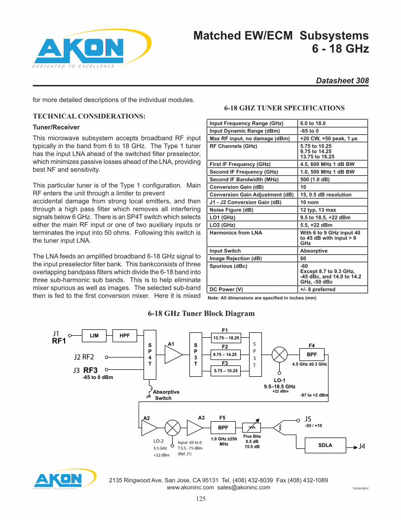
6-18 GHz Tuner Block Diagram
Input Frequency Range (GHz) 6.0 to 18.0Input Dynamic Range (dBm) -65 to 0Max RF input, no damage (dBm) +20 CW, +50 peak, 1 µsRF Channels (GHz) 5.75 to 10.25
9.75 to 14.25 13.75 to 18.25
First IF Frequency (GHz) 4.5, 600 MHz 1 dB BWSecond IF Frequency (GHz) 1.0, 500 MHz 1 dB BWSecond IF Bandwidth (MHz) 500 (1.0 dB)Conversion Gain (dB) 10Conversion Gain Adjustment (dB) 15, 0.5 dB resolutionJ1 - J2 Conversion Gain (dB) 10 nomNoise Figure (dB) 12 typ, 13 maxLO1 (GHz) 9.5 to 18.5, +22 dBmLO2 (GHz) 5.5, +22 dBmHarmonics from LNA With 6 to 9 GHz input 40
to 45 dB with input > 9 GHz
Input Switch AbsorptiveImage Rejection (dB) 60Spurious (dBc) -60
Except 8.7 to 9.3 GHz,-45 dBc, and 14.0 to 14.2GHz, -50 dBc
DC Power (V) +/- 8 preferred
Datasheet 308
Matched EW/ECM Subsystems6 - 18 GHz
for more detailed descriptions of the individual modules.
TECHNICAL CONSIDERATIONS: Tuner/ReceiverThis microwave subsystem accepts broadband RF input typically in the band from 6 to 18 GHz. The Type 1 tuner has the input LNA ahead of the switched filter preselector, which minimizes passive losses ahead of the LNA, providing best NF and sensitivity.
This particular tuner is of the Type 1 configuration. Main RF enters the unit through a limiter to prevent accidental damage from strong local emitters, and then through a high pass filter which removes all interfering signals below 6 GHz. There is an SP4T switch which selects either the main RF input or one of two auxiliary inputs or terminates the input into 50 ohms. Following this switch is the tuner input LNA.
The LNA feeds an amplified broadband 6-18 GHz signal to the input preselector filter bank. This bankconsists of three overlapping bandpass filters which divide the 6-18 band into three sub-harmonic sub bands. This is to help eliminate mixer spurious as well as images. The selected sub-band then is fed to the first conversion mixer. Here it is mixed
DS308 REVF
2135 Ringwood Ave. San Jose, CA 95131 Tel. (408) 432-8039 Fax (408) 432-1089www.akoninc.com [email protected]
125
Note: All dimensions are specified in inches (mm)
being output by the tuner.
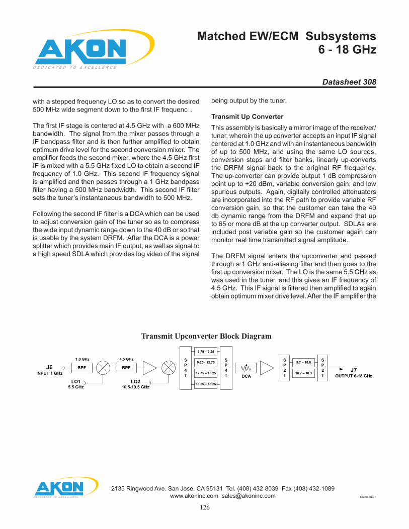
Transmit Up ConverterThis assembly is basically a mirror image of the receiver/ tuner, wherein the up converter accepts an input IF signal centered at 1.0 GHz and with an instantaneous bandwidth of up to 500 MHz, and using the same LO sources, conversion steps and filter banks, linearly up-converts the DRFM signal back to the original RF frequency. The up-converter can provide output 1 dB compression point up to +20 dBm, variable conversion gain, and low spurious outputs. Again, digitally controlled attenuators are incorporated into the RF path to provide variable RF conversion gain, so that the customer can take the 40 db dynamic range from the DRFM and expand that up to 65 or more dB at the up converter output. SDLAs are included post variable gain so the customer again can monitor real time transmitted signal amplitude.
The DRFM signal enters the upconverter and passed through a 1 GHz anti-aliasing filter and then goes to the first up conversion mixer. The LO is the same 5.5 GHz as was used in the tuner, and this gives an IF frequency of 4.5 GHz. This IF signal is filtered then amplified to again obtain optimum mixer drive level. After the IF amplifier the
Transmit Upconverter Block Diagram
with a stepped frequency LO so as to convert the desired 500 MHz wide segment down to the first IF frequenc .
The first IF stage is centered at 4.5 GHz with a 600 MHz bandwidth. The signal from the mixer passes through a IF bandpass filter and is then further amplified to obtain optimum drive level for the second conversion mixer. The amplifier feeds the second mixer, where the 4.5 GHz firstIF is mixed with a 5.5 GHz fixed LO to obtain a second IF frequency of 1.0 GHz. This second IF frequency signal is amplified and then passes through a 1 GHz bandpass filter having a 500 MHz bandwidth. This second IF filtersets the tuner’s instantaneous bandwidth to 500 MHz.
Following the second IF filter is a DCA which can be used to adjust conversion gain of the tuner so as to compress the wide input dynamic range down to the 40 dB or so that is usable by the system DRFM. After the DCA is a power splitter which provides main IF output, as well as signal to a high speed SDLA which provides log video of the signal
Datasheet 308
Matched EW/ECM Subsystems6 - 18 GHz
BPF
DCA
BPFINPUT 1 GHz
5.5 GHz 10.5-19.5 GHz
1.0 GHz 4.5 GHz SP4T
SP4T
9.25 - 12.75
12.75 – 16.25
5.75 – 9.25
16.25 – 18.25
OUTPUT 6-18 GHz
SP2T
SP2T10.7 – 18.3
5.7 – 10.8
DS308 REVF
2135 Ringwood Ave. San Jose, CA 95131 Tel. (408) 432-8039 Fax (408) 432-1089www.akoninc.com [email protected]
126

TRANSMIT UPCONVERTER SPECIFICATIONS:
FAST STEPPING SYNTHESIZED LO
Tuning of both the Tuner and Up Converter is accomplished by the third item in the set, the Fast Stepping LO. This assembly generates all necessary fixed and variable LO signals as required by both the Tuner and Up Converter. The LO Source incorporates a very stable and low phase noise TCXO as the key frequency generating element. There are then comb generators, switches, filters, mixers and amplifiers arranged so that both fixed and variable frequency outputs are available for both conversion steps in both the Tuner and Up Converter. Tuning step size can be 500 MHz (or 100 MHz) per customer requirements, and tuning speed is on the order of 70 ns. This LO puts out the fixed 5.5 GHz signal as well as the 500 MHz stepped tuning signal from 9.5 to 18.5 GHz. The LO has dual outputs for all LO frequencies to simultaneously drive one Tuner and one Up-Converter. Reference inputs can optionally be provided for phase locking the LO to an external source. An optional reference output can also be provided for
LO SPECIFICATIONS:
LO-1
LO-2
LO Block Diagram
signal is fed to the second up conversion mixer, where the signal is mixed with the same stepped LO signal as in the tuner, for conversion to the final RF frequency. The up converted signal then passes through the post selector filter bank which uses the same bandpass filters as in the tuner. The filter bank removes mixer spurious, LO bleedthrough and images.
Following the postselector filter bank is a DCA which is used to change the conversion gain so as to be able to expand the signal dynamic range by some 15 dB. After the DCA is the final RF amplifie , which puts out the signal with sufficient power to drive the transmit HPA subsystem.
Input Frequency (GHz) 1.0Input Bandwidth (MHz) 500Maximum IF Input (dBm) 0Conversion Gain (max) 10Conversion Gain Adjustment Range (dB) 15.5, in 0.5 dB
stepsSecond IF Frequency (GHz) 4.5 +/- 0.3RF Channels (GHz) 5.75 to 10.25
9.75 to 14.25 13.75 to 18.25
LO1 (GHz) 5.5LO2 (GHz) 9.5 to 18.5Spurious (dBc) -50 typOutput P-1 (dBm) >0
Tuning Range - LO1 (GHz) 9.5 to 18.5Fixed Output - LO2 (GHz) 5.5Output Power (dBm) +20Tuning Step Size (LO1)(MHz) 500Tuning Command TTL, 5 bitsOverall Accuracy (ppm) +/- 30Setting Time (ns) 70Spurious (dBc) -50Harmonics (dBc) -50
Datasheet 308
Matched EW/ECM Subsystems6 - 18 GHz
DS308 REVF
2135 Ringwood Ave. San Jose, CA 95131 Tel. (408) 432-8039 Fax (408) 432-1089www.akoninc.com [email protected]
127
Note: All dimensions are specified in inches (mm)
Note: All dimensions are specified in inches (mm)
additionally provides other associated microwave EW assemblies such as Digital Frequency Discriminators, Extended Range High Speed DLVAs, Switch Matrices, Switched Filter Banks, Front End Amplifiers, and ECM. Please contact AKON directly with your specific needs and discuss the options with one of AKON’s EW experts to determine the best solution for your microwave requirements. AKON is DOD cleared to SECRET level.
phase locking the DRFM.
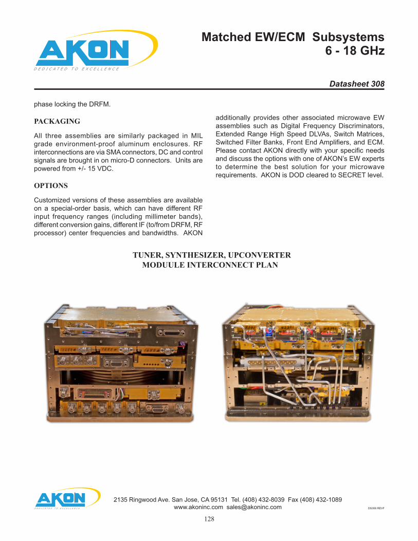
PACKAGING
All three assemblies are similarly packaged in MIL grade environment-proof aluminum enclosures. RF interconnections are via SMA connectors, DC and control signals are brought in on micro-D connectors. Units are powered from +/- 15 VDC.
OPTIONS
Customized versions of these assemblies are available on a special-order basis, which can have different RF input frequency ranges (including millimeter bands), different conversion gains, different IF (to/from DRFM, RF processor) center frequencies and bandwidths. AKON
TUNER, SYNTHESIZER, UPCONVERTER MODUULE INTERCONNECT PLAN
Datasheet 308
Matched EW/ECM Subsystems6 - 18 GHz
DS308 REVF
2135 Ringwood Ave. San Jose, CA 95131 Tel. (408) 432-8039 Fax (408) 432-1089www.akoninc.com [email protected]
128

OUTLINE DRAWING:
Datasheet 308
Matched EW/ECM Subsystems6 - 18 GHz
0 .31
1.25
1.42
2.29
2.90
3.51
4.12
4.73 5.04
3.82
0
6X
.41
.98
2.3
6
3X
2.85
3.5
6
2.3
0
0
.99
1.0
5
3X
2.37
0
.84
.96
2.58 2.95
4.20 3.97
4.50
5.03
.96
3.8
6
.39
15X SMA FEMALEPER MIL-STD-348
21 PIN MICRO-D MALEINTERFACE PERMIL-STD-83513
2X 15 PIN MICRO-D MALE INTERFACE PER MIL-DTL-83513
31 PIN MICRO-D MALEINTERFACE PERMIL-STD-83513
MOUNTING SURFACE
10X .18 THRU4X .18 X 45°
0
.25
.24
6.1
5
5X
6.39
6.6
4
0
1.99
3.21
4.43
5.52
0
.06
1.41
2.76
4.11
5.47 5.72
.20
CONNECTOR DESIGNATIONCONNECTOR FUNCTION
J1 RF INJ2 RF BITEJ3 IF OUTJ4 IF INJ5 RF OUTJ6 LO1J7 LO2J8 LO3J9 NCJ10 NCJ11 FROM DTOJ12 ACT DET. 1J13 ACT DET. 2J14 ACT DET.3J17 POWER/CONTROL 1 LOJ18 POWER/ CONTROL UP CONVERTERJ19 POWER CONTROL 3 CH. ACT. DET.J21 EXT. 50 OHM TERM.J22 POWER CONTROL DOWN CONVERTER
J17-15 PIN MICRO-D INTERFACEPIN FUNCTION1 +15 V2 +15 V RTN/GND3 +15V4 +15 V RTN/GND5 -15 V6 -15V RTN/GND7 GND8 B09 B110 B211 B312 B413 B514 B615 SPARE
J22-15 PIN MICRO-D INTERFACEPIN FUNCNTION1 +15 V2 +15 V RTN/GND3 -15 V4 -15 V RTN/GND5 B76 B87 B98 B109 B11
10 B1211 B1312 GND13 B4614 B4715 B48
J19-21 PIN MICRO-D INTERFACEPIN FUNCTION1 +15 V2 +15 V RTN/GND3 +15 V4 +15 V RTN/GND5 -15 V6 -15 V RTN/GND7 B268 B279 B2810 B2911 B3012 B3113 GND14 B3215 B3316 B3417 B3518 B3619 B3720 GND21 SPARE
J18- 31 PIN MICRO-D INTERFACEPIN FUNCTION1 +15 V2 +15V RTN/GND3 +15 V4 +15 V RTN/GND5 -15 V6 -15 V RTN/GND7 SPARE8 SPARE9 SPARE10 SPARE11 SPARE12 SPARE13 SPARE14 SPARE15 SPARE16 SPARE17 SPARE18 B1419 B1520 B1621 B1722 B1823 B1924 GND25 B2026 B2127 B2228 B2329 B2430 B2531 GND
DS308 REVF
2135 Ringwood Ave. San Jose, CA 95131 Tel. (408) 432-8039 Fax (408) 432-1089www.akoninc.com [email protected]
129


![ANT-GFPCB-1 - Farnell · 2019. 2. 12. · 2. 3700000 GHZ 2.1716 > . 5700000 . GHZ 1. 121 Log Mag 10.00d8/ Ref 0.000dB [F-2] Z. 3200000 GHZ S. db 3700000 GHZ 28. dB 00000 GHZ . 205](https://img.pdfslide.tips/doc/110x75/60ce6348252a1d5fef6ae592/ant-gfpcb-1-2019-2-12-2-3700000-ghz-21716-5700000-ghz-1-121-log.jpg)