Embed Size (px)
Citation preview
Issue 1
Document xxx-xxxxx – Rev A – MO/YR
MAX Graphic Platform™
User Manual

Revisions
Issue Date Description
1.0 March 12, 2010

M A X G R A P H I C P L A T F O R M ™ U S E R M A N U A L
Table of Contents
i
About this Guide . . . . . . . . . . . . . . . . . . . . . . . . . . . . . . . . . . . . . . . . . . . . . . . . . . . . . . . . . . . . .1
Scope . . . . . . . . . . . . . . . . . . . . . . . . . . . . . . . . . . . . . . . . . . . . . . . . . . . . . . . . . . . . . . . . . . . . . . . . . . . . . . . . . . . . 1
Intended Audience . . . . . . . . . . . . . . . . . . . . . . . . . . . . . . . . . . . . . . . . . . . . . . . . . . . . . . . . . . . . . . . . . . . . . . . . . 1
Document Structure . . . . . . . . . . . . . . . . . . . . . . . . . . . . . . . . . . . . . . . . . . . . . . . . . . . . . . . . . . . . . . . . . . . . . . . . 1
Introduction to Max Graphic Platform (MGP) . . . . . . . . . . . . . . . . . . . . . . . . . . . . . . . . . . . . .3
Overview . . . . . . . . . . . . . . . . . . . . . . . . . . . . . . . . . . . . . . . . . . . . . . . . . . . . . . . . . . . . . . . . . . . . . . . . . . . . . . . . . 3
Hardware and Software Requirements . . . . . . . . . . . . . . . . . . . . . . . . . . . . . . . . . . . . . . . . . . . . . . . . . . . . . . . . . 3
Design Concepts . . . . . . . . . . . . . . . . . . . . . . . . . . . . . . . . . . . . . . . . . . . . . . . . . . . . . . . . . . . . .5
Graphical Interface . . . . . . . . . . . . . . . . . . . . . . . . . . . . . . . . . . . . . . . . . . . . . . . . . . . . . . . . . . . . . . . . . . . . . . . . . 5
Events Overview . . . . . . . . . . . . . . . . . . . . . . . . . . . . . . . . . . . . . . . . . . . . . . . . . . . . . . . . . . . . . . . . . . . . . . . . . . . 6
MGP Operator Events . . . . . . . . . . . . . . . . . . . . . . . . . . . . . . . . . . . . . . . . . . . . . . . . . . . . . . . . . . . . . . . . . . . . . . . 6
MAXPRO™ VMS Events . . . . . . . . . . . . . . . . . . . . . . . . . . . . . . . . . . . . . . . . . . . . . . . . . . . . . . . . . . . . . . . . . . . . . . 7
Users . . . . . . . . . . . . . . . . . . . . . . . . . . . . . . . . . . . . . . . . . . . . . . . . . . . . . . . . . . . . . . . . . . . . . . . . . . . . . . . . . . . . . 7
Installation . . . . . . . . . . . . . . . . . . . . . . . . . . . . . . . . . . . . . . . . . . . . . . . . . . . . . . . . . . . . . . . . . .9
Overview . . . . . . . . . . . . . . . . . . . . . . . . . . . . . . . . . . . . . . . . . . . . . . . . . . . . . . . . . . . . . . . . . . . . . . . . . . . . . . . . . 9
Video Interface Card Installation . . . . . . . . . . . . . . . . . . . . . . . . . . . . . . . . . . . . . . . . . . . . . . . . . . . . . . . . . . . . . . 9
Touch Screen Interface . . . . . . . . . . . . . . . . . . . . . . . . . . . . . . . . . . . . . . . . . . . . . . . . . . . . . . . . . . . . . . . . . . . . . . 9
MGP Installation . . . . . . . . . . . . . . . . . . . . . . . . . . . . . . . . . . . . . . . . . . . . . . . . . . . . . . . . . . . . . . . . . . . . . . . . . . 10
MGP Graphical Components . . . . . . . . . . . . . . . . . . . . . . . . . . . . . . . . . . . . . . . . . . . . . . . . . .11
Overview . . . . . . . . . . . . . . . . . . . . . . . . . . . . . . . . . . . . . . . . . . . . . . . . . . . . . . . . . . . . . . . . . . . . . . . . . . . . . . . . 11
File Menu . . . . . . . . . . . . . . . . . . . . . . . . . . . . . . . . . . . . . . . . . . . . . . . . . . . . . . . . . . . . . . . . . . . . . . . . . . . . . . . . 11
Window Menu . . . . . . . . . . . . . . . . . . . . . . . . . . . . . . . . . . . . . . . . . . . . . . . . . . . . . . . . . . . . . . . . . . . . . . . . . . . . 12
Settings Menu . . . . . . . . . . . . . . . . . . . . . . . . . . . . . . . . . . . . . . . . . . . . . . . . . . . . . . . . . . . . . . . . . . . . . . . . . . . . 13
MGP Defaults . . . . . . . . . . . . . . . . . . . . . . . . . . . . . . . . . . . . . . . . . . . . . . . . . . . . . . . . . . . . . . . . . . . . . . . . . . 14
Manage Bitmaps . . . . . . . . . . . . . . . . . . . . . . . . . . . . . . . . . . . . . . . . . . . . . . . . . . . . . . . . . . . . . . . . . . . . . . . 17
Edit Overlays . . . . . . . . . . . . . . . . . . . . . . . . . . . . . . . . . . . . . . . . . . . . . . . . . . . . . . . . . . . . . . . . . . . . . . . . . . 18
Manage Users . . . . . . . . . . . . . . . . . . . . . . . . . . . . . . . . . . . . . . . . . . . . . . . . . . . . . . . . . . . . . . . . . . . . . . . . . 27
Picture Settings . . . . . . . . . . . . . . . . . . . . . . . . . . . . . . . . . . . . . . . . . . . . . . . . . . . . . . . . . . . . . . . . . . . . . . . . 29
Hot Spot Menu . . . . . . . . . . . . . . . . . . . . . . . . . . . . . . . . . . . . . . . . . . . . . . . . . . . . . . . . . . . . . . . . . . . . . . . . . . . 29
Help menu . . . . . . . . . . . . . . . . . . . . . . . . . . . . . . . . . . . . . . . . . . . . . . . . . . . . . . . . . . . . . . . . . . . . . . . . . . . . . . . 30
Commissioning . . . . . . . . . . . . . . . . . . . . . . . . . . . . . . . . . . . . . . . . . . . . . . . . . . . . . . . . . . . . .33
Overview . . . . . . . . . . . . . . . . . . . . . . . . . . . . . . . . . . . . . . . . . . . . . . . . . . . . . . . . . . . . . . . . . . . . . . . . . . . . . . . . 33
Standard Installation . . . . . . . . . . . . . . . . . . . . . . . . . . . . . . . . . . . . . . . . . . . . . . . . . . . . . . . . . . . . . . . . . . . . . . . 33
Users . . . . . . . . . . . . . . . . . . . . . . . . . . . . . . . . . . . . . . . . . . . . . . . . . . . . . . . . . . . . . . . . . . . . . . . . . . . . . . . . . 33
Overlays . . . . . . . . . . . . . . . . . . . . . . . . . . . . . . . . . . . . . . . . . . . . . . . . . . . . . . . . . . . . . . . . . . . . . . . . . . . . . . 34
MGP Defaults . . . . . . . . . . . . . . . . . . . . . . . . . . . . . . . . . . . . . . . . . . . . . . . . . . . . . . . . . . . . . . . . . . . . . . . . . . 37
Basic Setup Guide . . . . . . . . . . . . . . . . . . . . . . . . . . . . . . . . . . . . . . . . . . . . . . . . . . . . . . . . . . . . . . . . . . . . . . . . . 38
Configuring the MAXPRO™ VMS . . . . . . . . . . . . . . . . . . . . . . . . . . . . . . . . . . . . . . . . . . . . . . . . . . . . . . . . . . 38
Configuring the MGP . . . . . . . . . . . . . . . . . . . . . . . . . . . . . . . . . . . . . . . . . . . . . . . . . . . . . . . . . . . . . . . . . . . . 39
Communicating between the MAXPRO™ VMS and the MGP . . . . . . . . . . . . . . . . . . . . . . . . . . . . . . . . . . . 39
Displaying Video on the MGP . . . . . . . . . . . . . . . . . . . . . . . . . . . . . . . . . . . . . . . . . . . . . . . . . . . . . . . . . . . . . 40
Advanced Setup Guide . . . . . . . . . . . . . . . . . . . . . . . . . . . . . . . . . . . . . . . . . . . . . . . . . . . . . . . . . . . . . . . . . . . . . 41

M A X G R A P H I C P L A T F O R M ™ U S E R M A N U A L
Table of Contents
ii
Creating an Overlay. . . . . . . . . . . . . . . . . . . . . . . . . . . . . . . . . . . . . . . . . . . . . . . . . . . . . . . . . . . . . . . . . . . . . . 41
Adding Hotspots to an Overlay . . . . . . . . . . . . . . . . . . . . . . . . . . . . . . . . . . . . . . . . . . . . . . . . . . . . . . . . . . . . 43
Editing Hotspot Graphics . . . . . . . . . . . . . . . . . . . . . . . . . . . . . . . . . . . . . . . . . . . . . . . . . . . . . . . . . . . . . . . . . 43
Generating Events from a Hotspot Press. . . . . . . . . . . . . . . . . . . . . . . . . . . . . . . . . . . . . . . . . . . . . . . . . . . . . 50
Responding to Events . . . . . . . . . . . . . . . . . . . . . . . . . . . . . . . . . . . . . . . . . . . . . . . . . . . . . . . . . . . . . . . . . . . . 55
Troubleshooting . . . . . . . . . . . . . . . . . . . . . . . . . . . . . . . . . . . . . . . . . . . . . . . . . . . . . . . . . . . . . . . . . . . . . . . . . . 56
Colors in an Overlay Become Corrupted . . . . . . . . . . . . . . . . . . . . . . . . . . . . . . . . . . . . . . . . . . . . . . . . . . . . . 56
Bitmaps do not Import Correctly . . . . . . . . . . . . . . . . . . . . . . . . . . . . . . . . . . . . . . . . . . . . . . . . . . . . . . . . . . . 57
Index . . . . . . . . . . . . . . . . . . . . . . . . . . . . . . . . . . . . . . . . . . . . . . . . . . . . . . . . . . . . . . . . . . . . .59
. .
. .
.
A B O U T T H I S G U I D E
Scope
Max Graphic Platform™ User Manual 1
1. . . . .
. . . . . . . . . . . . . . . . . . . . . . . . . . . . . . . . . . .ABOUT THIS GUIDE
. . . . . . . . . . . . . . . . . . . . . . . . . . . . . . . . . . . . . . . . . . . . . . . . . . . . . . . . . . .SCOPE
This guide helps you in setting up the MGP and then discuss each menu items and dialogboxes provided in the setup menu. The guide also discusses the environment that is set up inthe software to meet the individual needs of all CCTV systems.
. . . . . . . . . . . . . . . . . . . . . . . . . . . . . . . . . . . . . . . . . . . . . . . . . . . . . . . . . . .INTENDED AUDIENCE
This guide is intended for the field and commissioning engineers of MAXPRO™ VMS R200.
. . . . . . . . . . . . . . . . . . . . . . . . . . . . . . . . . . . . . . . . . . . . . . . . . . . . . . . . . . .DOCUMENT STRUCTURE
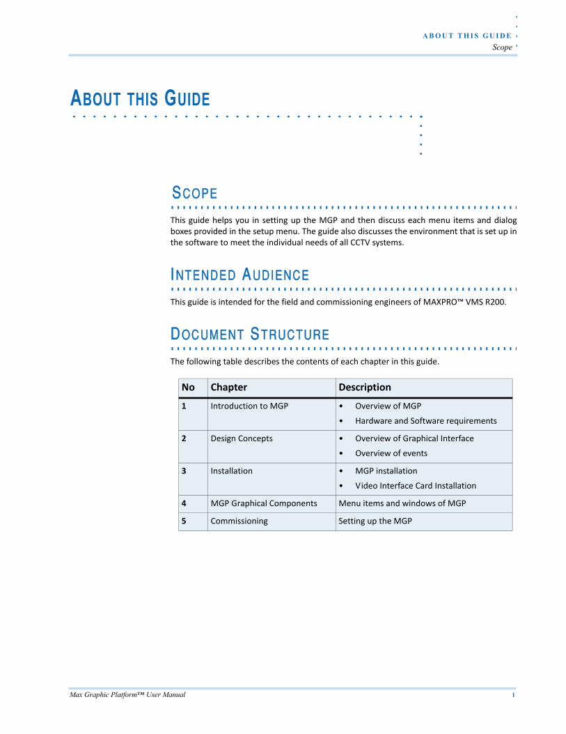
The following table describes the contents of each chapter in this guide.
No Chapter Description
1 Introduction to MGP • Overview of MGP
• Hardware and Software requirements
2 Design Concepts • Overview of Graphical Interface
• Overview of events
3 Installation • MGP installation
• Video Interface Card Installation
4 MGP Graphical Components Menu items and windows of MGP
5 Commissioning Setting up the MGP

Max Graphic Platform™ User Manual 3
1INTRODUCTION TO MAX GRAPHIC PLATFORM
. . . . .. . . . . . . . . . . . . . . . . . . . . . . . . . . . . . . . . . .(MGP)
. . . . . . . . . . . . . . . . . . . . . . . . . . . . . . . . . . . . . . . . . . . . . . . . . . . . . . . . . . .OVERVIEW
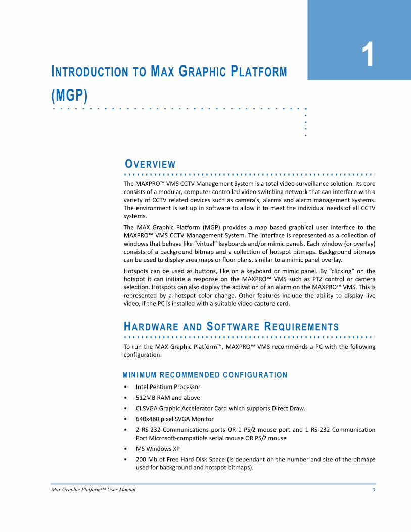
The MAXPRO™ VMS CCTV Management System is a total video surveillance solution. Its coreconsists of a modular, computer controlled video switching network that can interface with avariety of CCTV related devices such as camera's, alarms and alarm management systems.The environment is set up in software to allow it to meet the individual needs of all CCTVsystems.
The MAX Graphic Platform (MGP) provides a map based graphical user interface to theMAXPRO™ VMS CCTV Management System. The interface is represented as a collection ofwindows that behave like “virtual” keyboards and/or mimic panels. Each window (or overlay)consists of a background bitmap and a collection of hotspot bitmaps. Background bitmapscan be used to display area maps or floor plans, similar to a mimic panel overlay.
Hotspots can be used as buttons, like on a keyboard or mimic panel. By “clicking” on thehotspot it can initiate a response on the MAXPRO™ VMS such as PTZ control or cameraselection. Hotspots can also display the activation of an alarm on the MAXPRO™ VMS. This isrepresented by a hotspot color change. Other features include the ability to display livevideo, if the PC is installed with a suitable video capture card.
. . . . . . . . . . . . . . . . . . . . . . . . . . . . . . . . . . . . . . . . . . . . . . . . . . . . . . . . . . .HARDWARE AND SOFTWARE REQUIREMENTS
To run the MAX Graphic Platform™, MAXPRO™ VMS recommends a PC with the followingconfiguration.
MINIMUM RECOMMENDED CONFIGURATION• Intel Pentium Processor
• 512MB RAM and above
• CI SVGA Graphic Accelerator Card which supports Direct Draw.
• 640x480 pixel SVGA Monitor
• 2 RS‐232 Communications ports OR 1 PS/2 mouse port and 1 RS‐232 CommunicationPort Microsoft‐compatible serial mouse OR PS/2 mouse
• MS Windows XP
• 200 Mb of Free Hard Disk Space (Is dependant on the number and size of the bitmapsused for background and hotspot bitmaps).
I N T R O D U C T I O N T O M A X G R A P H I C P L A T F O R M ( M G P )
Hardware and Software Requirements
4 Max Graphic Platform™ User Manual
1
OPTIONS• Hauppauge WinTV card for live video window display.
• MicroTouch Touch Screen Interface and additional RS‐232 Communications port fortouch screen support.
Max Graphic Platform™ User Manual 5
2. . . . .
. . . . . . . . . . . . . . . . . . . . . . . . . . . . . . . . . . .DESIGN CONCEPTS
. . . . . . . . . . . . . . . . . . . . . . . . . . . . . . . . . . . . . . . . . . . . . . . . . . . . . . . . . . .GRAPHICAL INTERFACE
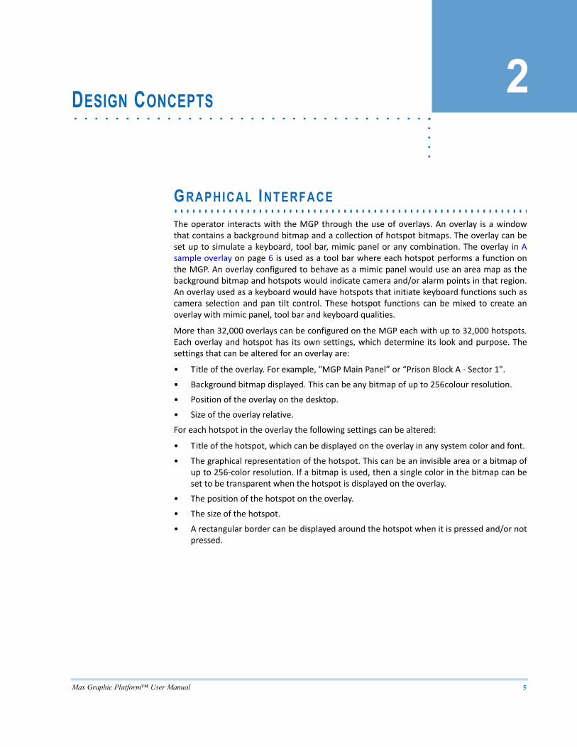
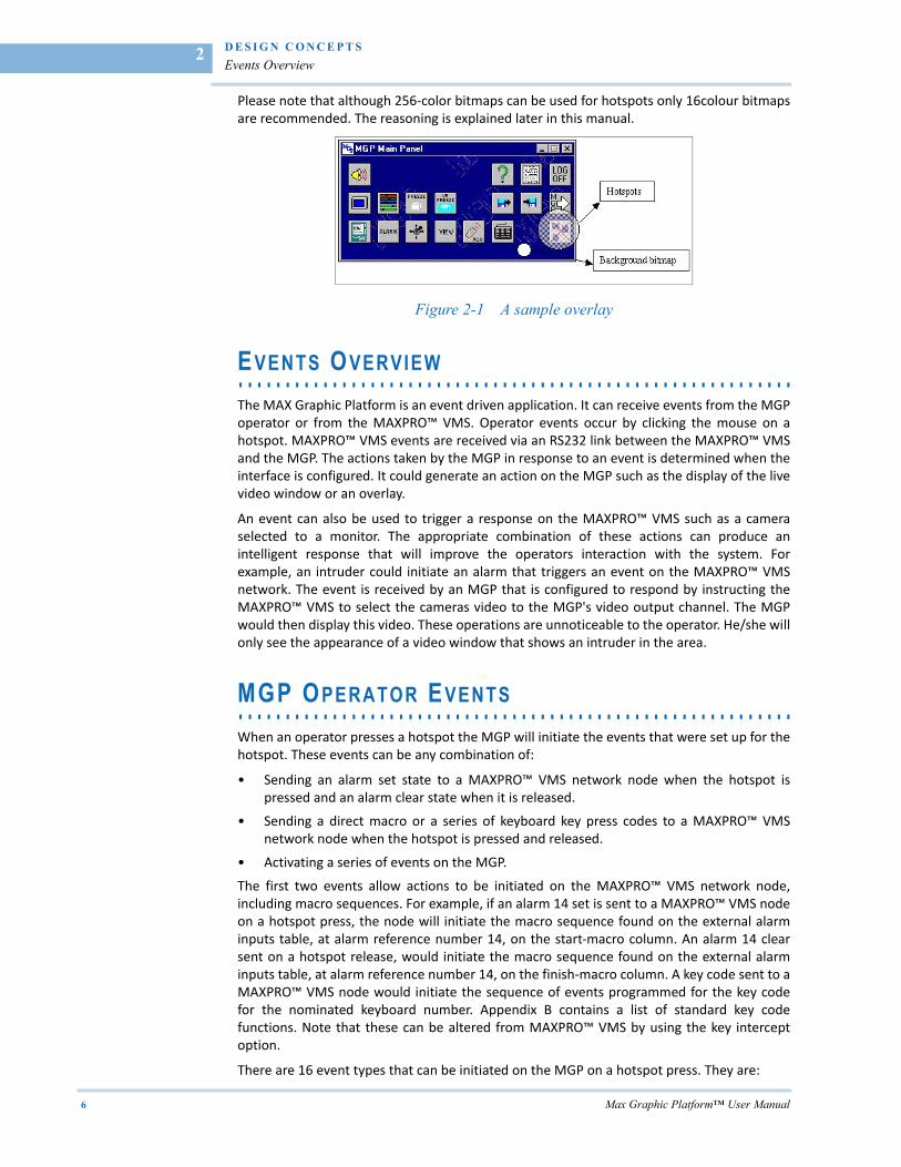
The operator interacts with the MGP through the use of overlays. An overlay is a windowthat contains a background bitmap and a collection of hotspot bitmaps. The overlay can beset up to simulate a keyboard, tool bar, mimic panel or any combination. The overlay in Asample overlay on page 6 is used as a tool bar where each hotspot performs a function onthe MGP. An overlay configured to behave as a mimic panel would use an area map as thebackground bitmap and hotspots would indicate camera and/or alarm points in that region.An overlay used as a keyboard would have hotspots that initiate keyboard functions such ascamera selection and pan tilt control. These hotspot functions can be mixed to create anoverlay with mimic panel, tool bar and keyboard qualities.
More than 32,000 overlays can be configured on the MGP each with up to 32,000 hotspots.Each overlay and hotspot has its own settings, which determine its look and purpose. Thesettings that can be altered for an overlay are:
• Title of the overlay. For example, "MGP Main Panel” or “Prison Block A ‐ Sector 1".
• Background bitmap displayed. This can be any bitmap of up to 256colour resolution.
• Position of the overlay on the desktop.
• Size of the overlay relative.
For each hotspot in the overlay the following settings can be altered:
• Title of the hotspot, which can be displayed on the overlay in any system color and font.
• The graphical representation of the hotspot. This can be an invisible area or a bitmap ofup to 256‐color resolution. If a bitmap is used, then a single color in the bitmap can beset to be transparent when the hotspot is displayed on the overlay.
• The position of the hotspot on the overlay.
• The size of the hotspot.
• A rectangular border can be displayed around the hotspot when it is pressed and/or notpressed.
D E S I G N C O N C E P T S
Events Overview
6 Max Graphic Platform™ User Manual
2
Please note that although 256‐color bitmaps can be used for hotspots only 16colour bitmapsare recommended. The reasoning is explained later in this manual.
Figure 2-1 A sample overlay
. . . . . . . . . . . . . . . . . . . . . . . . . . . . . . . . . . . . . . . . . . . . . . . . . . . . . . . . . . .EVENTS OVERVIEW
The MAX Graphic Platform is an event driven application. It can receive events from the MGPoperator or from the MAXPRO™ VMS. Operator events occur by clicking the mouse on ahotspot. MAXPRO™ VMS events are received via an RS232 link between the MAXPRO™ VMSand the MGP. The actions taken by the MGP in response to an event is determined when theinterface is configured. It could generate an action on the MGP such as the display of the livevideo window or an overlay.
An event can also be used to trigger a response on the MAXPRO™ VMS such as a cameraselected to a monitor. The appropriate combination of these actions can produce anintelligent response that will improve the operators interaction with the system. Forexample, an intruder could initiate an alarm that triggers an event on the MAXPRO™ VMSnetwork. The event is received by an MGP that is configured to respond by instructing theMAXPRO™ VMS to select the cameras video to the MGP's video output channel. The MGPwould then display this video. These operations are unnoticeable to the operator. He/she willonly see the appearance of a video window that shows an intruder in the area.
. . . . . . . . . . . . . . . . . . . . . . . . . . . . . . . . . . . . . . . . . . . . . . . . . . . . . . . . . . .MGP OPERATOR EVENTS
When an operator presses a hotspot the MGP will initiate the events that were set up for thehotspot. These events can be any combination of:
• Sending an alarm set state to a MAXPRO™ VMS network node when the hotspot ispressed and an alarm clear state when it is released.
• Sending a direct macro or a series of keyboard key press codes to a MAXPRO™ VMSnetwork node when the hotspot is pressed and released.
• Activating a series of events on the MGP.
The first two events allow actions to be initiated on the MAXPRO™ VMS network node,including macro sequences. For example, if an alarm 14 set is sent to a MAXPRO™ VMS nodeon a hotspot press, the node will initiate the macro sequence found on the external alarminputs table, at alarm reference number 14, on the start‐macro column. An alarm 14 clearsent on a hotspot release, would initiate the macro sequence found on the external alarminputs table, at alarm reference number 14, on the finish‐macro column. A key code sent to aMAXPRO™ VMS node would initiate the sequence of events programmed for the key codefor the nominated keyboard number. Appendix B contains a list of standard key codefunctions. Note that these can be altered from MAXPRO™ VMS by using the key interceptoption.
There are 16 event types that can be initiated on the MGP on a hotspot press. They are:
. .
. .
.
D E S I G N C O N C E P T S
MAXPRO™ VMS Events
Max Graphic Platform™ User Manual 7
• Display/Hide the overlay list. This window contains a list of all the MGP overlays and hasbuttons to display and hide overlays.
• Display/Hide the Active Alarms List. This window contains a list of all the MAX‐1000alarms that are active and are used on the MGP.
• Log off the MGP operator.
• Close all MGP windows that are displayed.
• Display the picture controls window.
• Enable/Disable MGP sound effects.
• Display MGP about dialog box.
• Display MGP license agreement.
• Display/Hide an overlay.
• Display/Hide the live video window.
• Freeze/Unfreeze the live video window.
• Save the video window image to a file and prompt for the file name.
• Save the video window image to a file without a prompt for the file name.
• Export the video window image to a file.
• Activate/Clear an internal MGP alarm.
• Activate/Clear an internal auxiliary control output.
Note: A complete information of these events is given later in this manual.
. . . . . . . . . . . . . . . . . . . . . . . . . . . . . . . . . . . . . . . . . . . . . . . . . . . . . . . . . . .MAXPRO™ VMS EVENTS
Every hotspot is capable of responding to 8 alarm or auxiliary control output states thatoccur on the MAXPRO™ VMS network. If the MGP receives a state change for any of theseevents then the appropriate actions are initiated. The actions can be any combination of:
• A change of one of the colors in the hotspot if the event is active and a return to thenormal color if the event is deactivated.
• The event appearing on the Alarm List if the event is active and removed if the event isdeactivated.
• Activating a series of MGP events.
For the first case the option is available to cycle colors for every active event. For example, ifa hotspot is set up to respond to two events, one with a color change of blue the other withgreen, then if both become active the hotspot will alternate between green and blue colorchanges. If only one event is active then the hotspot will toggle between the event color andthe normal color (i.e. the hotspot will appear to flash). The time between color changes is“hard‐wired” into the MGP at 0.5 seconds. If the cycle colors feature is not used then onlythe most recent event's color change is displayed.
. . . . . . . . . . . . . . . . . . . . . . . . . . . . . . . . . . . . . . . . . . . . . . . . . . . . . . . . . . .USERS
The MGP has two modes of operation: the set up mode and the operator mode. The set upmode allows the MGP configuration to be altered and operated, whereas the operator modeonly allows the MGP to be operated. To control access to both modes the MGP has two types
D E S I G N C O N C E P T S
Users
8 Max Graphic Platform™ User Manual
2
of users. The supervisor user has access to the set up mode of operation, whereas theoperator user has access to the operator mode.
Up to eight users can be created on the MGP. Each user is defined by its access mode, username and password. Every user on the MGP must have a unique user name and at least oneuser must have supervisor access.
Max Graphic Platform™ User Manual 9
3. . . . .
. . . . . . . . . . . . . . . . . . . . . . . . . . . . . . . . . . .INSTALLATION
. . . . . . . . . . . . . . . . . . . . . . . . . . . . . . . . . . . . . . . . . . . . . . . . . . . . . . . . . . .OVERVIEW
Follow these steps to install MGP.
• Install all hardware. If you are using existing hardware please ensure the hardwaremeets the system requirements.
• Install the WinTV™ video capture card.
• Install the MicroTouch touch screen interface.
• Install the MAX Graphic Platform software.
. . . . . . . . . . . . . . . . . . . . . . . . . . . . . . . . . . . . . . . . . . . . . . . . . . . . . . . . . . .V IDEO INTERFACE CARD INSTALLATION
For instructions on the installation and set up of the WinTV card and software please refer tothe documentation provided with the card. More information is provided later in thismanual.
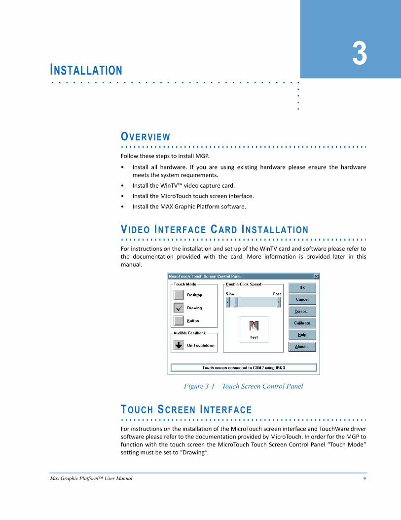
Figure 3-1 Touch Screen Control Panel
. . . . . . . . . . . . . . . . . . . . . . . . . . . . . . . . . . . . . . . . . . . . . . . . . . . . . . . . . . .TOUCH SCREEN INTERFACE
For instructions on the installation of the MicroTouch screen interface and TouchWare driversoftware please refer to the documentation provided by MicroTouch. In order for the MGP tofunction with the touch screen the MicroTouch Touch Screen Control Panel “Touch Mode”setting must be set to “Drawing”.
I N S T A L L A T I O N
MGP Installation
10 Max Graphic Platform™ User Manual
3
Note that if both the mouse and touch screen is required three serial ports are required ortwo serial ports and a PS/2 port and mouse. Also note that the mouse must be installedbefore the touch screen, otherwise the mouse installation will overwrite the Touch Screendriver.
. . . . . . . . . . . . . . . . . . . . . . . . . . . . . . . . . . . . . . . . . . . . . . . . . . . . . . . . . . .MGP INSTALLATION
Before installing the MGP software ensure that all the hardware is operating correctly andWindows™ is set up as required for the operator preferences to screen resolution etc, andthat all hardware device drivers (pointing device, Video Interface Direct Draw driver) areinstalled. (Note these settings may be adjusted at any time).
To install the MAX Graphic Platform, follow the on screen installation instructions of the MGPsetup in MAXPRO™ VMS DVD Tools folder.
Max Graphic Platform™ User Manual 11
4. . . . .
. . . . . . . . . . . . . . . . . . . . . . . . . . . . . . . . . . .MGP GRAPHICAL COMPONENTS
. . . . . . . . . . . . . . . . . . . . . . . . . . . . . . . . . . . . . . . . . . . . . . . . . . . . . . . . . . .OVERVIEW
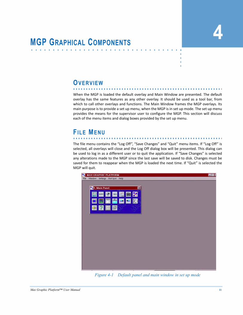
When the MGP is loaded the default overlay and Main Window are presented. The defaultoverlay has the same features as any other overlay. It should be used as a tool bar, fromwhich to call other overlays and functions. The Main Window frames the MGP overlays. Itsmain purpose is to provide a set up menu, when the MGP is in set up mode. The set up menuprovides the means for the supervisor user to configure the MGP. This section will discusseach of the menu items and dialog boxes provided by the set up menu.
. . . . . . . . . . . . . . . . . . . . . . . . . . . . . . . . . . . . . . . . . . . . . . . . . . . . . . . . . . .F ILE MENU
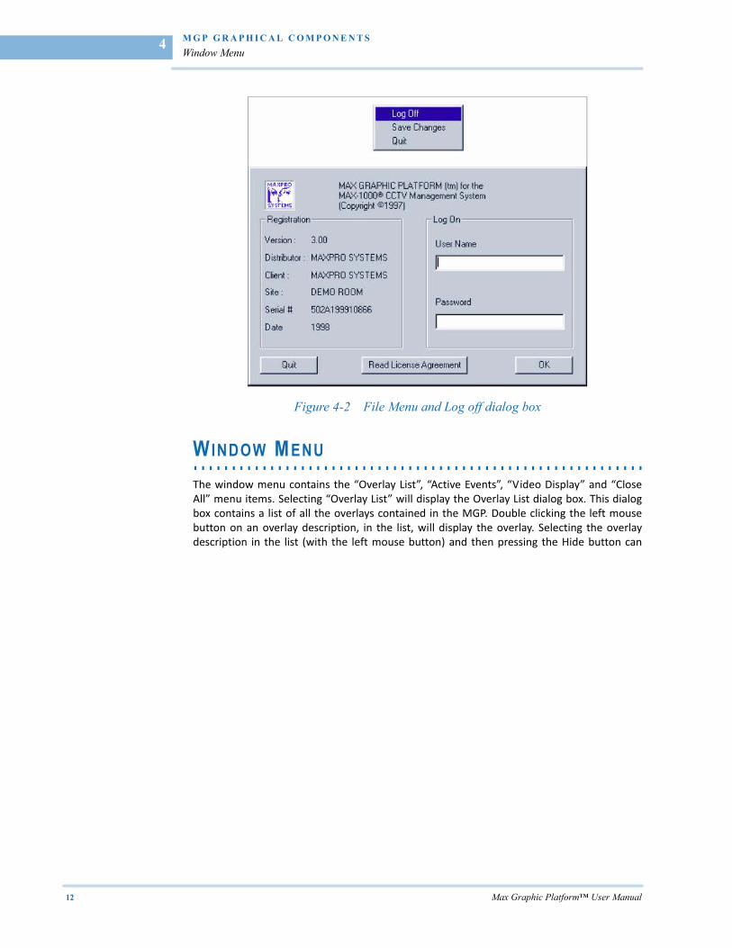
The file menu contains the “Log Off”, “Save Changes” and “Quit” menu items. If “Log Off” isselected, all overlays will close and the Log Off dialog box will be presented. This dialog canbe used to log in as a different user or to quit the application. If “Save Changes” is selectedany alterations made to the MGP since the last save will be saved to disk. Changes must besaved for them to reappear when the MGP is loaded the next time. If “Quit” is selected theMGP will quit.
Figure 4-1 Default panel and main window in set up mode
M G P G R A P H I C A L C O M P O N E N T S
Window Menu
12 Max Graphic Platform™ User Manual
4
Figure 4-2 File Menu and Log off dialog box
. . . . . . . . . . . . . . . . . . . . . . . . . . . . . . . . . . . . . . . . . . . . . . . . . . . . . . . . . . .WINDOW MENU
The window menu contains the “Overlay List”, “Active Events”, “Video Display” and “CloseAll” menu items. Selecting “Overlay List” will display the Overlay List dialog box. This dialogbox contains a list of all the overlays contained in the MGP. Double clicking the left mousebutton on an overlay description, in the list, will display the overlay. Selecting the overlaydescription in the list (with the left mouse button) and then pressing the Hide button can
. .
. .
.
M G P G R A P H I C A L C O M P O N E N T S
Settings Menu
Max Graphic Platform™ User Manual 13
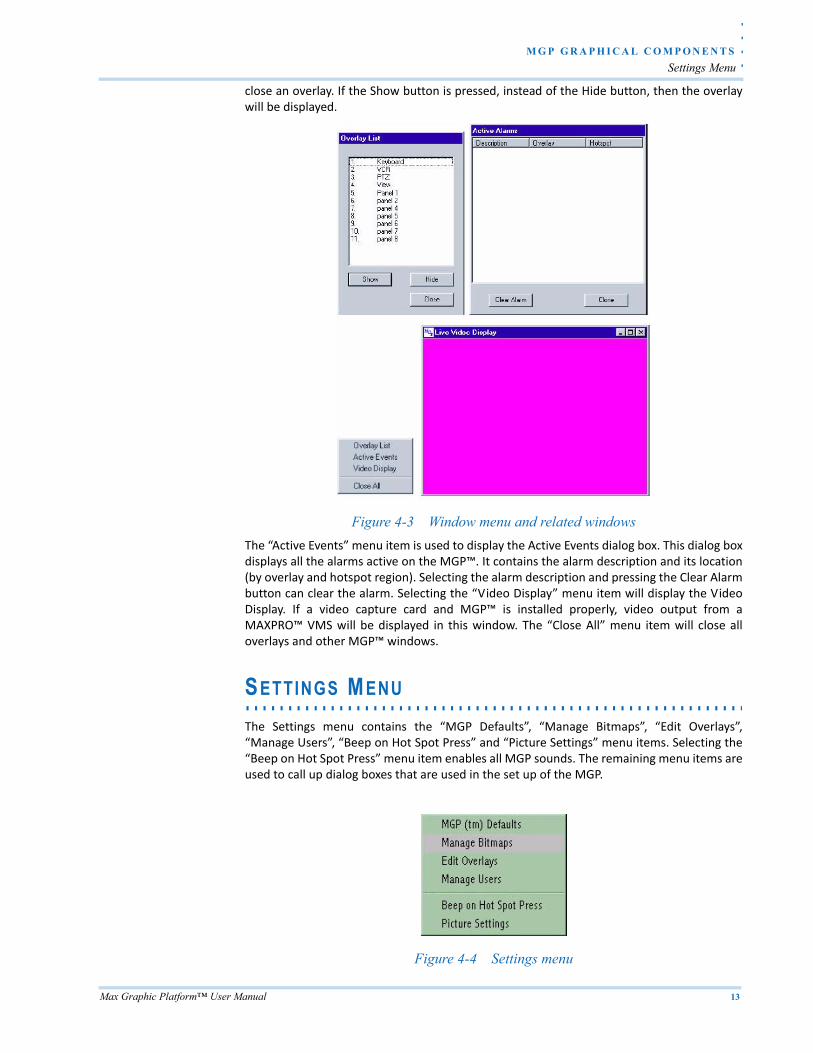
close an overlay. If the Show button is pressed, instead of the Hide button, then the overlaywill be displayed.
Figure 4-3 Window menu and related windows
The “Active Events” menu item is used to display the Active Events dialog box. This dialog boxdisplays all the alarms active on the MGP™. It contains the alarm description and its location(by overlay and hotspot region). Selecting the alarm description and pressing the Clear Alarmbutton can clear the alarm. Selecting the “Video Display” menu item will display the VideoDisplay. If a video capture card and MGP™ is installed properly, video output from aMAXPRO™ VMS will be displayed in this window. The “Close All” menu item will close alloverlays and other MGP™ windows.
. . . . . . . . . . . . . . . . . . . . . . . . . . . . . . . . . . . . . . . . . . . . . . . . . . . . . . . . . . .SETTINGS MENU
The Settings menu contains the “MGP Defaults”, “Manage Bitmaps”, “Edit Overlays”,“Manage Users”, “Beep on Hot Spot Press” and “Picture Settings” menu items. Selecting the“Beep on Hot Spot Press” menu item enables all MGP sounds. The remaining menu items areused to call up dialog boxes that are used in the set up of the MGP.
Figure 4-4 Settings menu
M G P G R A P H I C A L C O M P O N E N T S
Settings Menu
14 Max Graphic Platform™ User Manual
4
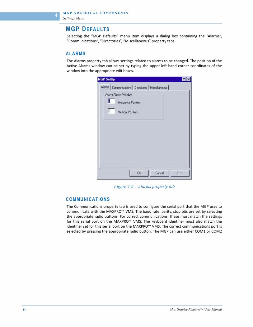
MGP D EFAULTS Selecting the “MGP Defaults” menu item displays a dialog box containing the “Alarms”,“Communications”, “Directories”, “Miscellaneous” property tabs.
ALARMSThe Alarms property tab allows settings related to alarms to be changed. The position of theActive Alarms window can be set by typing the upper left hand corner coordinates of thewindow into the appropriate edit boxes.
Figure 4-5 Alarms property tab
COMMUNICATIONS The Communications property tab is used to configure the serial port that the MGP uses tocommunicate with the MAXPRO™ VMS. The baud rate, parity, stop bits are set by selectingthe appropriate radio buttons. For correct communications, these must match the settingsfor this serial port on the MAXPRO™ VMS. The keyboard identifier must also match theidentifier set for this serial port on the MAXPRO™ VMS. The correct communications port isselected by pressing the appropriate radio button. The MGP can use either COM1 or COM2

. .
. .
.
M G P G R A P H I C A L C O M P O N E N T S
Settings Menu
Max Graphic Platform™ User Manual 15
serial ports. The MAXPRO™ VMS default node ID should be set to the node number of theMAXPRO™ VMS that is connected to the MGP.
Figure 4-6 Communications property tab
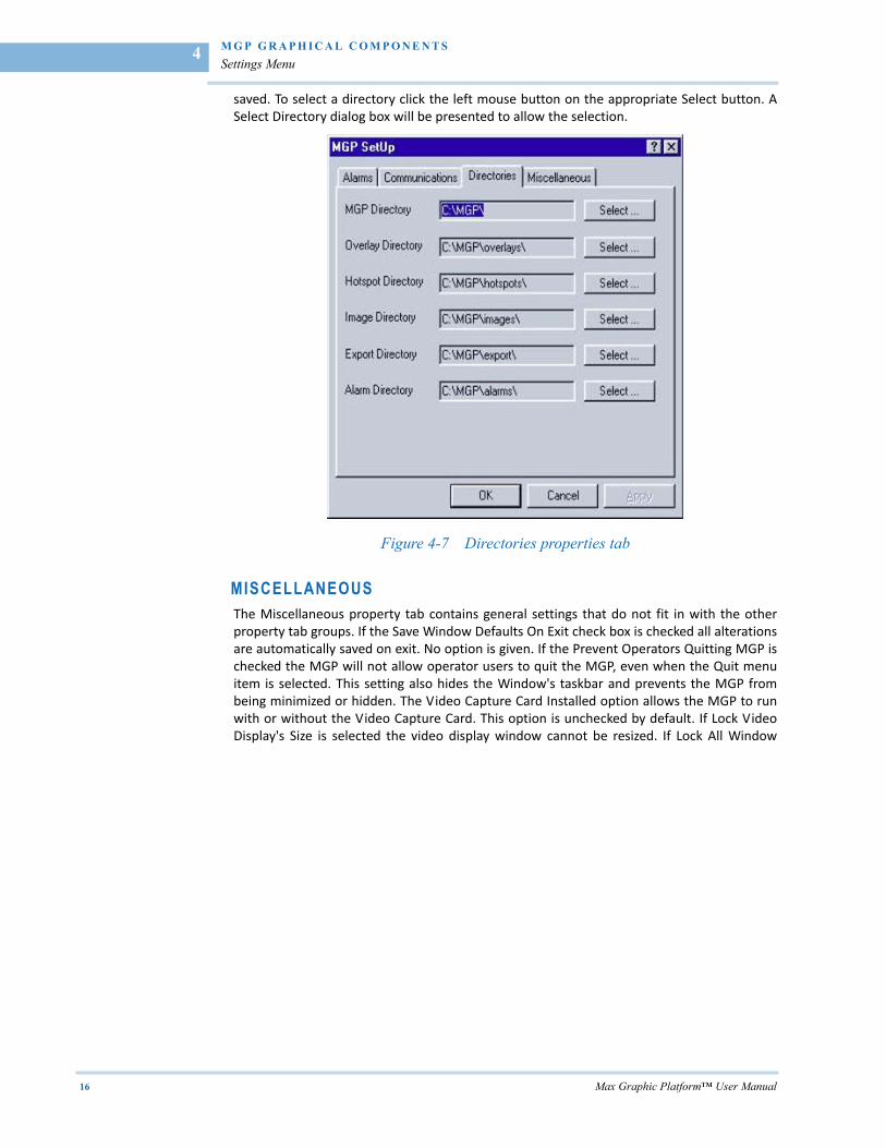
DIRECTORIES The Directories property tab is used to set up the MAGPIE's directory structure. MGPdirectories are used to group similar files. There are six types of MGP directories. The MGPdirectory is the directory where the MGP executable (MGP.exe) and its configuration files(*.MGP files) are stored. The Overlay directory is where the background overlay bitmaps arestored. The Hotspot directory is where the hotspot bitmaps are stored. The image directoryis the default directory where live video images are saved. The export directory is thedirectory where exported images are saved. (Exported images are ones that are to beexported to a database application). The alarm directory is where alarm video images are
M G P G R A P H I C A L C O M P O N E N T S
Settings Menu
16 Max Graphic Platform™ User Manual
4
saved. To select a directory click the left mouse button on the appropriate Select button. ASelect Directory dialog box will be presented to allow the selection.
Figure 4-7 Directories properties tab
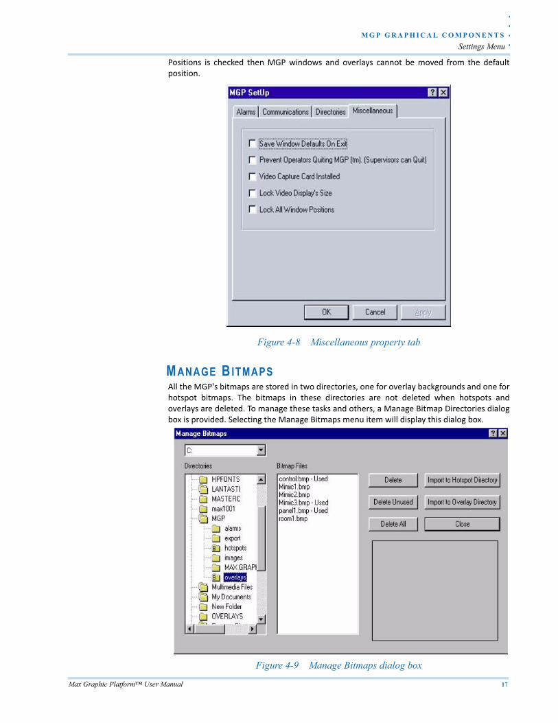
MISCELLANEOUSThe Miscellaneous property tab contains general settings that do not fit in with the otherproperty tab groups. If the Save Window Defaults On Exit check box is checked all alterationsare automatically saved on exit. No option is given. If the Prevent Operators Quitting MGP ischecked the MGP will not allow operator users to quit the MGP, even when the Quit menuitem is selected. This setting also hides the Window's taskbar and prevents the MGP frombeing minimized or hidden. The Video Capture Card Installed option allows the MGP to runwith or without the Video Capture Card. This option is unchecked by default. If Lock VideoDisplay's Size is selected the video display window cannot be resized. If Lock All Window
. .
. .
.
M G P G R A P H I C A L C O M P O N E N T S
Settings Menu
Max Graphic Platform™ User Manual 17
Positions is checked then MGP windows and overlays cannot be moved from the defaultposition.
Figure 4-8 Miscellaneous property tab
MANAGE B ITMAPSAll the MGP's bitmaps are stored in two directories, one for overlay backgrounds and one forhotspot bitmaps. The bitmaps in these directories are not deleted when hotspots andoverlays are deleted. To manage these tasks and others, a Manage Bitmap Directories dialogbox is provided. Selecting the Manage Bitmaps menu item will display this dialog box.
Figure 4-9 Manage Bitmaps dialog box
M G P G R A P H I C A L C O M P O N E N T S
Settings Menu
18 Max Graphic Platform™ User Manual
4
Drives can be selected using the drop down list in the top left‐hand corner of the dialog box.Directories in these drives can be navigated using the tree list under the drive list. A yellowfolder icon presents directories in the list. There are three types of folder icon. Icons thatdisplay a single folder have no subdirectories. Folder icons that have two folders imply thatthe directory has subdirectories. Double clicking on these icons will reveal the subdirectories.The third type is a folder icon with an emblazoned “B”. These directories are the MGP'sbitmap directories. If a folder icon is selected, any bitmaps contained in the directory will bedisplayed in the Bitmap Files list box. If a bitmap file is selected a thumbnail of this image willappear in the dialog box. The selected bitmap can also be imported to the overlay or hotspotdirectory, or deleted, by pressing the appropriate button. All the bitmaps, in a directory, canbe deleted if the Delete All button is pressed.
If the bitmaps in a bitmap directory are displayed, any bitmaps used for hotspots orbackgrounds will be marked with “Used”. Any unused bitmaps can be deleted by pressing theDelete Unused button.
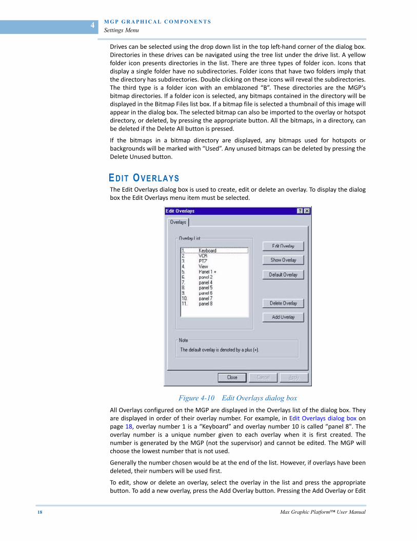
EDIT O VERLAYS The Edit Overlays dialog box is used to create, edit or delete an overlay. To display the dialogbox the Edit Overlays menu item must be selected.
Figure 4-10 Edit Overlays dialog box
All Overlays configured on the MGP are displayed in the Overlays list of the dialog box. Theyare displayed in order of their overlay number. For example, in Edit Overlays dialog box onpage 18, overlay number 1 is a “Keyboard” and overlay number 10 is called “panel 8". Theoverlay number is a unique number given to each overlay when it is first created. Thenumber is generated by the MGP (not the supervisor) and cannot be edited. The MGP willchoose the lowest number that is not used.
Generally the number chosen would be at the end of the list. However, if overlays have beendeleted, their numbers will be used first.
To edit, show or delete an overlay, select the overlay in the list and press the appropriatebutton. To add a new overlay, press the Add Overlay button. Pressing the Add Overlay or Edit
. .
. .
.
M G P G R A P H I C A L C O M P O N E N T S
Settings Menu
Max Graphic Platform™ User Manual 19
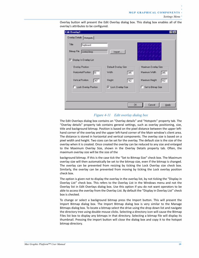
Overlay button will present the Edit Overlay dialog box. This dialog box enables all of theoverlay's attributes to be configured.
Figure 4-11 Edit overlay dialog box
The Edit Overlays dialog box contains an “Overlay details” and “Hotspots” property tab. The“Overlay details” property tab contains general settings, such as overlay positioning, size,title and background bitmap. Position is based on the pixel distance between the upper left‐hand corner of the overlay and the upper left‐hand corner of the Main window's client area.The distance is stored in horizontal and vertical components. The overlay size is based on apixel width and height. Two sizes can be set for the overlay. The default size is the size of theoverlay when it is created. Once created the overlay can be reduced to any size and enlargedto the Maximum Overlay Size, shown in the Overlay Details property tab. Often, themaximum overlay size will be the size of the
background bitmap. If this is the case tick the “Set to Bitmap Size” check box. The Maximumoverlay size will then automatically be set to the bitmap size, even if the bitmap is changed.The overlay can be prevented from resizing by ticking the Lock Overlay size check box.Similarly, the overlay can be prevented from moving by ticking the Lock overlay positioncheck box.
The option is given not to display the overlay in the overlay list, by not ticking the “Display inOverlay List” check box. This refers to the Overlay List in the Windows menu and not theOverlay list in Edit Overlays dialog box. Use this option if you do not want operators to beable to access the overlay from the Overlay List. By default the “Display in Overlay List” checkbox is checked.
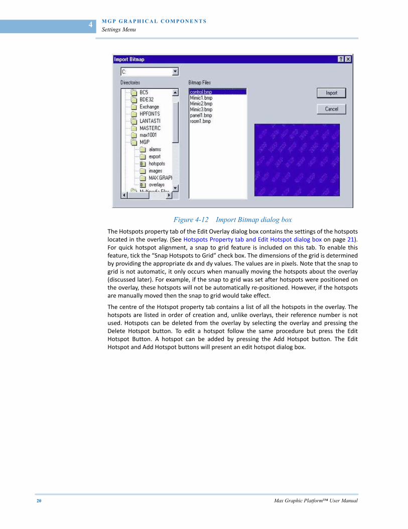
To change or select a background bitmap press the Import button. This will present theImport Bitmap dialog box. The Import Bitmap dialog box is very similar to the ManageBitmaps dialog box. To locate a bitmap select the drive using the drop down list and navigatethe directory tree using double mouse clicks. Selecting a directory icon will cause the BitmapFiles list box to display any bitmaps in that directory. Selecting a bitmap file will display itsthumbnail. Pressing the import button will close the dialog box and copy it to the hotspotbitmap directory.
M G P G R A P H I C A L C O M P O N E N T S
Settings Menu
20 Max Graphic Platform™ User Manual
4
Figure 4-12 Import Bitmap dialog box
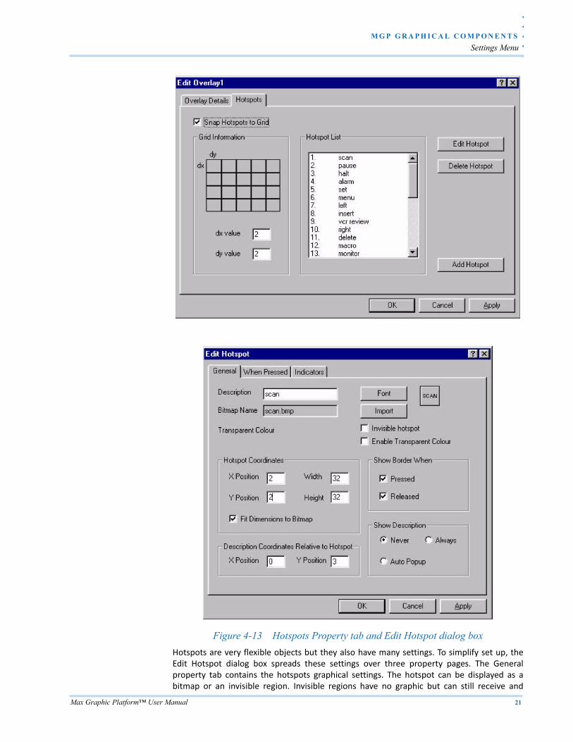
The Hotspots property tab of the Edit Overlay dialog box contains the settings of the hotspotslocated in the overlay. (See Hotspots Property tab and Edit Hotspot dialog box on page 21).For quick hotspot alignment, a snap to grid feature is included on this tab. To enable thisfeature, tick the “Snap Hotspots to Grid” check box. The dimensions of the grid is determinedby providing the appropriate dx and dy values. The values are in pixels. Note that the snap togrid is not automatic, it only occurs when manually moving the hotspots about the overlay(discussed later). For example, if the snap to grid was set after hotspots were positioned onthe overlay, these hotspots will not be automatically re‐positioned. However, if the hotspotsare manually moved then the snap to grid would take effect.
The centre of the Hotspot property tab contains a list of all the hotspots in the overlay. Thehotspots are listed in order of creation and, unlike overlays, their reference number is notused. Hotspots can be deleted from the overlay by selecting the overlay and pressing theDelete Hotspot button. To edit a hotspot follow the same procedure but press the EditHotspot Button. A hotspot can be added by pressing the Add Hotspot button. The EditHotspot and Add Hotspot buttons will present an edit hotspot dialog box.
. .
. .
.
M G P G R A P H I C A L C O M P O N E N T S
Settings Menu
Max Graphic Platform™ User Manual 21
Figure 4-13 Hotspots Property tab and Edit Hotspot dialog box
Hotspots are very flexible objects but they also have many settings. To simplify set up, theEdit Hotspot dialog box spreads these settings over three property pages. The Generalproperty tab contains the hotspots graphical settings. The hotspot can be displayed as abitmap or an invisible region. Invisible regions have no graphic but can still receive and
M G P G R A P H I C A L C O M P O N E N T S
Settings Menu
22 Max Graphic Platform™ User Manual
4
generate events. To make the hotspot invisible, tick the Invisible Hotspot check box. Toimport a bitmap for the hotspot press the Import button. This will display the import bitmapdialog box mentioned previously. If the hotspot is not invisible and no bitmap is imported,then a default Maxpro logo (32 by 32 pixels in size) is used. Hotspot bitmaps must beimported as a rectangular bitmap. However, hotspots can be displayed as irregular shapes byusing the transparent color feature. With this feature a single color in the bitmap can beselected as the transparent color. When displayed, the transparent color in the bitmap will beinvisible. Pressing the transparent region will not activate any events, because the region isno longer classed as a part of the hotspot. To enable transparent colors tick the “EnableTransparent Colors" check box. To select the transparent color, move the cursor over thetransparent color in the bitmap thumbnail and click the mouse button. The transparent colorwill be displayed in a rectangle below Bitmap Name edit box.
Hotspots can be given a raised and/or a pressed look (like a button) by ticking the “ShowBorder When” check boxes. If the Pressed check box is ticked then an indented border will bedisplayed when a hotspot is pressed. If the Released check box is ticked then a hotspot willhave a raised border when it is not pressed. Borders can be applied to invisible or bitmaphotspots.
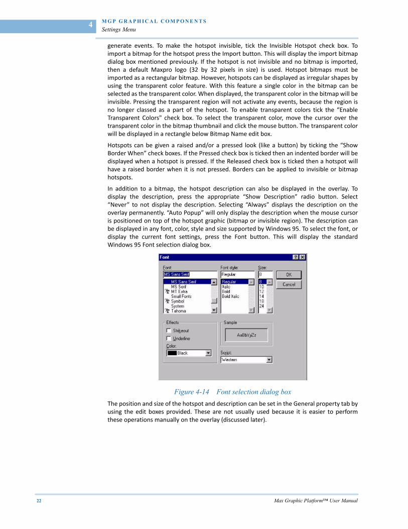
In addition to a bitmap, the hotspot description can also be displayed in the overlay. Todisplay the description, press the appropriate “Show Description” radio button. Select“Never” to not display the description. Selecting “Always” displays the description on theoverlay permanently. “Auto Popup” will only display the description when the mouse cursoris positioned on top of the hotspot graphic (bitmap or invisible region). The description canbe displayed in any font, color, style and size supported by Windows 95. To select the font, ordisplay the current font settings, press the Font button. This will display the standardWindows 95 Font selection dialog box.
Figure 4-14 Font selection dialog box
The position and size of the hotspot and description can be set in the General property tab byusing the edit boxes provided. These are not usually used because it is easier to performthese operations manually on the overlay (discussed later).
. .
. .
.
M G P G R A P H I C A L C O M P O N E N T S
Settings Menu
Max Graphic Platform™ User Manual 23
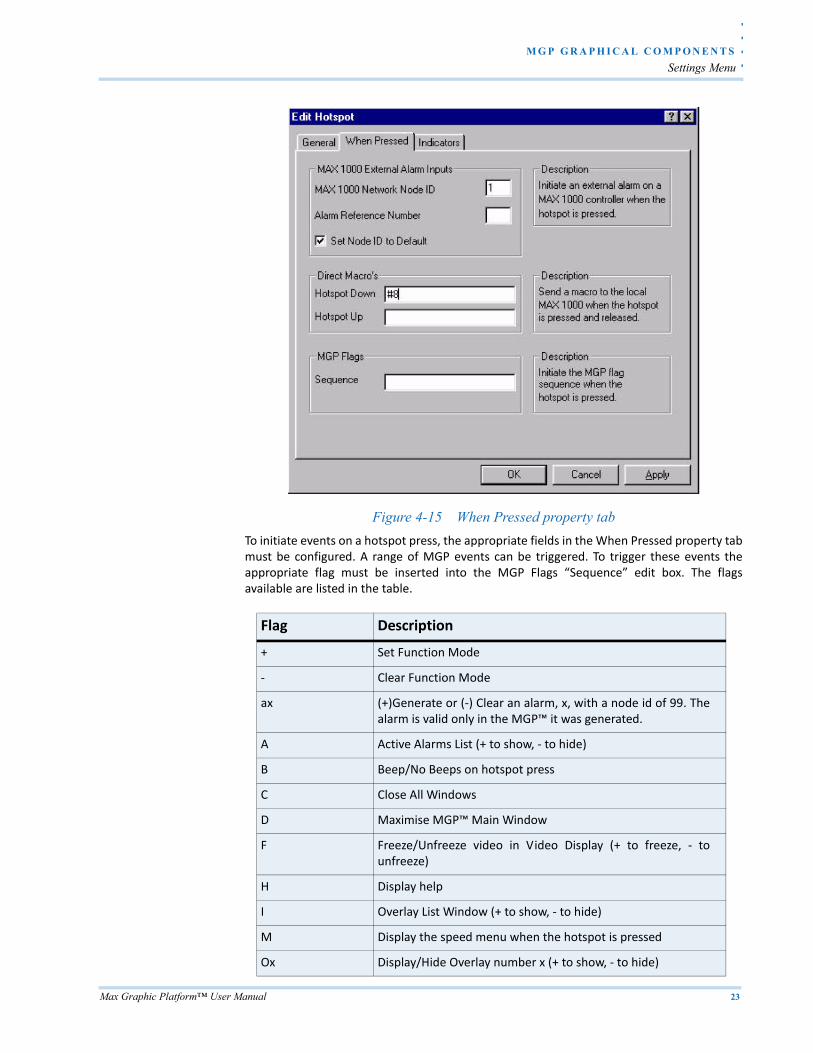
Figure 4-15 When Pressed property tab
To initiate events on a hotspot press, the appropriate fields in the When Pressed property tabmust be configured. A range of MGP events can be triggered. To trigger these events theappropriate flag must be inserted into the MGP Flags “Sequence” edit box. The flagsavailable are listed in the table.
Flag Description
+ Set Function Mode
‐ Clear Function Mode
ax (+)Generate or (‐) Clear an alarm, x, with a node id of 99. Thealarm is valid only in the MGP™ it was generated.
A Active Alarms List (+ to show, ‐ to hide)
B Beep/No Beeps on hotspot press
C Close All Windows
D Maximise MGP™ Main Window
F Freeze/Unfreeze video in Video Display (+ to freeze, ‐ tounfreeze)
H Display help
I Overlay List Window (+ to show, ‐ to hide)
M Display the speed menu when the hotspot is pressed
Ox Display/Hide Overlay number x (+ to show, ‐ to hide)
M G P G R A P H I C A L C O M P O N E N T S
Settings Menu
24 Max Graphic Platform™ User Manual
4
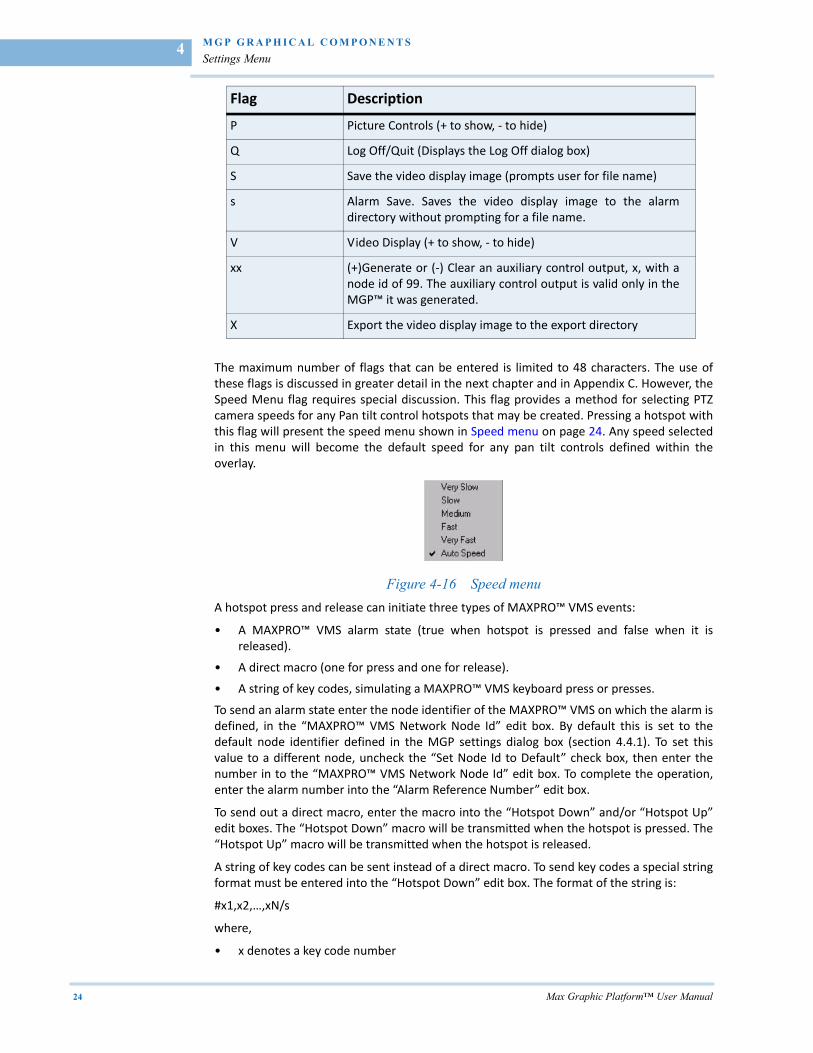
The maximum number of flags that can be entered is limited to 48 characters. The use ofthese flags is discussed in greater detail in the next chapter and in Appendix C. However, theSpeed Menu flag requires special discussion. This flag provides a method for selecting PTZcamera speeds for any Pan tilt control hotspots that may be created. Pressing a hotspot withthis flag will present the speed menu shown in Speed menu on page 24. Any speed selectedin this menu will become the default speed for any pan tilt controls defined within theoverlay.
Figure 4-16 Speed menu
A hotspot press and release can initiate three types of MAXPRO™ VMS events:
• A MAXPRO™ VMS alarm state (true when hotspot is pressed and false when it isreleased).
• A direct macro (one for press and one for release).
• A string of key codes, simulating a MAXPRO™ VMS keyboard press or presses.
To send an alarm state enter the node identifier of the MAXPRO™ VMS on which the alarm isdefined, in the “MAXPRO™ VMS Network Node Id” edit box. By default this is set to thedefault node identifier defined in the MGP settings dialog box (section 4.4.1). To set thisvalue to a different node, uncheck the “Set Node Id to Default” check box, then enter thenumber in to the “MAXPRO™ VMS Network Node Id” edit box. To complete the operation,enter the alarm number into the “Alarm Reference Number” edit box.
To send out a direct macro, enter the macro into the “Hotspot Down” and/or “Hotspot Up”edit boxes. The “Hotspot Down” macro will be transmitted when the hotspot is pressed. The“Hotspot Up” macro will be transmitted when the hotspot is released.
A string of key codes can be sent instead of a direct macro. To send key codes a special stringformat must be entered into the “Hotspot Down” edit box. The format of the string is:
#x1,x2,…,xN/s
where,
• x denotes a key code number
P Picture Controls (+ to show, ‐ to hide)
Q Log Off/Quit (Displays the Log Off dialog box)
S Save the video display image (prompts user for file name)
s Alarm Save. Saves the video display image to the alarmdirectory without prompting for a file name.
V Video Display (+ to show, ‐ to hide)
xx (+)Generate or (‐) Clear an auxiliary control output, x, with anode id of 99. The auxiliary control output is valid only in theMGP™ it was generated.
X Export the video display image to the export directory
Flag Description
. .
. .
.
M G P G R A P H I C A L C O M P O N E N T S
Settings Menu
Max Graphic Platform™ User Manual 25
• s denotes the speed of the key code
The total length of the string is limited to 48 characters, so the maximum number of keycodes that can be sent is dependent on the number of digits each key code uses. The speeddescriptor “/s” only applies to PTZ control key codes. The value of “s” is an integer from 0 to6. Zero implies stop; 1 to 5 implies slow (1) to very fast (5); 6 implies auto speed. The value ofs can also be a “?” which sets the speed to the number defined by a speed menu in theoverlay. If the overlay does not have a speed menu then the speed is set to 6.
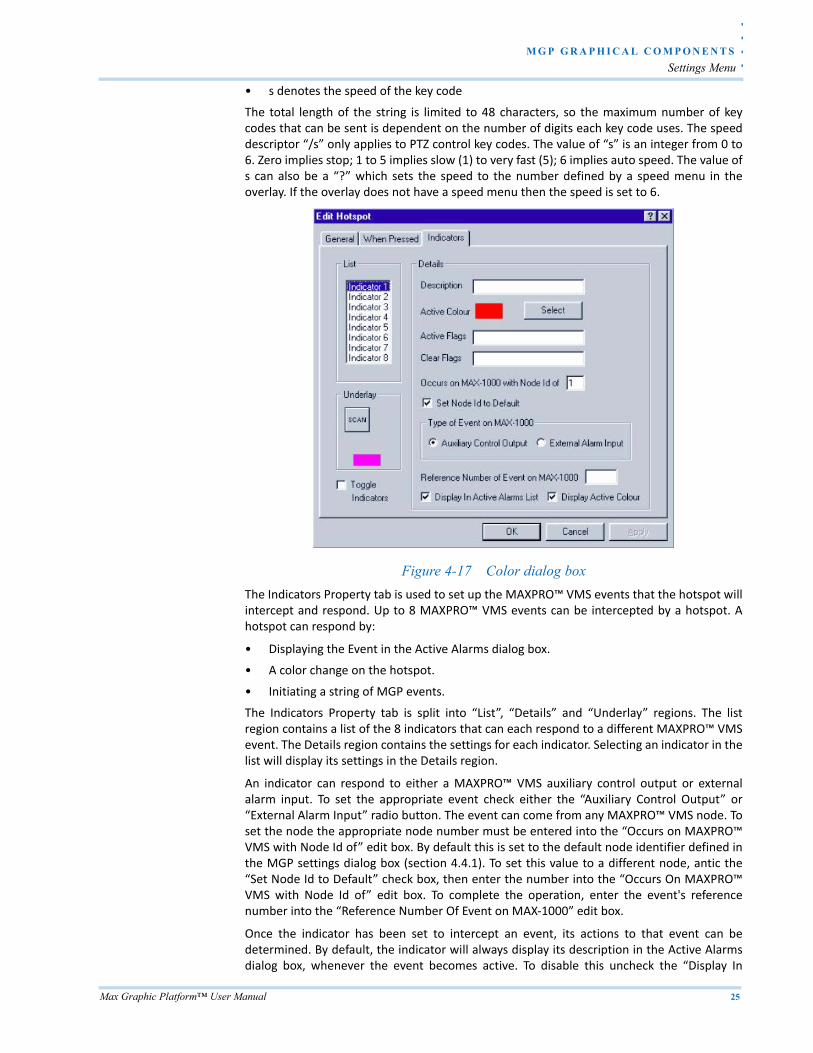
Figure 4-17 Color dialog box
The Indicators Property tab is used to set up the MAXPRO™ VMS events that the hotspot willintercept and respond. Up to 8 MAXPRO™ VMS events can be intercepted by a hotspot. Ahotspot can respond by:
• Displaying the Event in the Active Alarms dialog box.
• A color change on the hotspot.
• Initiating a string of MGP events.
The Indicators Property tab is split into “List”, “Details” and “Underlay” regions. The listregion contains a list of the 8 indicators that can each respond to a different MAXPRO™ VMSevent. The Details region contains the settings for each indicator. Selecting an indicator in thelist will display its settings in the Details region.
An indicator can respond to either a MAXPRO™ VMS auxiliary control output or externalalarm input. To set the appropriate event check either the “Auxiliary Control Output” or“External Alarm Input” radio button. The event can come from any MAXPRO™ VMS node. Toset the node the appropriate node number must be entered into the “Occurs on MAXPRO™VMS with Node Id of” edit box. By default this is set to the default node identifier defined inthe MGP settings dialog box (section 4.4.1). To set this value to a different node, antic the“Set Node Id to Default” check box, then enter the number into the “Occurs On MAXPRO™VMS with Node Id of” edit box. To complete the operation, enter the event's referencenumber into the “Reference Number Of Event on MAX‐1000” edit box.
Once the indicator has been set to intercept an event, its actions to that event can bedetermined. By default, the indicator will always display its description in the Active Alarmsdialog box, whenever the event becomes active. To disable this uncheck the “Display In
M G P G R A P H I C A L C O M P O N E N T S
Settings Menu
26 Max Graphic Platform™ User Manual
4
Active Alarms List” check box. To initiate any MGP events the appropriate MGP flags must beentered into the “Active Flags” or “Clear Flags” edit boxes. Active flags are initiated when theevent becomes active. Clear flags are initiated when the event becomes inactive.
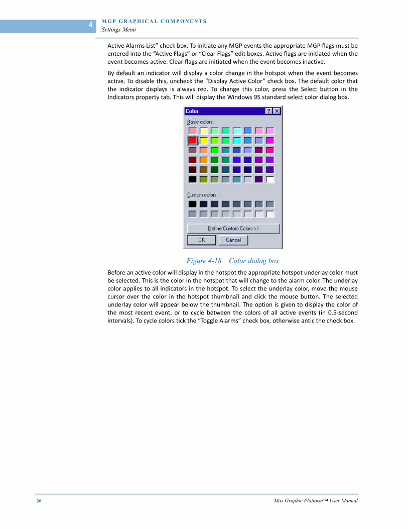
By default an indicator will display a color change in the hotspot when the event becomesactive. To disable this, uncheck the “Display Active Color” check box. The default color thatthe indicator displays is always red. To change this color, press the Select button in theIndicators property tab. This will display the Windows 95 standard select color dialog box.
Figure 4-18 Color dialog box
Before an active color will display in the hotspot the appropriate hotspot underlay color mustbe selected. This is the color in the hotspot that will change to the alarm color. The underlaycolor applies to all indicators in the hotspot. To select the underlay color, move the mousecursor over the color in the hotspot thumbnail and click the mouse button. The selectedunderlay color will appear below the thumbnail. The option is given to display the color ofthe most recent event, or to cycle between the colors of all active events (in 0.5‐secondintervals). To cycle colors tick the “Toggle Alarms” check box, otherwise antic the check box.
. .
. .
.
M G P G R A P H I C A L C O M P O N E N T S
Settings Menu
Max Graphic Platform™ User Manual 27
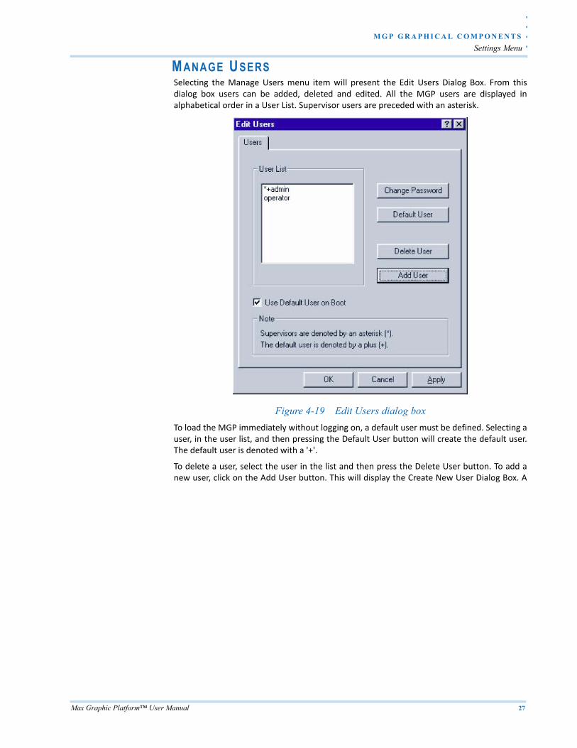
MANAGE U SERSSelecting the Manage Users menu item will present the Edit Users Dialog Box. From thisdialog box users can be added, deleted and edited. All the MGP users are displayed inalphabetical order in a User List. Supervisor users are preceded with an asterisk.
Figure 4-19 Edit Users dialog box
To load the MGP immediately without logging on, a default user must be defined. Selecting auser, in the user list, and then pressing the Default User button will create the default user.The default user is denoted with a '+'.
To delete a user, select the user in the list and then press the Delete User button. To add anew user, click on the Add User button. This will display the Create New User Dialog Box. A
M G P G R A P H I C A L C O M P O N E N T S
Settings Menu
28 Max Graphic Platform™ User Manual
4
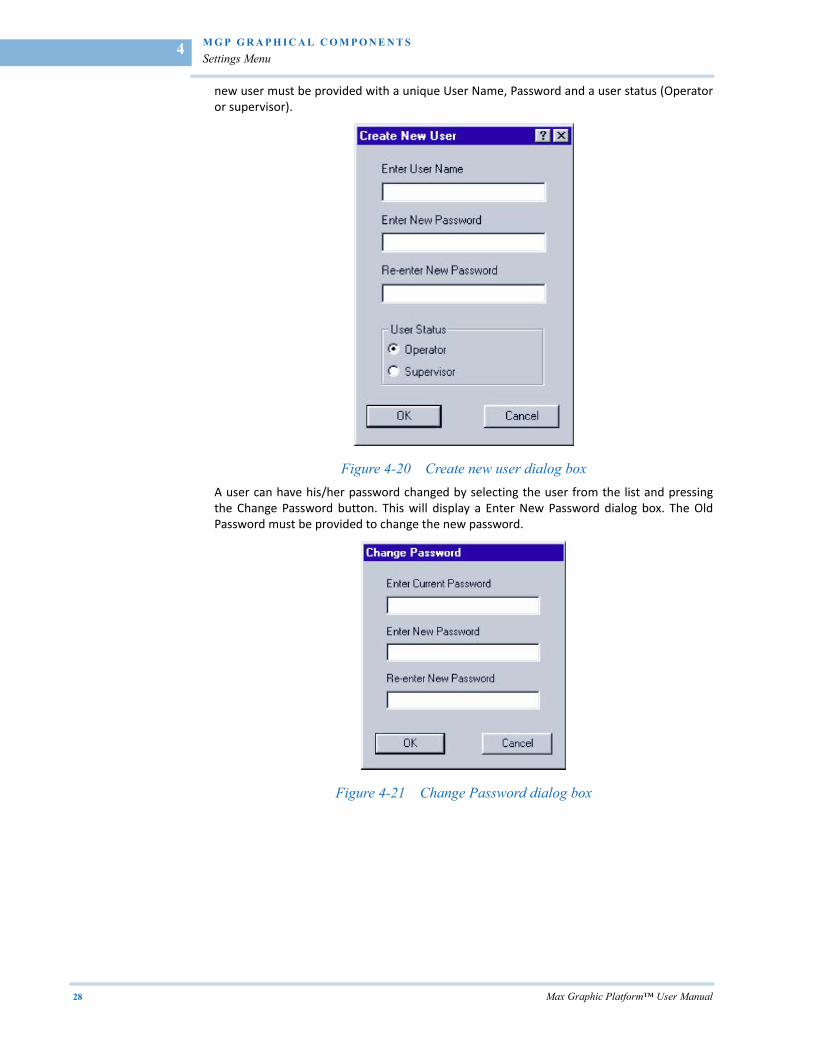
new user must be provided with a unique User Name, Password and a user status (Operatoror supervisor).
Figure 4-20 Create new user dialog box
A user can have his/her password changed by selecting the user from the list and pressingthe Change Password button. This will display a Enter New Password dialog box. The OldPassword must be provided to change the new password.
Figure 4-21 Change Password dialog box
. .
. .
.
M G P G R A P H I C A L C O M P O N E N T S
Hot Spot Menu
Max Graphic Platform™ User Manual 29
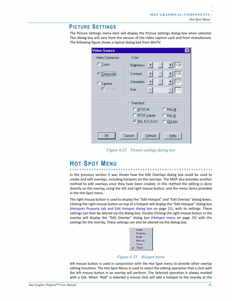
PICTURE S ETTINGS The Picture Settings menu item will display the Picture Settings dialog box when selected.This dialog box will vary from the version of the video capture card and from manufacture.The following figure shows a typical dialog box from WinTV.
Figure 4-22 Picture settings dialog box
. . . . . . . . . . . . . . . . . . . . . . . . . . . . . . . . . . . . . . . . . . . . . . . . . . . . . . . . . . .HOT SPOT MENU
In the previous section it was shown how the Edit Overlays dialog box could be used tocreate and edit overlays, including hotspots on the overlays. The MGP also provides anothermethod to edit overlays once they have been created. In this method the editing is donedirectly on the overlay, using the left and right mouse button, and the menu items providedin the Hot Spot menu.
The right mouse button is used to display the “Edit Hotspot” and “Edit Overlay” dialog boxes.Clicking the right mouse button on top of a hotspot will display the “Edit Hotspot” dialog box(Hotspots Property tab and Edit Hotspot dialog box on page 21), with its settings. Thesesettings can then be altered via the dialog box. Double Clicking the right mouse button in theoverlay will display the “Edit Overlay” dialog box (Hotspot menu on page 29) with thesettings for the overlay. These settings can also be altered via the dialog box.
Figure 4-23 Hotspot menu
left mouse button is used in conjunction with the Hot Spot menu to provide other overlayediting functions. The Hot Spot Menu is used to select the editing operation that a click withthe left mouse button in an overlay will perform. The Selected operation is always markedwith a tick. When “Add” is selected a mouse click will add a hotspot to the overlay at the
M G P G R A P H I C A L C O M P O N E N T S
Help menu
30 Max Graphic Platform™ User Manual
4
position of the click. When “Delete” is selected, a mouse click on a hotspot will delete it fromthe overlay. “Edit” will make the left mouse button behave like the right mouse button.“Move” enables the left mouse button to drag a hotspot to a new position in the overlay. Adrag involves holding down the mouse button on a hotspot, moving the mouse to a newlocation, then releasing the mouse button. The “Size” menu item allows hotspots to be re‐sized by using the drag method. Finally, “Test” enables the mouse to operate as if in operatormode. That is, a press on a hotspot will activate the events set up on a hotspot press.
. . . . . . . . . . . . . . . . . . . . . . . . . . . . . . . . . . . . . . . . . . . . . . . . . . . . . . . . . . .HELP MENU
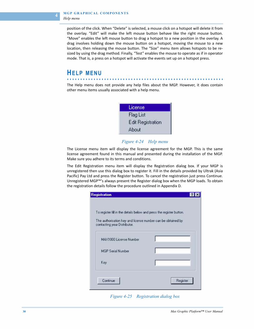
The Help menu does not provide any help files about the MGP. However, it does containother menu items usually associated with a help menu.
Figure 4-24 Help menu
The License menu item will display the license agreement for the MGP. This is the samelicense agreement found in this manual and presented during the installation of the MGP.Make sure you adhere to its terms and conditions.
The Edit Registration menu item will display the Registration dialog box. If your MGP isunregistered then use this dialog box to register it. Fill in the details provided by Ultrak (AsiaPacific) Pay Ltd and press the Register button. To cancel the registration just press Continue.Unregistered MGP™'s always present the Register dialog box when the MGP loads. To obtainthe registration details follow the procedure outlined in Appendix D.
Figure 4-25 Registration dialog box
. .
. .
.
M G P G R A P H I C A L C O M P O N E N T S
Help menu
Max Graphic Platform™ User Manual 31
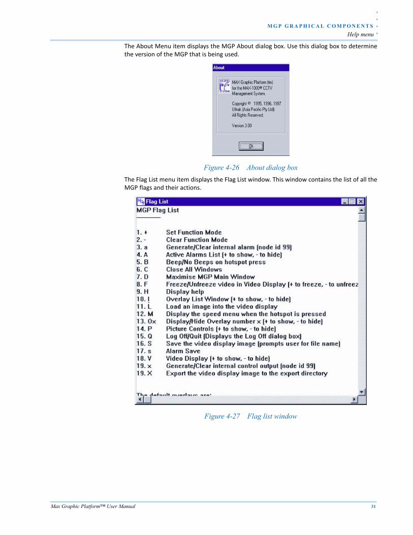
The About Menu item displays the MGP About dialog box. Use this dialog box to determinethe version of the MGP that is being used.
Figure 4-26 About dialog box
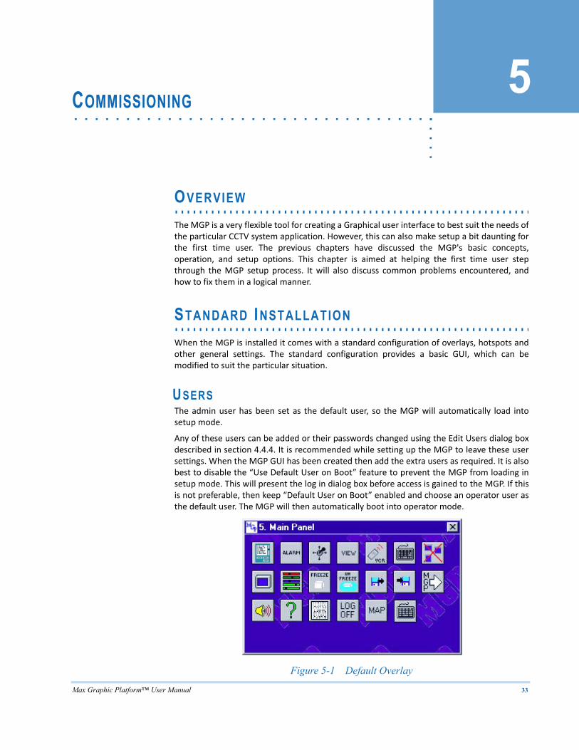
The Flag List menu item displays the Flag List window. This window contains the list of all theMGP flags and their actions.
Figure 4-27 Flag list window

Max Graphic Platform™ User Manual 33
5. . . . .
. . . . . . . . . . . . . . . . . . . . . . . . . . . . . . . . . . .COMMISSIONING
. . . . . . . . . . . . . . . . . . . . . . . . . . . . . . . . . . . . . . . . . . . . . . . . . . . . . . . . . . .OVERVIEW
The MGP is a very flexible tool for creating a Graphical user interface to best suit the needs ofthe particular CCTV system application. However, this can also make setup a bit daunting forthe first time user. The previous chapters have discussed the MGP's basic concepts,operation, and setup options. This chapter is aimed at helping the first time user stepthrough the MGP setup process. It will also discuss common problems encountered, andhow to fix them in a logical manner.
. . . . . . . . . . . . . . . . . . . . . . . . . . . . . . . . . . . . . . . . . . . . . . . . . . . . . . . . . . .STANDARD INSTALLATION
When the MGP is installed it comes with a standard configuration of overlays, hotspots andother general settings. The standard configuration provides a basic GUI, which can bemodified to suit the particular situation.
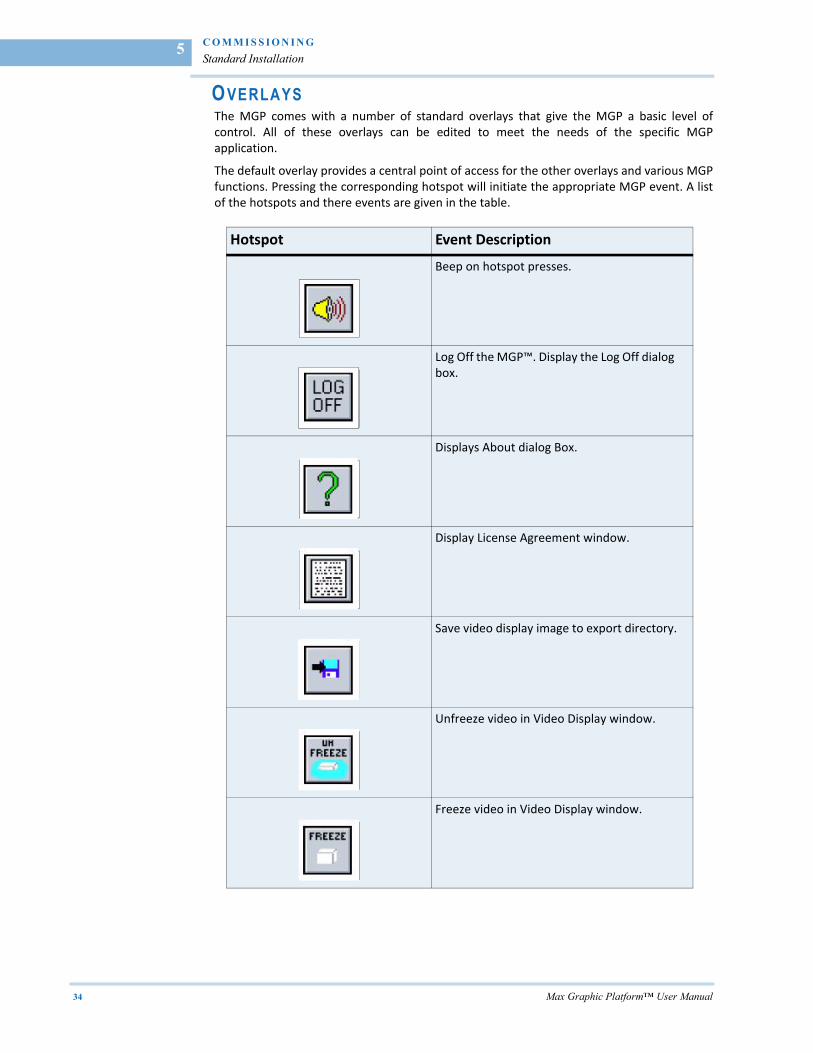
USERS The admin user has been set as the default user, so the MGP will automatically load intosetup mode.
Any of these users can be added or their passwords changed using the Edit Users dialog boxdescribed in section 4.4.4. It is recommended while setting up the MGP to leave these usersettings. When the MGP GUI has been created then add the extra users as required. It is alsobest to disable the “Use Default User on Boot” feature to prevent the MGP from loading insetup mode. This will present the log in dialog box before access is gained to the MGP. If thisis not preferable, then keep “Default User on Boot” enabled and choose an operator user asthe default user. The MGP will then automatically boot into operator mode.
Figure 5-1 Default Overlay
C O M M I S S I O N I N G
Standard Installation
34 Max Graphic Platform™ User Manual
5
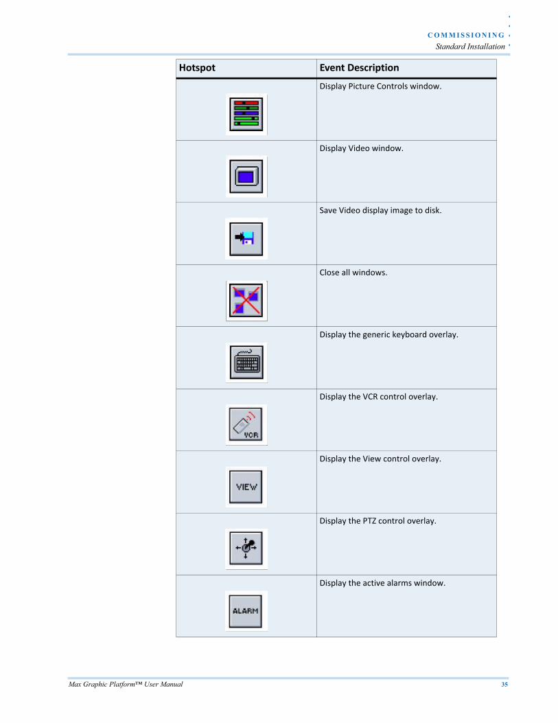
OVERLAYS The MGP comes with a number of standard overlays that give the MGP a basic level ofcontrol. All of these overlays can be edited to meet the needs of the specific MGPapplication.
The default overlay provides a central point of access for the other overlays and various MGPfunctions. Pressing the corresponding hotspot will initiate the appropriate MGP event. A listof the hotspots and there events are given in the table.
Hotspot Event Description
Beep on hotspot presses.
Log Off the MGP™. Display the Log Off dialog box.
Displays About dialog Box.
Display License Agreement window.
Save video display image to export directory.
Unfreeze video in Video Display window.
Freeze video in Video Display window.
. .
. .
.
C O M M I S S I O N I N G
Standard Installation
Max Graphic Platform™ User Manual 35
Display Picture Controls window.
Display Video window.
Save Video display image to disk.
Close all windows.
Display the generic keyboard overlay.
Display the VCR control overlay.
Display the View control overlay.
Display the PTZ control overlay.
Display the active alarms window.
Hotspot Event Description
C O M M I S S I O N I N G
Standard Installation
36 Max Graphic Platform™ User Manual
5
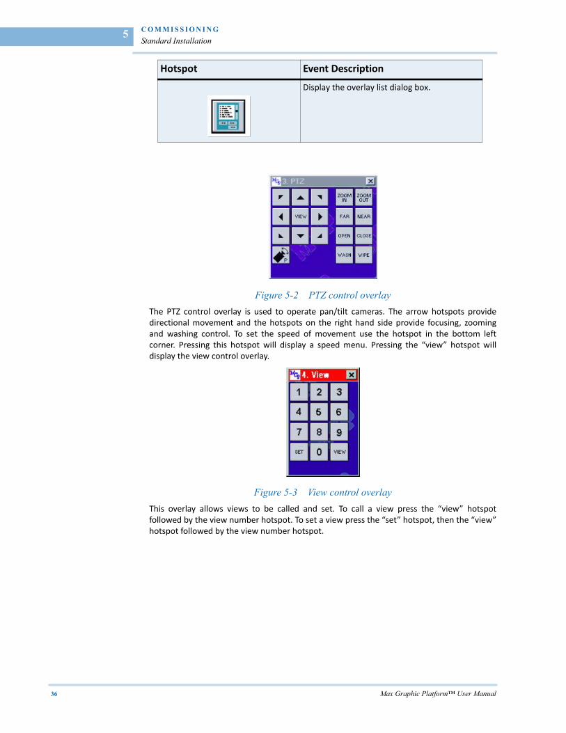
Figure 5-2 PTZ control overlay
The PTZ control overlay is used to operate pan/tilt cameras. The arrow hotspots providedirectional movement and the hotspots on the right hand side provide focusing, zoomingand washing control. To set the speed of movement use the hotspot in the bottom leftcorner. Pressing this hotspot will display a speed menu. Pressing the “view” hotspot willdisplay the view control overlay.
Figure 5-3 View control overlay
This overlay allows views to be called and set. To call a view press the “view” hotspotfollowed by the view number hotspot. To set a view press the “set” hotspot, then the “view”hotspot followed by the view number hotspot.
Display the overlay list dialog box.
Hotspot Event Description
. .
. .
.
C O M M I S S I O N I N G
Standard Installation
Max Graphic Platform™ User Manual 37
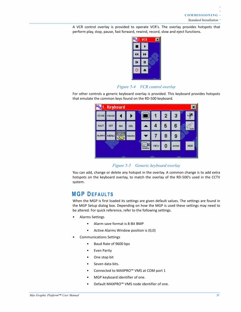
A VCR control overlay is provided to operate VCR's. The overlay provides hotspots thatperform play, stop, pause, fast forward, rewind, record, slow and eject functions.
Figure 5-4 VCR control overlay
For other controls a generic keyboard overlay is provided. This keyboard provides hotspotsthat emulate the common keys found on the RD‐500 keyboard.
Figure 5-5 Generic keyboard overlay
You can add, change or delete any hotspot in the overlay. A common change is to add extrahotspots on the keyboard overlay, to match the overlay of the RD‐500's used in the CCTVsystem.
MGP D EFAULTS When the MGP is first loaded its settings are given default values. The settings are found inthe MGP Setup dialog box. Depending on how the MGP is used these settings may need tobe altered. For quick reference, refer to the following settings.
• Alarms Settings
• Alarm save format is 8‐Bit BMP
• Active Alarms Window position is (0,0)
• Communications Settings
• Baud Rate of 9600 bps
• Even Parity
• One stop bit
• Seven data bits.
• Connected to MAXPRO™ VMS at COM port 1
• MGP keyboard identifier of one.
• Default MAXPRO™ VMS node identifier of one.
C O M M I S S I O N I N G
Basic Setup Guide
38 Max Graphic Platform™ User Manual
5
• Directories
• MGP Directory is the directory where the MGP was installed.
• Overlay Directory is a directory called overlays that exists in the MGP directory
• Hotspot Directory is a directory called hotspots that exists in the MGP directory
• Image Directory is a directory called images that exists in the MGP directory
• Export Directory is a directory called export that exists in the MGP directory
• Alarm Directory is a directory called alarms that exists in the MGP directory
• Miscellaneous
• Save Window Defaults on Exit is disabled
• Prevent Quitting the MGP is disabled
• Video Display Always on Top is disabled
• Lock All Window Positions is disabled
Changing these settings depends on various factors. It is common to change thecommunications settings. If the computer has a serial mouse then the COM port should bechanged to 2. (The mouse is usually on COM port1). Often the keyboard identifier of one isalready used on the MAX‐1000. If this is the case it will need to be changed to anothernumber. These considerations will be discussed in greater detail later in this chapter.
. . . . . . . . . . . . . . . . . . . . . . . . . . . . . . . . . . . . . . . . . . . . . . . . . . . . . . . . . . .BASIC SETUP GUIDE
Once the MGP is installed a number of steps must be taken to setup the MGP so that itoperates to the appropriate requirements. This section will step through the basic process ofcontrolling a MAXPRO™ VMS with the default MGP installation.
CONFIGURING THE MAXPRO™ VMS The first step in setting up an MGP is to ensure it is connected and communicating with aMAXPRO™ VMS. This is the most difficult step in the MGP setup as there are so manyvariables to consider. However, if the correct process is followed problems can be isolatedvery quickly.
To start a port must be defined on the MAXPRO™ VMS MAXPRO™ VMS that will be used forthe MGP. Select an undefined entry and define it as a network port. Also set the baud rate inthe “BAUD” field and the other RS‐232 settings in the “CTRL” field. Make a note of thesesettings, as they must be identically defined on the MGP.
If the MGP uses an external monitor to display video, or has video capture card installed,then the video output channel of this monitor must be defined on the MAXPRO™ VMS. It isassumed that the hardware for the video channel is installed. For more information, see theMAXPRO™ VMS commissioning manual.
On the MAXPRO™ VMS a user must also be defined, for use by the MGP. Do not confuse thisuser with MGP users. MGP users determine access to the MGP's setup and operator modes.The user defined on the MAXPRO™ VMS determines to access the MGP, regardless of whichMGP user is operating the MGP.
Note: The node number used by all MGP's is "99".
. .
. .
.
C O M M I S S I O N I N G
Basic Setup Guide
Max Graphic Platform™ User Manual 39
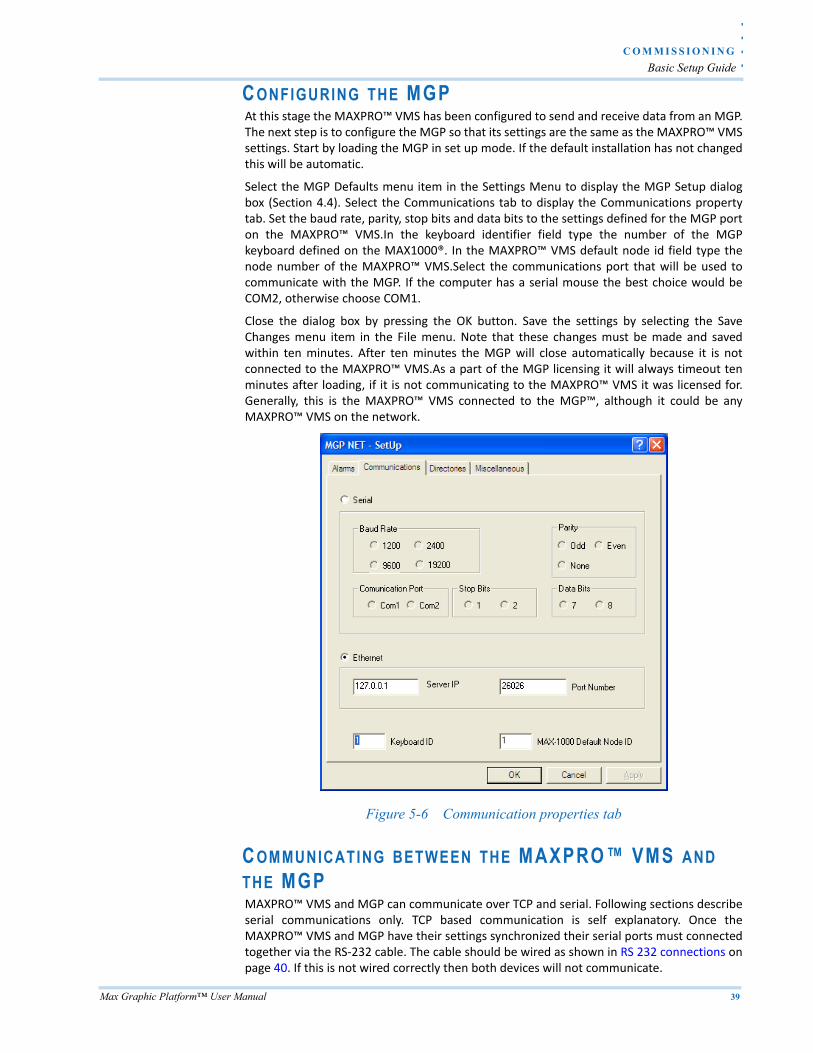
CONFIGURING THE MGP At this stage the MAXPRO™ VMS has been configured to send and receive data from an MGP.The next step is to configure the MGP so that its settings are the same as the MAXPRO™ VMSsettings. Start by loading the MGP in set up mode. If the default installation has not changedthis will be automatic.
Select the MGP Defaults menu item in the Settings Menu to display the MGP Setup dialogbox (Section 4.4). Select the Communications tab to display the Communications propertytab. Set the baud rate, parity, stop bits and data bits to the settings defined for the MGP porton the MAXPRO™ VMS.In the keyboard identifier field type the number of the MGPkeyboard defined on the MAX1000®. In the MAXPRO™ VMS default node id field type thenode number of the MAXPRO™ VMS.Select the communications port that will be used tocommunicate with the MGP. If the computer has a serial mouse the best choice would beCOM2, otherwise choose COM1.
Close the dialog box by pressing the OK button. Save the settings by selecting the SaveChanges menu item in the File menu. Note that these changes must be made and savedwithin ten minutes. After ten minutes the MGP will close automatically because it is notconnected to the MAXPRO™ VMS.As a part of the MGP licensing it will always timeout tenminutes after loading, if it is not communicating to the MAXPRO™ VMS it was licensed for.Generally, this is the MAXPRO™ VMS connected to the MGP™, although it could be anyMAXPRO™ VMS on the network.
Figure 5-6 Communication properties tab
COMMUNICATING BETWEEN THE MAXPRO™ VMS AND THE MGP MAXPRO™ VMS and MGP can communicate over TCP and serial. Following sections describeserial communications only. TCP based communication is self explanatory. Once theMAXPRO™ VMS and MGP have their settings synchronized their serial ports must connectedtogether via the RS‐232 cable. The cable should be wired as shown in RS 232 connections onpage 40. If this is not wired correctly then both devices will not communicate.
C O M M I S S I O N I N G
Basic Setup Guide
40 Max Graphic Platform™ User Manual
5
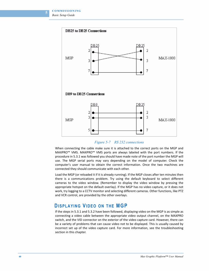
Figure 5-7 RS 232 connections
When connecting the cable make sure it is attached to the correct ports on the MGP andMAXPRO™ VMS. MAXPRO™ VMS ports are always labeled with the port numbers. If theprocedure in 5.3.1 was followed you should have made note of the port number the MGP willuse. The MGP serial ports may vary depending on the model of computer. Check thecomputer's user manual to obtain the correct information. Once the two machines areconnected they should communicate with each other.
Load the MGP (or reloaded it if it is already running). If the MGP closes after ten minutes thenthere is a communications problem. Try using the default keyboard to select differentcameras to the video window. (Remember to display the video window by pressing theappropriate hotspot on the default overlay). If the MGP has no video capture, or it does notwork, try logging to a CCTV monitor and selecting different cameras. Other functions, like PTZand VCR control, are provided by the other overlays.
DISPLAYING V IDEO ON THE MGP If the steps in 5.3.1 and 5.3.2 have been followed, displaying video on the MGP is as simple asconnecting a video cable between the appropriate video output channel, on the MAXPROswitch, and the VID connector on the exterior of the video capture card. However, there canbe a variety of problems that can cause video not to be displayed. This is usually caused byincorrect set up of the video capture card. For more information, see the troubleshootingsection in this chapter.
. .
. .
.
C O M M I S S I O N I N G
Advanced Setup Guide
Max Graphic Platform™ User Manual 41
. . . . . . . . . . . . . . . . . . . . . . . . . . . . . . . . . . . . . . . . . . . . . . . . . . . . . . . . . . .ADVANCED SETUP GUIDE
Once the MGP is operating correctly with the MAXPRO™ VMS the GUI can be customized tothe needs of the CCTV application. Any of the features discussed in section 4.0 can beimplemented with relative ease. This section will step through the process of creating anoverlay that contains hotspots used for a range of tasks, including display of alarms, andgenerating events. It will also discuss how to use special hotspot features, such as invisiblehotspots and transparenting. It is assumed that the MGP can communicate with a MAXPRO™VMS and that it has all the default overlays installed. The bitmaps used are provided with thedefault installation and can be located in the default hotspot and overlay directories. To stepthrough the tasks the MGP must be in set up mode. If the MGP is not in set up mode then logon to the MGP as a supervisor user. For a complete discussion of the MGP's setup featuresplease refer to chapter 4.
CREATING AN OVERLAY The overlay in this example will represent a room with a door as its only point of entry. Thedoor has a device attached that can notify a MAXPRO™ VMS when someone is requestingaccess. The door can also be opened or closed by a signal generated from the MAXPRO™VMS. The room also contains a fixed camera and a PTZ camera. Both cameras are attached tothe MAXPRO™ VMS matrix and can be selected/controlled from the MAXPRO™ VMS. Pleasenote that the scenario presented is only used to illustrate the MGP's features. It is only anidealized look at a real life scenario and might not operate correctly in a real life situation.
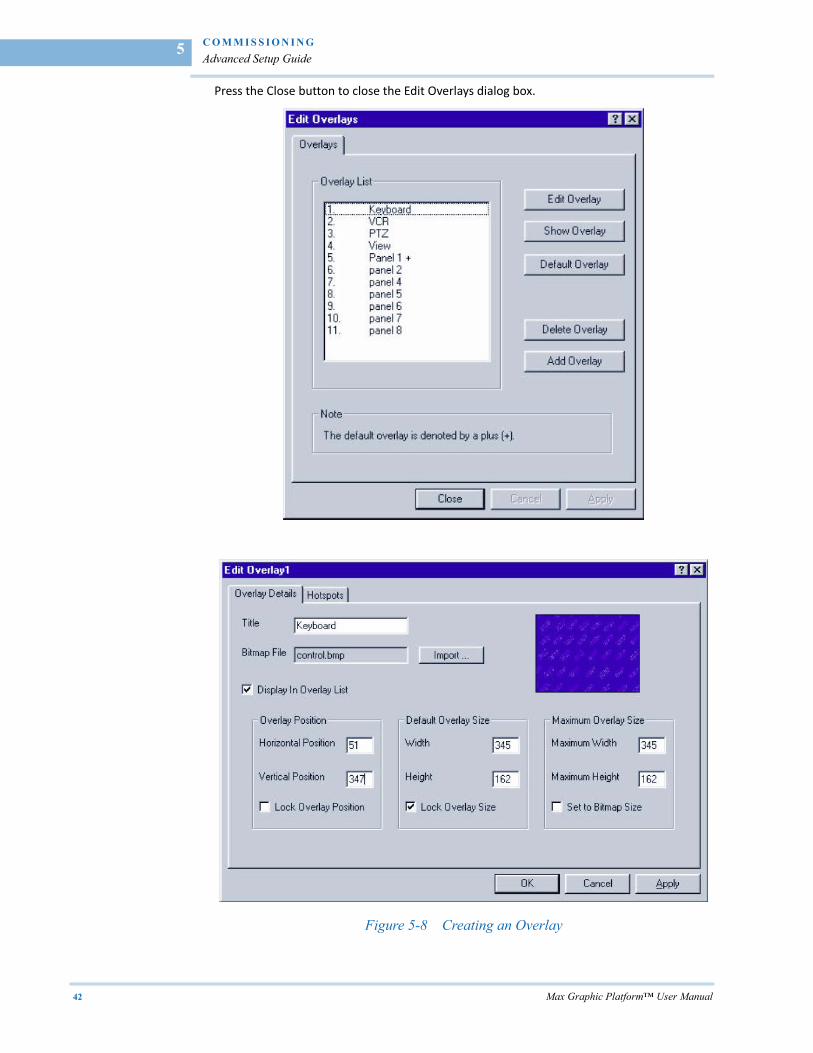
An overlay is created by using the Edit Overlays dialog box. To display this dialog box selectthe Edit Overlays menu item found in the settings menu (See Creating an Overlay on page42). To add the overlay press the Add Overlay button. This will display the Edit OverlaysDialog box, which is used to enter the overlays properties. The first step is to give the overlaya title. In the Title edit box type “Room 1". This title will be used to describe the overlay somake sure it is appropriate. The next step is to select a background bitmap for the overlay.Press the import button to display the Import bitmap dialog box. This dialog box enablesnavigation of the computer's directory structure to locate the appropriate bitmap file toimport. In this example the bitmap file called “Room1.bmp” must be imported. The bitmap islocated inside the MGP directory in a directory called “overlays”. Selecting this directory inthe Directories tree will display the bitmap in the Bitmap Files list box. Select the bitmap andpress the import button. The Import Bitmap dialog box will disappear and user focus willreturn to the Edit overlay dialog box. Notice that the thumbnail in this dialog box nowdisplays the “Room1.bmp” bitmap.
It is often desirable to set the maximum size of the overlay to the size of the bitmap. Toperform this task tick the “Set to Bitmap Size” dialog box. For other settings refer to EditOverlays section in Chapter 4, otherwise press the OK button. At this point the overlay hasbeen created and is displayed in the Edit Overlays dialog box.
C O M M I S S I O N I N G
Advanced Setup Guide
42 Max Graphic Platform™ User Manual
5
Press the Close button to close the Edit Overlays dialog box.
Figure 5-8 Creating an Overlay
. .
. .
.
C O M M I S S I O N I N G
Advanced Setup Guide
Max Graphic Platform™ User Manual 43
ADDING H OTSPOTS TO AN OVERLAY The next step in creating an overlay is to add hotspots. The MGP has two methods tocomplete this task. Refer to Edit Overlays and Hotspot Menu sections in Chapter 4. Theeasiest method is to use the mouse to add hotspots directly onto the overlay.
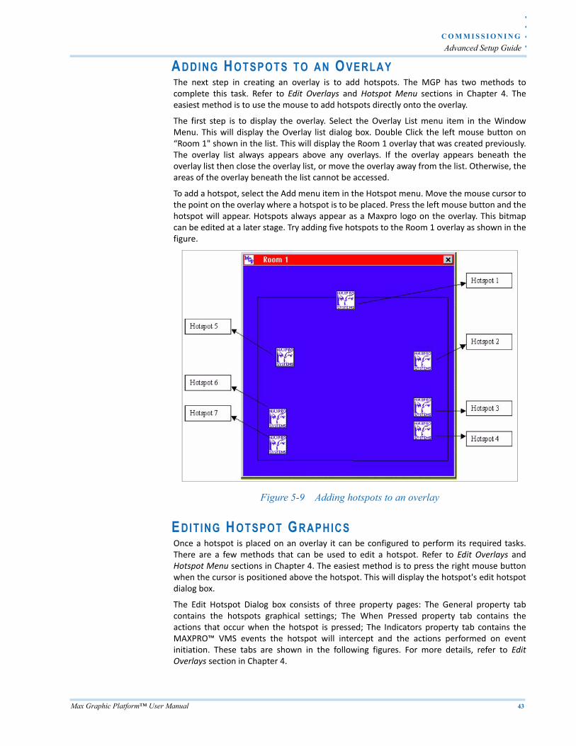
The first step is to display the overlay. Select the Overlay List menu item in the WindowMenu. This will display the Overlay list dialog box. Double Click the left mouse button on“Room 1" shown in the list. This will display the Room 1 overlay that was created previously.The overlay list always appears above any overlays. If the overlay appears beneath theoverlay list then close the overlay list, or move the overlay away from the list. Otherwise, theareas of the overlay beneath the list cannot be accessed.
To add a hotspot, select the Add menu item in the Hotspot menu. Move the mouse cursor tothe point on the overlay where a hotspot is to be placed. Press the left mouse button and thehotspot will appear. Hotspots always appear as a Maxpro logo on the overlay. This bitmapcan be edited at a later stage. Try adding five hotspots to the Room 1 overlay as shown in thefigure.
Figure 5-9 Adding hotspots to an overlay
EDITING H OTSPOT GRAPHICS Once a hotspot is placed on an overlay it can be configured to perform its required tasks.There are a few methods that can be used to edit a hotspot. Refer to Edit Overlays andHotspot Menu sections in Chapter 4. The easiest method is to press the right mouse buttonwhen the cursor is positioned above the hotspot. This will display the hotspot's edit hotspotdialog box.
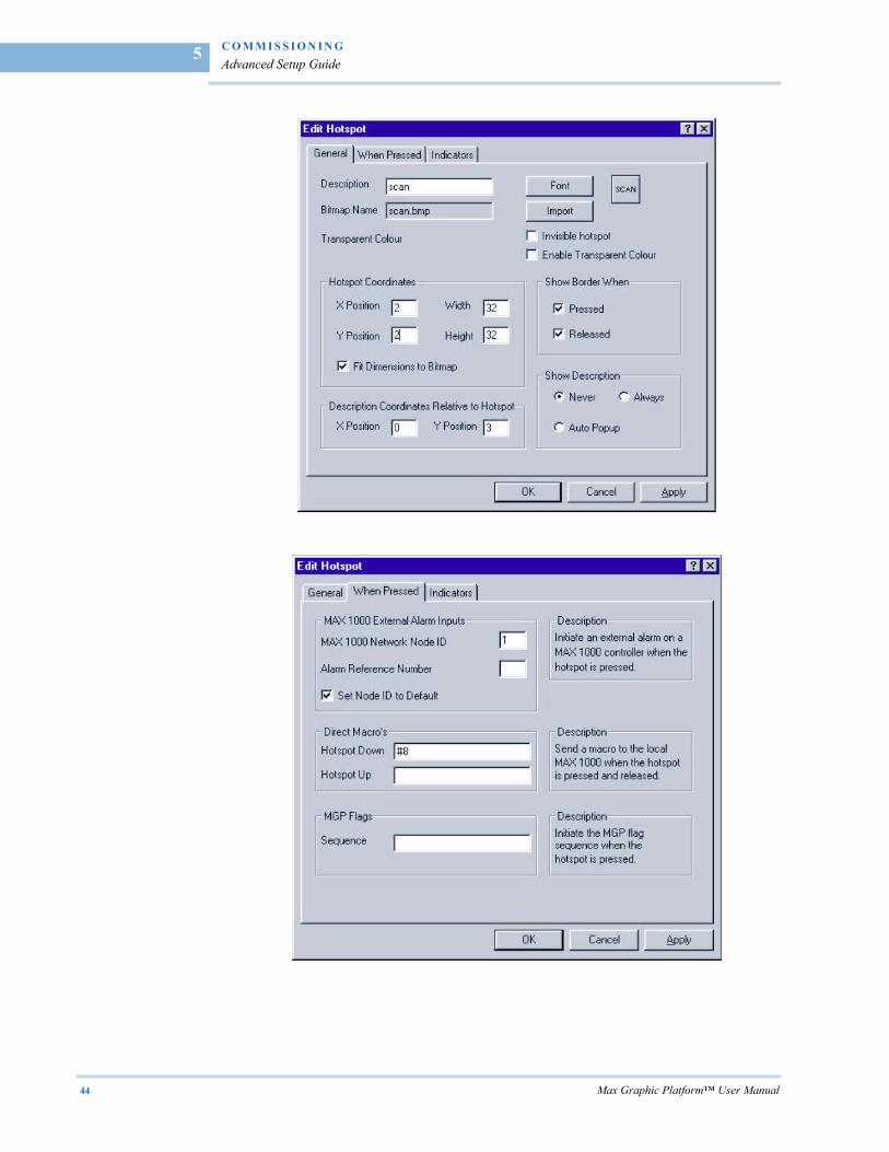
The Edit Hotspot Dialog box consists of three property pages: The General property tabcontains the hotspots graphical settings; The When Pressed property tab contains theactions that occur when the hotspot is pressed; The Indicators property tab contains theMAXPRO™ VMS events the hotspot will intercept and the actions performed on eventinitiation. These tabs are shown in the following figures. For more details, refer to EditOverlays section in Chapter 4.
C O M M I S S I O N I N G
Advanced Setup Guide
44 Max Graphic Platform™ User Manual
5
. .
. .
.
C O M M I S S I O N I N G
Advanced Setup Guide
Max Graphic Platform™ User Manual 45
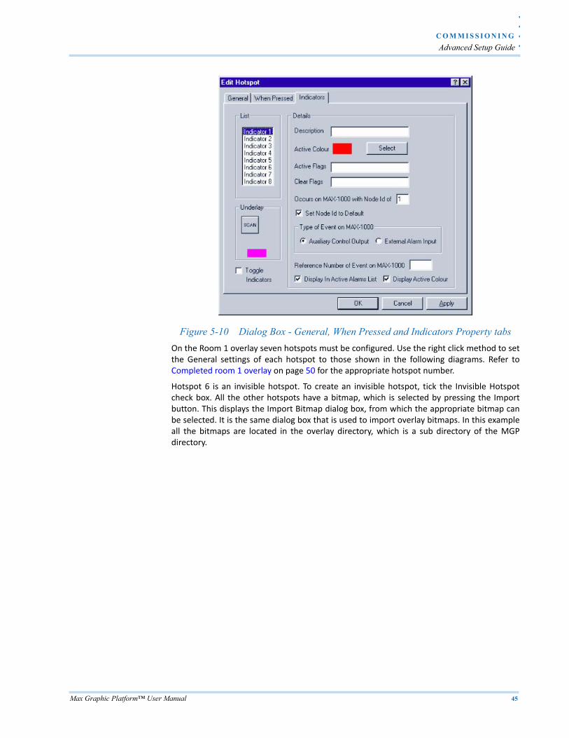
Figure 5-10 Dialog Box - General, When Pressed and Indicators Property tabs
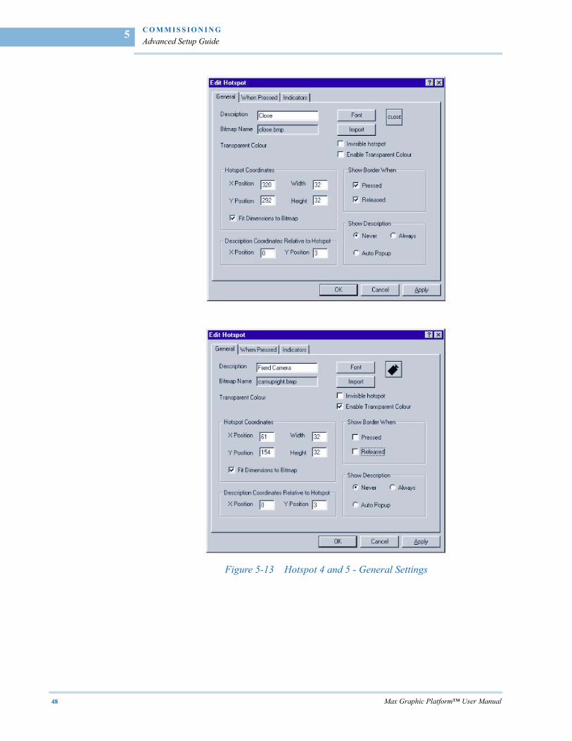
On the Room 1 overlay seven hotspots must be configured. Use the right click method to setthe General settings of each hotspot to those shown in the following diagrams. Refer toCompleted room 1 overlay on page 50 for the appropriate hotspot number.
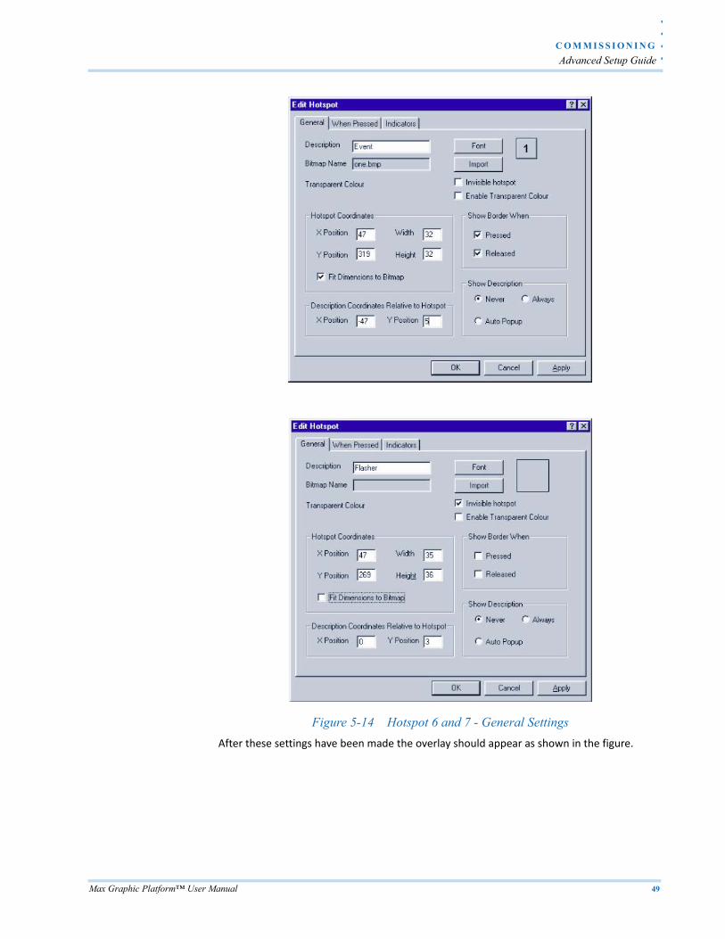
Hotspot 6 is an invisible hotspot. To create an invisible hotspot, tick the Invisible Hotspotcheck box. All the other hotspots have a bitmap, which is selected by pressing the Importbutton. This displays the Import Bitmap dialog box, from which the appropriate bitmap canbe selected. It is the same dialog box that is used to import overlay bitmaps. In this exampleall the bitmaps are located in the overlay directory, which is a sub directory of the MGPdirectory.
C O M M I S S I O N I N G
Advanced Setup Guide
46 Max Graphic Platform™ User Manual
5
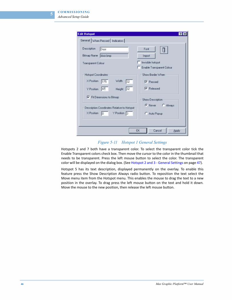
Figure 5-11 Hotspot 1 General Settings
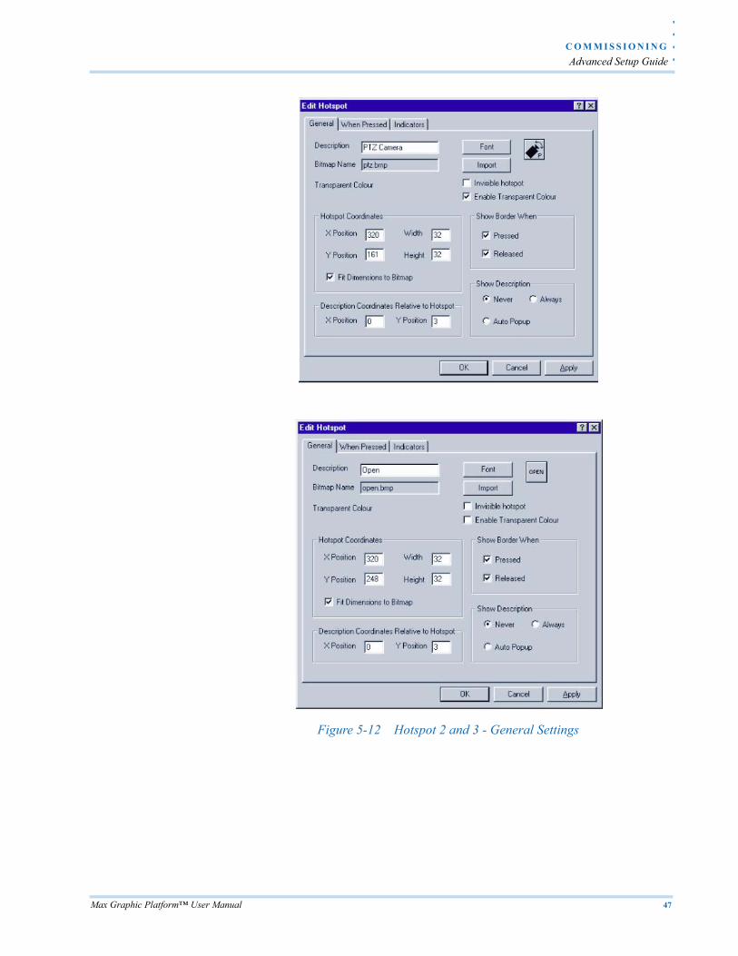
Hotspots 2 and 7 both have a transparent color. To select the transparent color tick theEnable Transparent colors check box. Then move the cursor to the color in the thumbnail thatneeds to be transparent. Press the left mouse button to select the color. The transparentcolor will be displayed on the dialog box. (See Hotspot 2 and 3 ‐ General Settings on page 47).
Hotspot 5 has its text description, displayed permanently on the overlay. To enable thisfeature press the Show Description Always radio button. To reposition the text select theMove menu item from the Hotspot menu. This enables the mouse to drag the text to a newposition in the overlay. To drag press the left mouse button on the text and hold it down.Move the mouse to the new position, then release the left mouse button.
. .
. .
.
C O M M I S S I O N I N G
Advanced Setup Guide
Max Graphic Platform™ User Manual 47
Figure 5-12 Hotspot 2 and 3 - General Settings
C O M M I S S I O N I N G
Advanced Setup Guide
48 Max Graphic Platform™ User Manual
5
Figure 5-13 Hotspot 4 and 5 - General Settings
. .
. .
.
C O M M I S S I O N I N G
Advanced Setup Guide
Max Graphic Platform™ User Manual 49
Figure 5-14 Hotspot 6 and 7 - General Settings
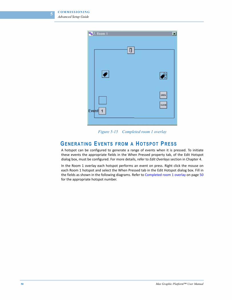
After these settings have been made the overlay should appear as shown in the figure.
C O M M I S S I O N I N G
Advanced Setup Guide
50 Max Graphic Platform™ User Manual
5
Figure 5-15 Completed room 1 overlay
GENERATING E VENTS FROM A HOTSPOT P RESS A hotspot can be configured to generate a range of events when it is pressed. To initiatethese events the appropriate fields in the When Pressed property tab, of the Edit Hotspotdialog box, must be configured. For more details, refer to Edit Overlays section in Chapter 4.
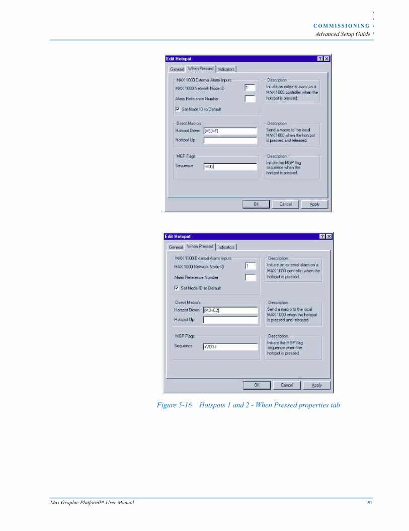
In the Room 1 overlay each hotspot performs an event on press. Right click the mouse oneach Room 1 hotspot and select the When Pressed tab in the Edit Hotspot dialog box. Fill inthe fields as shown in the following diagrams. Refer to Completed room 1 overlay on page 50for the appropriate hotspot number.
. .
. .
.
C O M M I S S I O N I N G
Advanced Setup Guide
Max Graphic Platform™ User Manual 51
Figure 5-16 Hotspots 1 and 2 - When Pressed properties tab
C O M M I S S I O N I N G
Advanced Setup Guide
52 Max Graphic Platform™ User Manual
5
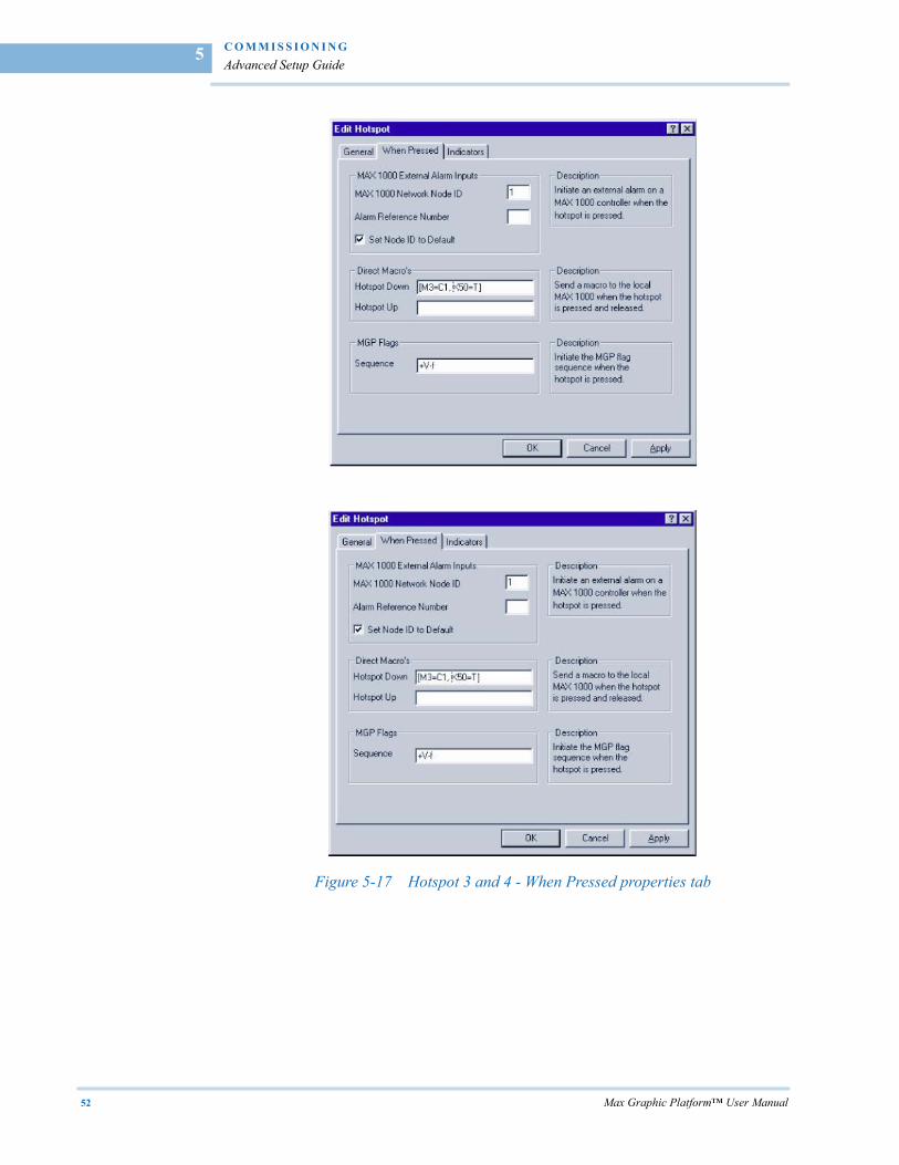
Figure 5-17 Hotspot 3 and 4 - When Pressed properties tab
. .
. .
.
C O M M I S S I O N I N G
Advanced Setup Guide
Max Graphic Platform™ User Manual 53
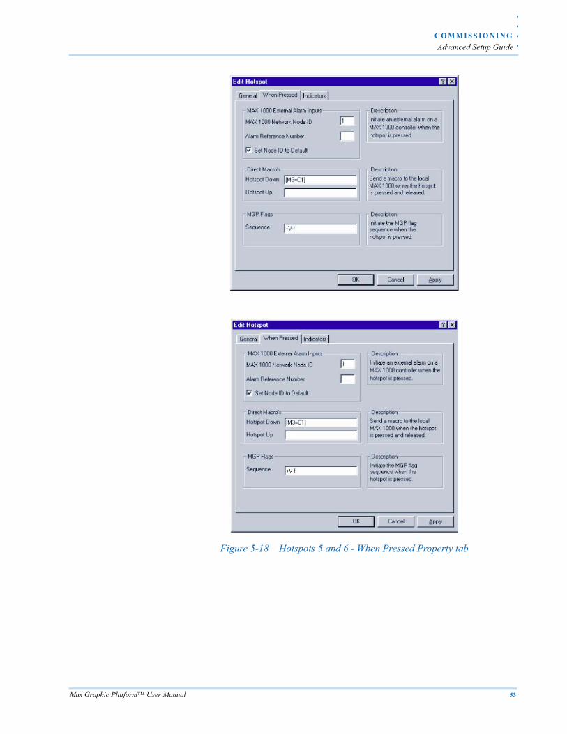
Figure 5-18 Hotspots 5 and 6 - When Pressed Property tab
C O M M I S S I O N I N G
Advanced Setup Guide
54 Max Graphic Platform™ User Manual
5
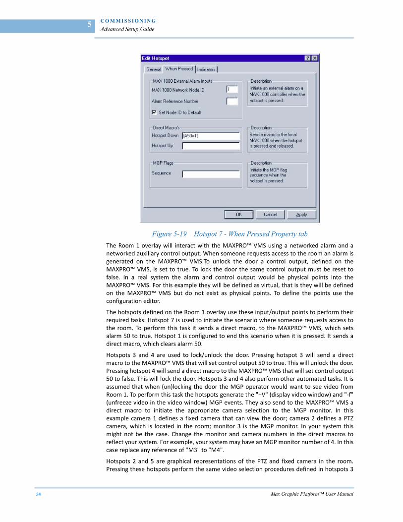
Figure 5-19 Hotspot 7 - When Pressed Property tab
The Room 1 overlay will interact with the MAXPRO™ VMS using a networked alarm and anetworked auxiliary control output. When someone requests access to the room an alarm isgenerated on the MAXPRO™ VMS.To unlock the door a control output, defined on theMAXPRO™ VMS, is set to true. To lock the door the same control output must be reset tofalse. In a real system the alarm and control output would be physical points into theMAXPRO™ VMS. For this example they will be defined as virtual, that is they will be definedon the MAXPRO™ VMS but do not exist as physical points. To define the points use theconfiguration editor.
The hotspots defined on the Room 1 overlay use these input/output points to perform theirrequired tasks. Hotspot 7 is used to initiate the scenario where someone requests access tothe room. To perform this task it sends a direct macro, to the MAXPRO™ VMS, which setsalarm 50 to true. Hotspot 1 is configured to end this scenario when it is pressed. It sends adirect macro, which clears alarm 50.
Hotspots 3 and 4 are used to lock/unlock the door. Pressing hotspot 3 will send a directmacro to the MAXPRO™ VMS that will set control output 50 to true. This will unlock the door.Pressing hotspot 4 will send a direct macro to the MAXPRO™ VMS that will set control output50 to false. This will lock the door. Hotspots 3 and 4 also perform other automated tasks. It isassumed that when (un)locking the door the MGP operator would want to see video fromRoom 1. To perform this task the hotspots generate the "+V" (display video window) and "‐f"(unfreeze video in the video window) MGP events. They also send to the MAXPRO™ VMS adirect macro to initiate the appropriate camera selection to the MGP monitor. In thisexample camera 1 defines a fixed camera that can view the door; camera 2 defines a PTZcamera, which is located in the room; monitor 3 is the MGP monitor. In your system thismight not be the case. Change the monitor and camera numbers in the direct macros toreflect your system. For example, your system may have an MGP monitor number of 4. In thiscase replace any reference of "M3" to "M4".
Hotspots 2 and 5 are graphical representations of the PTZ and fixed camera in the room.Pressing these hotspots perform the same video selection procedures defined in hotspots 3
. .
. .
.
C O M M I S S I O N I N G
Advanced Setup Guide
Max Graphic Platform™ User Manual 55
and 4. Hotspot 2 also initiates the "+O3" MGP event. This event displays the default overlaywhich has PTZ control functions, to allow the user fast access to pan/tilt control.
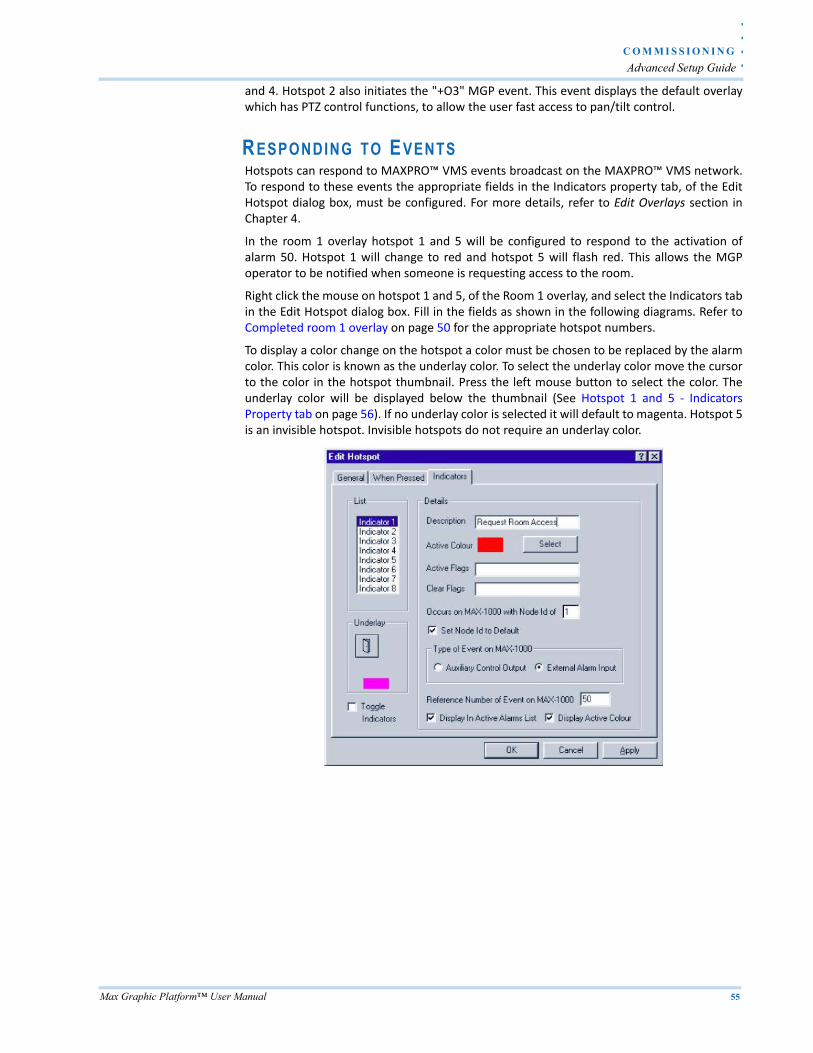
RESPONDING TO EVENTS Hotspots can respond to MAXPRO™ VMS events broadcast on the MAXPRO™ VMS network.To respond to these events the appropriate fields in the Indicators property tab, of the EditHotspot dialog box, must be configured. For more details, refer to Edit Overlays section inChapter 4.
In the room 1 overlay hotspot 1 and 5 will be configured to respond to the activation ofalarm 50. Hotspot 1 will change to red and hotspot 5 will flash red. This allows the MGPoperator to be notified when someone is requesting access to the room.
Right click the mouse on hotspot 1 and 5, of the Room 1 overlay, and select the Indicators tabin the Edit Hotspot dialog box. Fill in the fields as shown in the following diagrams. Refer toCompleted room 1 overlay on page 50 for the appropriate hotspot numbers.
To display a color change on the hotspot a color must be chosen to be replaced by the alarmcolor. This color is known as the underlay color. To select the underlay color move the cursorto the color in the hotspot thumbnail. Press the left mouse button to select the color. Theunderlay color will be displayed below the thumbnail (See Hotspot 1 and 5 ‐ IndicatorsProperty tab on page 56). If no underlay color is selected it will default to magenta. Hotspot 5is an invisible hotspot. Invisible hotspots do not require an underlay color.
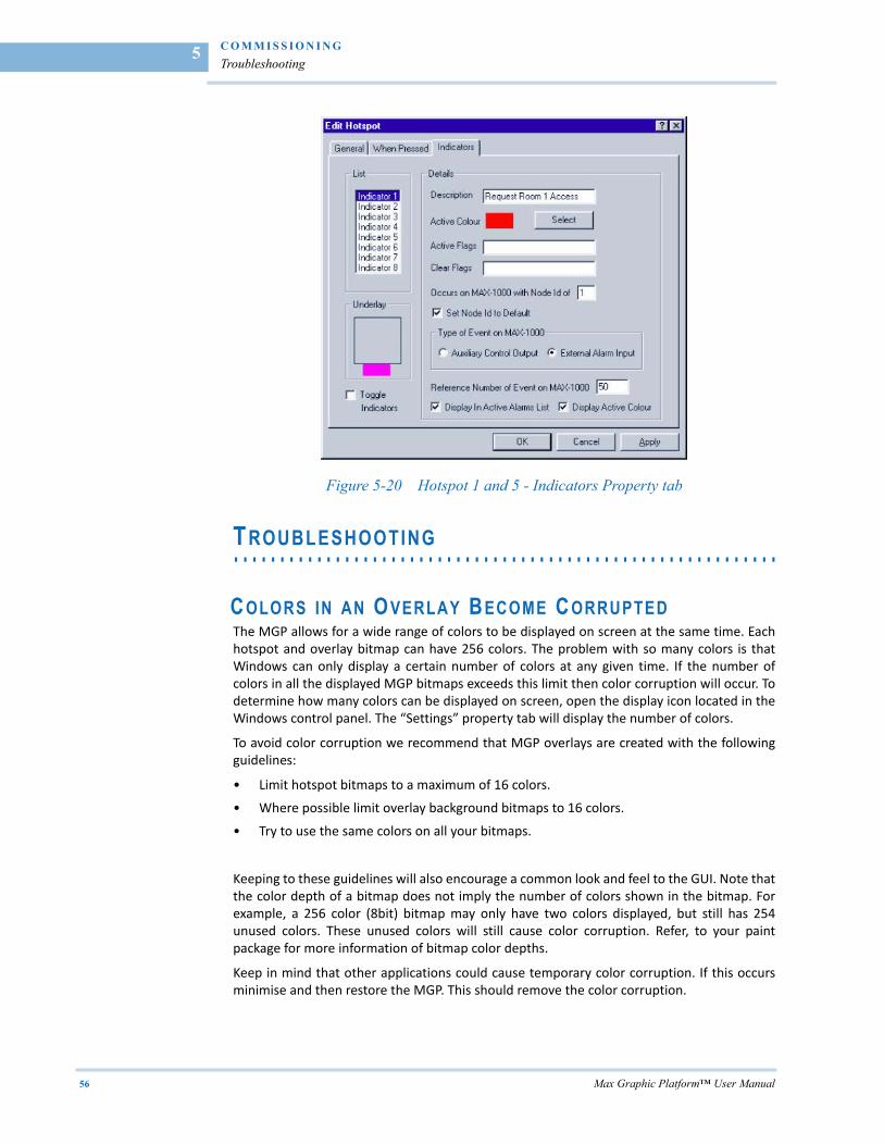
C O M M I S S I O N I N G
Troubleshooting
56 Max Graphic Platform™ User Manual
5
Figure 5-20 Hotspot 1 and 5 - Indicators Property tab
. . . . . . . . . . . . . . . . . . . . . . . . . . . . . . . . . . . . . . . . . . . . . . . . . . . . . . . . . . .TROUBLESHOOTING
COLORS IN AN OVERLAY BECOME C ORRUPTED The MGP allows for a wide range of colors to be displayed on screen at the same time. Eachhotspot and overlay bitmap can have 256 colors. The problem with so many colors is thatWindows can only display a certain number of colors at any given time. If the number ofcolors in all the displayed MGP bitmaps exceeds this limit then color corruption will occur. Todetermine how many colors can be displayed on screen, open the display icon located in theWindows control panel. The “Settings” property tab will display the number of colors.
To avoid color corruption we recommend that MGP overlays are created with the followingguidelines:
• Limit hotspot bitmaps to a maximum of 16 colors.
• Where possible limit overlay background bitmaps to 16 colors.
• Try to use the same colors on all your bitmaps.
Keeping to these guidelines will also encourage a common look and feel to the GUI. Note thatthe color depth of a bitmap does not imply the number of colors shown in the bitmap. Forexample, a 256 color (8bit) bitmap may only have two colors displayed, but still has 254unused colors. These unused colors will still cause color corruption. Refer, to your paintpackage for more information of bitmap color depths.
Keep in mind that other applications could cause temporary color corruption. If this occursminimise and then restore the MGP. This should remove the color corruption.
. .
. .
.
C O M M I S S I O N I N G
Troubleshooting
Max Graphic Platform™ User Manual 57
BITMAPS DO NOT IMPORT C ORRECTLY Only bitmaps with a color depth of up to and including 256 colors can be used on the MGP.Other bitmaps will not display. Also note that some paint packages have a bitmap formatthat is not compatible with the MGP™, including Microsoft® Paintbrush and Corel Draw v3.0.Maxpro has used a number of paint packages, which work well with the MGP. These includeAldus Photostyler v2.0 and Jasc Paint Shop Pro v4. They are not the only packages that willwork with the MGP™, but they are ones that we know to work well.
If you do have problems with a packages bitmap save format try the following technique.Save the image as another format. Load that image into another paint package. Use thispackage to save the image as a bitmap. This method works well with CAD packages whosebitmap formats does not work with the MGP. For example, to import AutoCAD images weuse a three step process. The image is saved as a HPGL file in AutoCAD. The image is thenloaded into Corel Draw v3.0 and saved as a GIF file. Finally, The image is loaded into PhotoPaint and saved as a bitmap file. Experimentation will often lead to the best results.
When importing bitmaps remember that if they do not display in the Import Bitmap dialogbox then they will not display on the overlay.

. .
. .
.
I N D E X
INDEX
AAdding Hotspots to an Overlay 43Alarms 14
CCommunicating between the MAXPRO™ VMS andthe MGP 39Communications 14Configuring the MAXPRO™ VMS 38Configuring the MGP 39Creating an Overlay 41
DDisplaying Video on the MGP 40
EEdit Overlays 18Editing Hotspot Graphics 43Events 6
FFile Menu 11
GGenerating Events from a Hotspot Press 50Graphical Interface 5
HHardware and Software Requirement 3Help menu 30Hot Spot Menu 29
MManage Bitmaps 17Manage User 27MGP Defaults 37MGP Installation 10Miscellaneous 16
OOverlays 34
PPicture Settings 29
RResponding to Events 55
SSettings Menu 13Standard Installation 33
TTouch Screen Interface 9
UUsers 33
VVideo Interface Card Installatio 9
WWindow Menu 12


© 2010 Honeywell International Inc. All rights reserved. No part of this publication may be reproduced by any means without written permission from Honeywell Video Systems. The information in this publication is believed to be accurate in all respects. However, Honeywell Video Systems cannot assume responsibility for any consequences resulting from the use thereof. The information contained herein is subject to change without notice. Revisions or new editions to this publication may be issued to incorporate such changes.
Document 800-xxxxx – Rev A – MO/YR
Honeywell Video Systems (Head Office)2700 Blankenbaker Pkwy, Suite 150Louisville, KY 40299, USAwww.honeywellvideo.com +1.800.796.2288
Honeywell Security Australia Pty Ltd.Unit 5, Riverside Centre, 24-28 River Road WestParramatta, NSW 2150, Australiawww.honeywellsecurity.com/au +61.2.8837.9300
Honeywell Security Asia Pacific33/F Tower A, City Center, 100 Zun Yi RoadShanghai 200051, Chinawww.asia.security.honeywell.com +86 21.2527.4568
Honeywell Security AsiaFlat A, 16/F, CDW Building, 388 Castle Peak RoadTsuen Wan, N.T., Hong Kongwww.asia.security.honeywell.com +852.2405.2323
Honeywell Security FranceParc Gutenberg, 8, Voie La Cardon91120, Palaiseau, Francewww.honeywell.com/security/fr +33.01.64.53.80.40
Honeywell Security Italia SpAVia Treviso 2 / 431020 San VendemianoTreviso, Italywww.honeywell.com/security/it +39.04.38.36.51
Honeywell Security EspañaMijancas 1. 3a PlantaP.Ind. Las Mercedes28022 Madrid, Spainwww.honeywell.com/security/es +34.902. 667.800
Honeywell Video Systems Northern EuropeNetwerk 1211446 WV Purmerend, The Netherlandswww.honeywell.com/security/nl +31.299.410.200
Honeywell Systems GroupAston Fields Road, Whitehouse Ind EstRuncorn, Cheshire, WA7 3DL, UKwww.honeywell.com/security/uk +44 (0)1928 756999
Honeywell Security South AfricaUnit 6 Galaxy Park, 17 Galaxy AvenueLinbro Park, P.O. Box 599042100 Kengray, Johannesburg, South Africawww.honeywell.co.za +27.11.574.2500
Honeywell Security DeutschlandJohannes-Mauthe-Straße 14D-72458 Albstadt, Germanywww.security.honeywell.com/de +49.74 31.8 01.0
Honeywell Security PolandChmielewskiego 22a, 70-028Szczecin, Polskawww.ultrak.pl +48.91.485.40.60
Honeywell Security Czech RepublicHavránkova 33, BrnoDolní Heršpice, 619 00, Czech Republicwww.olympo.cz +420.543.558.111
Honeywell Security Slovakia RepublicVajnorská 142, 83104 BratislavaSlovakiawww.olympo.sk +421.2.444.54.660