Embed Size (px)
Citation preview
MonteringsanvisningUniguard Superflow UG-3-J och UG-3-O
Montering och placering.Uniguard skall placeras i flödesriktningen, enligt riktningspilen (se Uniguardfotens form eller ovansidan huset). Uniguard är lägesoberoende och kan monteras på valfri sida av kanalen men vid rektangulär kanal bör detektorn monteras på den kortaste sidan, för att samla in luft från så stor del av kanalen som möjligt.
Vi rekommenderar att Uniguard monteras på minst samma avstånd från kyl- och värmebatterier eller luftfuktare som luftflödesgivare. Den bör dessutom placeras så, att avståndet före närmaste störning i kanalen (t.ex. böj, filter eller spjäll) - i luftflödesriktningen räknat - är minst lika stort som 3 x kanalens diameter. Närmaste placering efter sådan störning bör vara 5 x kanaldiametern.
Exempel på installation med störkällor: - fläkt - spjäll - ljuddämpare - batteri - luftbehandlingsaggregat - kanalböj - avgrening - dimensionsförändring
Hydraulisk diameter
MIN 3xdh MIN 5xdh
UG-3 UG-3
FLÄKTFAN
MIN 5xdh
UG-3MIN
3xd
h
UG
-3
KANALBÖJDUCT BEND
UG-3
MIN 5xdh
UG-3MIN
3xd
h
UG
-3
MIN 3xdh
AVGRENINGDUCT BRANCHING
UG-3
UG-3
MIN 3xdh
MIN 5xdh
LUFTBEHANDLINGSAGGREGATAIR HANDLING UNIT
FRÅNLUFT / RETURN AIRTILLUFT / INLET AIR
Phone: +46 31-69 53 00 Fax: +46 31-29 32 91 [email protected] www.calectro.se
ENInstallation instructionUniguard Superflow UG-3-J and UG-3-O
SV
Mounting and positioning.The Uniguard should be installed with the air flow direction arrows (see the Uniguard foot’s shape or on the housing top) corresponding to the direction of the air flow in the duct. The Uniguard can be installed on any side of the duct. N.B. Rectangular ducts: In order to gain maximum air sampling coverage, install the Uniguard on the shortest side of a rectangular duct.
We recommend that the Uniguard is mounted at an equal distance from heating, cooling, or humidity devices, and similar to the siting for flow monitors.A distance of 3 times the duct diameter should be left before a damper, filter or change of the duct direction, and 5 times the diameter after these devices.
Hydraulic diameter
Example of installation at sources of interference: - fan - damper - silencer - battery - air handling unit- duct bend- duct branching- duct narrowing or expansion
5 dh 3 dh
Exempel på installationefter böjd trumdel.Example of location afterchange of duct direction.
Observera fotens form av en pil, vilken skall peka i luftströmmens riktning.Note the foot’s shape of an arrow, which shall be installed in the air flow direction.
Returluftintag.Air inlet.
Exempel på installationföre returluftintag.Example of location beforeair inlet.
Vid stora temperaturskillnader t.ex. utomhus eller på kallvindarmåste Uniguard isoleras från omgivande luft. Se punkt 9.Where large temperature variations occur, e.g. on outdoorlocations or in areas subject to external temperatures (roof,attics), the Uniguard should be insulated, see para 9.
dh
CIRKULÄR KANALCIRCULAR DUCT
REKTANGULÄR KANALRECTANGULAR DUCT
d = D
Ø D
h d = h2xHxBH+B H
B
© 2
015.
08.1
7 C
alec
tro A
B
HFE
300
1
5
2
3
4
Borra hål i kanalen:• Håltagning utan UG-beslag, ø 38 mm.• Håltagning med UG-beslag och/eller venturirör
med monterad fläkt, ø 51 mm (se punkt 10).
• Mät ventilationskanalens diameter.• Kapa eventuellt röret.• Röret bör täcka minst 90% av
kanalens diameter.OBS! Se även punkt 8.
• Sätt i ändpluggen.
• Träd på tätningen på röret.• För in röret i botten på Uniguard.• Lås fast röret med stoppskruven.
• Montera röret och detektorn på kanalen.• Fäst Uniguard på 3 punkter vid pilarnas
markering.
Uniguard är försedd med en indikator, en röd plasttunga, som – när detektorn är rätt installerad – svängs ut av luftströmmen.
OBS!Rör sig inte indikatorn alls bör man överväga en omplacering av detektorn, alternativt montera ett s.k. fläktrör*.
Vid montering av fläktrör används alltid ett monteringsbeslag.
Kapa EJ denna ände!Do NOT cut this end!
Ändplugg.End plugg.
Drill a hole in the duct:• Without UG-bracket, ø 38 mm.• With UG-bracket and/or venturi pipe with booster
fan, ø 51 mm (see para 10).
• Measure the diameter of the duct.• Shorten the pipe, if necessary. • The pipe should penetrate at least 90%
of the width of the duct. NOTE! See para 8.
• Insert the end plug.
• Mount the black gasket on the pipe.• Insert the pipe into the bottom of the
Uniguard.• Secure the pipe with the locking screw.
• Mount the pipe and the detector on the duct.• Secure the bottom of the Uniguard with
the 3 screws, positions marked.
NOTE - IMPORTANT!The air flow direction arrows (see the Uniguard foot’s shape or on the housing top) must have the same direction as the air flow in the duct.
Flödesindikator och fläktrör*.
Flödesindikator.Flow indicator.
The Uniguard is supplied with an indicator, a red plastic "tongue", which – when the detector is correctly installed – is bent outwards due to the airflow.
NOTE!If the indicator does not move, you should consider a new mounting positioning of the Uniguard or install a booster fan venturi pipe.
With installation of a booster fan venturi pipe a mounting bracket is always used.
OBS VIKTIGT!Riktningspilarna (se Uniguardfotens form eller ovansidan huset) skall ha samma riktning som luftflödet i kanalen.
Stoppskruv.Locking screw.
Tätning.Gasket.
Venturirör med hjälpfläkt.Venturi pipe with booster fan.
Flow indicator and booster fan pipe*.
* Fläktrör är ett standard venturirör med hjälpfläkt,vilken kräver separat 24 VAC/DC matning.
* A booster fan pipe is a standard venturi pipe including a booster fan, which needs separate 24 VAC/DC supply.
Elinstallation. 6• Öppna locket över kopplingshuset genom
att lyfta på snäpplåset.
• För in kabeln genom valfri Klikseal kabelgenomföring.Används annan typ av genomföring demonteras de förmonterade genom att först trycka igenom ena sidan och därefter den andra (1-2).
(1)
(2)
• Remove the cover by opening the snap locking.
• Enter the cable through one of the Klikseal glands.When using another type of cable gland dismount the ones already installed by first pressing one side through the hole and then the other one (1-2).
Electrical installation.Snäpplås.Snap locking.
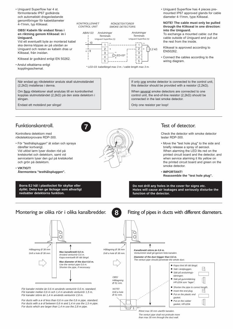
När endast en rökdetektor ansluts skall slutmotståndet (2,2kΩ) installeras i denna.
Om flera röktektorer skall anslutas till en kontrollenhet kopplas slutmotståndet (2,2kΩ) på den sista detektorn i slingan.
Endast ett motstånd per slinga!
Funktionskontroll. 7
AnslutningarTerminals
Uniguard Superflow (1)
* LED-03: kabellängd max 3 m. / cable length max 3 m.
AnslutningarTerminals
Uniguard Superflow (n)
LED-03*
KONTROLLENHETCONTROL UNIT
ABAV-S3
RÖKDETEKTORERSMOKE DETECTORS
Kontrollera detektorn med rökdetektorprovare RDP-300.
• För "testhålspluggen" åt sidan och spraya därefter kortvarigt.Vid utlöst larm lyser dioden röd på kretskortet och detektorn, samt vid servicelarm lyser den gul på kretskortet och grön på detektorn.
• VIKTIGT!Återmontera "testhålspluggen".
• Uniguard Superflow har 4 st. förmonterade IP67 godkända och automatiskt dragavlastande genomföringar för kabeldiameter 4-11mm, typ Klikseal.
OBS! Kabeln får endast föras i en riktning genom Klikseal: in i Uniguard.Vid ett eventuellt byte av monterad kabel ska denna klippas av på utsidan av Uniguard och resten av kabeln dras ur Klikseal, från insidan.
Klikseal är godkänd enligt EN 50262.
• Anslut elkablarna enligt kopplingsschemat.
• Uniguard Superflow has 4 pieces pre-mounted IP67 approved glands for cable diameter 4-11mm, type Klikseal.
NOTE! The cable must only be pulled through the Klikseal in one direction: into the Uniguard.To exchange a mounted cable: cut the cable outside of Uniguard and pull out the rest from the inside.
Klikseal is approved according to EN50262.
• Connect the cables according to the wiring diagram.
Check the detector with smoke detector tester RDP-300.
• Move the "test hole plug" to the side and briefly release a spray of aerosol.When alarming the LED lits red on the printed circuit board and the detector, and when service alarming it lits yellow on the printed circuit board and green on the smoke detector.
• IMPORTANT!Reassemble the "test hole plug".
Borra EJ hål i plastlocket för skyltar ellerdylikt. Detta kan ge läckage som allvarligtnedsätter detektorns funktion.
Do not drill any holes in the cover for signs etc.Holes will cause air leakages and seriously disturbe the function of the detector.
Test of detector.
Montering av olika rör i olika kanalbredder. 8
Drill a hole Ø 51 mm.
NOTE!
Håltagning Ø 51 mm.
OBS!
Kanalbredd större än 0,6 m. Venturiröret skall gå igenom hela kanalen.
Diameter of the duct bigger than 0,6 m. The venturi pipe should penetrate the whole duct.
Håltagning Ø 38 mmDrill a hole Ø 38 mm.
Håltagning Ø 38 mmDrill a hole Ø 38 mm.Max kanalbredd 0,6 m.
Använd venturirör 0,6 m.Kapa eventuellt till rätt längd.
Max diameter of the duct 0,6 m.Use the venturi pipe 0,6 m.Shorten the pipe, if necessary.
För kanaler mindre än 0,6 m används venturirör 0,6 m, standard.För kanaler mellan 0,6 m och 1,4 m används venturirör 1,5 m.För kanaler större än 1,4 m används venturirör 2,8 m.
For ducts with a ø of less than 0,6 m use the 0,6 m pipe, standard.For ducts with a ø of between 0,6 m and 1,4 m use the 1,5 m pipe.For ducts which are larger than 1,4 m use the 2,8 m pipe.
Kapa röret till rätt längd.Sätt i ändpluggen.Sätt på avslutnings-tätningen.Sätt på gummitätningHFU204 som "lager".
Shorten the pipe to correct length.Insert the end plug.Put on the plastic endgasket.Put on the rubbergasket, HFU204.
Röret max 30 mm utanför kanalen.The venturi pipe shall not protrude morethan max 30 mm through the duct wall.
Fitting of pipes in ducts with different diameters.
If only one smoke detector is connected to the control unit, this detector should be provided with a resistor (2,2kΩ).
When several smoke detectors are connected to one control unit, the end-of-line resistor (2,2kΩ) should be connected in the last smoke detector.
Only one resistor per loop!
Håltagning Ø 38 mm.Drill a hole Ø 38 mm.
Håltagning Ø 38 mm.Drill a hole Ø 38 mm.
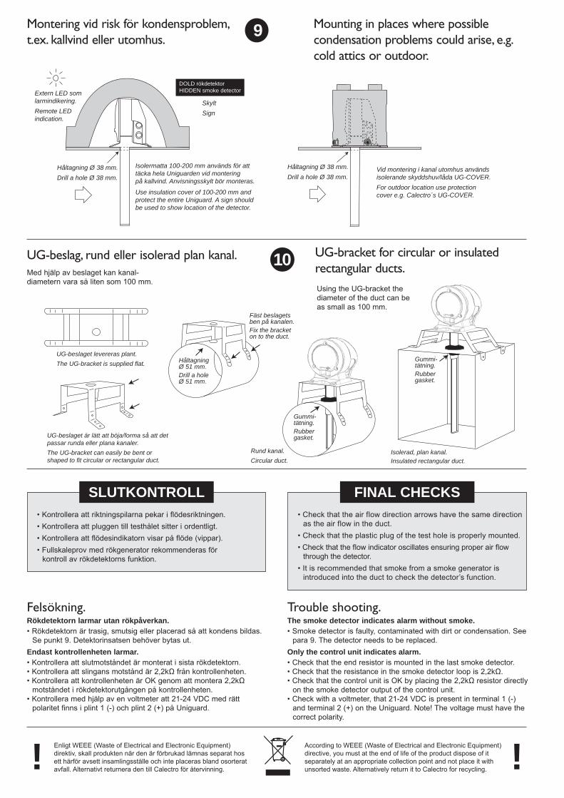
Vid montering i kanal utomhus användsisolerande skyddshuv/låda UG-COVER.For outdoor location use protectioncover e.g. Calectro´s UG-COVER.
Isolermatta 100-200 mm används för att täcka hela Uniguarden vid monteringpå kallvind. Anvisningsskylt bör monteras.
Use insulation cover of 100-200 mm andprotect the entire Uniguard. A sign shouldbe used to show location of the detector.
SkyltSign
Extern LED som larmindikering.Remote LED indication.
DOLD rökdetektorHIDDEN smoke detector
Montering vid risk för kondensproblem, t.ex. kallvind eller utomhus.
9
UG-beslaget levereras plant.The UG-bracket is supplied flat.
UG-beslaget är lätt att böja/forma så att detpassar runda eller plana kanaler.The UG-bracket can easily be bent or shaped to fit circular or rectangular duct.
HåltagningØ 51 mm.Drill a holeØ 51 mm.
Fäst beslagetsben på kanalen.Fix the bracketon to the duct.
Rund kanal.Circular duct.
Gummi-tätning.Rubbergasket.
Isolerad, plan kanal.Insulated rectangular duct.
Gummi-tätning.Rubbergasket.
UG-beslag, rund eller isolerad plan kanal. 10
SLUTKONTROLL• Kontrollera att riktningspilarna pekar i flödesriktningen.• Kontrollera att pluggen till testhålet sitter i ordentligt.• Kontrollera att flödesindikatorn visar på flöde (vippar).• Fullskaleprov med rökgenerator rekommenderas för
kontroll av rökdetektorns funktion.
Mounting in places where possible condensation problems could arise, e.g. cold attics or outdoor.
Med hjälp av beslaget kan kanal-diametern vara så liten som 100 mm.
UG-bracket for circular or insulated rectangular ducts.Using the UG-bracket the diameter of the duct can be as small as 100 mm.
FINAL CHECKS• Check that the air flow direction arrows have the same direction
as the air flow in the duct.• Check that the plastic plug of the test hole is properly mounted.• Check that the flow indicator oscillates ensuring proper air flow
through the detector.• It is recommended that smoke from a smoke generator is
introduced into the duct to check the detector’s function.
Felsökning.Rökdetektorn larmar utan rökpåverkan.• Rökdetektorn är trasig, smutsig eller placerad så att kondens bildas.
Se punkt 9. Detektorinsatsen behöver bytas ut.Endast kontrollenheten larmar.• Kontrollera att slutmotståndet är monterat i sista rökdetektorn.• Kontrollera att slingans motstånd är 2,2kΩ från kontrollenheten.• Kontrollera att kontrollenheten är OK genom att montera 2,2kΩ
motståndet i rökdetektorutgången på kontrollenheten.• Kontrollera med hjälp av en voltmeter att 21-24 VDC med rätt
polaritet finns i plint 1 (-) och plint 2 (+) på Uniguard.
Trouble shooting.The smoke detector indicates alarm without smoke.• Smoke detector is faulty, contaminated with dirt or condensation. See
para 9. The detector needs to be replaced.Only the control unit indicates alarm.• Check that the end resistor is mounted in the last smoke detector.• Check that the resistance in the smoke detector loop is 2,2kΩ.• Check that the control unit is OK by placing the 2,2kΩ resistor directly
on the smoke detector output of the control unit.• Check with a voltmeter, that 21-24 VDC is present in terminal 1 (-)
and terminal 2 (+) on the Uniguard. Note! The voltage must have the correct polarity.
Enligt WEEE (Waste of Electrical and Electronic Equipment) direktiv, skall produkten när den är förbrukad lämnas separat hos ett härför avsett insamlingsställe och inte placeras bland osorterat avfall. Alternativt returnera den till Calectro för återvinning.! According to WEEE (Waste of Electrical and Electronic Equipment)
directive, you must at the end of life of the product dispose of it separately at an appropriate collection point and not place it with unsorted waste. Alternatively return it to Calectro for recycling. !