Embed Size (px)
Citation preview
Morphology of nematic and smectic vesiclesXiangjun Xing (邢向军)a,1, Homin Shinb,2, Mark J. Bowickc,1, Zhenwei Yaoc, Lin Jiad, and Min-Hui Lid
aInstitute of Natural Sciences and Department of Physics, Shanghai Jiao Tong University, Shanghai 200240, China; bDepartment of Polymer Science andEngineering, University of Massachusetts, Amherst, MA 01003; cPhysics Department, Syracuse University, Syracuse, NY 13244; and dInstitut Curie, CentreNational de la Recherche Scientifique, Université Pierre et Marie Curie, UMR168, Laboratoire Physico-Chimie Curie, 26 rue d’Ulm, 75248 Paris CEDEX 05,France
Edited by* Paul M. Chaikin, New York University, New York, NY, and approved February 3, 2012 (received for review September 23, 2011)
Recent experiments on vesicles formed from block copolymerswith liquid-crystalline side chains reveal a rich variety of vesiclemorphologies. The additional internal order (“structure”) devel-oped by these self-assembled block copolymer vesicles can leadto significantly deformed vesicles as a result of the delicate inter-play between two-dimensional ordering and vesicle shape. Theinevitable topological defects in structured vesicles of sphericaltopology also play an essential role in controlling the final vesiclemorphology. Here we develop a minimal theoretical model for themorphology of the membrane structure with internal nematic/smectic order. Using both analytic and numerical approaches, weshow that the possible low free energy morphologies includenano-size cylindrical micelles (nano-fibers), faceted tetrahedralvesicles, and ellipsoidal vesicles, as well as cylindrical vesicles. Thetetrahedral vesicle is a particularly fascinating example of a facetedliquid-crystallinemembrane. Faceted liquid vesiclesmay lead to thedesign of supramolecular structures with tetrahedral symmetryand new classes of nano-carriers.
amphiphilic block copolymers ∣ bending energy ∣ Frank free energy ∣ liquidcrystalline polymers ∣ self-assembled bilayer
Amphiphilic block copolymers in water, like natural phospho-lipids, can self-assemble into various monolayer or bilayer
structures, such as micelles and vesicles (1, 2). In particular, rod-coil block copolymers, with a flexible hydrophilic chain and oneor more rod-like hydrophobic blocks, exhibit a rich morphologyof structures, and therefore have significant potential to advancefundamental science and drive technological innovations (3–12).Among these rod-coil block copolymers, we are especially inter-ested in liquid crystalline (LC) block copolymers in which the hy-drophobic block is a nematic or smectic liquid crystal polymer(13–20). The in-plane LC order that results from molecular pairinteractions in these systems, and the associated defect structure,play very important roles in determining the preferred intermedi-ate and final shapes of vesicles. The tailor-design of both materialproperties and vesicle morphology by controlling the molecularstructures of the block polymers is state-of-the-art research in thefields of polymer science, materials science, and chemical engi-neering.
Some of the structures formed by these LC side-chain blockcopolymers in aqueous solution are rather counterintuitive, suchas faceted vesicles, nanotubes and compact vesicles with tiny in-ner space (15, 20). In all these structures, the in-plane smecticorder is clearly visible under Cryo-TEM. In this article we developa theoretical explanation of the geometric structures of vesicleswith in-plane nematic or smectic order. We present a simple mod-el free energy as a functional of both the membrane geometry andthe in-plane nematic order. Using both analytic and numericalmethods, we then analyze the low free energy morphologies invarious parameter regimes.
Results and DiscussionsFocusing on their overall shape we first perform a mean-fieldanalysis of the model free energy of a self-assembled monolayeras a functional of their shape and nematic order parameters (21,22):
Hm ¼ 1
2
Z ffiffiffig
pd2x½Kð ~D n̂Þ2 þ κðH −H0Þ2� [1]
Here K is the Frank constant in the one-constant approximation,while ~D denotes the covariant derivative.H is the mean curvatureand H0 is the spontaneous curvature, which is determined by theasymmetry in the sizes of the hydrophobic and the hydrophilicparts of the LC block copolymers. We shall choose the normalvector of the monolayer to point from the hydrophobic side tothe hydrophilic side. ThereforeH > 0means that the hydrophilicside is bending outwards.
All three parameters K, κ, H0 depend on the chemical struc-tures of the block copolymers as well as their interaction with thesolvent in a complicated way. Furthermore, strictly speaking, anematic membrane is locally anisotropic. Therefore its Frank freeenergy is characterized by two constants: one for splay (K1) andone for bend (K3). Likewise, the bending energy as well as thespontaneous curvature should also be generically anisotropic,characterized by three bending constants and three spontaneouscurvature components. Such a model is characterized by eight in-dependent parameters and is extremely complicated to analyze.For the sake of simplicity, we shall focus on the greatly simplifiedtoy model Eq. 1, which captures the essential physics of nematicvesicles, which is the competition between the extrinsic bendingenergy and the two-dimensional Frank free energy.
A more important, conceptual issue is the following: In whatsense can the vesicle morphology be understood in terms ofminimization of elastic free energy Eq. 1? As is well known, theformation of vesicles is a complicated nonequilibrium process.Whether a certain property of a vesicle is distributed accordingto Gibbs-Boltzmann depends on the relevant experimental timescale, and on the time scale at which the given property equili-brates. At the stage of vesicle formation, individual molecules onthe membrane can diffuse quite efficiently. Motion of liquid crys-talline defects, however, requires coherent movement of all poly-mers on the vesicle, and is usually very slow. Hence we expect thatthe vesicle morphology achieves a local thermal equilibrium,where the shape and LC order minimizes the elastic free energyEq. 1 (with appropriate parameters corresponding to the physicalconditions under which the self-assembly takes place), subject toglobal constraints of given vesicle topology and LC defects dis-tribution. We shall then enumerate all possible vesicle topologiesand compare these free energy minima. It is interesting to notethat in recent experiments by Jia et al. (13), multiple vesicle topol-ogies were often observed using a given preparation method, sug-
Author contributions: X.X., M.J.B., L.J., and M.-H.L. designed research; X.X., H.S., M.J.B.,Z.Y., L.J., and M.-H.L. performed research; and X.X., H.S., and M.J.B. wrote the paper.
The authors declare no conflict of interest.
*This Direct Submission article had a prearranged editor.1To whom correspondence may be addressed. E-mail: [email protected] or [email protected].
2Present address: Department of Material Science and Engineering, University of Illinois,1304 West Green Street, Urbana, IL 61801.
This article contains supporting information online at www.pnas.org/lookup/suppl/doi:10.1073/pnas.1115684109/-/DCSupplemental.
5202–5206 ∣ PNAS ∣ April 3, 2012 ∣ vol. 109 ∣ no. 14 www.pnas.org/cgi/doi/10.1073/pnas.1115684109
gesting that kinetics of self-assembly also played an importantrole in the selection of vesicle morphology.
Smectic vesicles can also be viewed as nematic vesicles withbending constant much larger than splay constant. On a mem-brane with in-plane smectic order, therefore, the bending defor-mation of the nematic director field should vanish everywhere.Mathematically this is equivalent to n̂ · Dn̂ ¼ 0, that is, the ne-matic director locally follows the geodesics. This is always possi-ble, for an arbitrary but prescribed membrane shape, except atthe core of nematic disclinations. For these configurations, theFrank free energy becomes independent of the bending constant.Hence Eq. 1 is also a toy model for membranes with in-planesmectic order, with the understanding that K is the splay constantand the nematic director strictly follows the local geodesics.
Minimization of the Frank free energy in Eq. 1 requires thatthe covariant derivatives of the nematic director field vanisheverywhere on the surface. As is well known in differential geo-metry, this is possible only if the Gaussian curvature vanisheseverywhere; i.e. the surface is a developable surface. The familyof developable surfaces includes planes, cylinders, cones, and tan-gent developable surfaces*. On the other hand, minimization ofthe bending energy in Eq. 1 leads to a constant mean curvatureH0. It is clear that the only geometry minimizing both terms in thefree energy in Eq. 1 is a cylindrical monolayer with a given radius1∕H0. In the recent example of Jia et al. (13), for example, whereonly aqueous solvent is present at the final stage of assembly,monolayer cylinders with very small radius (nano-fibers) are ob-served. The inner space of the cylinders is completely filled by thehydrophobic parts of the polymers. In order to form monolayercylinders with larger radius, the inner space has to be filled bysolvents (or other polymers) that are friendly to LC blocks. Ifthere is only aqueous solvent, and if 1∕H0 is not small, monolayercylindrical structures with favorable spontaneous curvatures can-not pack space and therefore the system should form certainkinds of bilayer structures, where two monolayers with oppositeorientation stack together.
The free energy of a symmetric bilayer membrane can be ob-tained by adding up the free energies for two monolayers on bothsides of the bilayer:
Hm ¼Z ffiffiffi
gp
d2x½Kð ~D n̂Þ2 þ κH 2� [2]
We shall focus on the morphology of symmetric bilayers in theremainder of this article. Note that area differences betweenthe inner and outer layer can lead to nonvanishing spontaneouscurvature (23, 24). These effects will not qualitatively change ourconclusions.
Without considering the boundary effects, a flat bilayer withuniform nematic order clearly minimizes both terms in Eq. 2.The energy cost associated with the boundary, however, increaseswith the system size, and exceeds that associated with a closedvesicle with nonzero curvature, for sufficiently large systems(25). Closed vesicles therefore must form for sufficiently largebilayer membranes.
The morphology of a bilayer is controlled by the competitionbetween the extrinsic bending energy and the Frank free energy.We shall first limit the discussion to closed vesicles of sphericaltopology. Since the total Gaussian curvature is nonvanishing,the system is frustrated and the Frank free energy competes withthe bending energy. First consider the limiting case K ≪ κ. Thedominant contribution to the total energy is then the bending en-ergy: minimizing this leads to a round spherical shape. For a more
realistic model where the bending energy is not isotropic, how-ever, the shape will reflect the anisotropy of the bending moduli,leading to ellipsoidal shapes. The exact form of the shape as afunction of the bending moduli is rather difficult to calculate,however, and will not be treated in this article. Ellipsoidal vesiclesare frequently observed in the experiments of Jia et al. (14), withthe smectic layers all perpendicular to the long axis of the ellip-soid. It can be inferred from this observation that the bendingrigidity is higher along the nematic director than perpendicularto the director.
Let us now consider the opposite regime where K ≫ κ. In thiscase, the system should first minimize the Frank free energy,which leads to developable surfaces with vanishing Gaussian cur-vature everywhere. This is clearly not possible due to Gauss’ The-orem Egregium, which states that the total integrated Gaussiancurvature of a surface with spherical topology is a topological in-variant and equal to 4π. There are faceted polyhedral surfaces,however, for which the Gaussian curvature vanishes everywherebut at a discrete number of (singular) vertices. These vertices arethe ideal locations for orientational defects of the LC order (mis-ery loves company) (26). The total defect strength on a closedsurface is also a topological invariant, according to the Gauss-Bonnet theorem. For nematic and smectic orders, this theoremdictates that on a sphere (or any other surface with the same to-pology), there are three possibilities for the structure of defects:(i) four disclinations each with strength þ1∕2; (ii) two defectseach with strength þ1; (iii) one strength þ1 defect and twostrengthþ1∕2 defects. Now one needs at least four points to spana nondegenerate polyhedron; a tetrahedron in the minimal case.We conclude that in the limiting case K ≫ κ, the ground statemorphology of a vesicle with spherical topology is a faceted tet-rahedron, with a strength 1∕2 disclination located at each of thefour corners. This structure is indeed observed in recent experi-ments (15, 20), as well as in our simulation, to be discussed indetail below. Note that the faceting observed here has a comple-tely different origin to the well-known buckling of elastic shellswhere buckling occurs above a critical size R ∼
ffiffiffiffiffiffiffiffiffiκ∕Y
p, with Y
the Young’s modulus. The free energy Eq. 2, on the other hand,is scale free—the ground states are determined solely by the di-mensionless ratio K∕κ.
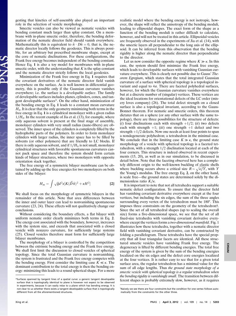
It is important to note that not all tetrahedra support a suitablenematic defect configuration. To ensure that the director fieldhas vanishing covariant derivative everywhere except at the fourvertices, but including the six edges, the sum of the three anglessurrounding every vertex of the tetrahedron must be 180°. Thisimposes three constraints on the geometry of the tetrahedron†.Since the set of all tetrahedral shapes (up to scaling the overallsize) forms a five-dimensional space, we see that the set of allfixed-size tetrahedra with vanishing covariant derivative every-where except the vertices forms a two-dimensional manifold. Fig. 1illustrates how these tetrahedra, together with a nematic directorfield with vanishing covariant derivative, can be constructed byfolding a parallelogram. These tetrahedra have the special prop-erty that all four triangular facets are identical. All these struc-tured smectic vesicles have vanishing Frank free energy. Thedegeneracy is lifted by different bending energies. The total freeenergy of the system is given by the sum of the bending energieslocalized on the six edges and the defect core energies localizedat the four vertices. It is rather easy to see that for a given totalsurface area, the regular tetrahedron has a minimal value for thesum of all edge lengths. Thus the ground state morphology of asmectic vesicle with spherical topology is a regular tetrahedron whenthe bending rigidity is vanishingly small. The transition between dif-ferent shapes is probably extremely slow, however, as it requires*Surfaces spanned by tangent lines of a spatial curve: a generic tangent developable
surface that is topologically identical to plane is however not expect to be observedin experiments, because it can easily relax to a plane which has bending energy. It isnot clear to us whether there exists a tangent developable surface that is topologicallydifferent from all the aforementioned structures.
†Naively we see there are four constraints but the condition for one vertex follows auto-matically from the constraints for the other three.
Xing et al. PNAS ∣ April 3, 2012 ∣ vol. 109 ∣ no. 14 ∣ 5203
PHYS
ICS
coherent motion of all four nematic disclinations together withthe overall smectic layer texture.
The edges and corners cannot be infinitely sharp in a realisticsystem. They are rounded by either the membrane thickness, thecore size of a nematic defect, or the small bending rigidity κ. Like-wise, the bending energy on the edges must be finite. In a realisticself-assembly process, the bending energy may also be partially
relieved by preferential aggregation of large polymers on theoutside and smaller polymers on the inside of the membrane nearthe ridges and corners. Faceted surface structures were studiedpreviously in large viral capsids (27, 28), which are formed bycrystalline packing of proteins. There the faceting is energeticallyfavorable because it reduces the in-plane strain energy of the crys-talline order formed by the constituent proteins. What we haveshown here is that a similar faceting can also be driven by theFrank free energy of LC order, despite their liquid nature.
Another candidate for a low free energy morphology is a longcylinder of double layers (nanotube), for which the Frank freeenergy also vanishes. The bending energy is approximately givenby
Hnanotube ¼ κA∕a2; [3]
where a is the radius of the cylinder. The total bending free en-ergy is therefore linear in the membrane area. The faceted tetra-hedron, on the other hand, has the total free energy
Htetrahedron ¼ 4κL∕b; [4]
where L is the length of ridges and b is the radius of curvature ofrounded out ridges. Since the area of a tetrahedron grows quad-ratically in L, it follows that the total bending energy for a tetra-hedron scales as the square root of the membrane area. Largefaceted tetrahedral vesicles thus have lower free energy than na-notubes. Both morphologies, however, have been observed ex-perimentally (14, 15, 20). Selection of vesicle morphology isalso affected by kinetics of self-assembly, as we discussed above.
In order to quantitatively investigate the ground state mor-phology of nematic vesicles, we develop a lattice nematic modelon a deformable surface with spherical topology and perform en-ergy minimization by the method of simulated annealing MonteCarlo (MC). Details of the discretized form of the free energy,whose continuum limit is given by Eq. 2, can be found in Ref. (29)and the Methods section.
The simulation results for nematic vesicles at various bendingrigidities show remarkable morphological transitions, as dis-
Fig. 1. Top: A tetrahedron compatible withþ1∕2 disclination on each vertexcan be constructed using a parallelogram, by folding along the dashed lines.A constant nematic director field in the unfold parallelogram is shown by thearray of parallel straight lines. After folding up, the angles with same colorcircle around the same vertex. Bottom: The tetrahedron obtained via folding.There is exactly one þ1∕2 disclination on each vertex of the tetrahedron.
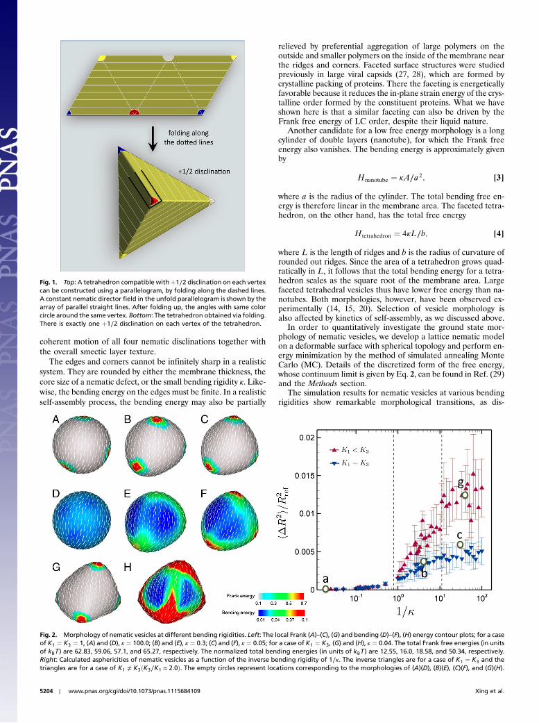
Fig. 2. Morphology of nematic vesicles at different bending rigidities. Left: The local Frank (A)–(C), (G) and bending (D)–(F), (H) energy contour plots; for a caseof K1 ¼ K3 ¼ 1, (A) and (D), κ ¼ 100.0; (B) and (E), κ ¼ 0.3; (C) and (F), κ ¼ 0.05; for a case of K1 ¼ K3, (G) and (H), κ ¼ 0.04. The total Frank free energies (in unitsof kBT ) are 62.83, 59.06, 57.1, and 65.27, respectively. The normalized total bending energies (in units of kBT ) are 12.55, 16.0, 18.58, and 50.34, respectively.Right: Calculated asphericities of nematic vesicles as a function of the inverse bending rigidity of 1∕κ. The inverse triangles are for a case of K1 ¼ K3 and thetriangles are for a case of K1 ≠ K3ðK3∕K1 ≈ 2.0Þ. The empty circles represent locations corresponding to the morphologies of (A)(D), (B)(E), (C)(F), and (G)(H).
5204 ∣ www.pnas.org/cgi/doi/10.1073/pnas.1115684109 Xing et al.
played in Fig. 2. For convenience we set K ¼ 1. This does notchange any essential physics since the vesicle morphology de-pends only on the dimensionless ratio κ∕K. As the bending rigid-ity κ decreases, the vesicles with an isotropic Frank elasticconstant undergo substantial shape deformation: (i) the almostspherical morphology is found to be stable at large κ (Fig. 2 Aand D); (ii) ridges connecting four defects develop as κ becomessmaller than 1 (Fig. 2 B and E); (iii) a tetrahedral vesicle forms ata vanishingly small κ ¼ 0.05 (Fig. 2 C and F). The faceting transi-tion occurs near κ ≃ 1 ‡. The stable morphologies are determinedby a delicate balance between the in-plane Frank energy and thebending energy as the surface deforms away from round. Indeed,as κ decreases from 100.0 to 0.05, the Frank free energy falls from62.83 to 57.1 at the expense of bending energy which increasesfrom 12.55 to 18.58. The Frank energy is localized near the fourdefects, which consequently induce deformation around the ver-tices. Our simulations are therefore entirely consistent with ourprediction that spherical vesicles are stable in the regime ofK ≪ κ, whereas the faceted tetrahedral vesicles become stablein the other extreme K ≫ κ.
We also explore the effect of anisotropy in the Frank elasticconstants by studying the regime in which splay dominates overbend. The smectic regime, as noted earlier, corresponds to thelimit K3 ≫ K1. In the current simulation, the anisotropy is esti-mated to beK3∕K1 ≃ 2.0 (see Supporting Information). Althoughthe shape transition trends are qualitatively similar for both theone-Frank constant and anisotropic cases, the anisotropy leads toa more dramatic shape transition, resulting in a considerablymore faceted tetrahedral vesicle at a very small κ ¼ 0.04, as dis-played in Figs. 2 G and H. In fact, the splay dominant nematictexture enhances the faceting more than the isotropic case does.This is clearly understood by considering two membranes whichpossess aþ1 disclination defect with pure splay and pure bendingnematic textures, respectively. The pure splay always decreasesthe Frank energy by buckling out-of plane, because it allowsthe defect to escape into the third dimension and thus better alignthe nematic directors. On the other hand, such out-of-plane de-formation of the pure bending does not alter the Frank energyand therefore, the faceting of pure bending membranes is not fa-vorable upon deformation. Note that we are restricting ourselveshere to the case of isotropic bending rigidity.
More prominent shape changes for vesicles with the anisotropicFrank elastic constants are clearly confirmed from a quantitativemeasurement of the asphericity (i.e., degree of deviation from thereference unit sphere geometry), which is defined as follows:
hΔR2iR2
ref¼ 1
N∑N
α¼1
ðRα −RrefÞ2R2
ref; [5]
where Rα is the radial distance of vertex α, Rref is the radius of thereference unit sphere, and N is the total number of vertices. Theasphericities are averaged over 10 simulation runs for each κ andplotted in Fig. 2 as a function of 1∕κ. The plot exhibits relativelylarge deviations from its average values, especially at low bendingrigidity. This is mainly attributable to the differences in the aspheri-city between the three possible ground state morphologies.Although faceted tetrahedral vesicles are expected to be theground state for large system sizes, we have observed in our simu-lation three different ground state morphologies, presumably dueto its finite system size: (i) an ellipsoidal vesicle with two closelybounded disclination pairs; (ii) a flattened (square cushion-shape)vesicle with four þ1∕2 disclinations located approximately in oneplane; and (iii) a tetrahedral vesicle with four well separatedþ1∕2defects (see Supporting Information). These three morphologies
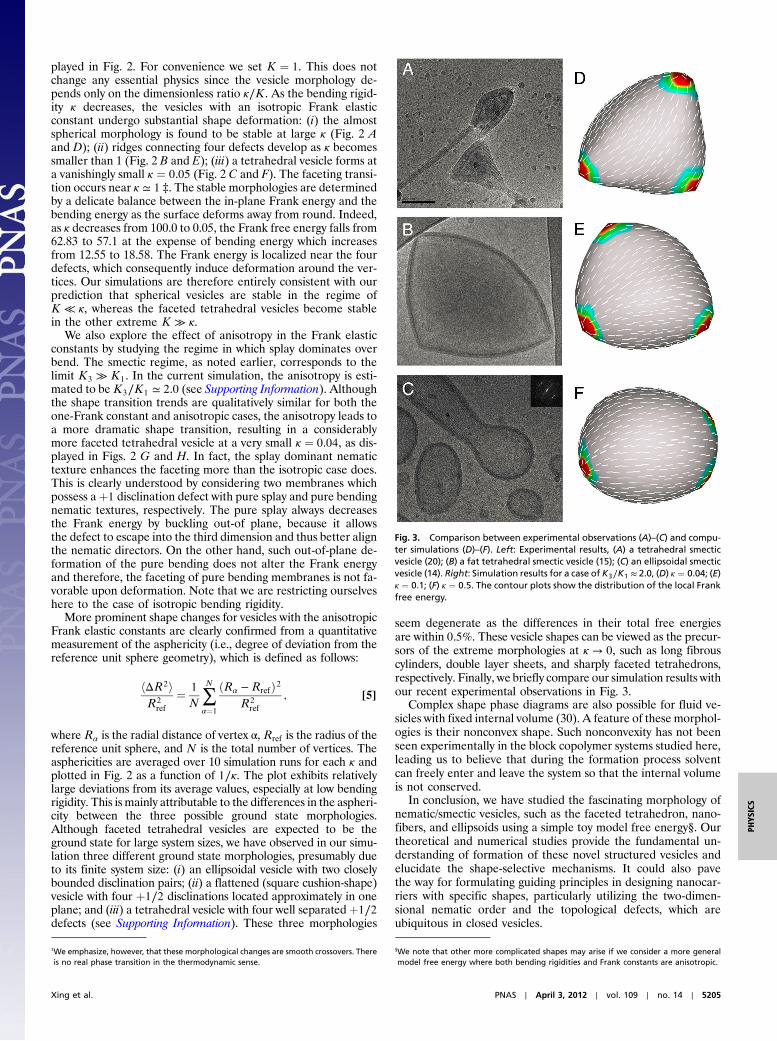
seem degenerate as the differences in their total free energiesare within 0.5%. These vesicle shapes can be viewed as the precur-sors of the extreme morphologies at κ → 0, such as long fibrouscylinders, double layer sheets, and sharply faceted tetrahedrons,respectively. Finally, we briefly compare our simulation results withour recent experimental observations in Fig. 3.
Complex shape phase diagrams are also possible for fluid ve-sicles with fixed internal volume (30). A feature of these morphol-ogies is their nonconvex shape. Such nonconvexity has not beenseen experimentally in the block copolymer systems studied here,leading us to believe that during the formation process solventcan freely enter and leave the system so that the internal volumeis not conserved.
In conclusion, we have studied the fascinating morphology ofnematic/smectic vesicles, such as the faceted tetrahedron, nano-fibers, and ellipsoids using a simple toy model free energy§. Ourtheoretical and numerical studies provide the fundamental un-derstanding of formation of these novel structured vesicles andelucidate the shape-selective mechanisms. It could also pavethe way for formulating guiding principles in designing nanocar-riers with specific shapes, particularly utilizing the two-dimen-sional nematic order and the topological defects, which areubiquitous in closed vesicles.
Fig. 3. Comparison between experimental observations (A)–(C) and compu-ter simulations (D)–(F). Left: Experimental results, (A) a tetrahedral smecticvesicle (20); (B) a fat tetrahedral smectic vesicle (15); (C) an ellipsoidal smecticvesicle (14). Right: Simulation results for a case of K3∕K1 ≈ 2.0, (D) κ ¼ 0.04; (E)κ ¼ 0.1; (F) κ ¼ 0.5. The contour plots show the distribution of the local Frankfree energy.
‡We emphasize, however, that these morphological changes are smooth crossovers. Thereis no real phase transition in the thermodynamic sense.
§We note that other more complicated shapes may arise if we consider a more generalmodel free energy where both bending rigidities and Frank constants are anisotropic.
Xing et al. PNAS ∣ April 3, 2012 ∣ vol. 109 ∣ no. 14 ∣ 5205
PHYS
ICS
MethodsTo implement a deformable lattice model with spherical topology, we firstintroduce a reference sphere and tessellate it with a triangular mesh alongwith 12 requisite 5-disclinations. Afterward a dual lattice of the triangularmesh is constructed, each dual site being the center of mass of each plaquetteformed by the original triangular lattice. The details of the lattice geometryare illustrated in the Supporting Information. Let m̂α to be the unit vectornormal to the plaquette α. A director n̂α and a projection operatorN̂α ¼ n̂αn̂α are defined on each dual site with a constraint that it must beperpendicular to the plaquette normal: N̂α · m̂α ¼ 0.
Let dαβ be the bond length connecting two neighboring dual sites α andβ, and Sαβ be the area spanned by the bond αβ. The discretized Frank freeenergy is then given by
FFrank ¼ K∑hαβi
Sαβd−2αβTr½ðN̂β − N̂αÞ2� [6]
The bond lengths dαβ and the areas Sαβ are introduced to ensure that thelattice model is a proper discretization of the continuum model Eq. 2. Theyinsure that, up to errors which scale with the plaquette area Sαβ, the latticefree energy is invariant under change of triangulation. The discrete repara-metrization invariance is necessary so that the free energy depends only onvesicle shape and not on the specific structure of the mesh. This is implemen-ted for each shape as the vertices are deformed.
The discretized bending energy is given by
Fbending ¼ κ∑α
SαTrK2α ; [7]
where Kα is the extrinsic curvature tensor at site α, whilst Sα is the area of theplaquette α. The curvature tensor Kα of each plaquette α can be calculatedfrom the following three equations:
e jjαβ ¼ 1
2~e⊥αβ · Kα · ~e⊥αβ e jjαγ ¼ 1
2~e⊥αγ · Kα · ~e⊥αγ
e jjαδ ¼1
2~e⊥αδ · Kα · ~e⊥αδ;
[8]
where ~eαβ is the vector pointing from vertex α to vertex β, and e jjαβ and e⊥
αβ areits components parallel and perpendicular to the plaquette normal m̂α.
In theMC simulations, the deformable surface consists of 300 vertices, cor-responding to 596 directors in all. The initial shape of the surface is a unitsphere and the initial director orientations are random. Each MC sweep con-sists of trial attempts to rotate each director and to move each vertex. Theacceptance or rejection of a MC trial is determined by the standard Metro-polis algorithm. All vertices are allowed to move along the radial directionwith the angular positions of the vertices fixed. In order to preserve the totalarea upon surface deformation, any vertex moves making a total areachange larger than 1% are rejected. Finally, once the surface is deformedby vertex moves, the orientations of directors are corrected by projectingthem onto the newly deformed plaquette before the new free energy is cal-culated.
Finally we remark that we have checked carefully that the location of ne-matic defects is not influenced by the inevitable lattice disclinations asso-ciated with spherical topology and present in our meshes as described above.
ACKNOWLEDGMENTS. X.X. thanks Shanghai Jiao Tong University for financialsupport. The work of H.S. was supported by the National Science Foundationthrough Grant DMR 09-55760. The work of M.J.B. and Z.Y. was supported bythe National Science Foundation through Grant DMR-0808812 and that ofZ.Y. by funds from Syracuse University. The work of L.J. and M.H.L. was sup-ported by the French Agence Nationale de la Recherche (ANR) grant ANR-08-BLANC-0209-01. We also acknowledge D. Lévy and A. Di Cicco (PICT-IBISA,Institut Curie) for EM imaging.
1. Discher DM, et al. (1999) Polymersomes: Tough vesicles made from diblock copolymers.Science 284:1143–1146.
2. Discher DE, Eisenber A (2002) Polymer vesicles. Science 297:967–973.3. Halperin A (1990) Rod-coil copolymers: their aggregation behaviour. Macromolecules
23:2724–2731.4. Jenekhe SA, Chen XL (1998) Self-assembled aggregates of rod-coil block copolymers
and their solubilization and encapsulation of fullerenes. Science 279:1903–1907.5. Jenekhe SA, Chen XL (1999) Self-assembly of ordered microporous materials from
rod-coil block copolymers. Science 283:372–375.6. Nowak A, et al. (2002) Rapidly recovering hydrogel scaffolds from self-assembling
diblock copolypeptide amphiphiles. Nature 417:424–428.7. Bellomo E, Wyrsta M, Pakstis L, Pochan D, Deming T (2004) Stimuli-responsive poly-
peptide vesicles by conformation-specific assembly. Nat Mater 3:244–248.8. Palmer LC, Stupp SI (2008) Molecular self-assembly into one-dimensional nanostruc-
tures. Acc Chem Res 41:1674–1684.9. Wang X, et al. (2007) Cylindrical block copolymermicelles and co-micelles of controlled
length and architecture. Science 317:644–647.10. He F, Gadt T, Manners I, Winnik MA (2011) Fluorescent barcode multiblock co-micelles
via the living self-assembly of di-and triblock copolymers with a crystalline core-form-ing metalloblock. J Am Chem Soc 133:9095–9103.
11. Yang J, Lévy D, DengW, Keller P, Li M-H (2005) Polymer vesicles formed by amphiphilicdiblock copolymers containing a thermotropic liquid crystalline polymer block. ChemCommun 34:4345–4347.
12. Mabrouk E, Cuvelier D, Brochard-Wyart F, Nassoy P, Li M-H (2009) Bursting of sensitivepolymersomes induced by curling. Proc Natl Acad Sci USA 106:7294–7298.
13. Pinol R, et al. (2007) Self-assembly of peg-b-liquid crystal polymer: The role of smecticorder in the formation of nanofibers. Macromolecules 40:5625–5627.
14. Jia L, et al. (2009) Smectic polymer vesicles. Soft Matter 5:3446–3451.15. Xu B, et al. (2009) Self-assembly of liquid crystal block copolymer peg-b-smectic poly-
mer in pure state and in dilute aqueous solution. Faraday Discussions 143:235–250.16. Boisse S, et al. (2009) Synthesis via RAFT of amphiphilic block copolymers with liquid-
crystalline hydrophobic block and their self-assembly in water. Macromolecules42:8688–8696.
17. del Barrio J, et al. (2010) Self-assembly of linear-dendritic diblock copolymers: Fromnanofibers to polymersomes. J Am Chem Soc 132:3762–3769.
18. Yang H, et al. (2010) Amphiphilic poly(ethylene oxide)-block-poly(butadiene-graft-li-quid crystal) copolymers: Synthesis and self-assembly in water. Macromolecules43:10442–10451.
19. Jia L, Albouy P-A, Di Cicco A, Cao A, Li M-H (2011) Self-assembly of amphiphilic liquid
crystal block copolymers containing a cholesteryl mesogen: Effects of block ratio andsolvent. Polymer 52:2565–2575.
20. Jia L, et al. (2011) Smectic polymer micellar aggregates with temperature-controlledmorphologies. Soft Matter 7:7395–7403.
21. MacKintosh FC, Lubensky TC (1991) Orientational order, topology, and vesicle shapes.Phys Rev Lett 67:1169–1172.
22. Frank JR, Kardar M (2008) Defects in nematic membranes can buckle into pseudo-spheres. Phys Rev E 77:041705.
23. Miao L, et al. (1994) Budding Transitions of fluid-bilayer vesicles: The effect of area-difference elasticity. Phys Rev E 49:5389–5407.
24. Svetina S, Zeks B (1989) Membrane bending energy and shape determination of phos-pholipid vesicles and red blodd cells. Eur Biophys J 17:101–111.
25. Helfrich W (1974) The size of bilayer vesicles generated by sonication. Phys Lett A50:115–116.
26. Lubensky TC, Prost J (1992) Orientational order and vesicle shape. J Phys II France2:371–382.
27. Lidmar J, Mirny L, Nelson DR (2003) Virus shapes and buckling transitions in sphericalshells. Phys Rev E 68:051910.
28. Nguyen TT, Bruinsma RF, Gelbart WM (2005) Elasticity theory and shape transitions ofviral shells. Phys Rev E 72:051923.
29. Shin H, Bowick MJ, Xing X (2008) Topological defects in spherical nematics. Phys RevLett 101:037802.
30. Sackmann E (1994) Membrane Bending Energy Concept of Vesicle-Shape and Cell-Shape and Shape-Transitions. FEBS Letters 346:3–16.
5206 ∣ www.pnas.org/cgi/doi/10.1073/pnas.1115684109 Xing et al.