Embed Size (px)
Citation preview
7/24/2019 MuMGE144EN
http://slidepdf.com/reader/full/mumge144en 1/18
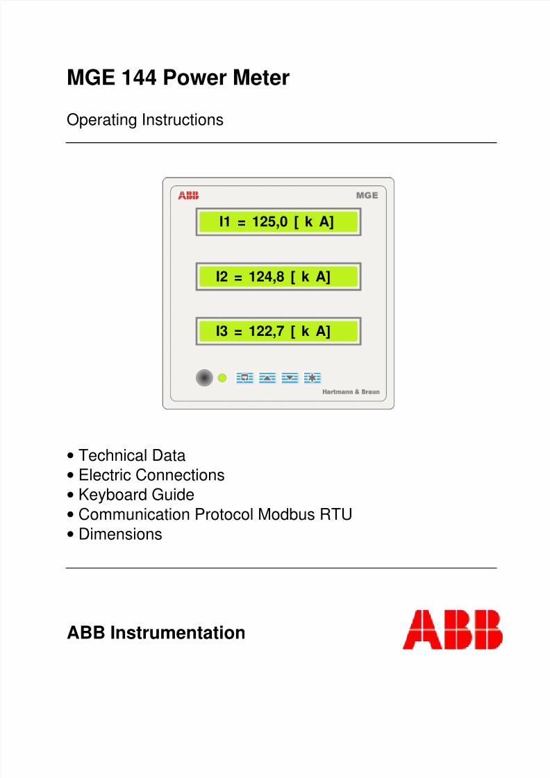
MGE 144 Power Meter
Operating Instructions
• Technical Data
• Electric Connections
• Keyboard Guide
• Communication Protocol Modbus RTU
• Dimensions
ABB Instrumentation
I1 = 125,0 [ k A]
I2 = 124,8 [ k A]
I3 = 122,7 [ k A]
7/24/2019 MuMGE144EN
http://slidepdf.com/reader/full/mumge144en 2/18
Index
1 Technical Data........................................................................................................................... 31.1 Input....................................................................................................................................... 31.2 Output .................................................................................................................................... 31.3 Bulk Storage........................................................................................................................... 31.4 Influence Magnitudes ............................................................................................................. 31.5 Additional Errors..................................................................................................................... 31.6 Electric Tests.......................................................................................................................... 31.7 Construction and mounting..................................................................................................... 31.8 Climatic conditions ................................................................................................................. 3
2 Electric Connections .................................................................................................................. 42.1 Auxiliary Power Supply........................................................................................................... 42.2 Voltage input signal................................................................................................................ 42.3 Current input signal ................................................................................................................ 4
2.4 Serial output RS 485............................................................................................................... 4
2.5 Serial output RS 232 .............................................................................................................. 42.6 Digital output .......................................................................................................................... 42.7 Analog output......................................................................................................................... 5
3 Keyboard Guide......................................................................................................................... 63.1 Menu Options......................................................................................................................... 63.2 Displays 1, 2, 3....................................................................................................................... 63.3 Configuration.......................................................................................................................... 6
3.3.1 Primary Current............................................................................................................... 73.3.2 Primary Voltage (Phase Voltage) .................................................................................... 73.3.3 Secondary Voltage (Phase Voltage)................................................................................ 73.3.4 Circuit Type..................................................................................................................... 73.3.5 Energy Range ................................................................................................................. 73.3.6 Pulse Output ................................................................................................................... 73.3.7 Baud Rate ....................................................................................................................... 7
3.3.8 MGE Address.................................................................................................................. 73.3.9 Reset............................................................................................................................... 73.3.10 Byte ............................................................................................................................. 7
4 Password................................................................................................................................... 85 Display of Maximum and Minimum Values................................................................................. 86 Exit ............................................................................................................................................ 87 Communication Protocol Modbus RTU .....................................................................................108 Special Functions .....................................................................................................................129 List of register ...........................................................................................................................1310 Configuration Registers of the Instrument .................................................................................1611 Bulk Storage.............................................................................................................................1712 Dimensional Drawing................................................................................................................18
This Operating Instruction is proper to MGE144 based on IBIS BE Software Version 00.60
7/24/2019 MuMGE144EN
http://slidepdf.com/reader/full/mumge144en 3/18
3
1 Technical Data1.1 Input Voltage Phase
63V127V220V
254V
Line110V220V380V
440V
Current 1A , 5A
Signal Limit U = 10…120%I = 10...120%
Power con-sumption
voltage input: ≤ 1mA.
current input: ≤ 0,2VA.
NominalFrequency
50; 60 Hz ±10% (other by consulting)
Overload Permanently: 1,5 U ; 2I short time:4U/1s;50I/1s maximum: 250A /1s
Auxiliarypower supply
85 … 265Vac90 … 300Vdcpower consumption ~ 6VA
1.2 OutputDigital output 5 outputs
4 outputs with alarm configurationfor any variable or pulse outputproportional to power and 1 faultsummary output. Pulse outputs (opencollector) 1...5000 pulses/h or duration:pulse width from 100 to 2000 ms(configurable)Maximum voltage 60Vcc.
Maximum current 20mA.
Analog output 4 analog outputs
0/4 …20mA RC ≤ 500 Ohm
0 …10V RC ≥100 kOhm
Interface Serial for interface RS232 or RS485Protocol Modbus RTU
1.3 Bulk Storage
Data are stored in a not volatile bulk storage, whichcan stay 48 hours of black out without loosing clocktime. The stored data are: month, day, hour, minute
and the preset measuring variables (memorizingcapacity of 12 variables at every 15 minutes, of thelast 40 days). The data are stored temporarilyoverwriting the last data. Any desired variable to bestored can be configured, as well as the measuringtime interval.Up to 20 variables can be configured and timeintervals from 5 up to 250 minutes.
1.4 Influence MagnitudesError limit 0,5%(normal),
0,25% (optional)Referenceconditions
Input: I = 10%...100% ;U = 10%...100%
Frequency: frated ±2%
Aux. powersupply:
Within range
Powerfactor:
cosine ϕ = 1 (activepower)
sine ϕ = 1 (reactive power)Ambienttemperature:
25°C ±2K
Heat up time 20 min. approx.
1.5 Additional ErrorsAdditional error above1,2I or 1,2U
≤ 0,2%
Linearity deviation ≤ 0,2% (included in error limit)
Temperature ≤ 0,2%/10 K; rated temperature25°C
Auxiliary power supply ≤ 0,05% within the tolerancerange admissible for the powersupply voltage
External magnetic fields ≤ 0,5% for field intensity of 0,4kA/m
1.6 Electric Tests
Test voltage 2,5kV/1 min - 60Hz between powersupply and remaining circuit0,5kV/1 min - 60Hz RS485, RS232,pulse output and analog output
1.7 Construction and mountingHousing Textured gray painted steel plateFixing By pairs of clamps Electricconnections
Voltage and current inputs terminals forring shaped cable shoesFor pulse and analog outputs, RS485 andauxiliary power supply terminals for pinshaped cable shoesFor RS232 output mini connector DIN6 onthe front of the instrument.
Weight ~ 1,5 kg
1.8 Climatic conditions
Operating temperature -20...+60°CFunctioning temperature -25...+70°CTransport and storagetemperature
-40...+80°C
7/24/2019 MuMGE144EN
http://slidepdf.com/reader/full/mumge144en 4/18
4
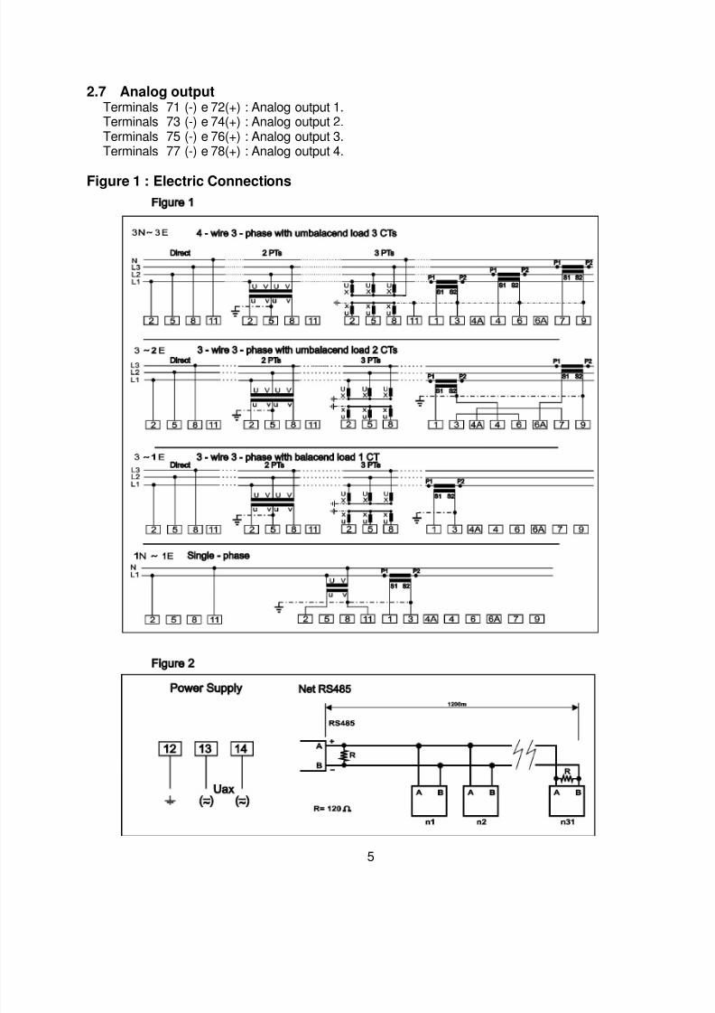
2 Electric Connections
Certify if voltages and currents to beconnected are compatible with theinstrument.
2.1 Auxiliary Power SupplyThe auxiliary power supply has to beconnected to the terminals 12, 13 e 14.Terminal 12 for ground.Terminals 13 and 14 for auxiliary powersupply.
2.2 Voltage input signalThe voltage signal input has to beconnected to the terminals 2, 5, 8, 11. Thevoltage input signal can be realized bymeans of a Potential Transformer ordirectly. The grounding of the secondaryPotential Transformer side is for protection;the grounded terminal is a suggestion andcan be modified. See figure 1
Terminal 2 phase L1Terminal 5 phase L2Terminal 8 phase L3Terminal 11 Neutral phase
2.3 Current input signalThe current signal input has to beconnected to the terminals 1, 3, 4, 6, 9. Thecurrent signal input can be realized bymeans of a Current Transformer or directly.The grounding of the secondary CurrentTransformer side is for protection; thegrounded terminal is a suggestion and canbe modified. See figure 1
Terminals 1 and 3 current of phase L1Terminals 4 and 6 current of phase L2Terminals 7 and 9 current of phase L3
2.4 Serial output RS 485The communication interface RS 485 can beconnected with a bus of up to 32 instruments,including the PC (Master). The connectionbetween the instruments can be realized bymeans of a pair of twisted wires or shieldedcable with a maximum length of maximum 1200m. The instruments are connected in parallelmode observing the signal polarity.
A termination resistor of 120 Ohms has to beconnected at the beginning and the end of theloop.
Terminal A (+)Terminal B (-)Terminal GND is for connection of cable
shield. When using a pair of twisted wires, thisterminal is not used. See figure 2.
Note: The serial output RS 485 will not functionwhen the cable of the local communication
RS 232 is connected to the instrument.
2.5 Serial output RS 232For this connection a special cable is available,which converts the TTL output signal in a signal
compatible with RS 232. The cable has at oneend a DIN6 mini connector which is plugged tothe instrument and a DB9 connector which isplugged to the PC; an adapter from DB9 toDB25 goes along with the cable, in case that thePC output is realized by a DB25.
Note. The RS 232 has priority over the RS 485output. That means, if the instrument is in
communication by means of the RS 485 and acable for local communication is beingconnected to the instrument, the instrumentpasses to the communication by means of the
RS 232.
2.6 Digital outputThe digital output is realized by means of opencollector.Terminals 32 (E), 33 (C) : Digital output 1
(when pulse output Active Energy Consumed)
Terminals 34 (E), 35 (C) : Digital output 2(when pulse output Active Energy Supplied)
Terminals 36 (E), 37 (C) : Digital output 3(when pulse output Reactive Energy Consumed)
Terminals 38 (E), 39 (C) : Digital output 4(when pulse output Reactive Energy Supplied)
Terminals 40 (E), 41 (C) : Fault summary output,
(When this output opens, it indicates fault)
Where : (E) emitter and (C) collector
7/24/2019 MuMGE144EN
http://slidepdf.com/reader/full/mumge144en 5/18
5
2.7 Analog outputTerminals 71 (-) e 72(+) : Analog output 1.Terminals 73 (-) e 74(+) : Analog output 2.Terminals 75 (-) e 76(+) : Analog output 3.Terminals 77 (-) e 78(+) : Analog output 4.
Figure 1 : Electric Connections
7/24/2019 MuMGE144EN
http://slidepdf.com/reader/full/mumge144en 6/18
6
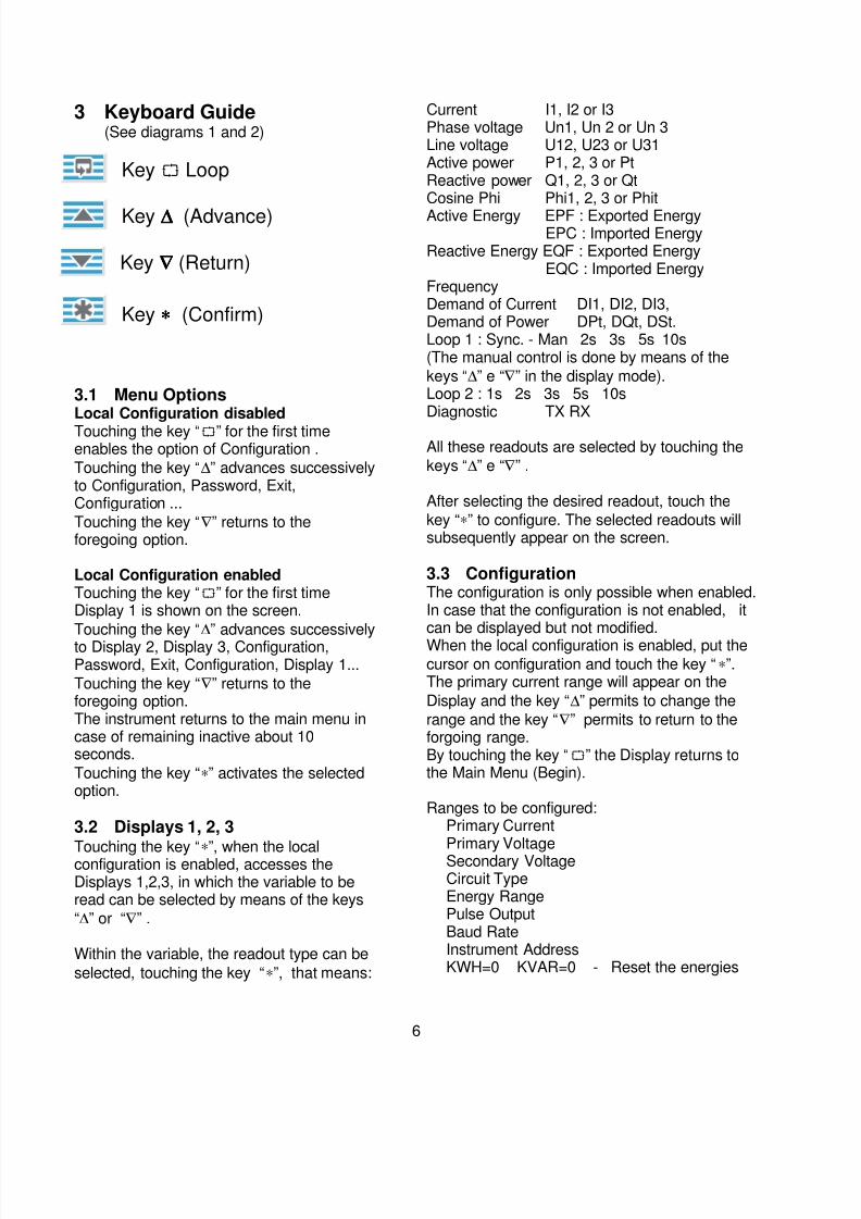
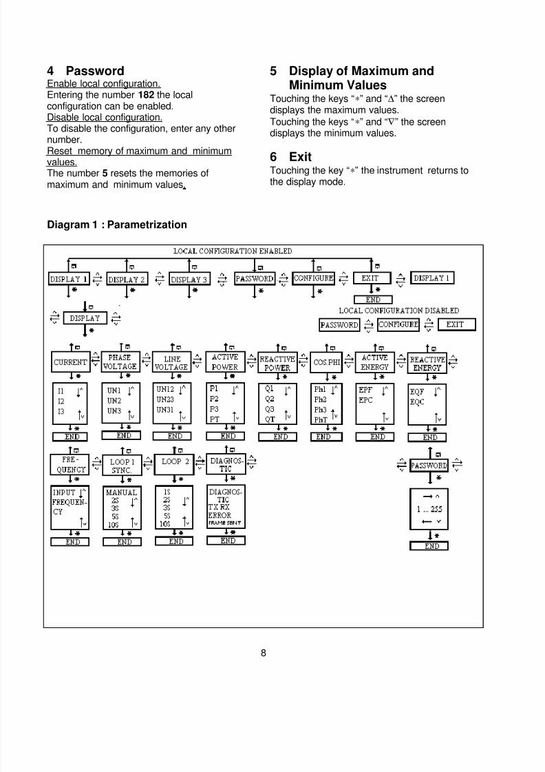
3 Keyboard Guide(See diagrams 1 and 2)
Key Loop
Key ∆∆∆∆ (Advance)
Key ∇∇∇∇ (Return)
Key ∗∗∗∗ (Confirm)
3.1 Menu OptionsLocal Configuration disabled
Touching the key “” for the first timeenables the option of Configuration .
Touching the key “∆” advances successivelyto Configuration, Password, Exit,Configuration ...
Touching the key “∇” returns to theforegoing option.
Local Configuration enabledTouching the key “” for the first timeDisplay 1 is shown on the screen.
Touching the key “∆” advances successivelyto Display 2, Display 3, Configuration,Password, Exit, Configuration, Display 1...
Touching the key “∇” returns to theforegoing option.The instrument returns to the main menu incase of remaining inactive about 10seconds.
Touching the key “∗” activates the selectedoption.
3.2 Displays 1, 2, 3
Touching the key “∗”, when the localconfiguration is enabled, accesses theDisplays 1,2,3, in which the variable to beread can be selected by means of the keys
“∆” or “∇” .
Within the variable, the readout type can be
selected, touching the key “∗”, that means:
Current I1, I2 or I3Phase voltage Un1, Un 2 or Un 3Line voltage U12, U23 or U31Active power P1, 2, 3 or PtReactive power Q1, 2, 3 or QtCosine Phi Phi1, 2, 3 or Phit
Active Energy EPF : Exported EnergyEPC : Imported Energy
Reactive Energy EQF : Exported EnergyEQC : Imported Energy
FrequencyDemand of Current DI1, DI2, DI3,Demand of Power DPt, DQt, DSt.Loop 1 : Sync. - Man 2s 3s 5s 10s(The manual control is done by means of the
keys “∆” e “∇” in the display mode).Loop 2 : 1s 2s 3s 5s 10sDiagnostic TX RX
All these readouts are selected by touching the
keys “∆” e “∇” .
After selecting the desired readout, touch the
key “∗” to configure. The selected readouts willsubsequently appear on the screen.
3.3 ConfigurationThe configuration is only possible when enabled.In case that the configuration is not enabled, itcan be displayed but not modified.
When the local configuration is enabled, put thecursor on configuration and touch the key “∗”.The primary current range will appear on the
Display and the key “∆” permits to change the
range and the key “∇” permits to return to theforgoing range.By touching the key “” the Display returns tothe Main Menu (Begin).
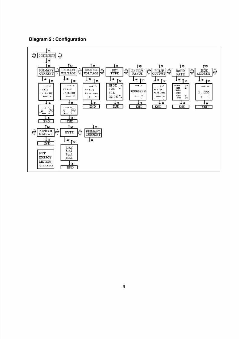
Ranges to be configured:Primary CurrentPrimary VoltageSecondary VoltageCircuit TypeEnergy RangePulse OutputBaud RateInstrument AddressKWH=0 KVAR=0 - Reset the energies

7/24/2019 MuMGE144EN
http://slidepdf.com/reader/full/mumge144en 7/18
7
3.3.1 Primary CurrentWhen the local configuration is enabled,
touch the key “∗” and adjust the currentwith the key:
“∆” from 0 to 9 + . (Point)
“∇” from 10 to 9999
Touch the key “∗” and adjust the unity withthe key:
“∆” kA or A
“∇” to finalize
3.3.2 Primary Voltage (PhaseVoltage)
When the local configuration is enabled,
touch the key “∗” and adjust the voltagewith the key:
“∆” from 0 to 9 + . (Point)
“∇” from 10 to 9999
Touch the key “∗” and adjust the unity withthe key:
“∆” kV or V
“∇” to finalize
3.3.3 Secondary Voltage (PhaseVoltage)
When the local configuration is enabled,
touch the key “∗” and adjust the voltagewith the key:
“∆” from 0 to 9 + . (Point)“∇” from 10 to 9999
“∗” to finalize
3.3.4 Circuit TypeWhen the local configuration is enabled,
touch the key “∗” and select the desiredcircuit type:
3N~ 3E3 ~2E3 ~1E1N~1E.
With the keys “∆” or “∇” circuit type selection ispossible. After selection of the circuit type touch
the key “∗” to finalize.
3.3.5 Energy RangeWhen the local configuration is enabled, touch
the key “∗” and select the energy rangebetween
999.999 kWh to 9999.99 GWh, using the keys “∆” ou
“∇”. After selection of the energy range touch the key
“∗” to finalize.
3.3.6 Pulse OutputWhen the local configuration is enabled, touch the
key “∗” and select the pulse rate with the key:“∆” from 0 to 9 + . (Point)
“∇” from 10 to 9999“∗” to finalize.
3.3.7 Baud RateWhen the local configuration is enabled, touch the
key “∗” and select the Baud Rate with the keys “∆” ou
“∇”:19200, 9600, 4800, 2400, 1200 or 600.
Touch the key “∗” to finalize.
3.3.8 MGE AddressWhen the local configuration is enabled, touch the
key “∗” and select the address of the instrument withthe key:
“∆” from 0 to 9 + . (Point)
“∇” from 10 to 255“∗” to finalize.
3.3.9 ResetkWh=0 kvarh=0Touch the key “∗” to return to zero
Touch the key “∗”to finalize.
3.3.10 ByteByte Type used for the bus communication. When the local configuration is enabled, touch
the key “∗” and select the desired Byte Type:8,n,2 : Without parity 2 Stop Bits8,e,1: Even Parity 1 Stop Bit8,o,1: Odd Parity 1 Stop Bit8,n,1: Without parity 1 Stop Bit
With the keys “∆” or “∇” the byte type can be
selected. After selection of the byte type touch thekey “∗” to finalize.
7/24/2019 MuMGE144EN
http://slidepdf.com/reader/full/mumge144en 8/18
8
4 PasswordEnable local configuration.Entering the number 182 the localconfiguration can be enabled.Disable local configuration.To disable the configuration, enter any othernumber.Reset memory of maximum and minimumvalues.The number 5 resets the memories ofmaximum and minimum values.
5 Display of Maximum andMinimum Values
Touching the keys “∗” and “∆” the screendisplays the maximum values.
Touching the keys “∗” and “∇” the screen
displays the minimum values.
6 ExitTouching the key “∗” the instrument returns tothe display mode.
Diagram 1 : Parametrization
7/24/2019 MuMGE144EN
http://slidepdf.com/reader/full/mumge144en 9/18
9
Diagram 2 : Configuration
7/24/2019 MuMGE144EN
http://slidepdf.com/reader/full/mumge144en 10/18
10
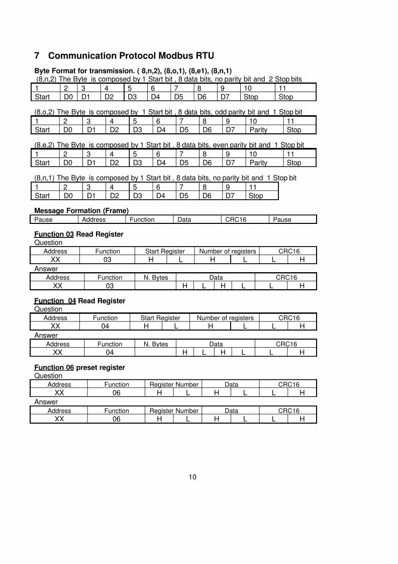
7 Communication Protocol Modbus RTU
Byte Format for transmission. ( 8,n,2), (8,o,1), (8,e1), (8,n,1)(8,n,2) The Byte is composed by 1 Start bit , 8 data bits, no parity bit and 2 Stop bits
1 2 3 4 5 6 7 8 9 10 11
Start D0 D1 D2 D3 D4 D5 D6 D7 Stop Stop
(8,o,2) The Byte is composed by 1 Start bit , 8 data bits, odd parity bit and 1 Stop bit
1 2 3 4 5 6 7 8 9 10 11Start D0 D1 D2 D3 D4 D5 D6 D7 Parity Stop
(8,e,2) The Byte is composed by 1 Start bit , 8 data bits, even parity bit and 1 Stop bit
1 2 3 4 5 6 7 8 9 10 11Start D0 D1 D2 D3 D4 D5 D6 D7 Parity Stop
(8,n,1) The Byte is composed by 1 Start bit , 8 data bits, no parity bit and 1 Stop bit
1 2 3 4 5 6 7 8 9 11
Start D0 D1 D2 D3 D4 D5 D6 D7 Stop
Message Formation (Frame)
Pause Address Function Data CRC16 Pause
Function 03 Read RegisterQuestion
Address Function Start Register Number of registers CRC16
XX 03 H L H L L H
AnswerAddress Function N. Bytes Data CRC16
XX 03 H L H L L H
Function 04 Read RegisterQuestion
Address Function Start Register Number of registers CRC16
XX 04 H L H L L H
AnswerAddress Function N. Bytes Data CRC16
XX 04 H L H L L H
Function 06 preset registerQuestion
Address Function Register Number Data CRC16
XX 06 H L H L L HAnswer
Address Function Register Number Data CRC16
XX 06 H L H L L H
7/24/2019 MuMGE144EN
http://slidepdf.com/reader/full/mumge144en 11/18
11
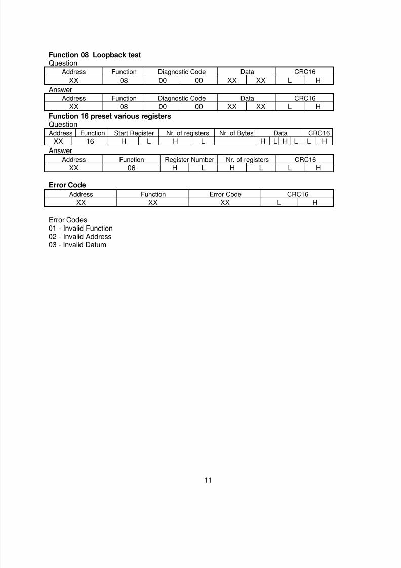
Function 08 Loopback testQuestion
Address Function Diagnostic Code Data CRC16
XX 08 00 00 XX XX L H
Answer
Address Function Diagnostic Code Data CRC16XX 08 00 00 XX XX L H
Function 16 preset various registersQuestionAddress Function Start Register Nr. of registers Nr. of Bytes Data CRC16
XX 16 H L H L H L H L L H
AnswerAddress Function Register Number Nr. of registers CRC16
XX 06 H L H L L H
Error Code
Address Function Error Code CRC16
XX XX XX L H
Error Codes01 - Invalid Function02 - Invalid Address03 - Invalid Datum
7/24/2019 MuMGE144EN
http://slidepdf.com/reader/full/mumge144en 12/18
12
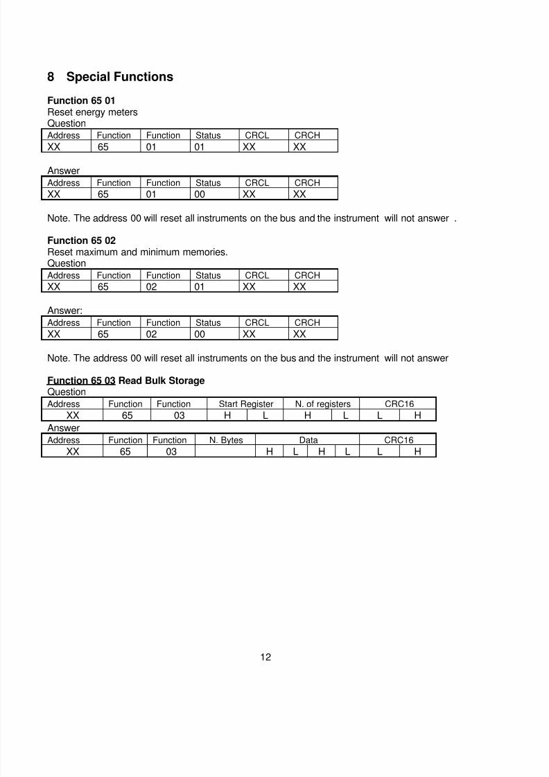
8 Special Functions
Function 65 01Reset energy metersQuestion
Address Function Function Status CRCL CRCHXX 65 01 01 XX XX
AnswerAddress Function Function Status CRCL CRCH
XX 65 01 00 XX XX
Note. The address 00 will reset all instruments on the bus and the instrument will not answer .
Function 65 02Reset maximum and minimum memories.Question
Address Function Function Status CRCL CRCH
XX 65 02 01 XX XX
Answer:Address Function Function Status CRCL CRCH
XX 65 02 00 XX XX
Note. The address 00 will reset all instruments on the bus and the instrument will not answer
Function 65 03 Read Bulk StorageQuestion
Address Function Function Start Register N. of registers CRC16XX 65 03 H L H L L H
AnswerAddress Function Function N. Bytes Data CRC16
XX 65 03 H L H L L H
7/24/2019 MuMGE144EN
http://slidepdf.com/reader/full/mumge144en 13/18
13
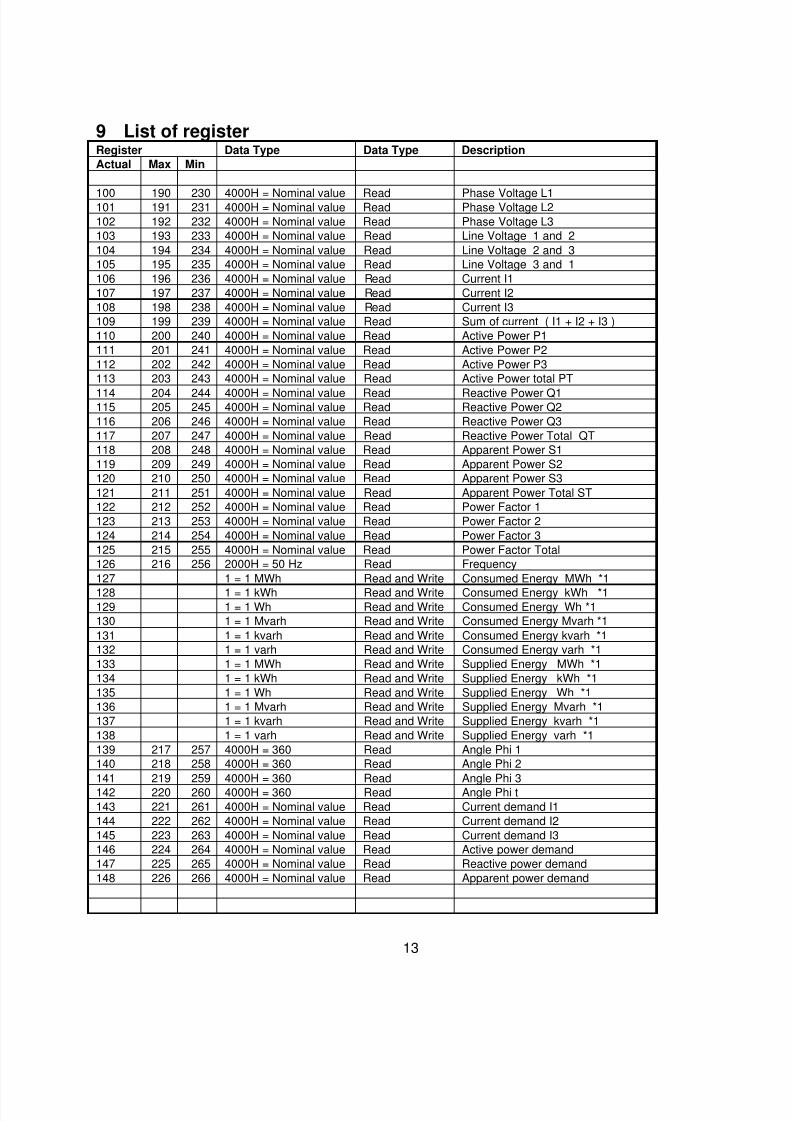
9 List of registerRegister Data Type Data Type Description
Actual Max Min
100 190 230 4000H = Nominal value Read Phase Voltage L1101 191 231 4000H = Nominal value Read Phase Voltage L2
102 192 232 4000H = Nominal value Read Phase Voltage L3
103 193 233 4000H = Nominal value Read Line Voltage 1 and 2
104 194 234 4000H = Nominal value Read Line Voltage 2 and 3
105 195 235 4000H = Nominal value Read Line Voltage 3 and 1
106 196 236 4000H = Nominal value Read Current I1
107 197 237 4000H = Nominal value Read Current I2
108 198 238 4000H = Nominal value Read Current I3
109 199 239 4000H = Nominal value Read Sum of current ( I1 + I2 + I3 )
110 200 240 4000H = Nominal value Read Active Power P1
111 201 241 4000H = Nominal value Read Active Power P2
112 202 242 4000H = Nominal value Read Active Power P3
113 203 243 4000H = Nominal value Read Active Power total PT
114 204 244 4000H = Nominal value Read Reactive Power Q1115 205 245 4000H = Nominal value Read Reactive Power Q2
116 206 246 4000H = Nominal value Read Reactive Power Q3
117 207 247 4000H = Nominal value Read Reactive Power Total QT
118 208 248 4000H = Nominal value Read Apparent Power S1
119 209 249 4000H = Nominal value Read Apparent Power S2
120 210 250 4000H = Nominal value Read Apparent Power S3
121 211 251 4000H = Nominal value Read Apparent Power Total ST
122 212 252 4000H = Nominal value Read Power Factor 1
123 213 253 4000H = Nominal value Read Power Factor 2
124 214 254 4000H = Nominal value Read Power Factor 3
125 215 255 4000H = Nominal value Read Power Factor Total
126 216 256 2000H = 50 Hz Read Frequency
127 1 = 1 MWh Read and Write Consumed Energy MWh *1
128 1 = 1 kWh Read and Write Consumed Energy kWh *1129 1 = 1 Wh Read and Write Consumed Energy Wh *1
130 1 = 1 Mvarh Read and Write Consumed Energy Mvarh *1
131 1 = 1 kvarh Read and Write Consumed Energy kvarh *1
132 1 = 1 varh Read and Write Consumed Energy varh *1
133 1 = 1 MWh Read and Write Supplied Energy MWh *1
134 1 = 1 kWh Read and Write Supplied Energy kWh *1
135 1 = 1 Wh Read and Write Supplied Energy Wh *1
136 1 = 1 Mvarh Read and Write Supplied Energy Mvarh *1
137 1 = 1 kvarh Read and Write Supplied Energy kvarh *1
138 1 = 1 varh Read and Write Supplied Energy varh *1
139 217 257 4000H = 360 Read Angle Phi 1
140 218 258 4000H = 360 Read Angle Phi 2
141 219 259 4000H = 360 Read Angle Phi 3
142 220 260 4000H = 360 Read Angle Phi t
143 221 261 4000H = Nominal value Read Current demand I1
144 222 262 4000H = Nominal value Read Current demand I2
145 223 263 4000H = Nominal value Read Current demand I3
146 224 264 4000H = Nominal value Read Active power demand
147 225 265 4000H = Nominal value Read Reactive power demand
148 226 266 4000H = Nominal value Read Apparent power demand
7/24/2019 MuMGE144EN
http://slidepdf.com/reader/full/mumge144en 14/18
14
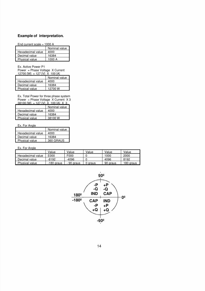
Example of interpretation.
End current scale = 1000 A
Nominal value
Hexadecimal value 4000Decimal value 16384
Physical value 1000 A
Ex. Active Power P1Power = Phase Voltage X Current12700 [W] = 127 [V] X 100 [A]
Nominal value
Hexadecimal value 4000
Decimal value 16384
Physical value 12700 W
Ex. Total Power for three phase systemPower = Phase Voltage X Current X 338100 [W] = 127 [V] X 100 [A] X 3
Nominal value
Hexadecimal value 4000
Decimal value 16384
Physical value 38100 W
Ex. For Angle
Nominal value
Hexadecimal value 4000
Decimal value 16384
Physical value 360 GRAUS
Ex. For Angle
Value Value Value Value ValueHexadecimal value E000 F000 0 1000 2000
Decimal value -8192 -4096 0 4096 8192
Physival value -180 graus - 90 graus 0 graus 90 graus 180 graus
180º
-180º0º
90º
-P
-P
+P
+P
-Q
+Q
-Q
+Q
IND
CAP
CAP
IND
-90º
7/24/2019 MuMGE144EN
http://slidepdf.com/reader/full/mumge144en 15/18
15
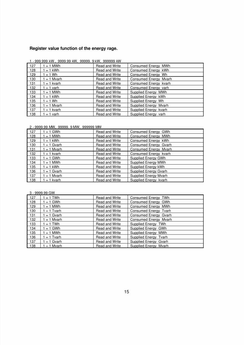
Register value function of the energy rage.
1 - 999.999 kW , 9999.99 kW, 99999. 9 kW, 999999 kW127 1 = 1 MWh Read and Write Consumed Energy MWh
128 1 = 1 kWh Read and Write Consumed Energy kWh
129 1 = 1 Wh Read and Write Consumed Energy Wh
130 1 = 1 Mvarh Read and Write Consumed Energy Mvarh
131 1 = 1 kvarh Read and Write Consumed Energy kvarh
132 1 = 1 varh Read and Write Consumed Energy varh
133 1 = 1 MWh Read and Write Supplied Energy MWh
134 1 = 1 kWh Read and Write Supplied Energy kWh
135 1 = 1 Wh Read and Write Supplied Energy Wh
136 1 = 1 Mvarh Read and Write Supplied Energy Mvarh
137 1 = 1 kvarh Read and Write Supplied Energy kvarh
138 1 = 1 varh Read and Write Supplied Energy varh
2 - 9999.99 MW, 99999. 9 MW, 999999 MW
127 1 = 1 GWh Read and Write Consumed Energy GWh
128 1 = 1 MWh Read and Write Consumed Energy MWh
129 1 = 1 kWh Read and Write Consumed Energy kWh
130 1 = 1 Gvarh Read and Write Consumed Energy Gvarh
131 1 = 1 Mvarh Read and Write Consumed Energy Mvarh
132 1 = 1 kvarh Read and Write Consumed Energy kvarh
133 1 = 1 GWh Read and Write Supplied Energy GWh
134 1 = 1 MWh Read and Write Supplied Energy MWh
135 1 = 1 kWh Read and Write Supplied Energy kWh
136 1 = 1 Gvarh Read and Write Supplied Energy Gvarh
137 1 = 1 Mvarh Read and Write Supplied Energy Mvarh
138 1 = 1 kvarh Read and Write Supplied Energy kvarh
3 - 9999.99 GW
127 1 = 1 TWh Read and Write Consumed Energy TWh
128 1 = 1 GWh Read and Write Consumed Energy GWh
129 1 = 1 MWh Read and Write Consumed Energy MWh
130 1 = 1 Tvarh Read and Write Consumed Energy Tvarh
131 1 = 1 Gvarh Read and Write Consumed Energy Gvarh
132 1 = 1 Mvarh Read and Write Consumed Energy Mvarh
133 1 = 1 TWh Read and Write Supplied Energy TWh
134 1 = 1 GWh Read and Write Supplied Energy GWh
135 1 = 1 MWh Read and Write Supplied Energy MWh
136 1 = 1 Tvarh Read and Write Supplied Energy Tvarh
137 1 = 1 Gvarh Read and Write Supplied Energy Gvarh138 1 = 1 Mvarh Read and Write Supplied Energy Mvarh
7/24/2019 MuMGE144EN
http://slidepdf.com/reader/full/mumge144en 16/18
16
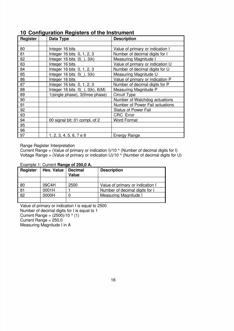
10 Configuration Registers of the InstrumentRegister Data Type Description
80 Integer 16 bits Value of primary or indication I
81 Integer 16 bits 0, 1, 2, 3 Number of decimal digits for I
82 Integer 16 bits 0(_), 3(k) Measuring Magnitude I83 Integer 16 bits Value of primary or indication U
84 Integer 16 bits 0, 1, 2, 3 Number of decimal digits for U
85 Integer 16 bits 0(_), 3(k) Measuring Magnitude U86 Integer 16 bits Value of primary or indication P
87 Integer 16 bits 0, 1, 2, 3 Number of decimal digits for P
88 Integer 16 bits 0(_), 3(k), 6(M) Measuring Magnitude P89 1(single phase), 3(three phase) Circuit Type
90 Number of Watchdog actuations
91 Number of Power Fail actuations92 Status of Power Fail
93 CRC Error94 00 signal bit; 01 compl. of 2 Word Format
95
9697 1, 2, 3, 4, 5, 6, 7 e 8 Energy Range
Range Register InterpretationCurrent Range = (Value of primary or indication I)/10 ^ (Number of decimal digits for I)Voltage Range = (Value of primary or indication U)/10 ^ (Number of decimal digits for U)
Example 1: Current Range of 250,0 A.
Register Hex. Value Decimal
Value
Description
80 09C4H 2500 Value of primary or indication I
81 0001H 1 Number of decimal digits for I
82 0000H 0 Measuring Magnitude I
Value of primary or indication I is equal to 2500Number of decimal digits for I is equal to 1Current Range = (2500)/10 ^ (1)Current Range = 250,0Measuring Magnitude I in A
7/24/2019 MuMGE144EN
http://slidepdf.com/reader/full/mumge144en 17/18
17
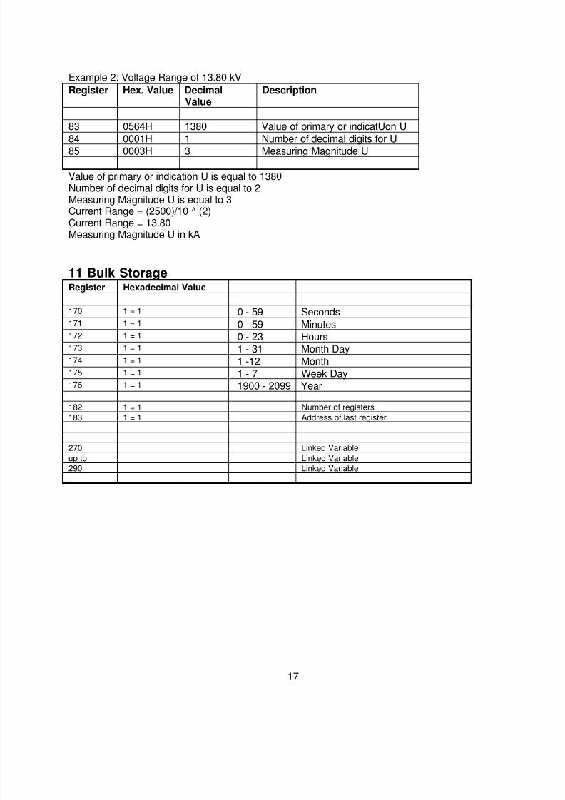
Example 2: Voltage Range of 13.80 kV
Register Hex. Value DecimalValue
Description
83 0564H 1380 Value of primary or indicatUon U
84 0001H 1 Number of decimal digits for U85 0003H 3 Measuring Magnitude U
Value of primary or indication U is equal to 1380Number of decimal digits for U is equal to 2Measuring Magnitude U is equal to 3Current Range = (2500)/10 ^ (2)Current Range = 13.80Measuring Magnitude U in kA
11 Bulk StorageRegister Hexadecimal Value
170 1 = 1 0 - 59 Seconds171 1 = 1 0 - 59 Minutes172 1 = 1 0 - 23 Hours173 1 = 1 1 - 31 Month Day174 1 = 1 1 -12 Month175 1 = 1 1 - 7 Week Day176 1 = 1 1900 - 2099 Year
182 1 = 1 Number of registers
183 1 = 1 Address of last register
270 Linked Variable
up to Linked Variable
290 Linked Variable
7/24/2019 MuMGE144EN
http://slidepdf.com/reader/full/mumge144en 18/18
18
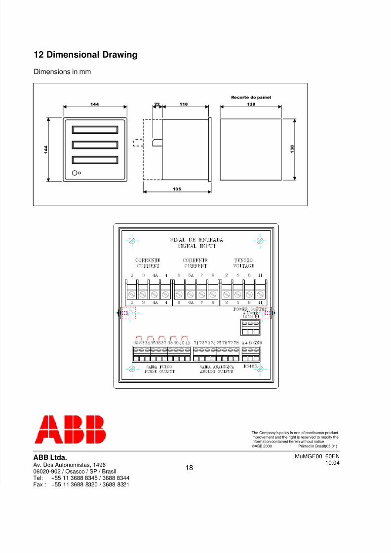
12 Dimensional Drawing
Dimensions in mm
ABB Ltda.Av. Dos Autonomistas, 149606020-902 / Osasco / SP / BrasilT l 55 11 3688 8345 / 3688 8344
The Company’s policy is one of continuous productimprovement and the right is reserved to modify theinformation contained herein without notice
©ABB 2000 Printed in Brasil(05.01)
MuMGE00_60EN10.04


