Embed Size (px)
Citation preview

Doc. no.MYZZ-OM0013Q
PRODUCT NAME
Mechanically jointed rodless cylinder Basic short type (Rubber bumper), Basic standard type (Air cushion)
Slide bearing guide type (Air cushion)
MODEL / Series / Product Number MY3A/B/M Series

Contents
Safety Instructions ---------------------- P. 2 to 3 1. Product Specifications
1.1 Specifications ---------------------------- P. 4 2. Operation and Mounting
2.1 Air Supply -------------------- P. 5 2.2 Operating Environment ----------------- P. 6 2.3 Design ------------------ P. 6 2.4 Mounting and Installation ------------------ P. 8 2.5 Piping -------------------- P. 11 2.6 Speed Control ------------------- P. 12 2.7 Shock Absorbing Mechanism --------------- P. 12 2.8 Directional Control --------------- P. 14 2.9 Mounting of Auto Switch -------------- P. 14
3. Maintenance and Inspection
3.1 Inspection ------------------- P. 15 3.2 Maintenance ------------ P. 15 3.3 Replacement Parts -------------- P. 15
4. Troubleshooting
------------------- P. 16
-1-

Safety Instructions These safety instructions are intended to prevent hazardous situations and/or equipment damage. These instructions indicate the level of potential hazard with the labels of “Caution,” “Warning” or “Danger.” They are all important notes for safety and must be followed in addition to International Standards (ISO/IEC)*1)
*1) ISO 4414: Pneumatic fluid power -- General rules relating to systems. , and other safety regulations.
ISO 4413: Hydraulic fluid power -- General rules relating to systems. IEC 60204-1: Safety of machinery -- Electrical equipment of machines .(Part 1: General requirements) ISO 10218-1992: Manipulating industrial robots -Safety. etc.
Caution Caution indicates a hazard with a low level of risk which, if not avoided, could result in minor or moderate injury.
Warning Warning indicates a hazard with a medium level of risk which, if not avoided, could
result in death or serious injury.
Danger Danger indicates a hazard with a high level of risk which, if not avoided, will result in death or serious injury.
Warning 1. The compatibility of the product is the responsibility of the person who designs the equipment or
decides its specifications. Since the product specified here is used under various operating conditions, its compatibility with specific equipment must be decided by the person who designs the equipment or decides its specifications based on necessary analysis and test results. The expected performance and safety assurance of the equipment will be the responsibility of the person who has determined its compatibility with the product. This person should also continuously review all specifications of the product referring to its latest catalog information, with a view to giving due consideration to any possibility of equipment failure when configuring the equipment.
2. Only personnel with appropriate training should operate machinery and equipment. The product specified here may become unsafe if handled incorrectly. The assembly, operation and maintenance of machines or equipment including our products must be performed by an operator who is appropriately trained and experienced.
3. Do not service or attempt to remove product and machinery/equipment until safety is confirmed. 1.The inspection and maintenance of machinery/equipment should only be performed after measures to
prevent falling or runaway of the driven objects have been confirmed. 2.When the product is to be removed, confirm that the safety measures as mentioned above are implemented and the power from any appropriate source is cut, and read and understand the specific product precautions of all relevant products carefully. 3. Before machinery/equipment is restarted, take measures to prevent unexpected operation and malfunction.
4. Contact SMC beforehand and take special consideration of safety measures if the product is to be used in any of the following conditions. 1. Conditions and environments outside of the given specifications, or use outdoors or in a place exposed to direct sunlight. 2. Installation on equipment in conjunction with atomic energy, railways, air navigation, space, shipping,
vehicles, military, medical treatment, combustion and recreation, or equipment in contact with food and beverages, emergency stop circuits, clutch and brake circuits in press applications, safety equipment or other applications unsuitable for the standard specifications described in the product catalog.
3. An application which could have negative effects on people, property, or animals requiring special safety analysis.
4.Use in an interlock circuit, which requires the provision of double interlock for possible failure by using a mechanical protective function, and periodical checks to confirm proper operation.
-2-
Safety Instructions
Caution 1.The product is provided for use in manufacturing industries.
The product herein described is basically provided for peaceful use in manufacturing industries. If considering using the product in other industries, consult SMC beforehand and exchange specifications or a contract if necessary. If anything is unclear, contact your nearest sales branch.
Limited warranty and Disclaimer/Compliance Requirements The product used is subject to the following “Limited warranty and Disclaimer” and “Compliance Requirements”. Read and accept them before using the product.
Limited warranty and Disclaimer 1.The warranty period of the product is 1 year in service or 1.5 years after the product is delivered,
whichever is first.∗2)
Also, the product may have specified durability, running distance or replacement parts. Please
consult your nearest sales branch. 2. For any failure or damage reported within the warranty period which is clearly our responsibility, a replacement product or necessary parts will be provided. This limited warranty applies only to our product independently, and not to any other damage
incurred due to the failure of the product. 3. Prior to using SMC products, please read and understand the warranty terms and disclaimers
noted in the specified catalog for the particular products.
∗2) Vacuum pads are excluded from this 1 year warranty. A vacuum pad is a consumable part, so it is warranted for a year after it is delivered.
Also, even within the warranty period, the wear of a product due to the use of the vacuum pad or failure due to the deterioration of rubber material are not covered by the limited
warranty.
Compliance Requirements 1. The use of SMC products with production equipment for the manufacture of weapons of mass
destruction (WMD) or any other weapon is strictly prohibited. 2. The exports of SMC products or technology from one country to another are governed by the
relevant security laws and regulations of the countries involved in the transaction. Prior to the shipment of a SMC product to another country, assure that all local rules governing that export are known and followed.
The product is provided for use in manufacturing industries. The product herein described is basically provided for peaceful use in manufacturing industries. If considering using the product in other industries, consult SMC beforehand and exchange specifications or a contract if necessary. 契約などを行ってください。
The product is provided for use in manufacturing industries. The product herein described is basically provided for peaceful use in manufacturing industries. If considering using the product in other industries, consult SMC beforehand and exchange specifications or a contract if necessary. 契約などを行ってください。
-3-
1. Product Specifications 1-1. Specifications
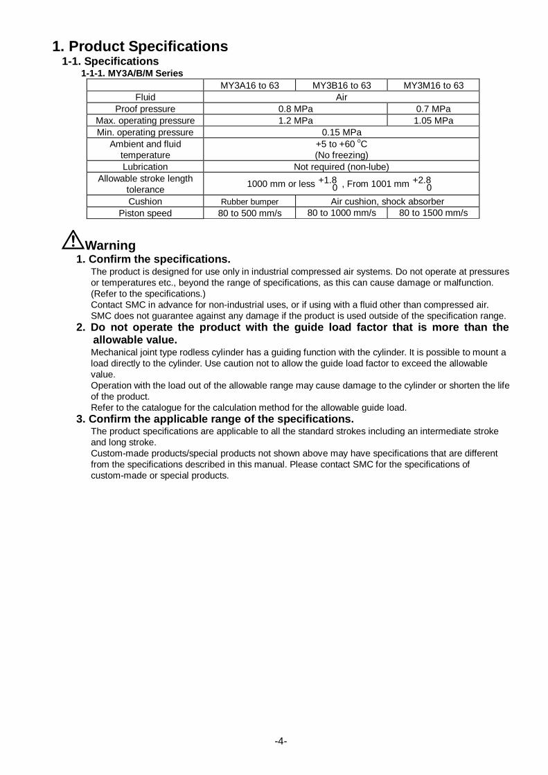
1-1-1. MY3A/B/M Series MY3A16 to 63 MY3B16 to 63 MY3M16 to 63
Fluid Air Proof pressure 0.8 MPa 0.7 MPa
Max. operating pressure 1.2 MPa 1.05 MPa Min. operating pressure 0.15 MPa
Ambient and fluid temperature
+5 to +60 o
(No freezing) C
Lubrication Not required (non-lube) Allowable stroke length
tolerance 1000 mm or less +1.8 0 , From 1001 mm +2.8
0
Cushion Rubber bumper Air cushion, shock absorber Piston speed 80 to 500 mm/s 80 to 1000 mm/s 80 to 1500 mm/s
Warning 1. Confirm the specifications.
The product is designed for use only in industrial compressed air systems. Do not operate at pressures or temperatures etc., beyond the range of specifications, as this can cause damage or malfunction. (Refer to the specifications.) Contact SMC in advance for non-industrial uses, or if using with a fluid other than compressed air. SMC does not guarantee against any damage if the product is used outside of the specification range.
2. Do not operate the product with the guide load factor that is more than the allowable value. Mechanical joint type rodless cylinder has a guiding function with the cylinder. It is possible to mount a load directly to the cylinder. Use caution not to allow the guide load factor to exceed the allowable value. Operation with the load out of the allowable range may cause damage to the cylinder or shorten the life of the product. Refer to the catalogue for the calculation method for the allowable guide load.
3. Confirm the applicable range of the specifications. The product specifications are applicable to all the standard strokes including an intermediate stroke and long stroke. Custom-made products/special products not shown above may have specifications that are different from the specifications described in this manual. Please contact SMC for the specifications of custom-made or special products.
-4-

Caution 1. Air leakage due to removal of the seal belt
Mechanical joint type rodless cylinders may have a temporary external air leakage in some operating conditions due to the product construction when negative pressure is generated inside the cylinder with external force, inertial force, or etc. When this happens, refer to "How to put back the seal belt when it comes off" shown below and carefully return the seal belt to the position not to damage the seal belt. Damage to the seal belt may cause permanent air leakage.
2. Operation and Mounting
2-1. Air supply The compressed air supplied to the cylinder should be filtered by SMC AF series air filter and regulated to the specified set pressure by SMC AR series regulator.
Warning 1. Use clean air.
Do not use compressed air that contains chemicals, synthetic oils including organic solvents, salts or corrosive gases etc., as this can cause damage or malfunction.
-5-

Caution 1. Install an air filter.
Install an air filter upstream near the valve. Select an air filter with a filtration size of 5μm or smaller. 2. Install an aftercooler, air dryer, or water separator before the filter.
Compressed air that contains excessive foreign material may cause malfunction of valves and other pneumatic equipment.
3. Discharge condensates regularly. If condensate in the drain bowl is not emptied on a regular basis, the condensate will overflow and allow it to enter the compressed air lines. This will cause a malfunction of pneumatic equipment. If the drain bowl is difficult to check and remove, installation of a drain bowl with an auto drain option is recommended.
4. Use the product within the specified fluid and ambient temperature range. When operating at temperatures below 5o
5. Usage of ultra dry air as fluid
C, moisture in the circuit may freeze and cause damage to the seals or a malfunction. Use within the specified operating temperature range.
If ultra dry air is used as a fluid, the lubrication characteristics of the equipment will deteriorate and this can affect the reliability (life) of the product. Contact SMC before using with ultra dry air.
6. Lubrication of non-lubricating cylinder The product has been lubricated for life at the manufacturer's and does not require lubrication in service. If a lubricant is used in the system, use turbine oil Class 1 (with no additive) ISO VG32. Once lubricant is used in the system, lubrication must be continued because the original lubricant applied during manufacturing will be washed away. For detailed information regarding the quality of the compressed air described above, refer to SMC's "Air Cleaning Systems".
2-2. Operating Environment
Warning 1. Do not use in environments where there is a danger of corrosion. 2. Do not use in direct sunlight. 3. Do not operate in a location subject to vibration or impact. 4. When using auto switches do not operate in an environment with strong
magnetic fields. 5. Grease base oil can decrease depending on external environment and operating
conditions. This may reduce the lubrication performance and shorten the life of the equipment.
6. Avoid using the product in an environment that is exposed to foreign matter. If the cylinder is used in an environment where there is possible contact with cutting chips, dust (paper, yarn debris, etc.), spatter or any liquids (cutting oil, light oil, moisture, etc.), debris may enter the cylinder and cause operation failure. Ifoperating in such an environment is unavoidable, mount a cover to the product or mount the product on the ceiling. Note that some liquid coolant may negatively impact the sealing parts.
7. Avoid storing the product in high temperature and/or humid conditions. Rust may be generated or the sealing parts may be deteriorated in such an environment.
2-3. Design The compatibility of the product is the responsibility of the person who designs the equipment or decides its specifications.
-6-

Warning 1. There is a possibility of dangerous sudden action by cylinders if force is
changed due to twisting of sliding parts of machinery. In such cases, human injury may occur; e.g., by catching hands or feet in the machinery, or damage to the machinery itself may occur. Therefore, the machine should be designed to operate smoothly and avoid such dangers.
2. A deceleration circuit or shock absorber etc. may be required. When a driven object moves at a high speed or the load is heavy, it may be unfeasible for just the cylinder's air cushion or shock absorber to absorb the shock. Therefore provide a speed reduction circuit to reduce the cylinder speed or install an external shock absorber to dampen the shock. If these countermeasures are taken, confirm the rigidity of the equipment carefully.
3. A protective cover is recommended to minimize the risk of personal injury. If the driven object or moving parts of the product will pose a hazard to humans, a construction that prevents direct contact with the exposed area must be provided. For product with stroke adjusting unit, the clearance between the slide table (slider) and the stroke adjusting unit at the stroke end is small. When the cylinder is operating at a high speed and high frequency, the surface temperature of the cylinder tube increases, and may cause injury to personnel.
4. Ensure mounting fasteners will not loosen. When the product operates with high frequency or is installed where there is a lot of vibration, ensure that all parts remain secure.
5. Design the system so external forces do not exceed the maximum specifications. The product can break, causing a risk of injury to personnel or damage to equipment.
6. The cylinder generates a large force. Install on a sufficiently rigid mounting base, taking this force into consideration. There is a risk of injury to personnel or damage to equipment.
7. Consider an air pressure drop that is caused by a power source related malfunction. There is a danger of workpieces dropping if there is a decrease of thrust due to a drop in circuit pressure caused by a power source malfunction etc. Therefore, safety equipment should be installed to prevent damage to machinery and/or injury to personnel. Suspension equipment and lifting devices also require measures to prevent dropping.
8. Consider the possibility of power source related malfunctions. For equipment that relies on power sources such as compressed air, electricity, or hydraulic pressure, adopt countermeasures to prevent the equipment from causing a hazard to humans or damage to the equipment in the event of malfunction.
9. Consider the behavior of an emergency stop. A safety system should be devised so that if personnel engage the emergency stop, or if a safety device is tripped during a system malfunction (such as a power source malfunction), the movement of the cylinder will not cause a hazard to personnel or damage the equipment.
10. Consider the action when operation is restarted after an emergency stop or abnormal stop. Design the machinery so that personal injury or damage to equipment will not occur upon restart of operation. Install manually controlled equipment for safety when the actuator has to be reset to the starting position.
Caution 1. Operate the product within a range such that the piston will not collide and be
damaged at the stroke end. If the piston with inertia force is stopped by colliding with the cover at the stroke end, operate the cylinder within a range that will not cause damage. Refer to the cylinder model selection table for the range that will not cause damage.
-7-

2. Install a shock absorber to prevent impact load being appliedto the moving slider. MY3 series product has a light-weight structure. The cylinder may breakif the slide table is stopped forcibly at the intermediate position or if the load is applied to the slide table with an impact. To reduce the impact applied to the cylinder to less than the allowable value, install a shock absorber when operating the product. Refer to "Shock Absorbing Mechanism" for selecting shock absorber.
3. Mount an intermediate support to a long stroke cylinder. For a long stroke cylinder, mount an intermediate support to prevent vibration or external force from being applied to the product or to prevent deflection of the body due to the product's own weight.
4. When using an external guide together with the cylinder, hold the load only with the external guide, and only use the cylinder as a driving source. The longer the stroke, the greater the amount of variation in the center axis. Therefore, a method of connection which can absorb the displacement (i.e. floating mechanism) should be considered. A cylinder (Basic series MY3A/MY3B) that is suitable to be used as a driving source and a floating joint as an option are available. Please refer to the catalog for details. The floating joint pin may break during adjustment or due to piston lurching especially when the load is large.
5. The workpiece may vibrate when the cylinder is stopped by a stroke adjustment unit while the workpiece and the cylinder are in floating connection. Floating mechanism releases the force by making a minute gap. Therefore, the workpiece may vibrate due to the minute gap of the floating mechanism when the cylinder is stopped by an external guide and floating bracket when the cylinder is installed near a vibration source. To prevent the state describedabove, make the workpiece to be received by an external shock absorber.
6. Avoid using cylinders for synchronized operations. Even if multiple cylinders are initially set to the same speed, their speeds may vary due to changes in operating conditions. In such a case, an excessive moment will be applied to the slide tables and it may cause operation failure. Do not design a circuit using more than one cylinder in a synchronized operation to transfer one load.
7. Grease has been applied on the cylinder surface. Do not wipe it off. Removing the grease may cause malfunction due to lack of lubrication.
8. The pre-applied grease may result in base oil seeping out. The base oil of the grease in the cylinder may seep out of the tube, cover, slider or guide sliding part depending on the operating conditions (ambient temperature 40o
C or more, pressurized condition, low frequency operation).
2-4. Mounting and Installation 2-4-1. Mounting Surface
It is recommended to mount the cylinder on a surface with a high flatness (e.g. a machined surface). If the mounting surface flatness is questionable, use shims to adjust the flatness to make it possible for the slide table to operate with the minimum operating pressure for the entire stroke. Mounting surface of the slide table is machined with high accuracy. Flatness of the mounting surface of the mating part must be 0.03 mm at maximum. When the flatness cannot be obtained, use shims for adjustment of the mounting surface of the cylinder as shown above.
2-4-2. Mounting - To mount the product body, install the head cover from the upper side of the body and fix it with
bolts.
Fig. 1: Fixing the product from the upper side
◎
-8-

- At least 5 mm of both ends of the cylinder tube have to contact with the attachment point. (See Fig. 2)
Fig. 2
- If the cylinder is mounted on the ceiling or wall, use side supports, in addition to the fixing bolts on the head cover, to support both ends of the cylinder tube. (See Fig. 3)
Fig. 3
- Do not mount a slide table on the fixed equipment surface as shown in Fig. 4. It may cause damage or malfunction since an excessive load is applied to the bearing.
- Consult with SMC when mounting in a cantilevered way (Fig. 5). Deflection of the cylinder tube
may cause malfunction.
Fig. 4 Mounting with a slide table (slider) (Prohibited) (Consult with SMC)
Fig. 5 Mounting in a cantilevered way
- The cylinder tube may deflect due to its own weight, load, or etc. When the cylinder tube is
deflected, hold the cylinder at the intermediate position using the side support. Support spacing (L) shown in Fig. 6 must be the values shown in Fig. 7 or less.
Note) Using the side support for mounting a cylinder that has mounting surfaces that are not flat
enough may cause failure. Adjust the mounting surface level when using the side support.
Fig. 6
m L
m
L
m
L L
-9-

Fig. 7
- When using the product that has a stroke that exceeds the stroke fine adjustment range, use an intermediate fixing spacer. Refer to the table below for the stroke fine adjustment range and the stroke adjustment range when using the intermediate fixing spacer.
When using an intermediate fixing spacer for the MY3B series, the maximum operation speed is 800 mm/s (500 mm/s for the MY3B16).
Table 1 Stroke adjustment range (Without spacer, with short spacer, with long spacer)
Warning 1. Secure all the mounting screws firmly to mount the slide table.
If not, the slide table and/or the mounting screws may be damaged, and the workpiece may drop. 2. Carefully lift the cylinder to avoid injuries to hands and fingers.
Use crane for raising heavy cylinders with large port or long stroke.
Caution 1. Do not apply a strong impact or excessive moment to the slide table.
The slide table is supported by a resin slide bearing. Do not apply a strong impact or excessive moment when mounting a workpiece.
2. When connecting a load with an external guide mechanism, be sure to align carefully.
3. Do not hit or grip the cylinder tube with objects. Scratches or dents in the external circumference of the cylinder tube may damage the bearing and/or the scraper, and it may cause operation failure.
4. Use caution not to allow foreign matter such as cutting particles to enter the cylinder from the air supply port. Foreign matter such as cutting particles or dust entering the product during the product mounting may cause operation failure.
-10 -20 -30 -40 -50 -60 -70 -80
Long spacer
20 to 30
0 to 24MY3*63
MY3*40/50
MY3*16/20
MY3*25/320 to 12Without spacer
12 to 24
Without spacer
0 to 10Short
spacer
10 to 20
24 to 36Long
spacer0 to 16
Without spacer16 to 32
Short spacer32 to 48
Long spacer
Short spacer
Without spacer24 to 48
Short spacer48 to 72
Long spacer
0
-10-

5. Do not change the setting of the guide adjusting part without careful consideration. The guide has been adjusted as default. Readjustment will not be required in normal operating conditions. If play occurs, check the operating conditions and contact SMC.
6. Do not fix the stroke adjustment unit at an intermediate position. An error may result depending on the collision energy.
7. Do not use the product until you have verified that the equipment can operate properly. After mounting or repair, connect the air and power supplies to the product and perform appropriate functional and leakage inspections to check it is mounted properly.
2-5. Piping Ports on the head cover for piping connection can be selected as preferred. Refer to the port variation diagram (see Fig. 8) to find the most suitable ports for piping connection. When the stroke adjustment unit is used, the fittings mountable on the front or back port will be limited. Refer to the catalog for the mountable fittings.
Applicable cylinder Port variations MY3A16 to 63 MY3B16 to 63 MY3M16 to 63
Fig. 8
Caution 1. Before piping
Before piping, perform air blow (flushing) or cleaning to remove cutting chips, cutting oil, dust, etc. from the pipe.
2. Sealant tape When screwing piping or fittings into ports, ensure that chips from the pipe threads or sealing material do not enter the piping. If sealant tape is used, leave 1.5 to 2 threads exposed at the end of threads.
Fig. 9 Wrapping of sealant tape
-11-

2-6. Speed control When the piston speed is adjusted, install SMC AS series speed controller near the air supply port to adjust the speed to the specified value. There are two methods of speed adjustment, one is to restrict air supplied to the product, and the other is to restrict air exhausted from the product. Normally, the latter method should be adopted.
Caution 1. Use a speed controller to adjust the cylinder drive speed, gradually increasing
from a low speed to the desired speed setting. 2. Performance at constant speed
Mechanical joint type rodless cylinder has a larger fluctuation in speed compared to the rod air cylinder due to its construction. Consult SMC for the product usage for an application which requires a constant speed operation.
2-7. Shock Absorbing Mechanism 2-7-1. Rubber cushion (MY3A series)
As shock absorbing stroke of rubber cushion is short, additional cushioning equipment is necessary for stroke adjustment. If positioning accuracy is required for the stop position at the stroke end, consider installing an external shock absorber or switching to the air cushion type (MY3B series). The stop position of the rubber cushion type product varies depending on the operating pressure. For alignment at the stroke end, refer to the "Rubber Bumper Displacement" graph shown in the catalog and find the guideline for the stroke end position in operation. Then, find the incremental displacement at the operating pressure in the graph and add it to the stroke end position at no pressurization. The "Rubber Bumper Displacement" graph shows displacement when the product is mounted horizontally. For the product mounted horizontally, convert the force generated by the self-weight (load mass + slider weight) into the air pressure. Then, subtract the converted air pressure from the operating pressure when the cylinder is at the upper stroke end, and add the converted air pressure to the operating pressure when the cylinder is at the lower stroke end to calculate the displacement from the graph. (Refer to the catalog for the weight of the slider.)
2-7-2. Air Cushion The cushion needle is adjusted to default when the product is shipped. The cushion needle on the cover should be readjusted when the product is put into service, based upon factors such as the size of the load and the operating speed. By turning the cushion needle in clockwise direction, air is restricted more and the cushion's effectiveness is improved. Depending on the stroke adjustment amount, air cushion performance will be diminished or will not work.
2-7-3. Stroke Adjustment Unit - Fixation of the unit body
The unit body can be fixed by evenly tightening the four stroke adjusting unit retaining screws. (See Fig. 10 , 11 and Table 3)
Fig. 10 MY3B Fig. 11 MY3M
-12-
Unit: Nm Unit: Nm
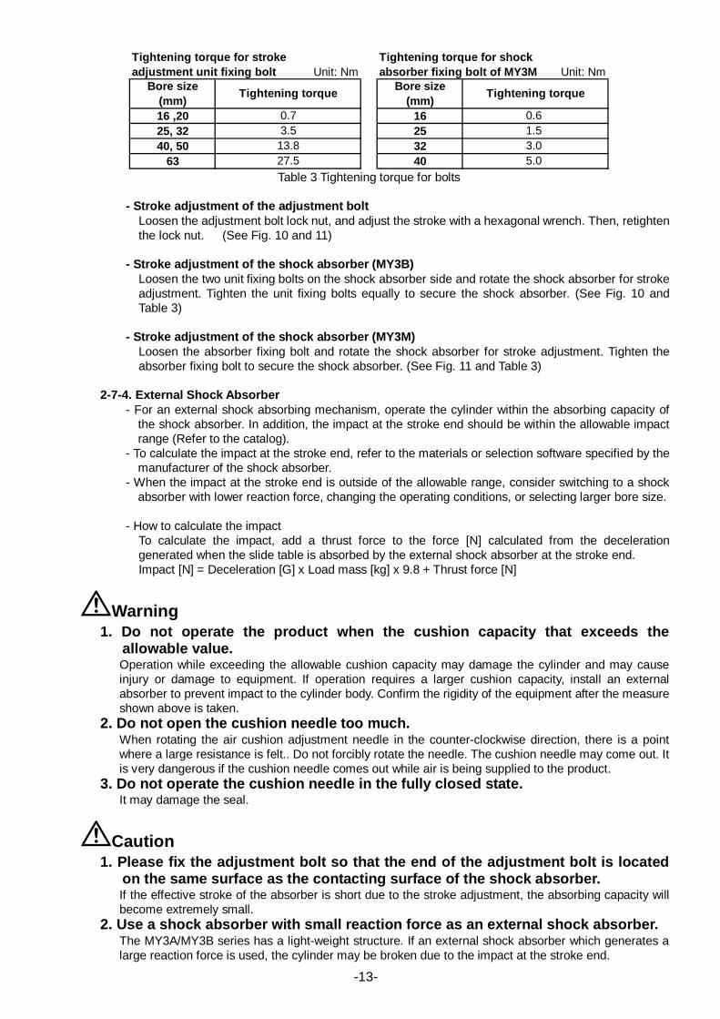
16 ,20 1625, 32 2540, 50 32
63 40
Tightening torque
Tightening torque for shockabsorber fixing bolt of MY3M
0.73.5 1.5
0.6
Tightening torque for strokeadjustment unit fixing bolt
Bore size(mm)
Bore size(mm)Tightening torque
13.827.5 5.0
3.0
Table 3 Tightening torque for bolts
- Stroke adjustment of the adjustment bolt
Loosen the adjustment bolt lock nut, and adjust the stroke with a hexagonal wrench. Then, retighten the lock nut. (See Fig. 10 and 11)
- Stroke adjustment of the shock absorber (MY3B) Loosen the two unit fixing bolts on the shock absorber side and rotate the shock absorber for stroke adjustment. Tighten the unit fixing bolts equally to secure the shock absorber. (See Fig. 10 and Table 3)
- Stroke adjustment of the shock absorber (MY3M) Loosen the absorber fixing bolt and rotate the shock absorber for stroke adjustment. Tighten the absorber fixing bolt to secure the shock absorber. (See Fig. 11 and Table 3)
2-7-4. External Shock Absorber - For an external shock absorbing mechanism, operate the cylinder within the absorbing capacity of
the shock absorber. In addition, the impact at the stroke end should be within the allowable impact range (Refer to the catalog).
- To calculate the impact at the stroke end, refer to the materials or selection software specified by the manufacturer of the shock absorber.
- When the impact at the stroke end is outside of the allowable range, consider switching to a shock absorber with lower reaction force, changing the operating conditions, or selecting larger bore size.
- How to calculate the impact
To calculate the impact, add a thrust force to the force [N] calculated from the deceleration generated when the slide table is absorbed by the external shock absorber at the stroke end. Impact [N] = Deceleration [G] x Load mass [kg] x 9.8 + Thrust force [N]
Warning 1. Do not operate the product when the cushion capacity that exceeds the
allowable value. Operation while exceeding the allowable cushion capacity may damage the cylinder and may cause injury or damage to equipment. If operation requires a larger cushion capacity, install an external absorber to prevent impact to the cylinder body. Confirm the rigidity of the equipment after the measure shown above is taken.
2. Do not open the cushion needle too much. When rotating the air cushion adjustment needle in the counter-clockwise direction, there is a point where a large resistance is felt.. Do not forcibly rotate the needle. The cushion needle may come out. It is very dangerous if the cushion needle comes out while air is being supplied to the product.
3. Do not operate the cushion needle in the fully closed state. It may damage the seal.
Caution 1. Please fix the adjustment bolt so that the end of the adjustment bolt is located
on the same surface as the contacting surface of the shock absorber. If the effective stroke of the absorber is short due to the stroke adjustment, the absorbing capacity will become extremely small.
2. Use a shock absorber with small reaction force as an external shock absorber. The MY3A/MY3B series has a light-weight structure. If an external shock absorber which generates a large reaction force is used, the cylinder may be broken due to the impact at the stroke end.
-13-

3. The impact calculated by the selection software may be different from the actual value. Please select the product model considering the margin of the operating conditions. The impact for an adjustable shock absorber calculated by the selection software will be adjusted appropriately so that the reaction force of the absorber is maximum value. If it is not adjusted appropriately, the actual impact will be larger than the impact calculated by the selection software, leading to breakage of the cylinder.
2-8. Directional control To change the operating direction of the cylinder, mount an applicable solenoid valve selected from SMC's range of solenoid valves.
Warning 1. Design a circuit to prevent sudden action of a driven object.
When the product is actuated by an exhaust center type directional control valve or when one side of the piston is pressurized with air exhaust, such as when the product is started after the exhaust of the residual pressure from the circuit, driven objects may act suddenly at high speed. In such cases, injury may occur, such as hands or feet getting caught in the machinery, or damage to the machinery itself may occur. Design the machinery using equipment to prevent sudden action.
2. Intermediate stop Due to the compressibility of air, it is difficult for this product to make a piston stop at the required intermediate position accurately and precisely. Mechanical joint rodless cylinder has a special seal in the construction, and this causes a minimal amount of external air leakage. A three position closed center type directional control valve may not hold the slide table in the intermediate position for an extended period of time, and the speed may not be controlled when restarting the operation. Rodless cylinder has the same pressure receiving areas in all the pressure chambers. The table will also stop with a circuit that has air supply from both sides. Use a circuit that controls pressure supply to both sides that uses a three position pressure center type directional control valve for intermediate stop. For holding the intermediate stop for an extended period of time, use a device to prevent it from moving for designing a circuit. Consult SMC for details.
2-9. Mounting of Auto Switch Mount the auto switch according to the following procedure.
1. Hold the switch spacer with fingers, and push it into the groove as shown in Fig. 12. 2. Confirm that the switch spacer is mounted correctly. 3. After specifying the detecting position, tighten the mounting screw (M2.5) delivered together with the
product to fix the auto switch.
Note: For the tightening of the auto switch mounting screw, use a precision screwdriver with a handle diameter of approximately 5 to 6 mm. Use the tightening torque of approximately 0.05 to 0.1 Nm. As a guide, turn 90o
from the position where the mounting screw starts to become tight.
Note: Cylinder with switch includes a switch spacer (BMY3-016) in the package. When only switch is
ordered, order the switch spacer separately. Refer to the catalog for the correct mounting position.
Fig. 12
-14-
Caution 1. For the handling of the auto switch, refer to the Operation Manual of the auto
switch. 2. Do not let objects drop onto the product or apply with an excessive impact to the
product when handling. 3. Avoid wiring that applies repeated bending stress and/or tensile force on the
lead wire. 4. It is possible to mount an auto switch in the intermediate position, but the
cylinder speed for the switch detection needs to be adjusted to 300 mm/sec. or less in accordance with the response time of the load relay, etc.
5. When operating multiple cylinders with the auto switch in parallel, separate the cylinders, maintaining a minimum separation distance of at least 40 mm.
3. Maintenance
3-1. Inspections 3-1-1. Daily Check
1) Smoothness of the operation 2) Changes in piston speed and cycle time 3) Smooth movement of the slide table for the entire stroke
3-1-2. Regular Check 1) Any loose mounting bolts: cylinder mounting, work piece mounting bolts, etc. 2) Smoothness of the operation 3) Changes in the piston speed and cycle time 4) Smooth movement of the slide table for the entire stroke 5) Air leaks 6) Any scratches or damages to the cylinder 7) No drain in the air filter and/or piping 8) Increase in the play of the slider (slide table)
When check of the items shown above finds any problems with the cylinder, take the necessary countermeasures referring to the section "4. Troubleshooting".
3-2. Maintenance
Monthly application of grease to the slide bearing (guide) and the dust seal band may lengthen the life. Use the grease recommended by SMC. Grease pack part number: GR-S-010 (10g), GR-S-020 (20g)
3-3. Replacement Parts Refer to the catalog for the parts can be replaced.
Warning 1. Maintenance should be performed according to the items above.
Improper handling can cause damage or malfunction of equipment and machinery. 2. Removal of equipment, and supply/exhaust of compressed air
When the equipment is serviced, first confirm that measures are in place to prevent any dropping of driven objects and run-away of equipment, etc. Then turn off the supply pressure and power, exhaust all compressed air from the system using its residual pressure release function. Before restarting the equipment, confirm that measures are taken to prevent sudden action.
-15-

4. Troubleshooting
Failure Major causes Countermeasures Operation is not smooth. The speed or cycle time has changed. No operation
Misalignment of the workpiece and cylinder axis; or the guide axis of the workpiece and cylinder axis, application of external force to the cylinder due to usage of a cable bearer, etc.
Realign workpiece and cylinder Confirm that the cylinder operates smoothly without
air supplied to the cylinder. Consider using a Floating Bracket (available from SMC) or connecting pipes using a floating mechanism.
Operation at low speed Keep the specified range. Non-conforming air system configuration
Use appropriate size piping tube, fitting, directional control valve, speed controller, etc.
Lack of grease on the sliding surface
Add grease. (On the top surface and sliding surface of the cylinder tube, approximately 5 g/500 stroke) - Grease is lost due to infiltration of moisture such as drain. - Lubrication is stopped after it is lubricated once. - The product is operated in the environment in which it gets liquid splash.
Insufficient air pressure Supply adequate pressure. Take necessary countermeasures if any of the following applies. - Pressure source has decreased (including insufficient flow). - Incorrect setting of the regulator. - Clogging, disconnection, or bending of the piping.
Insufficient cylinder output Increase the operating pressure or the cylinder bore size.
It should be selected with the sufficient load factor taking resistance of the cylinder and peripherals into consideration.
Failure of the equipment other than the cylinder
Investigate components of concern one by one. Take necessary countermeasures if any of the
following applies. - Failure of the directional control valve. - The speed controller is not adjusted properly. - The speed controller has failed. - Clogging, disconnection, or bending of the piping. - Clogging of the filter, etc.
Abnormal stroke
Lodging of foreign matter. Check for foreign matter caught between the slider and the external stopper, etc.
Foreign matter got inside the cylinder.
Check for foreign matter, such as drain, inside the cylinder.
Air blowing-by Removal of the seal belt Refer to "How to put back the seal belt when it comes off" on page 5 in the section "1. Product Specifications", and return the seal belt into the specified position.
Wear of the seals Replace the seals with the new ones. Take necessary countermeasures if any of the following applies. - Application of a load larger than the allowable load. - Operation in an ambient temperature outside of the operating temperature range. - Shortage of grease. - Foreign matter entering the product.
-16-

Failure Major causes Countermeasures Damage to the parts.
Operation at high speed Adjust the speed by the speed controller and keep the specified range.
Excessive impact at the stroke end
Use a shock absorber which absorbs kinetic energy generated by the slider.
Overload or excessive moment
Select the cylinder model that keeps the guide load factor of the cylinder within the allowable range.
Action of external force Structural interference, unbalanced load or over-load may cause damage and/or deformation of the cylinder. Insure these conditions do not exist.
Large movement of the slider
Wear-out of the slide bearing The table can be readjusted if the wear of the slide bearing is not significant. Contact SMC for readjustment of the slide table. If the wear is significantly bad, it will be necessary to replace the bearing.
Wear or damage to the cam follower guide
Refer to the item "Damage to the parts" shown above, and take the countermeasures.
Wear-out or damage of the linear guide
Refer to the item "Damage to the parts" shown above, and take the countermeasures.
Damage of the parts around the bearing (guide)
Refer to the item "Damage to the parts" shown above, and take the countermeasures.
Caution Contact SMC if cylinder needs to be disassembled. Air leaks may occur if the seals
are damaged during disassembly. Disassembling or modifying the internal wiring will void the product's warranty. If you need it warranted, ask SMC for repair.
-17-

Revision history SZ Revised to the new format.
4-14-1, Sotokanda, Chiyoda-ku, Tokyo 101-0021 JAPAN Tel: + 81 3 5207 8249 Fax: +81 3 5298 5362 URL http://www.smcworld.com Note: Specifications are subject to change without prior notice and any obligation on the part of the manufacturer. © 2011 SMC Corporation All Rights Reserved


![[Habilitações Académicas] Sunlight-driven CO Conversion](https://img.pdfslide.tips/doc/110x75/62c7beca46e52e4342709a74/habilitaes-acadmicas-sunlight-driven-co-conversion-.jpg)