Embed Size (px)
Citation preview

MECHANICAL ENGINEERING PORTFOLIO of NICHOLAS LOVE
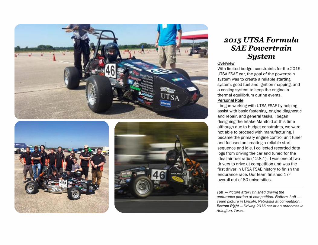
2015 UTSA Formula SAE Powertrain
SystemOverview
With limited budget constraints for the 2015
UTSA FSAE car, the goal of the powertrain
system was to create a reliable starting
system, good fuel and ignition mapping, and
a cooling system to keep the engine in
thermal equilibrium during events.
Personal Role
I began working with UTSA FSAE by helping
assist with basic fastening, engine diagnostic
and repair, and general tasks. I began
designing the Intake Manifold at this time
although due to budget constraints, we were
not able to proceed with manufacturing. I
became the primary engine control unit tuner
and focused on creating a reliable start
sequence and idle. I collected recorded data
logs from driving the car and tuned for the
ideal air-fuel ratio (12.8:1). I was one of two
drivers to drive at competition and was the
first driver in UTSA FSAE history to finish the
endurance race. Our team finished 17th
overall out of 80 universities.
Top — Picture after I finished driving the
endurance portion at competition. Bottom Left —
Team picture in Lincoln, Nebraska at competition.
Bottom Right — Driving 2015 car at an autocross in
Arlington, Texas.
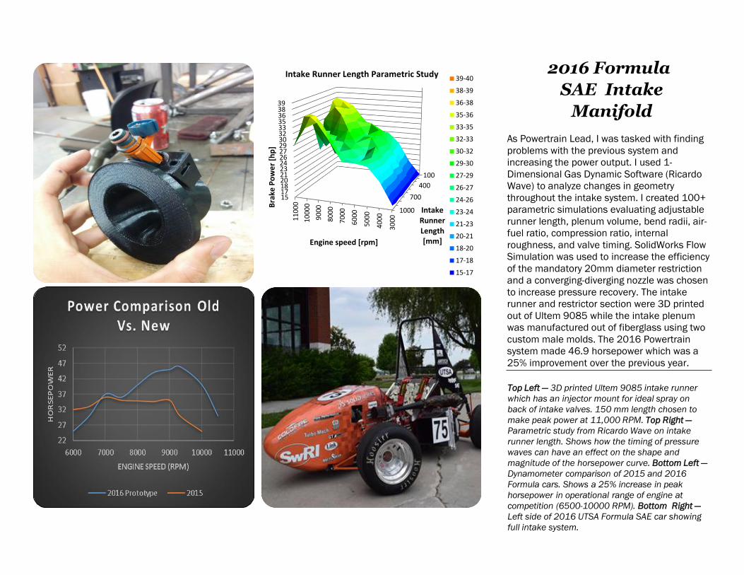
2016 Formula
SAE Intake
Manifold
As Powertrain Lead, I was tasked with finding
problems with the previous system and
increasing the power output. I used 1-
Dimensional Gas Dynamic Software (Ricardo
Wave) to analyze changes in geometry
throughout the intake system. I created 100+
parametric simulations evaluating adjustable
runner length, plenum volume, bend radii, air-
fuel ratio, compression ratio, internal
roughness, and valve timing. SolidWorks Flow
Simulation was used to increase the efficiency
of the mandatory 20mm diameter restriction
and a converging-diverging nozzle was chosen
to increase pressure recovery. The intake
runner and restrictor section were 3D printed
out of Ultem 9085 while the intake plenum
was manufactured out of fiberglass using two
custom male molds. The 2016 Powertrain
system made 46.9 horsepower which was a
25% improvement over the previous year.
Top Left — 3D printed Ultem 9085 intake runner
which has an injector mount for ideal spray on
back of intake valves. 150 mm length chosen to
make peak power at 11,000 RPM. Top Right —
Parametric study from Ricardo Wave on intake
runner length. Shows how the timing of pressure
waves can have an effect on the shape and
magnitude of the horsepower curve. Bottom Left —
Dynamometer comparison of 2015 and 2016
Formula cars. Shows a 25% increase in peak
horsepower in operational range of engine at
competition (6500-10000 RPM). Bottom Right —
Left side of 2016 UTSA Formula SAE car showing
full intake system.
100
400
700
1000
1517182021232426272930323335363839
30
00
40
00
50
00
60
00
70
00
80
00
90
00
10
000
11
000
Intake Runner Length [mm]
Bra
ke P
ow
er
[hp
]
Engine speed [rpm]
Intake Runner Length Parametric Study 39-40
38-39
36-38
35-36
33-35
32-33
30-32
29-30
27-29
26-27
24-26
23-24
21-23
20-21
18-20
17-18
15-17

2016 Formula
SAE Exhaust
Manifold
During previous years, UTSA has had
difficulties in meeting sound requirements
with single cylinder engines. I was tasked to
create an exhaust that met sound
requirements while minimizing back-
pressure. I used Helmholtz resonator theory
as a way to target the engine’s fundamental
frequencies. Once the resonators were
designed, I imported them into 1-
Dimensional Gas Dynamic Software (Ricardo
Wave) to measure estimated sound level. I
created a prototype exhaust to verify the
analytical results of the software. Once
validated, our team manufactured the
exhaust which met the stringent sound
requirements of the Formula SAE
competition.
Top Left — Initial SolidWorks concept of exhaust
using two Helmholtz resonators and a straight-
through muffler. Top Right — Proof of concept
design for testing the attenuation and precision of
Helmholtz resonators. Bottom Left — 2016 UTSA
Formula SAE car which finished 30th at competition
in Lincoln, Nebraska. Bottom Right — 2016
exhaust manifold housing three Helmholtz
resonators and two straight-through mufflers. This
exhaust design met the sound requirements at
competition.
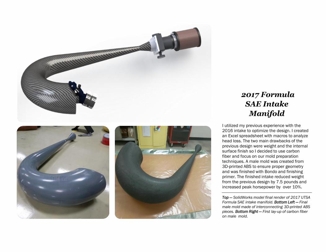
2017 Formula
SAE Intake
Manifold
I utilized my previous experience with the
2016 intake to optimize the design. I created
an Excel spreadsheet with macros to analyze
head loss. The two main drawbacks of the
previous design were weight and the internal
surface finish so I decided to use carbon
fiber and focus on our mold preparation
techniques. A male mold was created from
3D-printed ABS to ensure proper geometry
and was finished with Bondo and finishing
primer. The finished intake reduced weight
from the previous design by 7.5 pounds and
increased peak horsepower by over 10%.
Top — SolidWorks model final render of 2017 UTSA
Formula SAE intake manifold. Bottom Left — Final
male mold made of interconnecting 3D-printed ABS
pieces. Bottom Right — First lay-up of carbon fiber
on male mold.
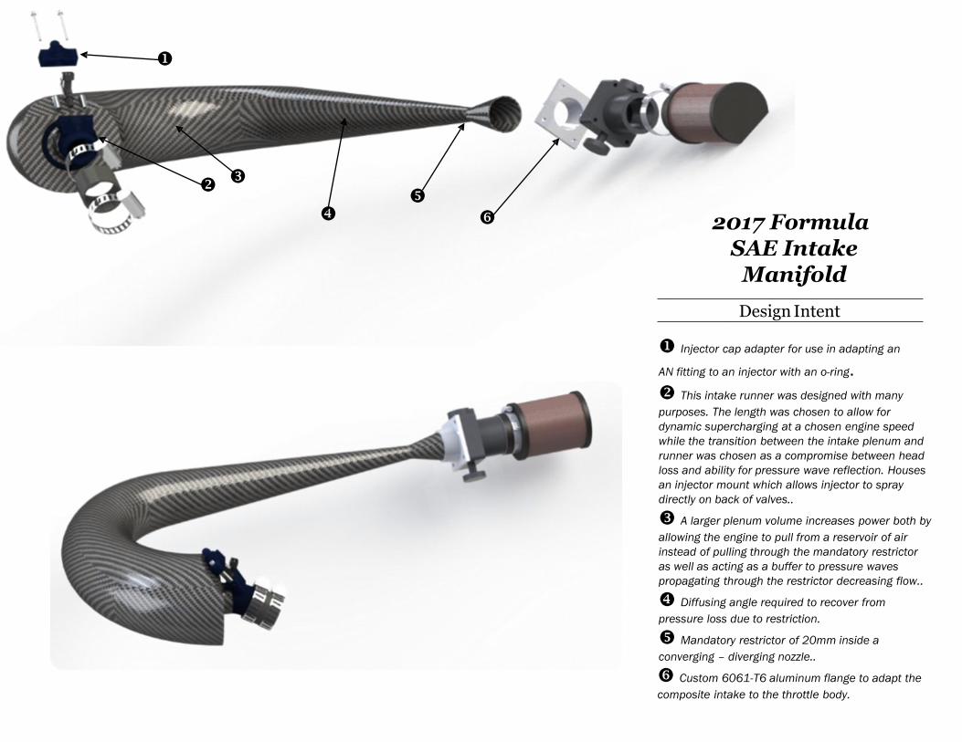
2017 FormulaSAE Intake
Manifold
Design Intent
Injector cap adapter for use in adapting an
AN fitting to an injector with an o-ring. This intake runner was designed with many
purposes. The length was chosen to allow for
dynamic supercharging at a chosen engine speed
while the transition between the intake plenum and
runner was chosen as a compromise between head
loss and ability for pressure wave reflection. Houses
an injector mount which allows injector to spray
directly on back of valves..
A larger plenum volume increases power both by
allowing the engine to pull from a reservoir of air
instead of pulling through the mandatory restrictor
as well as acting as a buffer to pressure waves
propagating through the restrictor decreasing flow..
Diffusing angle required to recover from
pressure loss due to restriction.
Mandatory restrictor of 20mm inside a
converging – diverging nozzle..
Custom 6061-T6 aluminum flange to adapt the
composite intake to the throttle body.

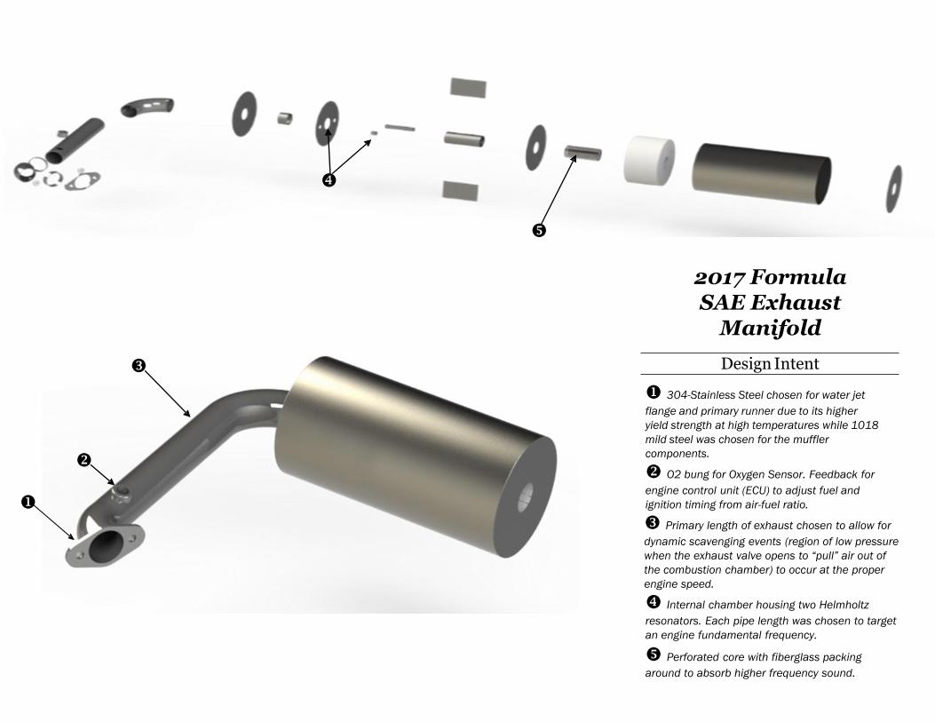
2017 Formula
SAE Exhaust
Manifold
The purpose of this project was to create a
lightweight exhaust which could meet the
stringent sound requirements by Formula
SAE while minimizing back pressure. I utilized
previous experience with exhaust design and
incorporated two Helmholtz chambers inside
to target two fundamental engine
frequencies. Exhaust primary length was
chosen to allow for dynamic scavenging.
(Allowing for the exhaust valves to have a
region of low pressure when they open to
“pull” air out of the combustion chamber)
Top — Final render of exhaust manifold assembly
for 2017 UTSA Formula SAE car. Bottom Left —
Senior design group which focused on the entire
Powertrain system. Bottom Right — Exhaust
manifold manufactured with both 304 stainless
steel and 1018 mild steel. Exhaust was back-
purged with Argon to avoid weld penetration on
the inside surface to minimize head loss.
2017 Formula SAE Exhaust
Manifold
Design Intent
304-Stainless Steel chosen for water jet
flange and primary runner due to its higher
yield strength at high temperatures while 1018
mild steel was chosen for the muffler
components.
O2 bung for Oxygen Sensor. Feedback for
engine control unit (ECU) to adjust fuel and
ignition timing from air-fuel ratio.
Primary length of exhaust chosen to allow for
dynamic scavenging events (region of low pressure
when the exhaust valve opens to “pull” air out of
the combustion chamber) to occur at the proper
engine speed.
Internal chamber housing two Helmholtz
resonators. Each pipe length was chosen to target
an engine fundamental frequency.
Perforated core with fiberglass packing
around to absorb higher frequency sound.
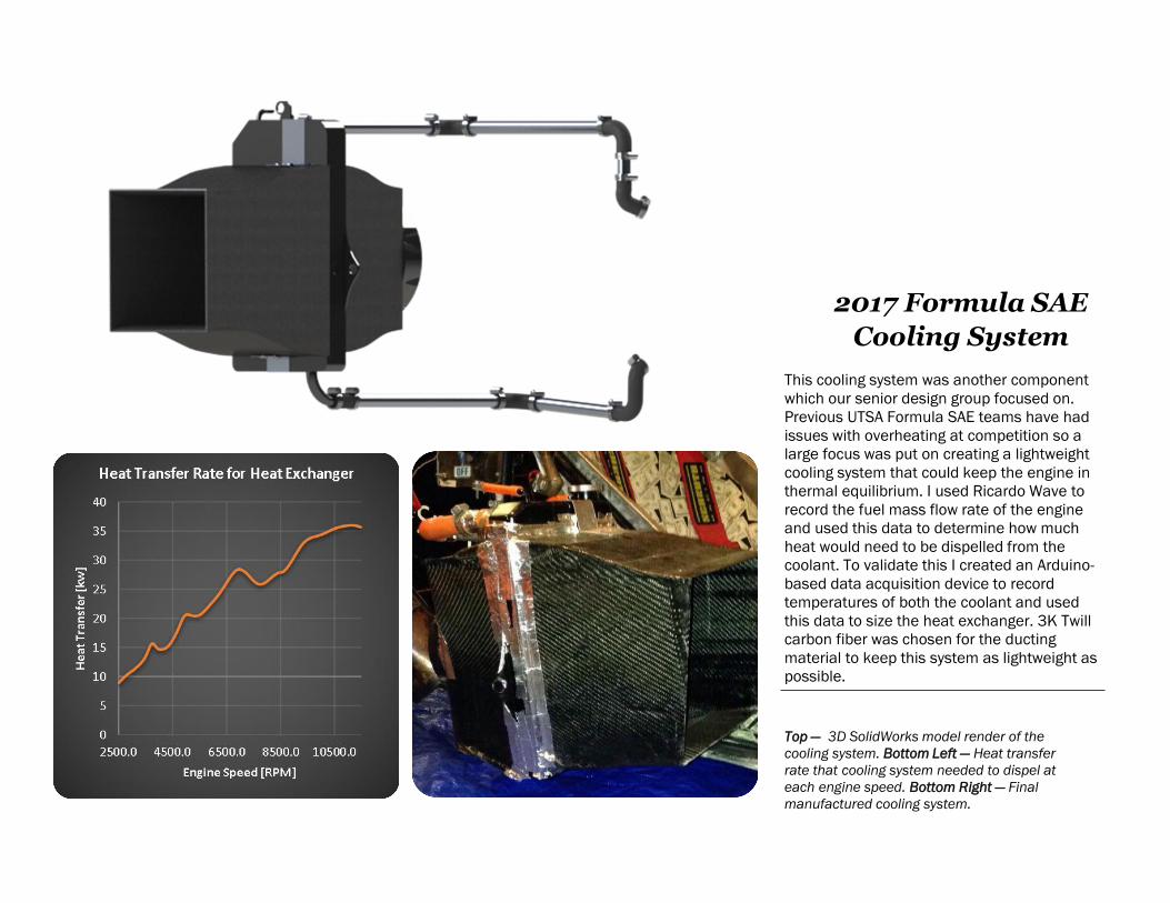
2017 Formula SAE
Cooling System
This cooling system was another component
which our senior design group focused on.
Previous UTSA Formula SAE teams have had
issues with overheating at competition so a
large focus was put on creating a lightweight
cooling system that could keep the engine in
thermal equilibrium. I used Ricardo Wave to
record the fuel mass flow rate of the engine
and used this data to determine how much
heat would need to be dispelled from the
coolant. To validate this I created an Arduino-
based data acquisition device to record
temperatures of both the coolant and used
this data to size the heat exchanger. 3K Twill
carbon fiber was chosen for the ducting
material to keep this system as lightweight as
possible.
Top — 3D SolidWorks model render of the
cooling system. Bottom Left — Heat transfer
rate that cooling system needed to dispel at
each engine speed. Bottom Right — Final
manufactured cooling system.

Diverging nozzle design allows for a high pressure region on the front of the heat exchanger to create a greater mass
flow rate and a greater heat transfer rate as a result. Manufactured with 3K Twill carbon fiber for its lightweight and ease of
manufacture.
Heat exchanger area chosen through Effectiveness-NTU method and through simulation in Ricardo Wave.
Converging nozzle design works in consort with the front diverging design to generate the greatest pressure differential.
Mounting created for fan to rivet on and ensure that all air must pass through the fan..
6061-T6 aluminum mounts were created to rivet onto carbon fiber radiator ducts to ensure positioning if car impacted a
cone.
High-flow fan was chosen to achieve the desirable volumetric flow rate while minimizing amp draw on the electrical
system.
6061-T6 aluminum tube was used due it being lighter than silicone couplers as well as its ability to transfer a small
amount of heat out of the coolant..
2017 Formula SAE Cooling System
Design Intent