Embed Size (px)
Citation preview

DENTAL UNIT
OPERATING INSTRUCTIONS
Thank you for purchasing TAKARA BELMONT product. Please read through this instruction manual carefully before using the product
to ensure proper use. Failure to read the instruction manual before use may lead to an accident.
After the installation has been completed, keep this instruction manual near the product for future maintenance. Refer this manual as needed.
If you have any questions about this Manual or this product, please contact us. If manual becomes unreadable or is lost, please request a new manual by contacting your dealer.
Installation should be conducted by authorized personnel only. Follow instructions on installation manual.
H
BOOK NO. 1E03D2C0 (3E)Printed in JAPAN. 2014-07

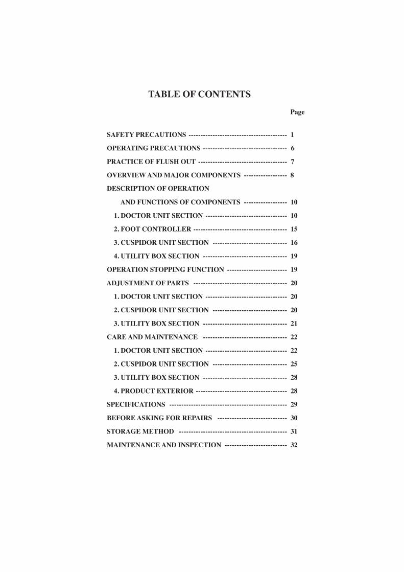
TABLE OF CONTENTS
Page SAFETY PRECAUTIONS ----------------------------------------- 1
OPERATING PRECAUTIONS ----------------------------------- 6
PRACTICE OF FLUSH OUT ------------------------------------- 7
OVERVIEW AND MAJOR COMPONENTS ------------------ 8
DESCRIPTION OF OPERATION
AND FUNCTIONS OF COMPONENTS ------------------ 10
1. DOCTOR UNIT SECTION ---------------------------------- 10
2. FOOT CONTROLLER --------------------------------------- 15
3. CUSPIDOR UNIT SECTION ------------------------------- 16
4. UTILITY BOX SECTION ----------------------------------- 19
OPERATION STOPPING FUNCTION ------------------------- 19
ADJUSTMENT OF PARTS --------------------------------------- 20
1. DOCTOR UNIT SECTION ---------------------------------- 20
2. CUSPIDOR UNIT SECTION ------------------------------- 20
3. UTILITY BOX SECTION ----------------------------------- 21
CARE AND MAINTENANCE ----------------------------------- 22
1. DOCTOR UNIT SECTION ---------------------------------- 22
2. CUSPIDOR UNIT SECTION ------------------------------- 25
3. UTILITY BOX SECTION ----------------------------------- 28
4. PRODUCT EXTERIOR -------------------------------------- 28
SPECIFICATIONS ------------------------------------------------- 29
BEFORE ASKING FOR REPAIRS ----------------------------- 30
STORAGE METHOD --------------------------------------------- 31
MAINTENANCE AND INSPECTION -------------------------- 32

Intended Use of the Product
This product is an active therapeutic device intended for the exclusive use for diagnoses,
treatments and relative procedures of dentistry.
The product must be operated or handled by the qualified dentists or by dental staffs under the supervision of the dentist. Such dentists or dental staffs should instruct and/or assist the patients to approach to and leave from the product. Patients should not be allowed to operate or handle the product unless he/she is so instructed. The product is supplied together with the handpieces like air turbine and/or motor, scaler and so on.
In case of disposal of equipment In case of disposal o equipment or of components dismounted from the unit, take full infection
preventing measures, and carry out appropriate steps in accordance with the legal regulations at that
time.
Disposal of residue material
Please request a special contractor when you dispose amalgam.
Important Notes In case of the troubles, please contact Takara Belmont offices or your dealers.
Do not disassemble or attempt to repair.
Disassembly, repair or modifications should only be done by a qualified repair technician.
Attempts at disassembly, repair or modifications may lead to abnormal operation and accidents.
SYMBOLS
In this manual, on the labels, on the control panel of Clesta eIII, following symbols are used. Confirm the meaning of each symbol.
Chair last position Chair auto return Chair preset1 Chair preset2
To lower the chair
Syringe
Dental lightselect switch
Service outlet (water)
Service outlet (air) Water heater
AirType B Applied Parts
CautionIt means “caution, warnings, or possibility to danger”.
To Recline the backrest
To raise the backrest
Chair manual control
Water
Bowl flush Cupfiller
Protective earth (ground) ON (power) OFF (power)
To raise the chair
Alternating current
Autoclave SymbolThis symbol on component means that the component can be sterilised with an autoclave at 135℃ max.
Refer to operating instructions
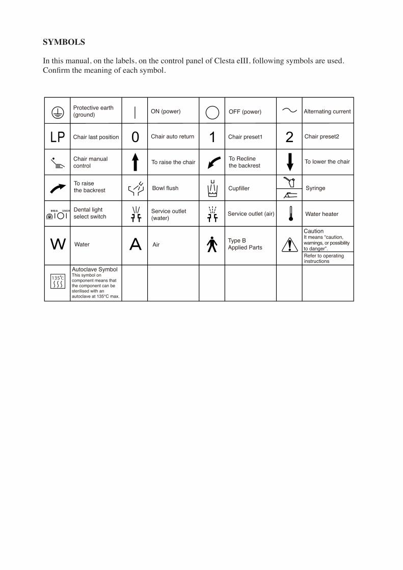
SAFETY PRECAUTIONS
Before use, read the “Safety precautions” carefully to ensure proper use.
The following information is designed to ensure safe use of this product and to prevent injury and damage
to you and others. The precautions contained here are classified depending on the severity and degree of
imminence of possible injury or damage resulting from improper use. Be sure to follow all the
information, which is important for safety.
This symbol indicates that “it is recommended to follow these precautionsfor safety.”
Classification of precautions Severity and degree of imminence of possible injury or damage
WARNING
CAUTION
NOTICE
This symbol indicates that “ignorance of these precautions may lead to severeinjury or even death as a result of improper use.”
This symbol indicates that “ignorance of these precautions may lead to mildor moderate physical injury or damage to property as a result of improper use.”
WARNING
Be sure to turn off breakers for equipment in the clinic when this product will not be used for a long period of time (following the completion of work, during the suspension of business, etc.). Insulation degradation may cause electrical fire.
1. Be sure to turn off breakers for equipment in the clinic when this product will not be used for a long period of time
2. Be sure to turn off the main switch upon completion of work or during work breaks
Be sure to turn off the main switch upon completion of work or during work breaks. This prevents incorrect operation due to accidental contact and associated hazards.
6. Never disassemble, repair or modify this product
Individuals other than certified repair technicians should not disassemble or attempt to repair and modify this product. This could lead to an accident, failure, electric shock or fire.
5. Be sure to establish a grounding connection
Be sure to establish a proper grounding connection. (Refer to a vendor for grounding connection.) Failure or electric leakage may lead to electric shock.
7. Use with caution in the presence of electromagnetic interference waves
Do not place this product around equipment generating electromagnetic waves (including communications equipment, elevators, etc.) as incorrect operation of this product may occur in the presence of electromagnetic interference waves. Do not use equipment generating electromagnetic waves, such as mobile phones, around this product.
3. Do not sit on other than seat
When the backrest is at the forward position. do not sit on or place an undue load on the headrest or legrest of dental chair. This could cause the unit to topple or could damage the unit.
4. Do not place an undue load on the arm
Do not get on or place an undue load on the arm of this unit or dental chair armrest. This could cause the unit to topple or other accidents.
- 1 -
- 1 - - 2 -
WARNING
CAUTION
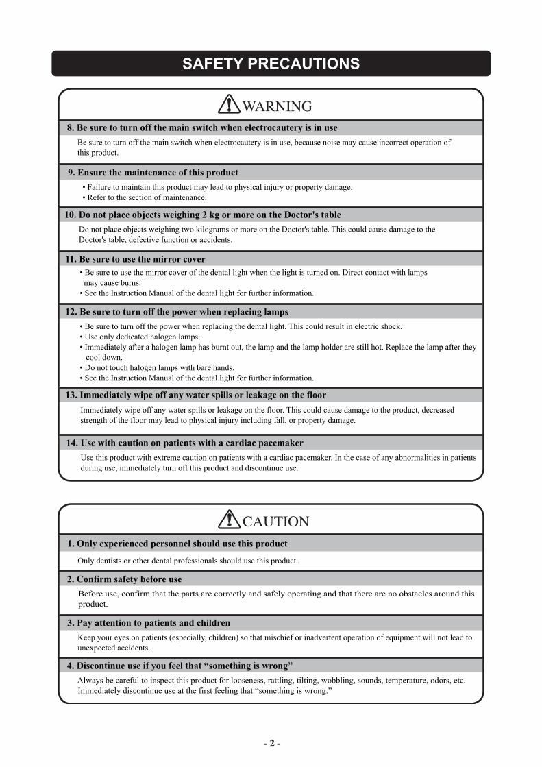
8. Be sure to turn off the main switch when electrocautery is in use
Be sure to turn off the main switch when electrocautery is in use, because noise may cause incorrect operation of this product.
14. Use with caution on patients with a cardiac pacemaker
Use this product with extreme caution on patients with a cardiac pacemaker. In the case of any abnormalities in patients during use, immediately turn off this product and discontinue use.
9. Ensure the maintenance of this product
• Failure to maintain this product may lead to physical injury or property damage. • Refer to the section of maintenance.
11. Be sure to use the mirror cover • Be sure to use the mirror cover of the dental light when the light is turned on. Direct contact with lamps may cause burns. • See the Instruction Manual of the dental light for further information.
12. Be sure to turn off the power when replacing lamps
• Be sure to turn off the power when replacing the dental light. This could result in electric shock. • Use only dedicated halogen lamps. • Immediately after a halogen lamp has burnt out, the lamp and the lamp holder are still hot. Replace the lamp after they cool down. • Do not touch halogen lamps with bare hands. • See the Instruction Manual of the dental light for further information.
10. Do not place objects weighing 2 kg or more on the Doctor's table
Do not place objects weighing two kilograms or more on the Doctor's table. This could cause damage to the Doctor's table, defective function or accidents.
1. Only experienced personnel should use this product
Only dentists or other dental professionals should use this product.
2. Confirm safety before use
Before use, confirm that the parts are correctly and safely operating and that there are no obstacles around this product.
3. Pay attention to patients and children
Keep your eyes on patients (especially, children) so that mischief or inadvertent operation of equipment will not lead to unexpected accidents.
4. Discontinue use if you feel that “something is wrong”
Always be careful to inspect this product for looseness, rattling, tilting, wobbling, sounds, temperature, odors, etc. Immediately discontinue use at the first feeling that “something is wrong.”
13. Immediately wipe off any water spills or leakage on the floor
Immediately wipe off any water spills or leakage on the floor. This could cause damage to the product, decreased strength of the floor may lead to physical injury including fall, or property damage.
SAFETY PRECAUTIONS
- 3 -
SAFETY PRECAUTIONS
CAUTION
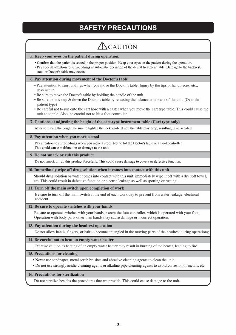
11. Turn off the main switch upon completion of work Be sure to turn off the main switch at the end of each work day to prevent from water leakage, electrical accident.
5. Keep your eyes on the patient during operation. • Confirm that the patient is seated in the proper position. Keep your eyes on the patient during the operation. • Pay special attention to surroundings at automatic operation of the dental treatment table. Damage to the backrest, stool or Doctor's table may occur.
6. Pay attention during movement of the Doctor's table • Pay attention to surroundings when you move the Doctor's table. Injury by the tips of handpieces, etc., may occur. • Be sure to move the Doctor's table by holding the handle of the unit. • Be sure to move up & down the Doctor's table by releasing the balance arm brake of the unit. (Over the patient type) • Be careful not to run onto the cart hose with a caster when you move the cart type table. This could cause the unit to topple. Also, be careful not to hit a foot controller.
10. Immediately wipe off drug solution when it comes into contact with this unit Should drug solution or water comes into contact with this unit, immediately wipe it off with a dry soft towel, etc. This could result in defective function or electric leakage as well as spotting or rusting.
12. Be sure to operate switches with your hands Be sure to operate switches with your hands, except the foot controller, which is operated with your foot. Operation with body parts other than hands may cause damage or incorrect operation.
13. Pay attention during the headrest operation Do not allow hands, fingers, or hair to become entangled in the moving parts of the headrest during operationg.
9. Do not smack or rub this product Do not smack or rub this product forcefully. This could cause damage to covers or defective function.
14. Be careful not to heat an empty water heater Exercise caution as heating of an empty water heater may result in burning of the heater, leading to fire.
16. Precautions for sterilization Do not sterilize besides the procedures that we provide. This could cause damage to the unit.
7. Cautions at adjusting the height of the cart-type instrument table (Cart type only) After adjusting the height, be sure to tighten the lock knob. If not, the table may drop, resulting in an accident
8. Pay attention when you move a stool Pay attention to surroundings when you move a stool. Not to hit the Doctor's table or a Foot controller. This could cause malfunction or damage to the unit.
15. Precautions for cleaning • Never use sandpaper, metal scrub brushes and abrasive cleaning agents to clean the unit. • Do not use strongly acidic cleaning agents or alkaline pipe cleaning agents to avoid corrosion of metals, etc.
- 3 - - 4 -
SAFETY PRECAUTIONS
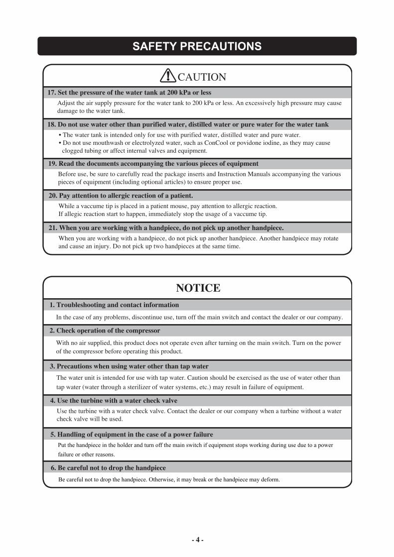
CAUTION17. Set the pressure of the water tank at 200 kPa or less Adjust the air supply pressure for the water tank to 200 kPa or less. An excessively high pressure may cause damage to the water tank.
19. Read the documents accompanying the various pieces of equipment Before use, be sure to carefully read the package inserts and Instruction Manuals accompanying the various pieces of equipment (including optional articles) to ensure proper use.
18. Do not use water other than purified water, distilled water or pure water for the water tank • The water tank is intended only for use with purified water, distilled water and pure water. • Do not use mouthwash or electrolyzed water, such as ConCool or povidone iodine, as they may cause clogged tubing or affect internal valves and equipment.
5. Handling of equipment in the case of a power failure Put the handpiece in the holder and turn off the main switch if equipment stops working during use due to a power
failure or other reasons.
NOTICE1. Troubleshooting and contact information
In the case of any problems, discontinue use, turn off the main switch and contact the dealer or our company.
2. Check operation of the compressor
With no air supplied, this product does not operate even after turning on the main switch. Turn on the power of the compressor before operating this product.
4. Use the turbine with a water check valve Use the turbine with a water check valve. Contact the dealer or our company when a turbine without a water check valve will be used.
3. Precautions when using water other than tap water The water unit is intended for use with tap water. Caution should be exercised as the use of water other than tap water (water through a sterilizer of water systems, etc.) may result in failure of equipment.
Be careful not to drop the handpiece. Otherwise, it may break or the handpiece may deform.
6. Be careful not to drop the handpiece
20. Pay attention to allergic reaction of a patient. While a vaccume tip is placed in a patient mouse, pay attention to allergic reaction. If allegic reaction start to happen, immediately stop the usage of a vaccume tip.
21. When you are working with a handpiece, do not pick up another handpiece. When you are working with a handpiece, do not pick up another handpiece. Another handpiece may rotate and cause an injury. Do not pick up two handpieces at the same time.
SAFETY PRECAUTIONS
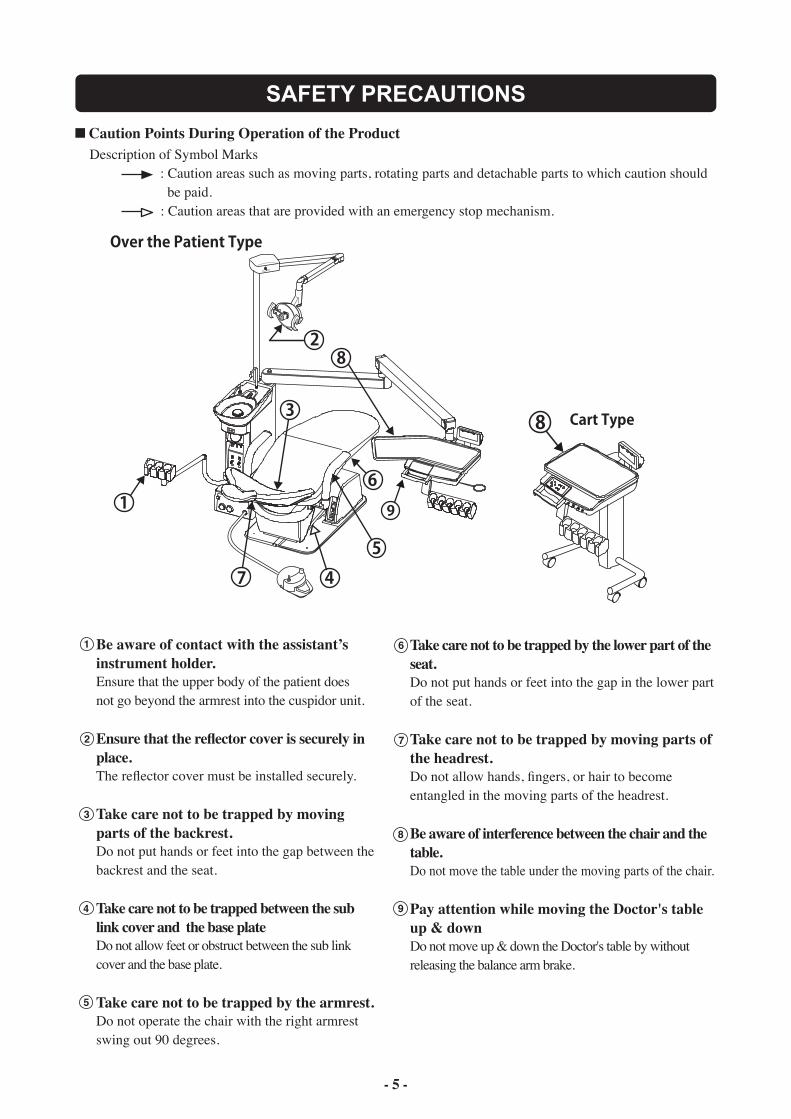
Caution Points During Operation of the Product Description of Symbol Marks : Caution areas such as moving parts, rotating parts and detachable parts to which caution should be paid. : Caution areas that are provided with an emergency stop mechanism.
- 5 -
Be aware of contact with the assistant’s instrument holder.Ensure that the upper body of the patient doesnot go beyond the armrest into the cuspidor unit.
Ensure that the reflector cover is securely in place.The reflector cover must be installed securely.
Take care not to be trapped by moving parts of the backrest.Do not put hands or feet into the gap between the backrest and the seat.
Take care not to be trapped between the sub link cover and the base plateDo not allow feet or obstruct between the sub link cover and the base plate.
Take care not to be trapped by the armrest.Do not operate the chair with the right armrest swing out 90 degrees.
1
2
3
4
5
Take care not to be trapped by the lower part of the seat.Do not put hands or feet into the gap in the lower part of the seat.
Take care not to be trapped by moving parts of the headrest.Do not allow hands, fingers, or hair to become entangled in the moving parts of the headrest.
Be aware of interference between the chair and the table.Do not move the table under the moving parts of the chair.
Pay attention while moving the Doctor's table up & downDo not move up & down the Doctor's table by withoutreleasing the balance arm brake.
6
7
8
9
H
OPERATING PRECAUTIONS
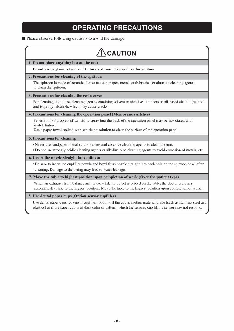
Please observe following cautions to avoid the damage.
CAUTION1. Do not place anything hot on the unit Do not place anything hot on the unit. This could cause deformation or discoloration.
2. Precautions for cleaning of the spittoon The spittoon is made of ceramic. Never use sandpaper, metal scrub brushes or abrasive cleaning agents to clean the spittoon.
3. Precautions for cleaning the resin cover For cleaning, do not use cleaning agents containing solvent or abrasives, thinners or oil-based alcohol (butanol and isopropyl alcohol), which may cause cracks.
4. Precautions for cleaning the operation panel (Membrane switches) Penetration of droplets of sanitizing spray into the back of the operation panel may be associated with switch failure. Use a paper towel soaked with sanitizing solution to clean the surface of the operation panel.
5. Precautions for cleaning • Never use sandpaper, metal scrub brushes and abrasive cleaning agents to clean the unit. • Do not use strongly acidic cleaning agents or alkaline pipe cleaning agents to avoid corrosion of metals, etc.
6. Insert the nozzle straight into spittoon • Be sure to insert the cupfiller nozzle and bowl flush nozzle straight into each hole on the spittoon bowl after cleaning. Damage to the o-ring may lead to water leakege.
8. Use dental paper cups (Option sensor cupfiller)Use dental paper cups for sensor cupfiller (option). If the cup is another material grade (such as stainless steel andplastics) or if the paper cup is of dark color or pattern, which the sensing cup filling sensor may not respond.
7. Move the table to highest position upon completion of work (Over the patient type) When air exhausts from balance arm brake while no object is placed on the table, the doctor table may automatically raise to the highest position. Move the table to the highest position upon completion of work.
- 6 -
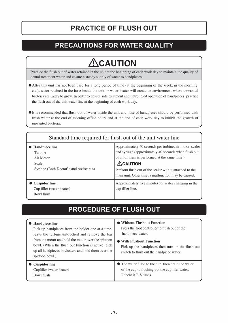
PRECAUTIONS FOR WATER QUALITY
CAUTIONPractice the flush out of water retained in the unit at the beginning of each work day to maintain the quality of dental treatment water and ensure a steady supply of water to handpieces.
After this unit has not been used for a long period of time (at the beginning of the week, in the morning, etc.), water retained in the hose inside the unit or water heater will create an environment where unwanted bacteria are likely to grow. In order to ensure safe treatment and untroubled operation of handpieces, practice the flush out of the unit water line at the beginning of each work day.
It is recommended that flush out of water inside the unit and hose of handpieces should be performed with fresh water at the end of morning office hours and at the end of each work day to inhibit the growth of unwanted bacteria.
Handpiece line Turbine Air Motor Scaler Syringe (Both Doctor' s and Assistant's)
Cuspidor lineCup filler (water heater)Bowl flush
Approximately five minutes for water changing in the cup filler line.
Handpiece linePick up handpieces from the holder one at a time, leave the turbine untouched and remove the bar from the motor and hold the motor over the spittoon bowl. (When the flush out function is active, pick up all handpieces in clusters and hold them over the spittoon bowl.)
Cuspidor lineCupfiller (water heater)Bowl flush
Approximately 40 seconds per turbine, air motor, scaler and syringe (approximately 40 seconds when flush out of all of them is performed at the same time.)
PRACTICE OF FLUSH OUT
Standard time required for flush out of the unit water line
CAUTIONPerform flush out of the scaler with it attached to the main unit. Otherwise, a malfunction may be caused.
PROCEDURE OF FLUSH OUT
- 7 -
Without Flushout FunctionPress the foot controller to flush out of the handpiece water.
With Flushout FunctionPick up the handpieces then turn on the flush out switch to flush out the handpiece water.
The water filled to the cup, then drain the water of the cup to flushing out the cupfiller water. Repeat it 7~8 times.
- 8 -
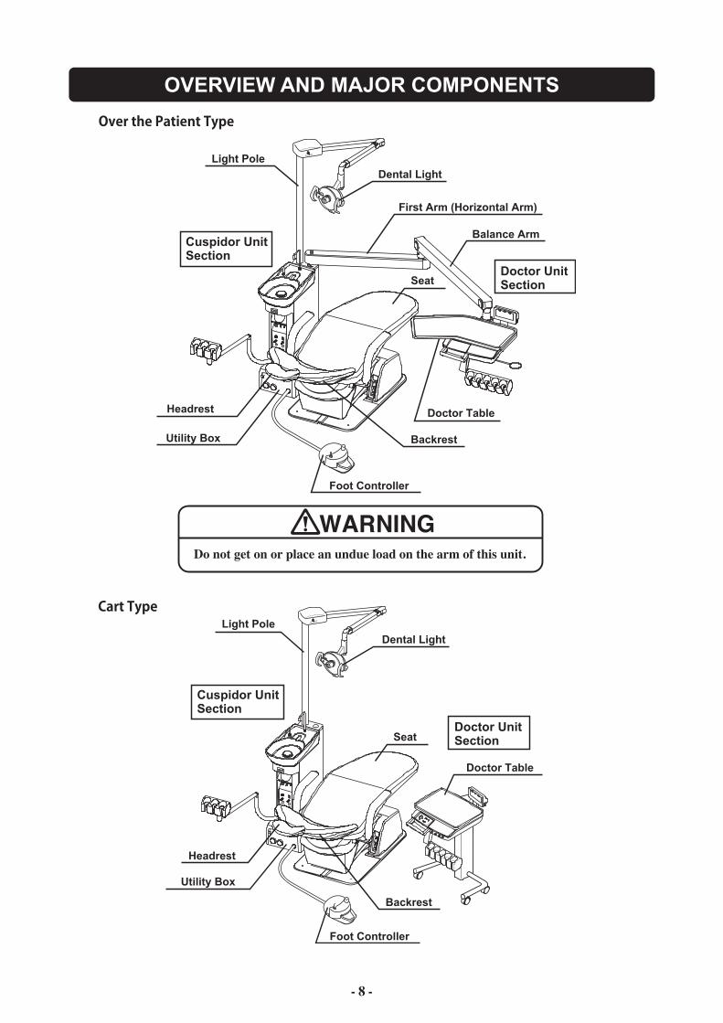
OVERVIEW AND MAJOR COMPONENTS
H
Cuspidor Unit Section
Doctor UnitSection
Doctor Table
Foot Controller
Utility Box
Dental Light
Light Pole
First Arm (Horizontal Arm)
Balance Arm
H
Light Pole
Dental Light
Cuspidor Unit Section
Doctor UnitSection
Doctor Table
Foot Controller
Utility Box
Backrest
Headrest
Seat
Seat
Headrest
Backrest
Do not get on or place an undue load on the arm of this unit.
WARNING
- 9 -
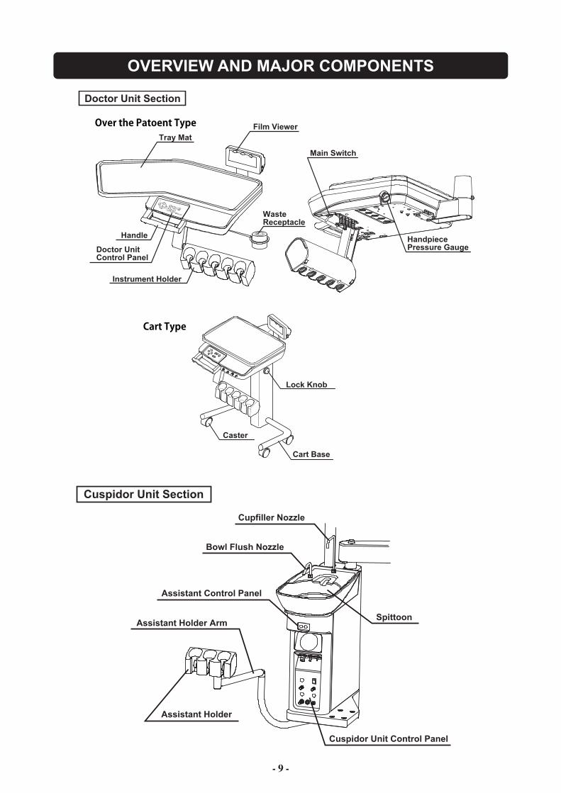
OVERVIEW AND MAJOR COMPONENTS
Doctor Unit Section
Tray MatFilm Viewer
Waste Receptacle
Instrument Holder
Handle
Doctor Unit Control Panel
Main Switch
HandpiecePressure Gauge
Caster
Cart Base
Lock Knob
Cuspidor Unit Section
Cupfiller Nozzle
Bowl Flush Nozzle
Spittoon
Cuspidor Unit Control Panel
Assistant Holder Arm
Assistant Holder
Assistant Control Panel
- 10 -
DESCRIPTION OF OPERATION AND FUNCTIONS OF COMPONENTS
Flushout Switch (optional)
Handpiece Light ON-OFF Switch (optional)
Handpiece Pressure Gauge
ON OFF
ON OFF
Main LED (Green)
Main Switch Main Switch
1 Doctor Unit Section1
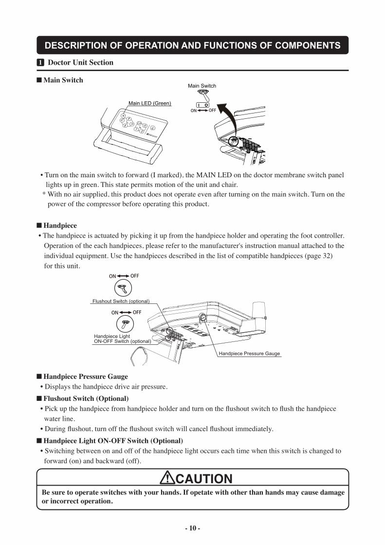
CAUTIONBe sure to operate switches with your hands. If opetate with other than hands may cause damage or incorrect operation.
Handpiece Pressure Gauge • Displays the handpiece drive air pressure.
Flushout Switch (Optional) • Pick up the handpiece from handpiece holder and turn on the flushout switch to flush the handpiece water line. • During flushout, turn off the flushout switch will cancel flushout immediately.
Handpiece Light ON-OFF Switch (Optional) • Switching between on and off of the handpiece light occurs each time when this switch is changed to forward (on) and backward (off).
• Turn on the main switch to forward (I marked), the MAIN LED on the doctor membrane switch panel lights up in green. This state permits motion of the unit and chair. * With no air supplied, this product does not operate even after turning on the main switch. Turn on the power of the compressor before operating this product.
Handpiece • The handpiece is actuated by picking it up from the handpiece holder and operating the foot controller. Operation of the each handpieces, please refer to the manufacturer's instruction manual attached to the individual equipment. Use the handpieces described in the list of compatible handpieces (page 32) for this unit.
- 11 -
DESCRIPTION OF OPERATION AND FUNCTIONS OF COMPONENTS
Set the treatment position by chairmanual switch
Keep pressing preset switch to beset for about 5 seconds
Chair Operation Switch
Cupfiller Switch
1 Doctor Unit Section1
Chair Preset Switch
Chair Auto Return Switch
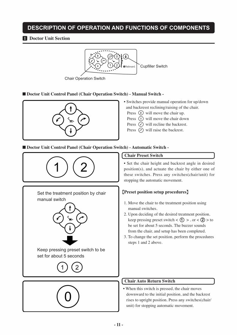
Preset position setup procedures
• Switches provide manual operation for up/down and backresst reclining/raising of the chair. Press will move the chair up. Press will move the chair down Press will recline the backrest. Press will raise the backrest.
• Set the chair height and backrest angle in desired position(s), and actuate the chair by either one of these switches. Press any switches(chair/unit) for stopping the automatic movement.
1. Move the chair to the treatment position using manual switches.2. Upon deciding of the desired treatment position, keep pressing preset switch < > , or < > to be set for about 5 seconds. The buzzer sounds from the chair, and setup has been completed.3. To change the set position, perform the procedures steps 1 and 2 above.
1 2
• When this switch is pressed, the chair moves downward to the initial position, and the backrest rises to upright position. Press any switches(chair/ unit) for stopping automatic movement.
Doctor Unit Control Panel (Chair Operation Switch) - Manual Switch -
Doctor Unit Control Panel (Chair Operation Switch) - Automatic Switch -
- 12 -
DESCRIPTION OF OPERATION AND FUNCTIONS OF COMPONENTS
Move the chair to rinsing positionby chair manual switch
Keep pressing LP for about 5 seconds
1 Doctor Unit Section1
Chair Last Position Switch
Rinsing position setup procedures
Cupfiller Switch
CAUTION
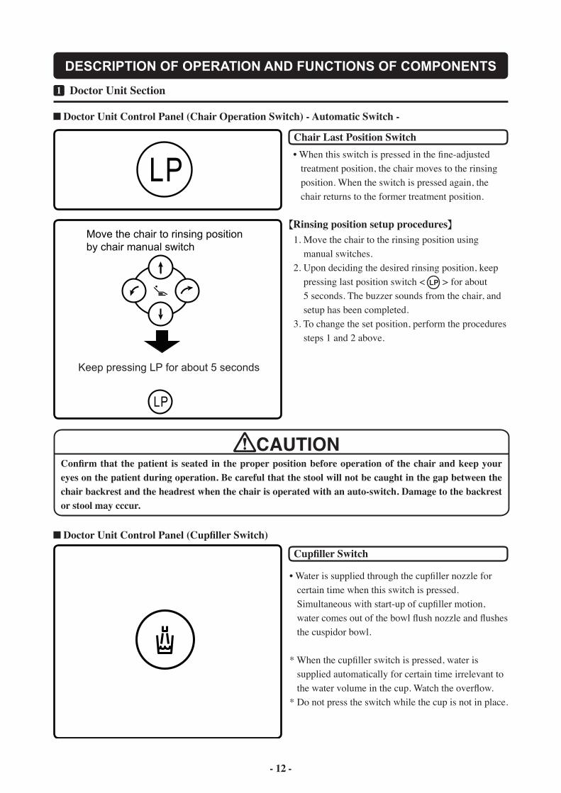
• When this switch is pressed in the fine-adjusted treatment position, the chair moves to the rinsing position. When the switch is pressed again, the chair returns to the former treatment position.
1. Move the chair to the rinsing position using manual switches.2. Upon deciding the desired rinsing position, keep pressing last position switch < > for about 5 seconds. The buzzer sounds from the chair, and setup has been completed.3. To change the set position, perform the procedures steps 1 and 2 above.
LP
Confirm that the patient is seated in the proper position before operation of the chair and keep your eyes on the patient during operation. Be careful that the stool will not be caught in the gap between the chair backrest and the headrest when the chair is operated with an auto-switch. Damage to the backrest or stool may cccur.
• Water is supplied through the cupfiller nozzle for certain time when this switch is pressed. Simultaneous with start-up of cupfiller motion, water comes out of the bowl flush nozzle and flushes the cuspidor bowl.
* When the cupfiller switch is pressed, water is supplied automatically for certain time irrelevant to the water volume in the cup. Watch the overflow.* Do not press the switch while the cup is not in place.
Doctor Unit Control Panel (Chair Operation Switch) - Automatic Switch -
Doctor Unit Control Panel (Cupfiller Switch)
- 13 -
DESCRIPTION OF OPERATION AND FUNCTIONS OF COMPONENTS
Balance Arm Air Brake button
ON-OFF Switch
Film ViewerDimmer
ON-OFF Switch
Up
Down
Lock Knob
ON
OFF
Loosen Tighten
Up
Down
Screen
Screen
1 Doctor Unit Section1
CAUTION
NOTICE
NOTICE
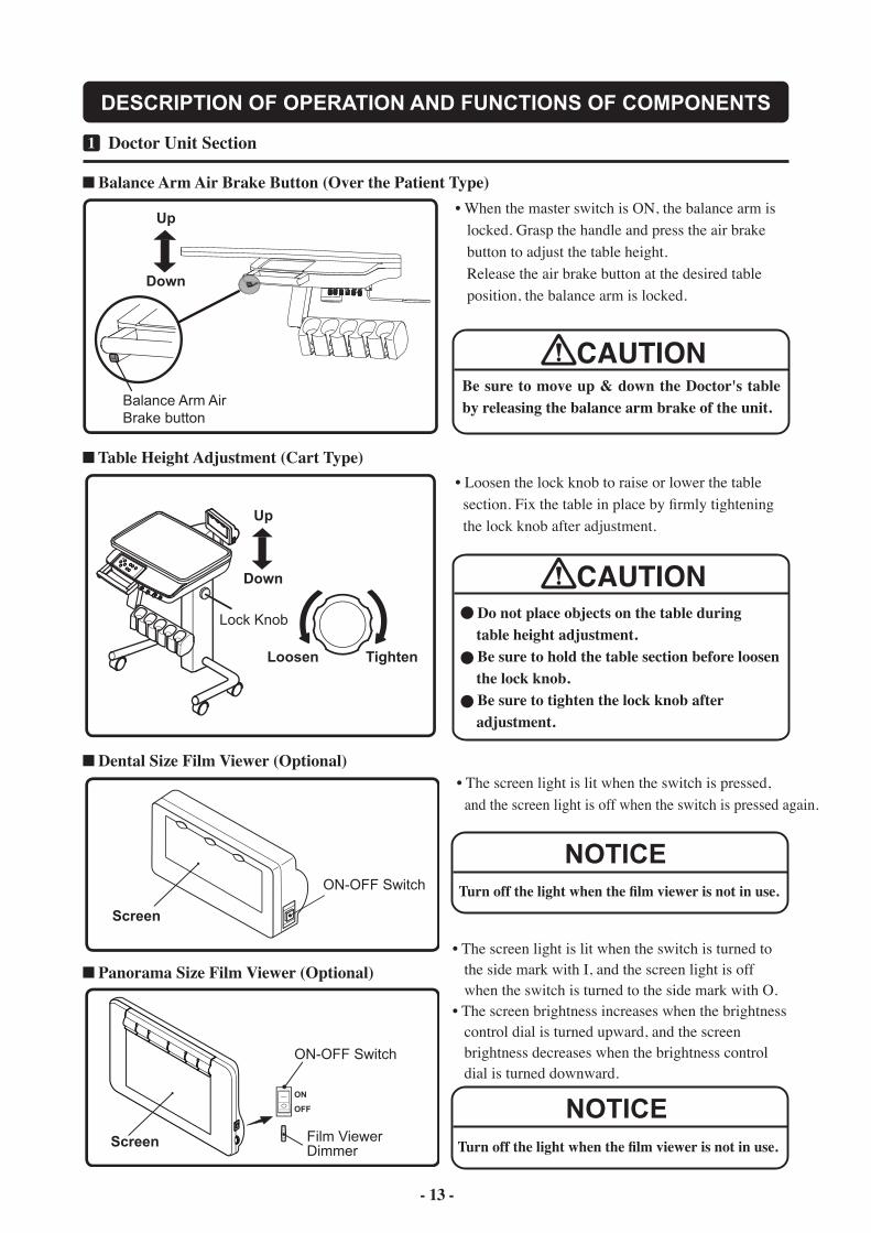
• When the master switch is ON, the balance arm is locked. Grasp the handle and press the air brake button to adjust the table height. Release the air brake button at the desired table position, the balance arm is locked.
Be sure to move up & down the Doctor's table by releasing the balance arm brake of the unit.
Turn off the light when the film viewer is not in use.
Turn off the light when the film viewer is not in use.
Balance Arm Air Brake Button (Over the Patient Type)
Dental Size Film Viewer (Optional)
Panorama Size Film Viewer (Optional)
Table Height Adjustment (Cart Type)• Loosen the lock knob to raise or lower the table section. Fix the table in place by firmly tightening the lock knob after adjustment.
Do not place objects on the table during table height adjustment.
Be sure to hold the table section before loosen the lock knob.
Be sure to tighten the lock knob after adjustment.
CAUTION
• The screen light is lit when the switch is pressed, and the screen light is off when the switch is pressed again.
• The screen light is lit when the switch is turned to the side mark with I, and the screen light is off when the switch is turned to the side mark with O.• The screen brightness increases when the brightness control dial is turned upward, and the screen brightness decreases when the brightness control dial is turned downward.
- 13 - - 14 -
DESCRIPTION OF OPERATION AND FUNCTIONS OF COMPONENTS
Scaler Power AdjustmentKnob (Optional)
Scaler E / S / PSelect Switch (Optional)
Scaler WaterAdjustment Knob (Optional)
Scaler Power AdjustmentKnob (Optional)
Scaler E / S / PSelect Switch (Optional)
* Scaler water adjustment knob (option) is located in the same position as over the patient type
ENDO SCALING PERIO
Increase Decrease
IncreaseDecrease IncreaseDecrease
1 Doctor Unit Section1
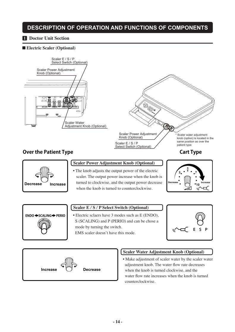
Electric Scaler (Optional)
Scaler Water Adjustment Knob (Optional)• Make adjustment of scaler water by the scaler water adjustment knob. The water flow rate decreases when the knob is turned clockwise, and the water flow rate increases when the knob is turned counterclockwise.
Scaler Power Adjustment Knob (Optional)
Scaler E / S / P Select Switch (Optional)
• The knob adjusts the output power of the electric scaler. The output power increase when the knob is turned to clockwise, and the output power decrease when the knob is turned to counterclockwise.
• Electric sclaers have 3 modes such as E (ENDO), S (SCALING) and P (PERIO) and can be chose a mode by turning the switch. EMS scaler doesn’t have this mode.
- 15 -
DESCRIPTION OF OPERATION AND FUNCTIONS OF COMPONENTS
Coolant WaterSwitch
Drive Air Pedal
Chip BlowerButton
Increase by the degree of stepping
1 Foot Controller2
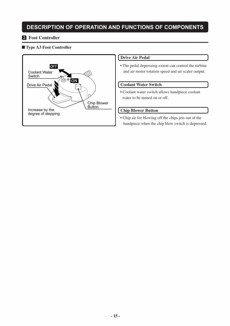
Type A3 Foot Controller
Drive Air Pedal
Coolant Water Switch
Chip Blower Button
• The pedal depressing extent can control the turbine and air motor rotation speed and air scaler output.
• Coolant water switch allows handpiece coolant water to be turned on or off.
• Chip air for blowing off the chips jets out of the handpiece when the chip blow switch is depressed.
- 15 - - 16 -
DESCRIPTION OF OPERATION AND FUNCTIONS OF COMPONENTS
Increase Decrease
1 Cuspidor Unit Section3
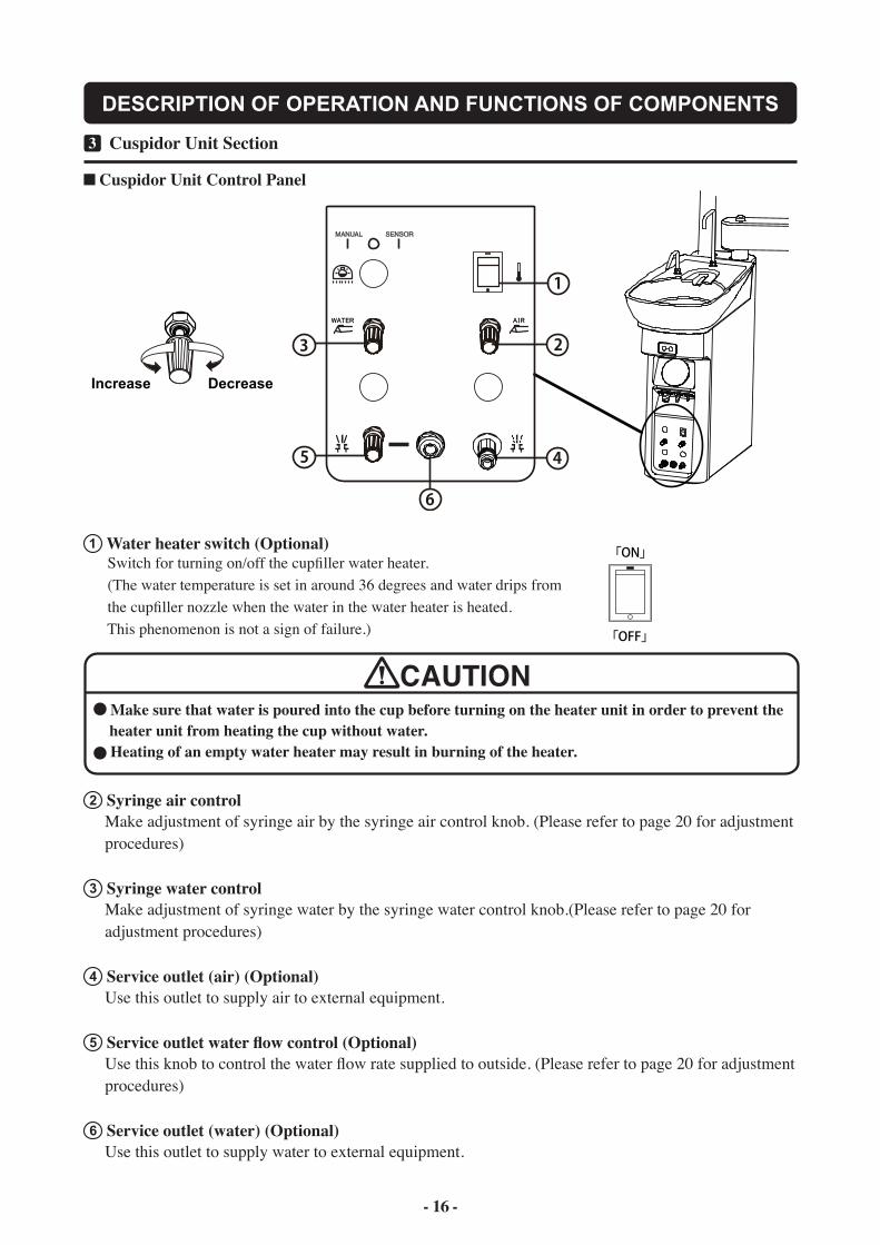
Cuspidor Unit Control Panel
1 Water heater switch (Optional) Switch for turning on/off the cupfiller water heater. (The water temperature is set in around 36 degrees and water drips from the cupfiller nozzle when the water in the water heater is heated. This phenomenon is not a sign of failure.)
CAUTION Make sure that water is poured into the cup before turning on the heater unit in order to prevent the
heater unit from heating the cup without water. Heating of an empty water heater may result in burning of the heater.
2 Syringe air control Make adjustment of syringe air by the syringe air control knob. (Please refer to page 20 for adjustment procedures)
3 Syringe water control Make adjustment of syringe water by the syringe water control knob.(Please refer to page 20 for adjustment procedures)
4 Service outlet (air) (Optional) Use this outlet to supply air to external equipment.
5 Service outlet water flow control (Optional) Use this knob to control the water flow rate supplied to outside. (Please refer to page 20 for adjustment procedures)
6 Service outlet (water) (Optional) Use this outlet to supply water to external equipment.
- 17 -
DESCRIPTION OF OPERATION AND FUNCTIONS OF COMPONENTS
Cupfiller Switch
Bowl Flush Switch
Open
Close
Slide knob
Vacuum Tip (Optional)
Slide knob
Open
Close
1 Cuspidor Unit Section3
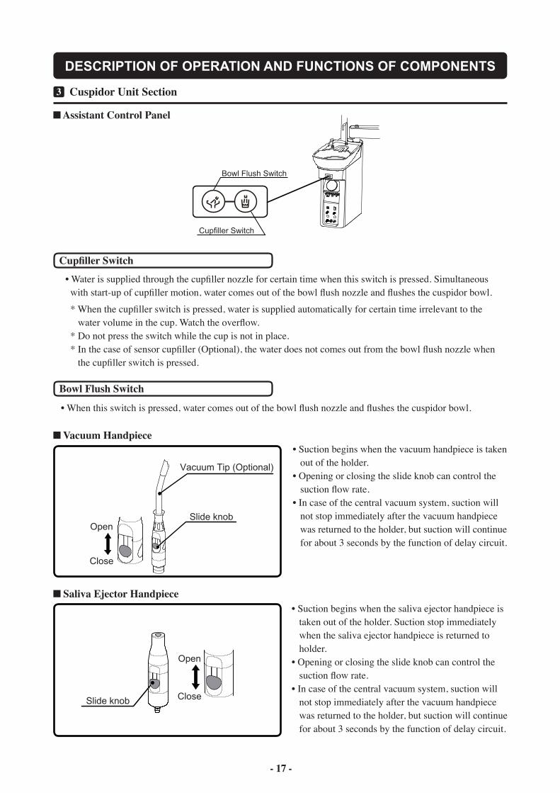
Assistant Control Panel
Cupfiller Switch
Bowl Flush Switch
• When this switch is pressed, water comes out of the bowl flush nozzle and flushes the cuspidor bowl.
Vacuum Handpiece
Saliva Ejector Handpiece
• Water is supplied through the cupfiller nozzle for certain time when this switch is pressed. Simultaneous with start-up of cupfiller motion, water comes out of the bowl flush nozzle and flushes the cuspidor bowl.
* When the cupfiller switch is pressed, water is supplied automatically for certain time irrelevant to the water volume in the cup. Watch the overflow. * Do not press the switch while the cup is not in place. * In the case of sensor cupfiller (Optional), the water does not comes out from the bowl flush nozzle when the cupfiller switch is pressed.
• Suction begins when the vacuum handpiece is taken out of the holder.• Opening or closing the slide knob can control the suction flow rate.• In case of the central vacuum system, suction will not stop immediately after the vacuum handpiece was returned to the holder, but suction will continue for about 3 seconds by the function of delay circuit.
• Suction begins when the saliva ejector handpiece is taken out of the holder. Suction stop immediately when the saliva ejector handpiece is returned to holder. • Opening or closing the slide knob can control the suction flow rate.• In case of the central vacuum system, suction will not stop immediately after the vacuum handpiece was returned to the holder, but suction will continue for about 3 seconds by the function of delay circuit.
- 17 - - 18 -
DESCRIPTION OF OPERATION AND FUNCTIONS OF COMPONENTS
OFF
ON
CITY
BOTTLE
WATER
BOTTLE
WATER
SUPPLY
WATER
BOTTLE
PRESSURE
CONTROL
Sensor Cupfiller Cupfiller Nozzle
Bowl Flush Nozzle
Spittoon BowlCup Base
Water Bottle
CITY/BOTTLE Select Switch
Pressurization ON-OFF Switch
Dental Light Mode Select Switch
AL-501 Dental Light
Water Bottle PressureControl Knob
Increase Decrease
Water Bottle PressureControl Knob
1 Cuspidor Unit Section3
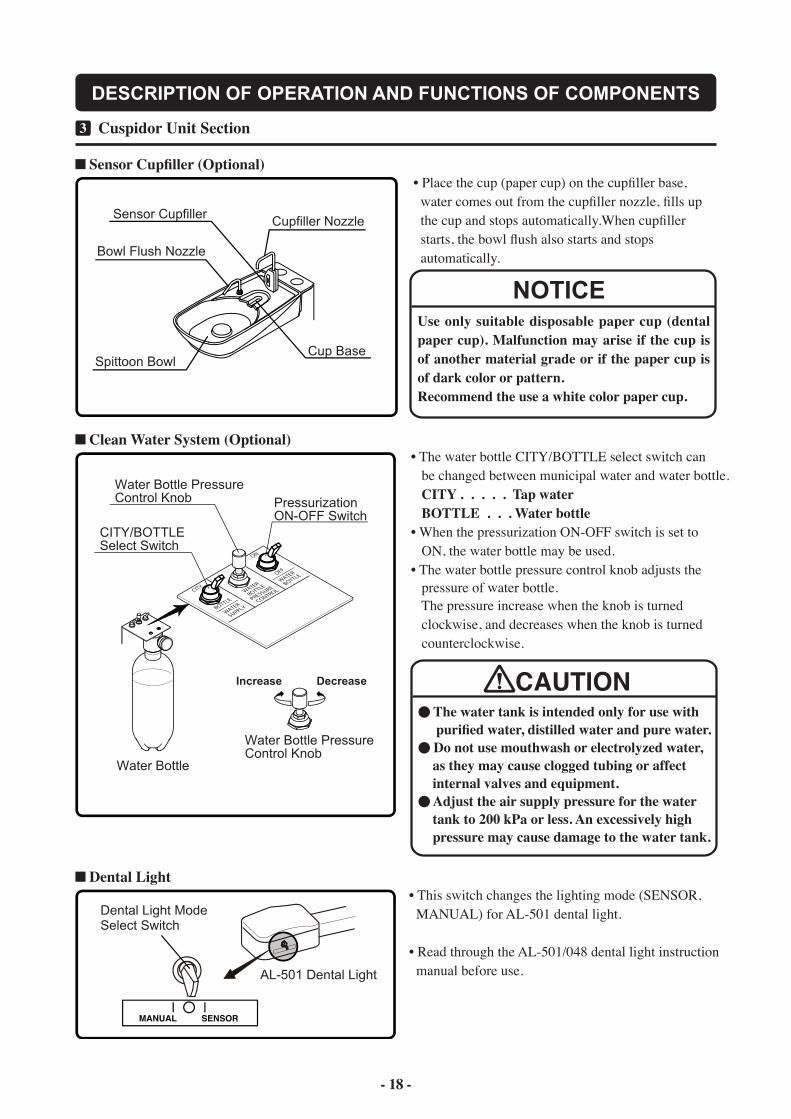
Sensor Cupfiller (Optional)
Clean Water System (Optional)
Dental Light
Use only suitable disposable paper cup (dental paper cup). Malfunction may arise if the cup is of another material grade or if the paper cup is of dark color or pattern. Recommend the use a white color paper cup.
NOTICE
• Place the cup (paper cup) on the cupfiller base, water comes out from the cupfiller nozzle, fills up the cup and stops automatically.When cupfiller starts, the bowl flush also starts and stops automatically.
• The water bottle CITY/BOTTLE select switch can be changed between municipal water and water bottle. CITY . . . . . Tap water BOTTLE . . . Water bottle• When the pressurization ON-OFF switch is set to ON, the water bottle may be used. • The water bottle pressure control knob adjusts the pressure of water bottle. The pressure increase when the knob is turned clockwise, and decreases when the knob is turned counterclockwise.
CAUTION The water tank is intended only for use with
purified water, distilled water and pure water. Do not use mouthwash or electrolyzed water,
as they may cause clogged tubing or affect internal valves and equipment.
Adjust the air supply pressure for the water tank to 200 kPa or less. An excessively high pressure may cause damage to the water tank.
• This switch changes the lighting mode (SENSOR, MANUAL) for AL-501 dental light.
• Read through the AL-501/048 dental light instruction manual before use.
- 19 -
DESCRIPTION OF OPERATION AND FUNCTIONS OF COMPONENTS
Drain Valve
Water Shut OFFValve
* In the Utility BoxAIR WATER
Air Shut OFFValve
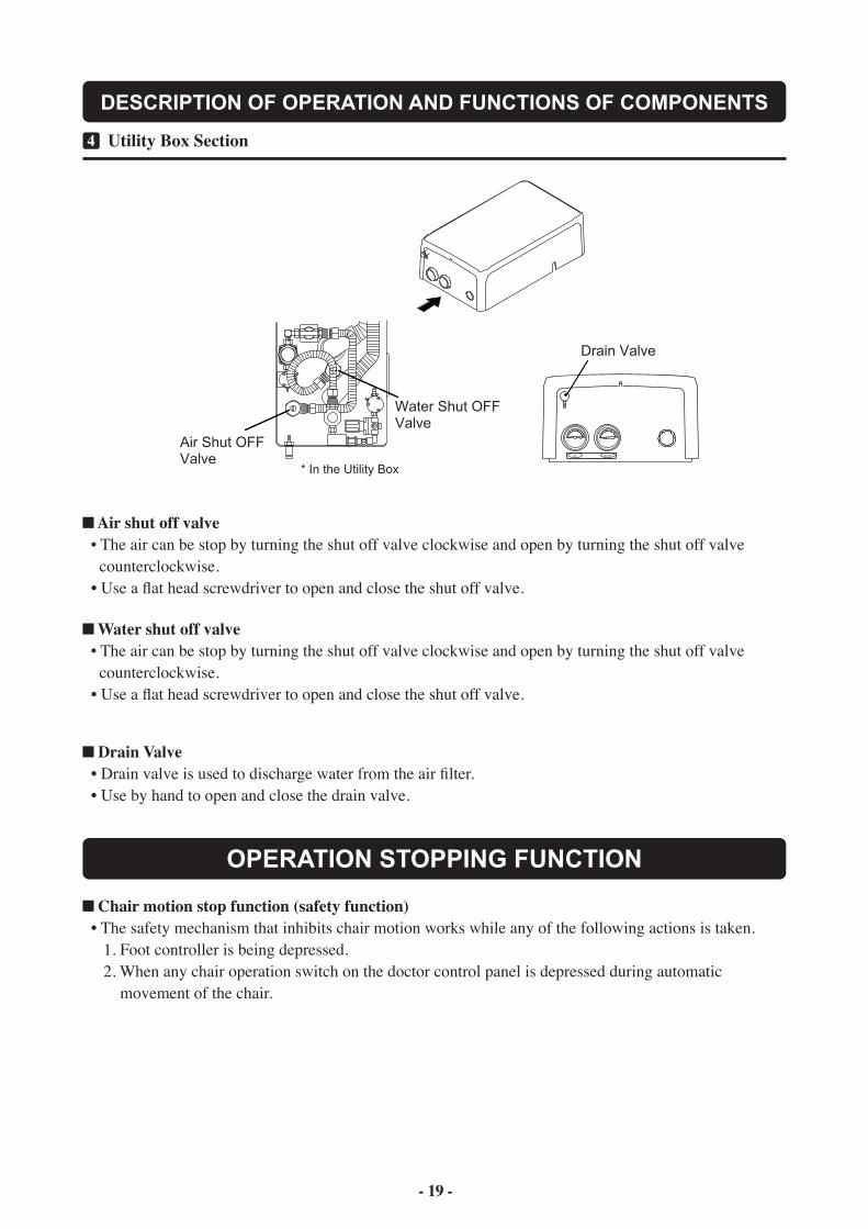
1 Utility Box Section4
Air shut off valve • The air can be stop by turning the shut off valve clockwise and open by turning the shut off valve counterclockwise. • Use a flat head screwdriver to open and close the shut off valve.
Water shut off valve • The air can be stop by turning the shut off valve clockwise and open by turning the shut off valve counterclockwise. • Use a flat head screwdriver to open and close the shut off valve.
Drain Valve • Drain valve is used to discharge water from the air filter. • Use by hand to open and close the drain valve.
Chair motion stop function (safety function) • The safety mechanism that inhibits chair motion works while any of the following actions is taken. 1. Foot controller is being depressed. 2. When any chair operation switch on the doctor control panel is depressed during automatic movement of the chair.
OPERATION STOPPING FUNCTION
- 19 - - 20 -
Handpiece spray water control knob
Syringe Air flow control knob
Syringe Water flow control knob
Increase Decrease
Syringe water control
Service outlet (water) (Optional)
Service outlet water flow control (Optional)
Syringe air control
Increase Decrease
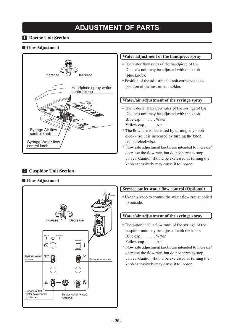
1 Doctor Unit Section1
Flow Adjustment
ADJUSTMENT OF PARTS
Water adjustment of the handpiece spray
Water/air adjustment of the syringe spray
• The water flow rates of the handpiece of the Doctor’s unit may be adjusted with the knob (blue knob).• Position of the adjustment knob corresponds to position of the instrument holder.
• The water and air flow rates of the syringe of the Doctor’s unit may be adjusted with the knob. Blue cap . . . . . Water Yellow cap . . . . Air* The flow rate is decreased by turning any knob clockwise. It is increased by turning the knob counterclockwise.* Flow rate adjustment knobs are intended to increase/ decrease the flow rate, but do not serve as stop valves. Caution should be exercised as turning the knob excessively may cause it to loosen.
Service outlet water flow control (Optional)
1 Cuspidor Unit Section2
Flow Adjustment
• Use this knob to control the water flow rate supplied to outside.
Water/air adjustment of the syringe spray
• The water and air flow rates of the syringe of the cuspidor unit may be adjusted with the knob. Blue cap . . . . . Water Yellow cap . . . . Air* Flow rate adjustment knobs are intended to increase/ decrease the flow rate, but do not serve as stop valves. Caution should be exercised as turning the knob excessively may cause it to loosen.
- 21 -
How to open the side panel
Side panel Side panel fixing screw
Flat head screwdriver
Air vacuum suction power control
Bowl flushflow control
Cupfiller flow control
Air vacuum
KnobKnob
Pull up
Push downPush down
Pull up
Main air pressure reducing valve
Main water pressure reducing valve
Increase
Decrease
Increase
Decrease
How to open the utility box cover
Phillips screwdriver
Cover fixing screw
Main water pressure gauge
Main air pressure gauge
Main air pressure reducing valve
Main water pressure reducing valve
* In the Utility Box
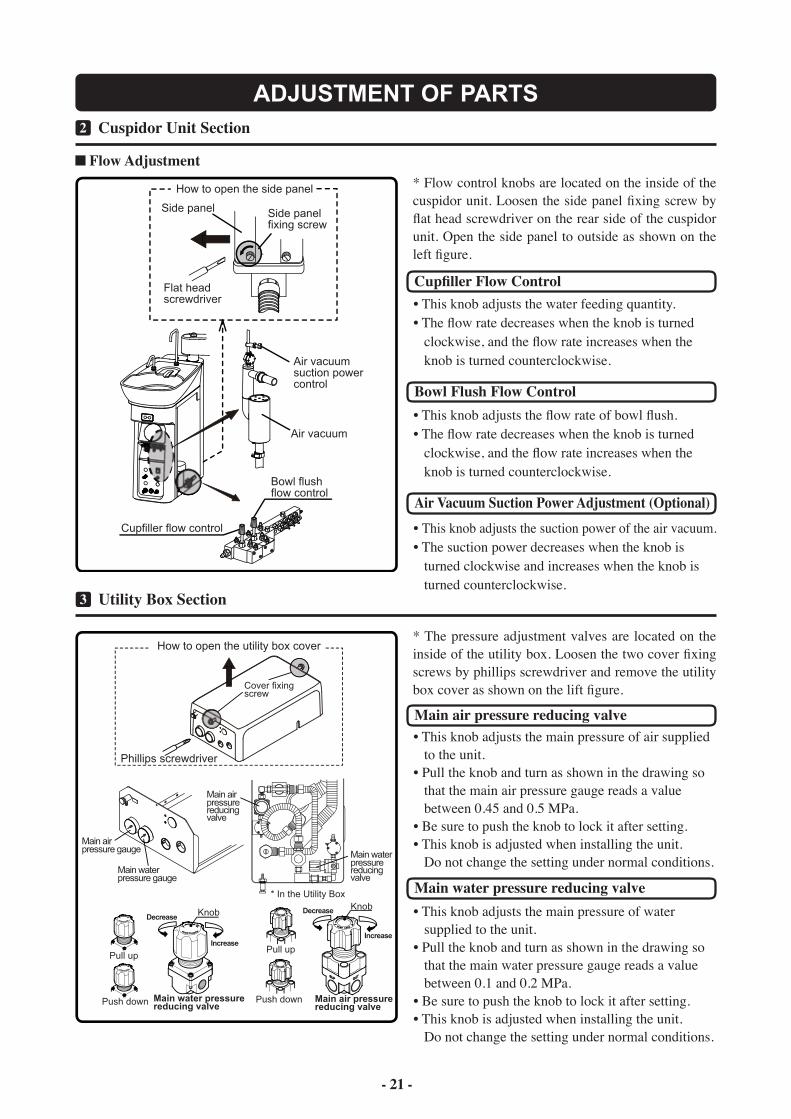
1 Cuspidor Unit Section2
Flow Adjustment
ADJUSTMENT OF PARTS
Cupfiller Flow Control• This knob adjusts the water feeding quantity. • The flow rate decreases when the knob is turned clockwise, and the flow rate increases when the knob is turned counterclockwise.
Bowl Flush Flow Control• This knob adjusts the flow rate of bowl flush.• The flow rate decreases when the knob is turned clockwise, and the flow rate increases when the knob is turned counterclockwise.
Air Vacuum Suction Power Adjustment (Optional)• This knob adjusts the suction power of the air vacuum. • The suction power decreases when the knob is turned clockwise and increases when the knob is turned counterclockwise.
* Flow control knobs are located on the inside of the cuspidor unit. Loosen the side panel fixing screw by flat head screwdriver on the rear side of the cuspidor unit. Open the side panel to outside as shown on the left figure.
1 Utility Box Section3
Main air pressure reducing valve• This knob adjusts the main pressure of air supplied to the unit.• Pull the knob and turn as shown in the drawing so that the main air pressure gauge reads a value between 0.45 and 0.5 MPa.• Be sure to push the knob to lock it after setting.• This knob is adjusted when installing the unit. Do not change the setting under normal conditions.
Main water pressure reducing valve• This knob adjusts the main pressure of water supplied to the unit.• Pull the knob and turn as shown in the drawing so that the main water pressure gauge reads a value between 0.1 and 0.2 MPa.• Be sure to push the knob to lock it after setting.• This knob is adjusted when installing the unit. Do not change the setting under normal conditions.
* The pressure adjustment valves are located on the inside of the utility box. Loosen the two cover fixing screws by phillips screwdriver and remove the utility box cover as shown on the lift figure.
- 21 - - 22 -
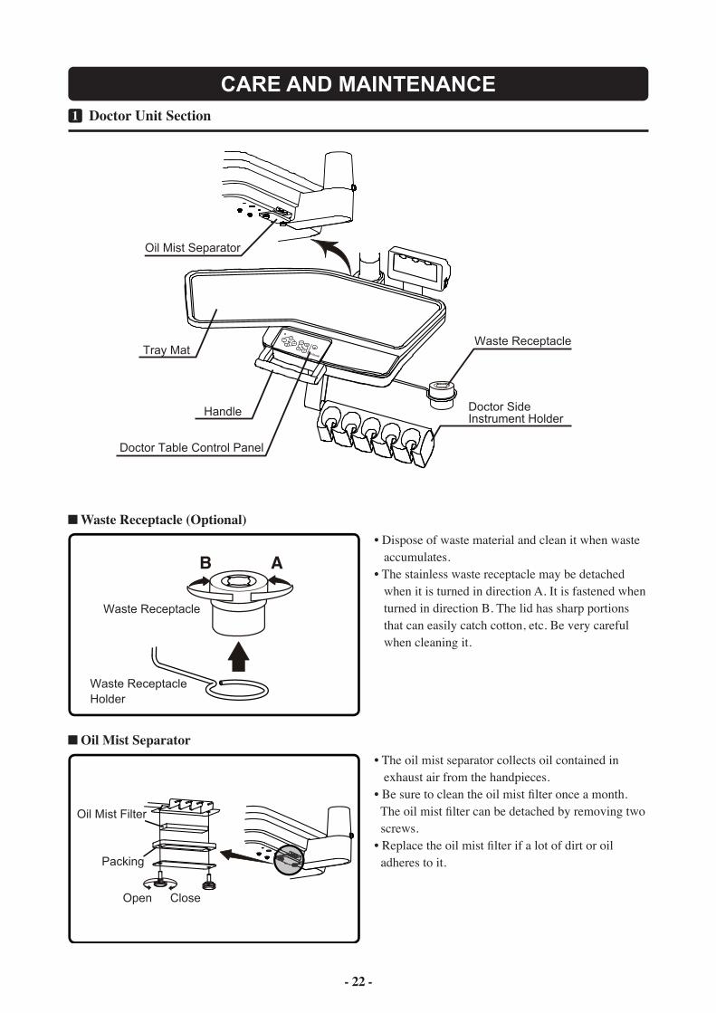
Oil Mist Separator
Tray Mat
Handle
Doctor Table Control Panel
Doctor SideInstrument Holder
Waste Receptacle
AB
Waste Receptacle
Waste ReceptacleHolder
Oil Mist Filter
Packing
Open Close
1 Doctor Unit Section1
CARE AND MAINTENANCE
Waste Receptacle (Optional)
Oil Mist Separator
• Dispose of waste material and clean it when waste accumulates.• The stainless waste receptacle may be detached when it is turned in direction A. It is fastened when turned in direction B. The lid has sharp portions that can easily catch cotton, etc. Be very careful when cleaning it.
• The oil mist separator collects oil contained in exhaust air from the handpieces.• Be sure to clean the oil mist filter once a month. The oil mist filter can be detached by removing two screws.• Replace the oil mist filter if a lot of dirt or oil adheres to it.

- 23 -
1 Doctor Unit Section1
CARE AND MAINTENANCE
Doctor Instrument Holder
Handle
Doctor Table Control Panel (Membrane Switch)
When the surface of the operation panel is cleaned with disinfectant, etc., wipe off disinfectant completely. If it penetrates into the back of the sheet, the membrane switches may malfunction.
CAUTION
• Wipe off the holder surface with soft cloth moistened with cleaner or disinfectant. Wipe off with dry soft cloth to dried up of the instrument holder after cleaning and disinfection.• Use the cleaner and disinfectant FD333/FD366 made by Durr. (Spray disinfectant mainly composed of disinfection ethanol and wipe it off, when general disinfectant is used.)
• Wipe off the handle with soft cloth moistened with cleaner or disinfectant. Wipe off with dry soft cloth to dried up of the handle after cleaning and disinfection.• Use the cleaner and disinfectant FD333/FD366 made by Durr. (Spray disinfectant mainly composed of disinfection ethanol and wipe it off, when general disinfectant is used.)
• Wipe off the doctor table control panel with soft cloth moistened with cleaner or disinfectant. Wipe off with dry soft cloth to dried up of the doctor table control panel after cleaning and disinfection.• Use the cleaner and disinfectant FD333/FD366 made by Durr. (Spray disinfectant mainly composed of disinfection ethanol and wipe it off, when general disinfectant is used.)
- 23 -
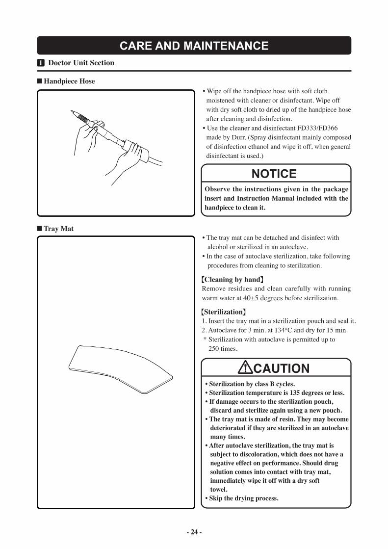
Handpiece Hose
Observe the instructions given in the package insert and Instruction Manual included with the handpiece to clean it.
NOTICE
1 Doctor Unit Section1
CARE AND MAINTENANCE
Tray Mat
CAUTION
- 24 -
• Wipe off the handpiece hose with soft cloth moistened with cleaner or disinfectant. Wipe off with dry soft cloth to dried up of the handpiece hose after cleaning and disinfection.• Use the cleaner and disinfectant FD333/FD366 made by Durr. (Spray disinfectant mainly composed of disinfection ethanol and wipe it off, when general disinfectant is used.)
• The tray mat can be detached and disinfect with alcohol or sterilized in an autoclave.• In the case of autoclave sterilization, take following procedures from cleaning to sterilization.
Cleaning by handRemove residues and clean carefully with running warm water at 40±5 degrees before sterilization.
Sterilization1. Insert the tray mat in a sterilization pouch and seal it.2. Autoclave for 3 min. at 134℃ and dry for 15 min. * Sterilization with autoclave is permitted up to 250 times.
• Sterilization by class B cycles.• Sterilization temperature is 135 degrees or less.• If damage occurs to the sterilization pouch, discard and sterilize again using a new pouch.• The tray mat is made of resin. They may become deteriorated if they are sterilized in an autoclave many times.• After autoclave sterilization, the tray mat is subject to discoloration, which does not have a negative effect on performance. Should drug solution comes into contact with tray mat, immediately wipe it off with a dry soft towel.• Skip the drying process.
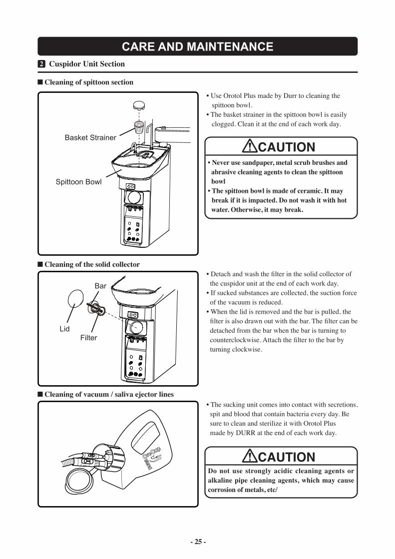
Basket Strainer
Spittoon Bowl
Bar
FilterLid
1 Cuspidor Unit Section2
CARE AND MAINTENANCE
Cleaning of spittoon section
• Use Orotol Plus made by Durr to cleaning the spittoon bowl.• The basket strainer in the spittoon bowl is easily clogged. Clean it at the end of each work day.
• Never use sandpaper, metal scrub brushes and abrasive cleaning agents to clean the spittoon bowl• The spittoon bowl is made of ceramic. It may break if it is impacted. Do not wash it with hot water. Otherwise, it may break.
CAUTION
Cleaning of the solid collector
Cleaning of vacuum / saliva ejector lines• The sucking unit comes into contact with secretions, spit and blood that contain bacteria every day. Be sure to clean and sterilize it with Orotol Plus made by DURR at the end of each work day.
Do not use strongly acidic cleaning agents or alkaline pipe cleaning agents, which may cause corrosion of metals, etc/
CAUTION
- 25 -
• Detach and wash the filter in the solid collector of the cuspidor unit at the end of each work day.• If sucked substances are collected, the suction force of the vacuum is reduced.• When the lid is removed and the bar is pulled, the filter is also drawn out with the bar. The filter can be detached from the bar when the bar is turning to counterclockwise. Attach the filter to the bar by turning clockwise.
- 25 -
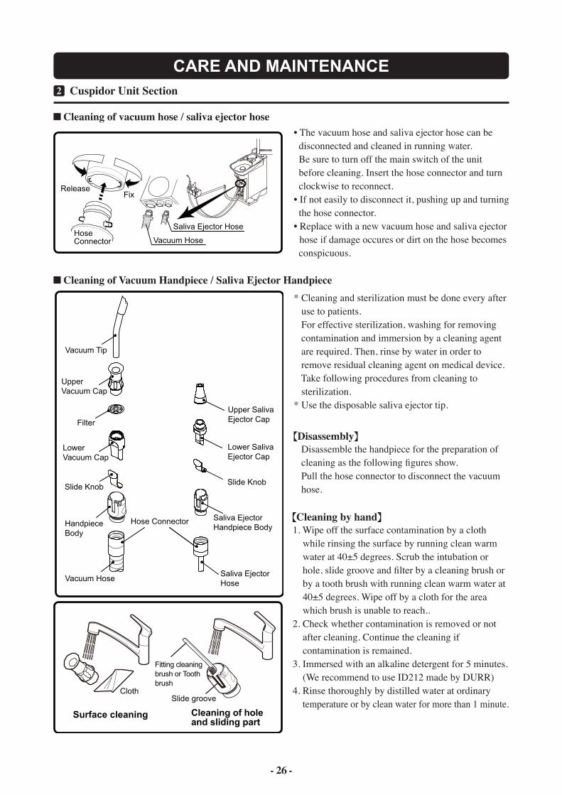
Upper SalivaEjector Cap
Saliva EjectorHose
Cloth
Surface cleaning
Fitting cleaning brush or Tooth brush
Slide groove
Cleaning of hole and sliding part
HoseConnector
FixRelease
Saliva Ejector Hose
Vacuum Hose
Vacuum Tip
Upper Vacuum Cap
Filter
Lower Vacuum Cap
Slide Knob
Handpiece Body
Vacuum Hose
Lower SalivaEjector Cap
Slide Knob
Saliva EjectorHandpiece Body
Hose Connector
- 26 -
1 Cuspidor Unit Section2
CARE AND MAINTENANCE
Cleaning of vacuum hose / saliva ejector hose
Cleaning of Vacuum Handpiece / Saliva Ejector Handpiece
• The vacuum hose and saliva ejector hose can be disconnected and cleaned in running water. Be sure to turn off the main switch of the unit before cleaning. Insert the hose connector and turn clockwise to reconnect.• If not easily to disconnect it, pushing up and turning the hose connector.• Replace with a new vacuum hose and saliva ejector hose if damage occures or dirt on the hose becomes conspicuous.
* Cleaning and sterilization must be done every after use to patients. For effective sterilization, washing for removing contamination and immersion by a cleaning agent are required. Then, rinse by water in order to remove residual cleaning agent on medical device. Take following procedures from cleaning to sterilization.* Use the disposable saliva ejector tip.
Disassembly Disassemble the handpiece for the preparation of cleaning as the following figures show. Pull the hose connector to disconnect the vacuum hose.
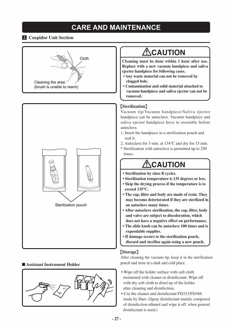
Cleaning by hand1. Wipe off the surface contamination by a cloth while rinsing the surface by running clean warm water at 40±5 degrees. Scrub the intubation or hole, slide groove and filter by a cleaning brush or by a tooth brush with running clean warm water at 40±5 degrees. Wipe off by a cloth for the area which brush is unable to reach..2. Check whether contamination is removed or not after cleaning. Continue the cleaning if contamination is remained.3. Immersed with an alkaline detergent for 5 minutes. (We recommend to use ID212 made by DURR)4. Rinse thoroughly by distilled water at ordinary temperature or by clean water for more than 1 minute.
CAUTION
Cloth
Sterilization pouch
Cleaning the area(brush is unable to reach)
- 27 -
1 Cuspidor Unit Section2
CARE AND MAINTENANCE
Cleaning must be done within 1 hour after use. Replace with a new vacuum handpiece and saliva ejector handpiece for following cases. • Any waste material can not be removed by clogged hole. • Contamination and solid material attached to vacuum handpiece and saliva ejector can not be removed.
CAUTION
Assistant Instrument Holder
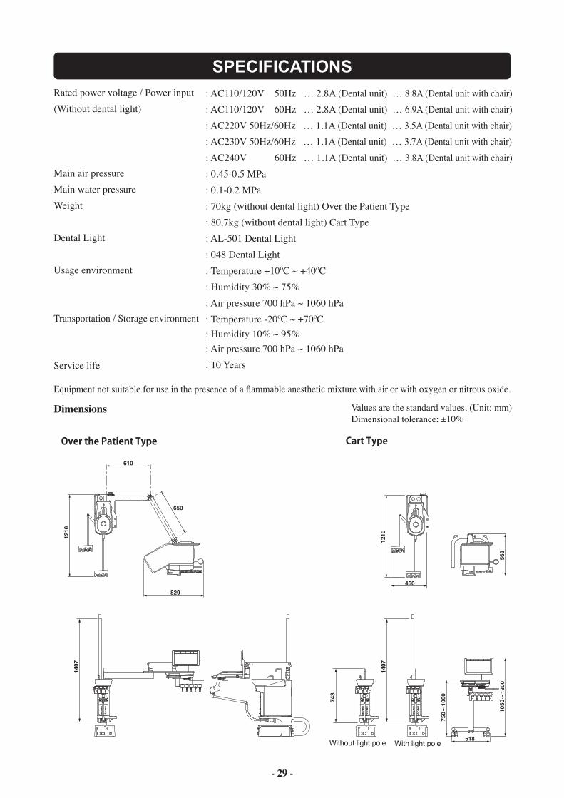
SterilizationVacuum tip/Vacuum handpiece/Saliva ejector handpiece can be autoclave. Vacuum handpiece and saliva ejector handpiece have to assemble before autoclave.1. Insert the handpiece in a sterilization pouch and seal it.2. Autoclave for 3 min. at 134℃ and dry for 15 min.* Sterilization with autoclave is permitted up to 250 times.
• Sterilization by class B cycles.• Sterilization temperature is 135 degrees or less.• Skip the drying process if the temperature is to exceed 135℃.• The cap, filter and body are made of resin. They may become deteriorated if they are sterilized in an autoclave many times.• After autoclave sterilization, the cap, filter, body and valve are subject to discoloration, which does not have a negative effect on performance.• The slide knob can be autoclave 100 times and is expendable supplies.• If damage occurs to the sterilization pouch, discard and sterilize again using a new pouch.
StorageAfter cleaning the vacuum tip, keep it in the sterilization pouch and store in a dark and cold place.
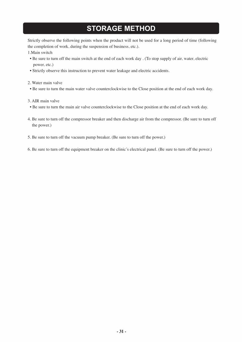
• Wipe off the holder surface with soft cloth moistened with cleaner or disinfectant. Wipe off with dry soft cloth to dried up of the holder after cleaning and disinfection.• Use the cleaner and disinfectant FD333/FD366 made by Durr. (Spray disinfectant mainly composed of disinfection ethanol and wipe it off, when general disinfectant is used.)

- 27 -
Drain Valve
Air Filter
Water Filter
1 Utility Box Section3
CARE AND MAINTENANCE
Cleaning air filter drain valve and discharging water from air compressor
Filter Replacement
1 Product Exterior4
Cleaning and Sterilization of product exterior• Clean the metallic parts with a dry soft cloth. Wipe off water immediately if water is put on the product. Water may cause rusting.• Clean the resin parts with a wet soft cloth.• Use FD333 or FD366 made by Durr or ethanol for cleaning and bacteria elimination from the product exterior.
• Wipe off water and residual disinfectant immediately. This could cause corrosion, damage or incorrect operation of the unit.• Immediately wipe off any water spills or leakage on the floor. This could cause damage to the product, decreased strength of the floor may lead to physical injury including fall, or property damage.
- 28 -
CAUTION
• Drain valve is used to discharge water from the air filter.• Connect the tubing to the drain valve and prepare the water pan such as paper cup. Turn the drain valve counterclockwise to discharge water collected in the air filter once a week at least.• If water enters the unit, the air turbine, air motor or syringe, etc., may become defective. Be sure to turn the drain valve clockwise to close the valve after discharging water from the air filter.• Open the drain valve of the air compressor to discharge collected water once a week according to the instruction manual of the compressor. It is recommend that the compressor with air dryer or auto drain function for use.
• The water filter in the utility box needs to be replaced at least once a year.• The air filter in the utility box needs to be replaced at least once every three years. Contact your local service representative for replacement.
1210
1210
1407
610
650
829
1407
743
563
1
050
1300
518
460
750
1000
With light poleWithout light pole
- 29 -
SPECIFICATIONSRated power voltage / Power input (Without dental light)
Main air pressure Main water pressure Weight Dental Light Usage environment
Transportation / Storage environment
Service life
Equipment not suitable for use in the presence of a flammable anesthetic mixture with air or with oxygen or nitrous oxide.
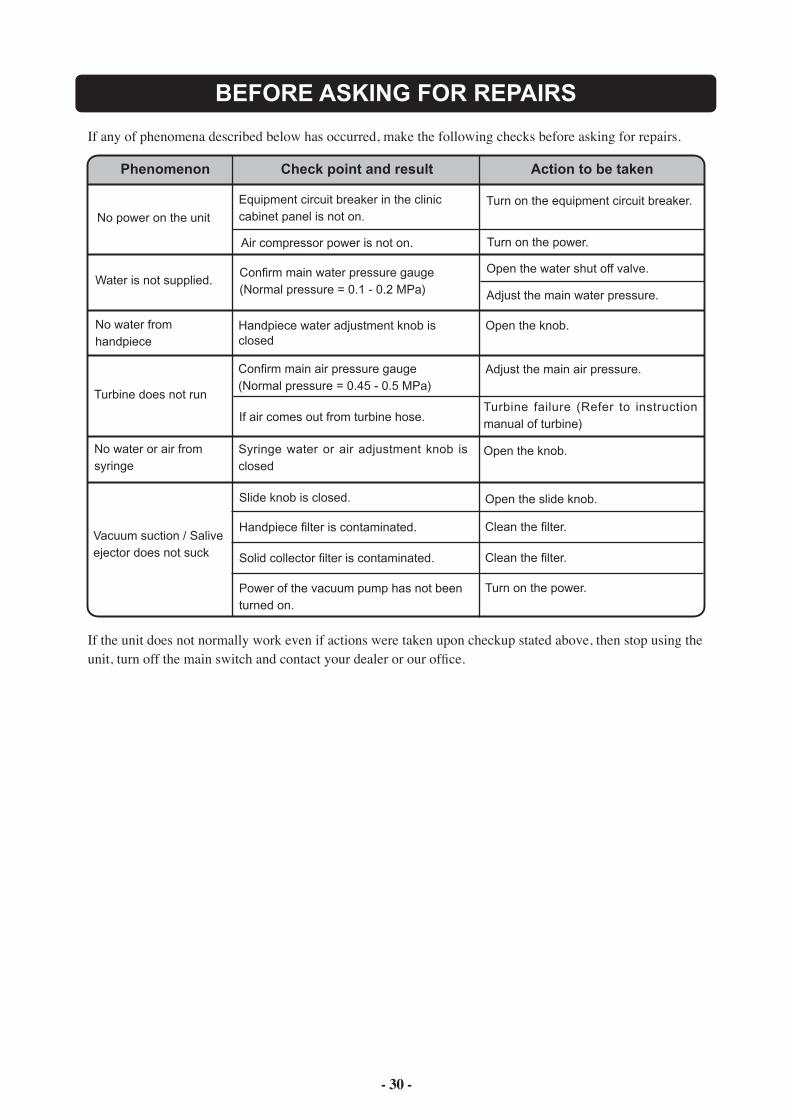
Dimensions Values are the standard values. (Unit: mm)Dimensional tolerance: ±10%
: AC110/120V 50Hz … 2.8A (Dental unit) … 8.8A (Dental unit with chair): AC110/120V 60Hz … 2.8A (Dental unit) … 6.9A (Dental unit with chair): AC220V 50Hz/60Hz … 1.1A (Dental unit) … 3.5A (Dental unit with chair): AC230V 50Hz/60Hz … 1.1A (Dental unit) … 3.7A (Dental unit with chair): AC240V 60Hz … 1.1A (Dental unit) … 3.8A (Dental unit with chair): 0.45-0.5 MPa: 0.1-0.2 MPa: 70kg (without dental light) Over the Patient Type: 80.7kg (without dental light) Cart Type: AL-501 Dental Light: 048 Dental Light: Temperature +10ºC ~ +40ºC: Humidity 30% ~ 75%: Air pressure 700 hPa ~ 1060 hPa: Temperature -20ºC ~ +70ºC: Humidity 10% ~ 95%: Air pressure 700 hPa ~ 1060 hPa : 10 Years
- 30 -
BEFORE ASKING FOR REPAIRS
If any of phenomena described below has occurred, make the following checks before asking for repairs.
Phenomenon Check point and result Action to be taken
No power on the unit
Air compressor power is not on. Turn on the power.
Water is not supplied.Confirm main water pressure gauge(Normal pressure = 0.1 - 0.2 MPa)
Open the water shut off valve.
Adjust the main water pressure.
Vacuum suction / Saliveejector does not suck
If the unit does not normally work even if actions were taken upon checkup stated above, then stop using theunit, turn off the main switch and contact your dealer or our office.
No water from handpiece
Handpiece water adjustment knob isclosed
Open the knob.
Turbine does not run
Confirm main air pressure gauge(Normal pressure = 0.45 - 0.5 MPa)
Adjust the main air pressure.
If air comes out from turbine hose.Turbine failure (Refer to instruction manual of turbine)
No water or air fromsyringe
Syringe water or air adjustment knob is closed
Open the knob.
Slide knob is closed.
Handpiece filter is contaminated.
Open the slide knob.
Clean the filter.
Solid collector filter is contaminated. Clean the filter.
Power of the vacuum pump has not beenturned on.
Turn on the power.
Equipment circuit breaker in the cliniccabinet panel is not on.
Turn on the equipment circuit breaker.
- 31 -
STORAGE METHOD
Strictly observe the following points when the product will not be used for a long period of time (following the completion of work, during the suspension of business, etc.).1.Main switch • Be sure to turn off the main switch at the end of each work day . (To stop supply of air, water, electric power, etc.) • Strictly observe this instruction to prevent water leakage and electric accidents.
2. Water main valve • Be sure to turn the main water valve counterclockwise to the Close position at the end of each work day.
3. AIR main valve • Be sure to turn the main air valve counterclockwise to the Close position at the end of each work day.
4. Be sure to turn off the compressor breaker and then discharge air from the compressor. (Be sure to turn off the power.)
5. Be sure to turn off the vacuum pump breaker. (Be sure to turn off the power.)
6. Be sure to turn off the equipment breaker on the clinic’s electrical panel. (Be sure to turn off the power.)
- 31 - - 32 -
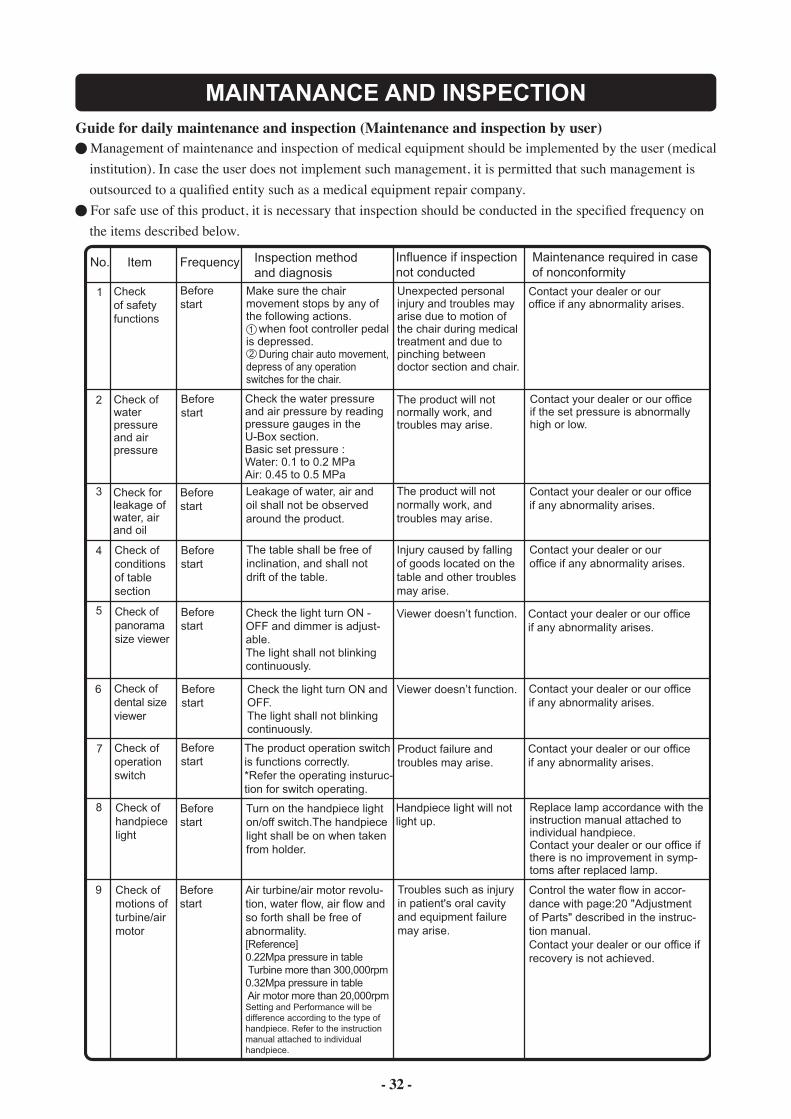
MAINTANANCE AND INSPECTIONGuide for daily maintenance and inspection (Maintenance and inspection by user)
Management of maintenance and inspection of medical equipment should be implemented by the user (medical institution). In case the user does not implement such management, it is permitted that such management is outsourced to a qualified entity such as a medical equipment repair company.
For safe use of this product, it is necessary that inspection should be conducted in the specified frequency on the items described below.
Before start
For each patient
For each patient
After closing
Sensor Cupfiller(option)
When a paper cup is placed on the cupfiller, the cup shall be detected and cupfilling shall be executed.* Malfunction may arise if the cup is of another material grade (such as stainless steel and plastics) or if the paper cup is of dark
Cupfilling may not be executed.
Execute re-inspection in accor-dance with "Method for operation" described in the instruction manual. Contact your dealer or our office if recovery is not achieved as a result of re-inspection.
Appropriate bar shall be positively mounted.Make sure to refer to the instruction manual attached to individual equipment.
The bar will not normally work and troubles may arise.
If abnormality such as flaw and deformation is found on the bar, replace the bar in accordance with the instruction manual attached to individual equipment.
Check of scaler tip
Appropriate tip shall be positively mounted and be correctly used.Make sure to refer to the instruction manual attached to the scaler.
The tip will not normally work and troubles may arise.
If the tip was worn or deformed, replace the tip in accordance with the instruction manual attached to the scaler.Contact your dealer or our office if any other trouble arises.
Check of tightness of syringe nut
The nut for fixing the nut of Type 77, 3-way syringe shall be positively tightened.
Troubles may arise if the nut comes off.
Turn and positively retighten the nut that fixes the nozzle.
Matters attached to micromotor
Excessive handpiece oil or the like shall not be attached to the motor section.
The motor section will not work normally and troubles may arise.
Execute care in accordance with the instruction manual attached to individual micromotor.
Air turbine/air motor revolu-tion, water flow, air flow and so forth shall be free of abnormality.[Reference]0.22Mpa pressure in table Turbine more than 300,000rpm0.32Mpa pressure in table Air motor more than 20,000rpmSetting and Performance will be difference according to the type of handpiece. Refer to the instruction manual attached to individual handpiece.
No. Item Frequency Inspection method and diagnosis
Influence if inspection not conducted
Maintenance required in case of nonconformity
Check of safety functions
Before start
Before start
Before start
Unexpected personal injury and troubles may arise due to motion of the chair during medical treatment and due to pinching between doctor section and chair.
Contact your dealer or our office if any abnormality arises.
Check for leakage of water, air and oil
Leakage of water, air and oil shall not be observed around the product.
The product will not normally work, and troubles may arise.
Contact your dealer or our office if any abnormality arises.
Check of motions of turbine/air motor
Troubles such as injury in patient's oral cavity and equipment failure may arise.
Control the water flow in accor-dance with page:20 "Adjustment of Parts" described in the instruc-tion manual. Contact your dealer or our office if recovery is not achieved.
Check of handpiece light
1
2
Check of water pressure and air pressure
Check the water pressure and air pressure by reading pressure gauges in the U-Box section.Basic set pressure : Water: 0.1 to 0.2 MPaAir: 0.45 to 0.5 MPa
The product will not normally work, and troubles may arise.
Contact your dealer or our office if the set pressure is abnormally high or low.
Before start
Check of conditions of table section
The table shall be free of inclination, and shall not drift of the table.
Injury caused by falling of goods located on the table and other troubles may arise.
Contact your dealer or our office if any abnormality arises.
Before start
1
2
3
4
Check of dental size viewer
Check of panorama size viewer
Before start
Before start
Contact your dealer or our office if any abnormality arises.
Contact your dealer or our office if any abnormality arises.
Viewer doesn’t function.
Viewer doesn’t function.
Check the light turn ON and OFF.The light shall not blinkingcontinuously.
Check the light turn ON - OFF and dimmer is adjust-able. The light shall not blinkingcontinuously.
5
6
7
8
9
Check of operation switch
The product operation switch is functions correctly.*Refer the operating insturuc-tion for switch operating.
Product failure and troubles may arise.
Contact your dealer or our office if any abnormality arises.
Before start
Before start
Replace lamp accordance with the instruction manual attached to individual handpiece.Contact your dealer or our office if there is no improvement in symp-toms after replaced lamp.
Turn on the handpiece light on/off switch.The handpiece light shall be on when taken from holder.
Handpiece light will not light up.
Make sure the chair movement stops by any of the following actions. when foot controller pedal is depressed. During chair auto movement, depress of any operation switches for the chair.
- 33 -
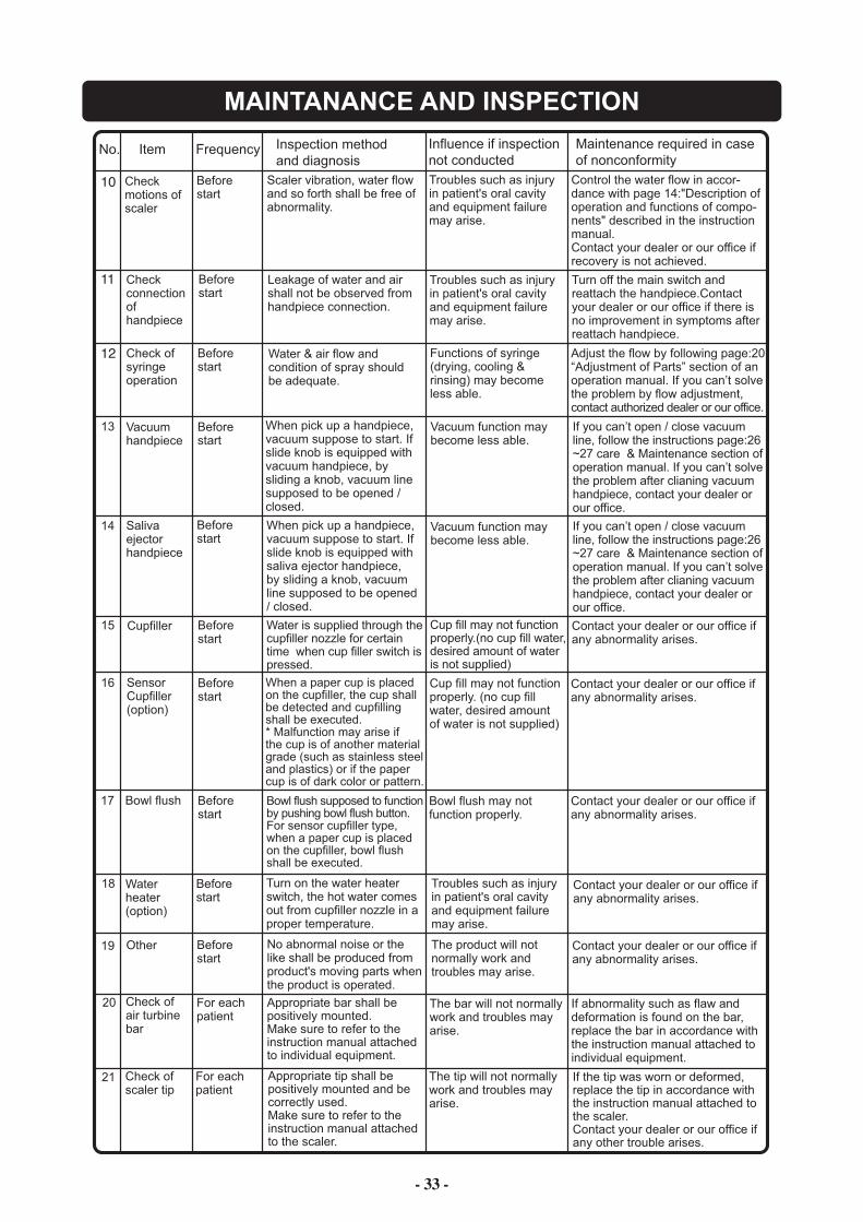
MAINTANANCE AND INSPECTION
No. Item Frequency Inspection method and diagnosis
Influence if inspection not conducted
Maintenance required in case of nonconformity
Other No abnormal noise or the like shall be produced from product's moving parts when the product is operated.
The product will not normally work and troubles may arise.
Contact your dealer or our office if any abnormality arises.
10
11
12
13
14
15
16
18
19
Check motions ofscaler
Before start
Scaler vibration, water flow and so forth shall be free of abnormality.
Troubles such as injury in patient's oral cavity and equipment failure may arise.
Control the water flow in accor-dance with page 14:"Description of operation and functions of compo-nents" described in the instruction manual. Contact your dealer or our office if recovery is not achieved.
Check connectionof handpiece
Before start
Leakage of water and air shall not be observed from handpiece connection.
Turn off the main switch and reattach the handpiece.Contact your dealer or our office if there is no improvement in symptoms after reattach handpiece.
Check of syringe operation
Before start
Troubles such as injury in patient's oral cavity and equipment failure may arise.
Vacuum handpiece
Before start
Saliva ejector handpiece
Before start
SensorCupfiller(option)
Before start
When a paper cup is placedon the cupfiller, the cup shallbe detected and cupfilling shall be executed.* Malfunction may arise ifthe cup is of another materialgrade (such as stainless steel and plastics) or if the paper cup is of dark color or pattern.
Bowl flush Before start
Before start
20 Check ofair turbinebar
For eachpatient
Appropriate bar shall bepositively mounted.Make sure to refer to theinstruction manual attachedto individual equipment.
The bar will not normallywork and troubles mayarise.
If abnormality such as flaw anddeformation is found on the bar,replace the bar in accordance withthe instruction manual attached toindividual equipment.
Check ofscaler tip
For eachpatient
Appropriate tip shall bepositively mounted and becorrectly used.Make sure to refer to theinstruction manual attachedto the scaler.
The tip will not normallywork and troubles mayarise.
If the tip was worn or deformed,replace the tip in accordance withthe instruction manual attached tothe scaler.Contact your dealer or our office ifany other trouble arises.
Contact your dealer or our office if any abnormality arises.
Water & air flow and condition of spray should be adequate.
Functions of syringe (drying, cooling & rinsing) may become less able.
Adjust the flow by following page:20 “Adjustment of Parts” section of an operation manual. If you can’t solve the problem by flow adjustment, contact authorized dealer or our office.
When pick up a handpiece, vacuum suppose to start. If slide knob is equipped with vacuum handpiece, by sliding a knob, vacuum line supposed to be opened / closed.
Vacuum function may become less able.
If you can’t open / close vacuum line, follow the instructions page:26~27 care & Maintenance section of operation manual. If you can’t solve the problem after clianing vacuum handpiece, contact your dealer or our office.
When pick up a handpiece, vacuum suppose to start. If slide knob is equipped with saliva ejector handpiece, by sliding a knob, vacuum line supposed to be opened / closed.
Vacuum function may become less able.
Cup fill may not function properly. (no cup fill water, desired amount of water is not supplied)
Contact your dealer or our office if any abnormality arises.
Bowl flush may not function properly.
Water heater(option)
Turn on the water heater switch, the hot water comes out from cupfiller nozzle in a proper temperature.
17
Before start
Cupfiller Before start
Water is supplied through thecupfiller nozzle for certain time when cup filler switch is pressed.
Cup fill may not functionproperly.(no cup fill water, desired amount of water is not supplied)
Contact your dealer or our office ifany abnormality arises.
21
Troubles such as injury in patient's oral cavity and equipment failure may arise.
Contact your dealer or our office if any abnormality arises.
If you can’t open / close vacuum line, follow the instructions page:26~27 care & Maintenance section of operation manual. If you can’t solve the problem after clianing vacuum handpiece, contact your dealer or our office.
Bowl flush supposed to function by pushing bowl flush button.For sensor cupfiller type, when a paper cup is placedon the cupfiller, bowl flush shall be executed.
- 34 -
MAINTANANCE AND INSPECTION
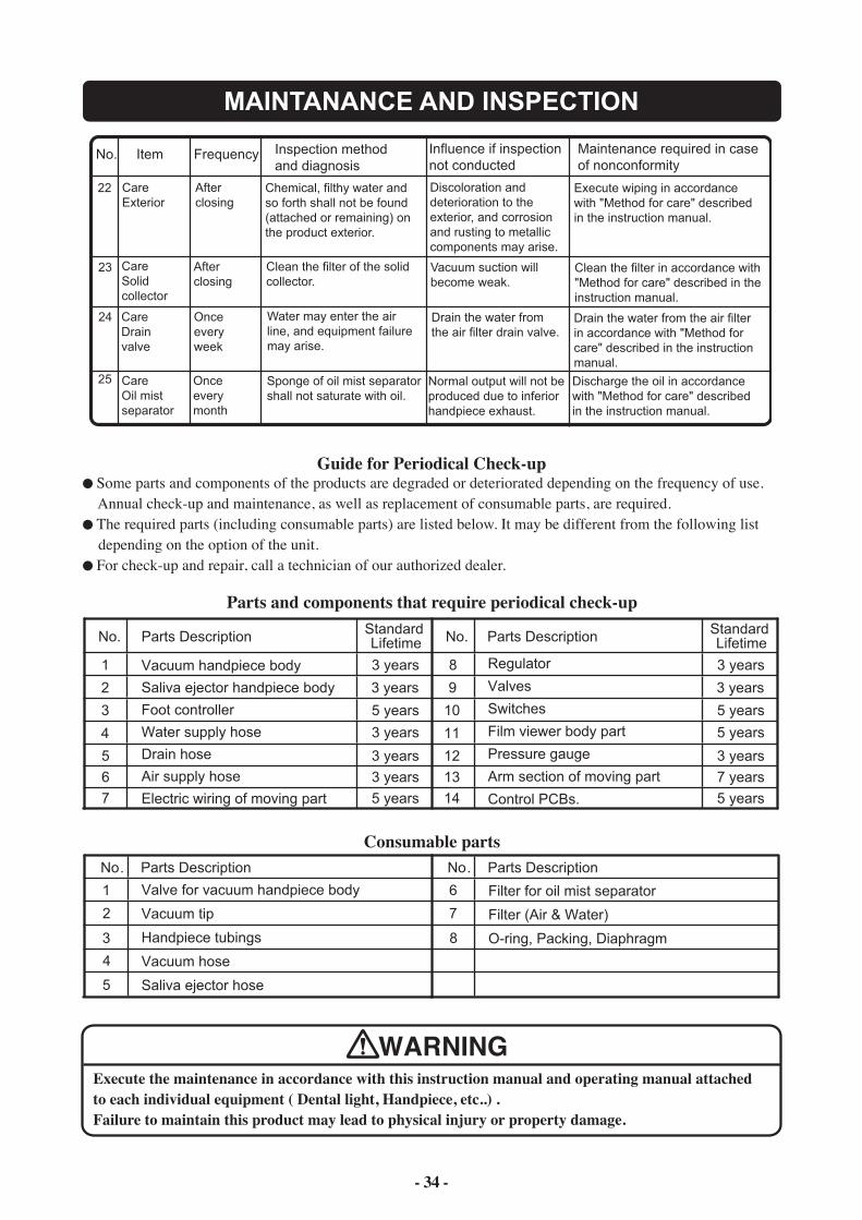
Guide for Periodical Check-up Some parts and components of the products are degraded or deteriorated depending on the frequency of use.
Annual check-up and maintenance, as well as replacement of consumable parts, are required. The required parts (including consumable parts) are listed below. It may be different from the following list
depending on the option of the unit. For check-up and repair, call a technician of our authorized dealer.
Parts Description
Vacuum handpiece body
Saliva ejector handpiece body
Foot controller
Water supply hose
Drain hose
Air supply hose
Electric wiring of moving part
Standard LifetimeNo.
3 years 1
2 3 years
3 5 years
3 years
3
4
4
5 3 years
No. Parts Description
1
2
Parts Description Standard LifetimeNo.
3 years 8
9 3 years
10 5 years
5 years11
12 3 years
Regulator
Valves
Switches
Film viewer body part
Pressure gauge
Arm section of moving part
Control PCBs.
6 3 years 13 7 years
7 5 years 14 5 years
Valve for vacuum handpiece body
Vacuum tip
Handpiece tubings
Vacuum hose
Saliva ejector hose
8
No. Parts Description
6
7
Filter for oil mist separator
Filter (Air & Water)
O-ring, Packing, Diaphragm
5
WARNINGExecute the maintenance in accordance with this instruction manual and operating manual attachedto each individual equipment ( Dental light, Handpiece, etc..) .Failure to maintain this product may lead to physical injury or property damage.
Parts and components that require periodical check-up
Consumable parts
No. Item Frequency Inspection method and diagnosis
Influence if inspection not conducted
Maintenance required in case of nonconformity
22
23
24
25
CareExterior
Chemical, filthy water and so forth shall not be found (attached or remaining) on the product exterior.
Discoloration and deterioration to the exterior, and corrosion and rusting to metallic components may arise.
Execute wiping in accordance with "Method for care" described in the instruction manual.
After closing
CareSolid collector
Clean the filter of the solid collector.
Vacuum suction will become weak.
Clean the filter in accordance with "Method for care" described in the instruction manual.
After closing
CareDrain valve
Drain the water from the air filter drain valve.
Water may enter the air line, and equipment failure may arise.
Drain the water from the air filter in accordance with "Method for care" described in the instruction manual.
Once every week
Care Oil mist separator
Normal output will not be produced due to inferior handpiece exhaust.
Discharge the oil in accordance with "Method for care" described in the instruction manual.
Once every month
Sponge of oil mist separator shall not saturate with oil.
NOTE
2-1-1, Higashishinsaibashi,Chuo-ku,Osaka, 542-0083,JapanTEL : +81 6 6213 5945 FAX : +81 6 6212 3680www.takara-net.com
TAKARA BELMONT CORPORATION


![Model No. TH-L65WT600A TH-L65WT600Z - panasonic.com€¦ · Operating Instructions LED TV English For more detailed instructions, refer to [eHELP] (Built-in Operating Instructions)](https://img.pdfslide.tips/doc/110x75/5b57aada7f8b9aec628b6a01/model-no-th-l65wt600a-th-l65wt600z-operating-instructions-led-tv-english.jpg)