Embed Size (px)
Citation preview

담 당 관 리 자
Model Description
MODEL BRAND
Printing Specification
1. Trim Size (Format) : 185mm x 260 mm2. Printing Colors• Cover : 1 COLOR (BLACK)• Inside : 1 COLOR (BLACK)3. Stock (Paper)• Cover : Coated paper , S/White 150 g/㎡• Inside : Uncoated paper , 백상지 60 g/㎡4. Printing Method : Off set5. Bindery : Saddle stitch6. Language : English (1)7. Number of pages : 40
Part No.
1.
2.
User’s Guide SpecificationUser’s Guide Specification
Changes 4.
REV.NO. MM/DD/YY SIGNATURE CHANGE NO. CHANGE CONTENTS
1
2
3
4
5
7
6
SUFFIX
LG/30/50/60/70-UAPG60/60F-UA LG
MFL34797048(0809-REV08)
KANG KWANG SUK
07.11.22
8
9
Special Instructions3.
Product NameUSA
Park SY07.11.22
LG30/50/60/70PG25/60
“This part contain Eco-hazardous substances (Pb, Cd, Hg, Cr6+, PBB, PBDE, etc.) within LG standard level, Details should be followed Eco-SCM management standard[LG(56)-A-2524].Especially, Part should be followed and controlled the following specification.(1)Eco-hazardous substances test report should be submitted
when Part certification test and First Mass Production.(2) Especially, Don’t use or contain lead(Pb) and cadmium(Cd) in ink.
NOTES
(1) Origin Notification* LGEMX : Printed in Mexico* LGERS : Printed in Mexico* LGEAZ : Printed in Brazil* LGESP : Printed in Brazil * LGESY : Printed in China
* LGENT : Printed in China * LGENP : Printed in China* LGEIL : Printed in India * LGEDI : Printed in Indonesia* LGEIN : Printed in Indonesia
* LGETH : Printed in Thailand* LGEVN : Printed in Vietnam
* LGEMA : Printed in Poland* LGEWA : Printed in U.K.* LGEEG : Printed in Egypt* LGERA : Printed in Russia * LGEAK : Printed in Kazakhstan
Jan./21/07 Park sun young S8-06718 Applied PQ test results for LG30/50-UA.
Feb./13/07 Park sun young S8-09351 Deleted RF cable.
Mar./12/08 Park sun young S8-11223 Applied LG60/70, 60/60F PQ test results.
Mar./18/08 Park sun young S8-14016 Changed GNU License contents for LG30-UD,LG50-UG.
Apr./18/08 Park sun young S8-16712 Added the screw for 42LG30/50.
May./16/08 Park sun young S8-20239 Applied PQ test results of 47LG90.
July/23/08 Park sun young S8-26219 Added 47LG61 model, Ferrite core, ISFccc logo.
Sep./08/08 Park sun young S8-29785 Added the screw (1EA) to meet vertical force stability for 37LG30/50.
Pagination sheetPagination sheet P/NO.MFL34797048Total pages : 40 pages
2 ….
Front cover
…. ….
LG(EN)
… 39P/NO.
Rear cover
ChildSafety

Please read this manual carefully before operatingyour set. Retain it for future reference.Record model number and serial number of the set. See the label attached on the back cover and quote this information to your dealer when you require service.
LCD TV PLASMA TVOWNER’S MANUALLCD TV MODELS32LG30 37LG5037LG30 42LG5042LG30 47LG5042LGX 52LG5047LGX32LG60 32LG7037LG60 42LG7042LG60 47LG7047LG60 52LG7052LG60
47LG90
PLASMA TV MODELS42PG2550PG25
50PG6060PG60
50PG7060PG70
P/NO : MFL34797048 (0809-REV08)Printed in Korea
www.lgusa.com
As an ENERGY STAR PartnerLG Electronics USA, Inc.has determined that thisproduct meets the ENERGYSTAR guidelines for energyefficiency.
ENERGY STAR is a set of power-savingguidelines issued by the U.S.Environmental Protection Agency (EPA).
An extended owner’s manual that contains informationon the advanced features of these LG TV sets is locatedon the CD-ROM provided in an electronic version.
To read these files, you will need to use personal computer(PC) equipped with a CD-ROM drive.
MFL34797048-en-8-ING 9/8/2008 3:53 PM Page 1

2
WARNING / CAUTION
WARNING / CAUTION
To prevent fire or shock hazards, do not expose
this product to rain or moisture.
FCC NOTICE
Class B digital device
This equipment has been tested and found to com-ply with the limits for a Class B digital device, pur-suant to Part 15 of the FCC Rules. These limits aredesigned to provide reasonable protection againstharmful interference in a residential installation. Thisequipment generates, uses and can radiate radio fre-quency energy and, if not installed and used inaccordance with the instructions, may cause harmfulinterference to radio communications. However,there is no guarantee that interference will notoccur in a particular installation. If this equipmentdoes cause harmful interference to radio or televi-sion reception, which can be determined by turningthe equipment off and on, the user is encouraged totry to correct the interference by one or more ofthe following measures:
- Reorient or relocate the receiving antenna.
- Increase the separation between the equipmentand receiver.
- Connect the equipment to an outlet on a circuitdifferent from that to which the receiver is con-nected.
- Consult the dealer or an experienced radio/TVtechnician for help.
Any changes or modifications not expresslyapproved by the party responsible for compliancecould void the user’s authority to operate theequipment.
CAUTION
Do not attempt to modify this product in any waywithout written authorization from LG Electronics.Unauthorized modification could void the user’sauthority to operate this product
The lightning flash with arrowheadsymbol, within an equilateral triangle,is intended to alert the user to the
presence of uninsulated “dangerous voltage”within the product’s enclosure that may be ofsufficient magnitude to constitute a risk of electricshock to persons.
The exclamation point within an equilateraltriangle is intended to alert the user to
the presence of important operating and main-tenance (servicing) instructions in the literatureaccompanying the appliance.
TO REDUCE THE RISK OF ELECTRIC SHOCK
DO NOT REMOVE COVER (OR BACK). NO
USER SERVICEABLE PARTS INSIDE. REFER TO
QUALIFIED SERVICE PERSONNEL.
WARNING/CAUTION
TO REDUCE THE RISK OF FIRE AND ELECTRIC
SHOCK, DO NOT EXPOSE THIS PRODUCT TO
RAIN OR MOISTURE.
NOTE TO CABLE/TV INSTALLER
This reminder is provided to call the CATV systeminstaller’s attention to Article 820-40 of the NationalElectric Code (U.S.A.). The code provides guidelines forproper grounding and, in particular, specifies that thecable ground shall be connected to the grounding sys-tem of the building, as close to the point of the cableentry as practical.
MFL34797048-en-8-ING 9/8/2008 3:53 PM Page 2
3
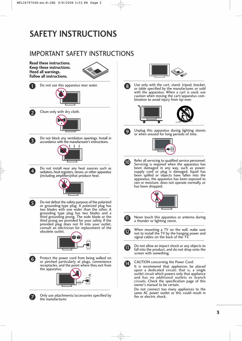
IMPORTANT SAFETY INSTRUCTIONS
SAFETY INSTRUCTIONS
Read these instructions.Keep these instructions.Heed all warnings.Follow all instructions.
Do not use this apparatus near water.
Clean only with dry cloth.
Do not block any ventilation openings. Install inaccordance with the manufacturer’s instructions.
Do not install near any heat sources such asradiators, heat registers, stoves, or other apparatus(including amplifiers)that produce heat.
Do not defeat the safety purpose of the polarizedor grounding-type plug. A polarized plug hastwo blades with one wider than the other. Agrounding type plug has two blades and athird grounding prong, The wide blade or thethird prong are provided for your safety. If theprovided plug does not fit into your outlet,consult an electrician for replacement of theobsolete outlet.
Protect the power cord from being walked onor pinched particularly at plugs, conveniencereceptacles, and the point where they exit fromthe apparatus.
Only use attachments/accessories specified bythe manufacturer.
Use only with the cart, stand, tripod, bracket,or table specified by the manufacturer, or soldwith the apparatus. When a cart is used, usecaution when moving the cart/apparatus com-bination to avoid injury from tip-over.
Unplug this apparatus during lighting stormsor when unused for long periods of time.
Refer all servicing to qualified service personnel.Servicing is required when the apparatus hasbeen damaged in any way, such as power-supply cord or plug is damaged, liquid hasbeen spilled or objects have fallen into theapparatus, the apparatus has been exposed torain or moisture, does not operate normally, orhas been dropped.
Never touch this apparatus or antenna duringa thunder or lighting storm.
When mounting a TV on the wall, make surenot to install the TV by the hanging power andsignal cables on the back of the TV.
Do not allow an impact shock or any objects tofall into the product, and do not drop onto thescreen with something.
CAUTION concerning the Power Cord:It is recommend that appliances be placedupon a dedicated circuit; that is, a singleoutlet circuit which powers only that applianceand has no additional outlets or branchcircuits. Check the specification page of thisowner's manual to be certain.Do not connect too many appliances to thesame AC power outlet as this could result infire or electric shock.
1 8
9
10
11
12
13
14
2
3
4
5
6
7
MFL34797048-en-8-ING 9/8/2008 3:53 PM Page 3

4
SAFETY INSTRUCTIONS
Do not overload wall outlets. Overloaded walloutlets, loose or damaged wall outlets, extensioncords, frayed power cords, or damaged orcracked wire insulation are dangerous. Any ofthese conditions could result in electric shockor fire. Periodically examine the cord of yourappliance, and if its appearance indicates damageor deterioration, unplug it, discontinue use ofthe appliance, and have the cord replaced withan exact replacement part by an authorizedservicer. Protect the power cord from physicalor mechanical abuse, such as being twisted,kinked, pinched, closed in a door, or walkedupon. Pay particular attention to plugs, walloutlets, and the point where the cord exits theappliance. Do not make the TV with the power cordplugged in. Do not use a damaged or loosepower cord. Be sure do grasp the plug whenunplugging the power cord. Do not pull on thepower cord to unplug the TV.
WARNING - To reduce the risk of fire or elec-trical shock, do not expose this product to rain,moisture or other liquids. Do not touch the TVwith wet hands. Do not install this product nearflammable objects such as gasoline or candlesor expose the TV to direct air conditioning.
Do not expose to dripping or splashing and donot place objects filled with liquids, such asvases, cups, etc. on or over the apparatus (e.g.on shelves above the unit).
GGRROOUUNNDDIINNGGEnsure that you connect the earth ground wireto prevent possible electric shock (i.e. a TVwith a three-prong grounded AC plug must beconnected to a three-prong grounded AC out-let). If grounding methods are not possible,have a qualified electrician install a separatecircuit breaker. Do not try to ground the unit by connecting itto telephone wires, lightening rods, or gas pipes.
DDIISSCCOONNNNEECCTTIINNGG DDEEVVIICCEE FFRROOMM MMAAIINNSSMains plug is the disconnecting device. Theplug must remain readily operable.
Keep the product away from direct sunlight.
AANNTTEENNNNAASSOOuuttddoooorr aanntteennnnaa ggrroouunnddiinnggIf an outdoor antenna is installed, follow theprecautions below. An outdoor antenna systemshould not be located in the vicinity of over-head power lines or other electric light orpower circuits, or where it can come in contactwith such power lines or circuits as death orserious injury can occur.Be sure the antenna system is grounded so asto provide some protection against voltagesurges and built-up static charges. Section 810 of the National Electrical Code(NEC) in the U.S.A. provides information withrespect to proper grounding of the mast andsupporting structure, grounding of the lead-inwire to an antenna discharge unit, size ofgrounding conductors, location of antenna dis-charge unit, connection to grounding electrodesand requirements for the grounding electrode. AAnntteennnnaa ggrroouunnddiinngg aaccccoorrddiinngg ttoo tthheeNNaattiioonnaall EElleeccttrriiccaall CCooddee,, AANNSSII//NNFFPPAA 7700
CClleeaanniinnggWhen cleaning, unplug the power cord andscrub gently with a soft cloth to preventscratching. Do not spray water or other liquidsdirectly on the TV as electric shock may occur.Do not clean with chemicals such as alcohol,thinners or benzene.
MMoovviinnggMake sure the product is turned off,unplugged and all cables have been removed. Itmay take 2 or more people to carry larger TVs.Do not press against or put stress on the frontpanel of the TV.
VVeennttii llaattiioonnInstall your TV where there is proper ventila-tion. Do not install in a confined space such asa bookcase. Do not cover the product withcloth or other materials (e.g.) plastic whileplugged in. Do not install in excessively dustyplaces.
If you smell smoke or other odors coming fromthe TV or hear strange sounds, unplug thepower cord contact an authorized service center.
Do not press strongly upon the panel withhand or sharp object such as nail, pencil orpen, or make a scratch on it.
Power Supply
Short-circuitBreaker
Antenna Lead in Wire
Antenna Discharge Unit(NEC Section 810-20)
Grounding Conductor(NEC Section 810-21)
Ground Clamps
Power Service GroundingElectrode System (NECArt 250, Part H)
Ground Clamp
Electric ServiceEquipment
NEC: National Electrical Code
15
20
21
22
23
24
25
16
17
18
19
MFL34797048-en-8-ING 9/8/2008 3:53 PM Page 4

5
CONTENTS
HOW TO USE THE OWNER'S MANUAL ON THE CD-ROMTo view the Owner's Manual on the CD-ROM, Adobe Acrobat Reader must be installed on your PC.The “ACRORD" folder on the CD-ROM contains the installation programs for them.If you want to install those programs, Open the “My Computer” Open the “LG” Open the“ACRORD” double-click your language.
TO VIEW THE OWNER'S MANUAL ON THE CD-ROMThe Owner's Manual files are included in the supplied CD-ROM.Load the supplied CD-ROM into the CD-ROM drive of your PC.After a while, the web page of the CD-ROM will open automatically. (for Window only)
GG If the web page does not appear automatically, open the Owner's Manual file directly.Open the “My computer” Open the “LG” Open the “index.htm” file.NOTE!
FOR LCD TV� If the TV feels cold to the touch, there may be a small “flicker” when it is turned on. This is normal, there
is nothing wrong with TV.� Some minute dot defects may be visible on the screen, appearing as tiny red, green, or blue spots. However, they
have no adverse effect on the monitor's performance.� Avoid touching the LCD screen or holding your finger(s) against it for long periods of time. Doing so may
produce some temporary distortion effects on the screen.On Disposal (Only Hg lamp used LCD TV)The fluorescent lamp used in this product contains a small amount of mercury. Do not dispose of thisproduct with general household waste. Disposal of this product must be carried out in accordance to theregulations of your local authority.
When you select your product,display the PDF file.
You can find the desired contentseasily using the bookmark.
WARNING / CAUTION . . . . . . . . . . . . . . . . . . . . . . . . . . . . 2
SAFETY INSTRUCTIONS . . . . . . . . . . . . . . . . . . . . . . . . . . 3
PREPARATION
Accessories . . . . . . . . . . . . . . . . . . . . . . . . . . . . . . . . . . . . . . . . . . . . . . . . . . . . . . 6Front Panel Information . . . . . . . . . . . . . . . . . . . . . . . . . . . . . . . . . . . . . .7Back Panel Information . . . . . . . . . . . . . . . . . . . . . . . . . . . . . . . . . . . . . . 8Remote Control Functions . . . . . . . . . . . . . . . . . . . . . . . . . . . . . . . 10Stand Instruction . . . . . . . . . . . . . . . . . . . . . . . . . . . . . . . . . . . . . . . . . . . . . 11VESA Wall Mounting . . . . . . . . . . . . . . . . . . . . . . . . . . . . . . . . . . . . . . . . 15Cable Management . . . . . . . . . . . . . . . . . . . . . . . . . . . . . . . . . . . . . . . . . 16Desktop Pedestal Installation . . . . . . . . . . . . . . . . . . . . . . . . . . . . 18Swivel Stand . . . . . . . . . . . . . . . . . . . . . . . . . . . . . . . . . . . . . . . . . . . . . . . . . . . . 18Attaching the TV to a Desk . . . . . . . . . . . . . . . . . . . . . . . . . . . . . . 18Securing the TV to the wall to prevent falling whenthe tv is used on a stand . . . . . . . . . . . . . . . . . . . . . . . . . . . . . . . . 19Antenna or Cable Connection . . . . . . . . . . . . . . . . . . . . . . . . . . 20
EXTERNAL EQUIPMENT SETUP
HD Receiver Setup . . . . . . . . . . . . . . . . . . . . . . . . . . . . . . . . . . . . . . . . . 21DVD Setup . . . . . . . . . . . . . . . . . . . . . . . . . . . . . . . . . . . . . . . . . . . . . . . . . . . . . 22
VCR Setup . . . . . . . . . . . . . . . . . . . . . . . . . . . . . . . . . . . . . . . . . . . . . . . . . . . . . 23PC Setup . . . . . . . . . . . . . . . . . . . . . . . . . . . . . . . . . . . . . . . . . . . . . . . . . . . . . . . . 24
WATCHING TV
Turning On TV . . . . . . . . . . . . . . . . . . . . . . . . . . . . . . . . . . . . . . . . . . . . . . . . 25Channel Setup . . . . . . . . . . . . . . . . . . . . . . . . . . . . . . . . . . . . . . . . . . . . . . . . 25Initial Setting . . . . . . . . . . . . . . . . . . . . . . . . . . . . . . . . . . . . . . . . . . . . . . . . . . 26Quick Menu . . . . . . . . . . . . . . . . . . . . . . . . . . . . . . . . . . . . . . . . . . . . . . . . . . . . 27On-Screen Menus Selection . . . . . . . . . . . . . . . . . . . . . . . . . . . . . 27
USB
Entry Modes . . . . . . . . . . . . . . . . . . . . . . . . . . . . . . . . . . . . . . . . . . . . . . . . . . . 30Photo List . . . . . . . . . . . . . . . . . . . . . . . . . . . . . . . . . . . . . . . . . . . . . . . . . . . . . . . 31Music List . . . . . . . . . . . . . . . . . . . . . . . . . . . . . . . . . . . . . . . . . . . . . . . . . . . . . . . 33
APPENDIX
Troubleshooting . . . . . . . . . . . . . . . . . . . . . . . . . . . . . . . . . . . . . . . . . . . . . . 35Maintenance . . . . . . . . . . . . . . . . . . . . . . . . . . . . . . . . . . . . . . . . . . . . . . . . . . . 36Product Specifications . . . . . . . . . . . . . . . . . . . . . . . . . . . . . . . . . . . . . 37Open Source Software Notice . . . . . . . . . . . . . . . . . . . . . . . . . . 39
MFL34797048-en-8-ING 9/8/2008 3:53 PM Page 5

PR
EPA
RA
TIO
N
6
PREPARATION
ACCESSORIESEnsure that the following accessories are included with your TV. If an accessory is missing, please contact the
dealer where you purchased the product.
The accessories included may differ from the images below.
For further information, see the the Owner's Manual files supplied CD-ROM.
OOppttiioonn EExxttrraass
FFoorr LLCCDD TTVV mmooddeellss
FFoorr PPllaassmmaa TTVV mmooddeellss
* Wipe spots on the exterior only with
the polishing cloth.
* Do not wipe roughly when removing
stain. Excessive pressure may cause
scratch or discoloration.
Polishing Cloth(This feature is not available
for all models.)
Copyright© 2007 LGE,All Rights Reserved.
D-sub 15 pin Cable
1.5V 1.5V
Owner’s Manual Power CordRemote Control,Batteries
INPUT
FAV
MUTE
TVSTB
POWERQ. MENU
MENU
AV MODE
RETURN
ENTER
VOL
CH1
2
3
4
5
6
7
8
0 9FLASHBK
PA
GE
DVDVCR
CD Manual(Refer to p.5)
When using the VGA (D-sub 15 pin
cable) PC connection, the user
must use shielded signal interface
cables with ferrite cores to maintain
standards compliance.
32/37/42LG30, 37/42/47/52LG50, 32/42/47/52LG70, 47LG90
Bolts for stand assembly(Refer to P.14)
(Only 32/37/42LG30, 37/42LG50,
32/42LG70)
Protection CoverScrew for stand fixing(Refer to P.18)
(Only 32LG30/70,
37LG30/50, 42LG30/50)
x 4 x 4
32/37/42/47/52LG60, 42/47LGX
Protection Cover Cable ManagementClip
2EA 4EA 1EA 4EA 32LG60: 3EA37LG60: 4EA
Bolts for stand assembly(Refer to P.12)
(Only 32/37LG60) (Only 42LG60, 42LGX)
Cable Management Clip
ProtectionCover
(Only 50PG25,50/60PG60,50/60PG70)
(Only 42PG25)
or
or
Cable HolderBolts for standassembly
(Refer to P.11)
x 4
Ferrite core(Refer to P.19)
(This feature is not availablefor all models.)
MFL34797048-en-8-ING 9/8/2008 3:54 PM Page 6

PR
EPA
RA
TIO
N
7
FRONT PANEL INFORMATION� Image shown may differ from your TV.� NOTE: If your TV has a protection tape attached, remove the tape.
And then wipe the TV with a cloth (If a polishing cloth is included with your TV, use it).
CHVOLMENUINPUT ENTER
INPUTButton
MENUButton
ENTERButton
VOLUME
(-, +) Buttons
CHANNEL
(EE,DD)Buttons
CHVOLMENUINPUT ENTER
Remote Control Sensor
POWER Button
Power/Standby Indicator
Illuminates red in standby mode.Illuminates blue when the TV isswitched on.
ENTER
CH
VOL
MENU
INPUT
CHANNEL ( , ) Buttons
VOLUME (+, -) Buttons
ENTER Button
MENU Button
INPUT Button
CH
VOL
MENU
INPUT
ENTER
CHANNEL ( , )Buttons
VOLUME (+, -)Buttons
ENTER Button
MENU Button
INPUT Button
CH
VOL
MENU
INPUT
ENTER
POWER Button
Power/Standby Indicator
Illuminates red in standby mode.
Illuminates blue when the TV is switched on.
(Can be adjusted using PPoowweerr IInnddiiccaattoorr inthe OPTION menu.)
Remote Control Sensor
POWER Button
Remote Control Sensor
Power/Standby Indicator
Illuminates red in standby mode.
Illuminates white when the TV is switched on.
(Can be adjusted using PPoowweerr IInnddiiccaattoorr inthe OPTION menu.)
Plasma TV Models
32/37/42LG30, 37/42/47/52LG50,32/42/47/52LG70, 47LG90
32/37/42/47/52LG60, 42/47LGX
MFL34797048-en-8-ING 9/8/2008 3:54 PM Page 7

PR
EPA
RA
TIO
N
8
BACK PANEL INFORMATION
PREPARATION
� Image shown may differ from your TV
R
RGB IN
COMPONENT IN
AUDIO(RGB/DVI)
RGB(PC)
ANTENNA/CABLE IN
1
2
RS-232C IN(CONTROL & SERVICE)
VIDEO AUDIO VIDEO
AUDIO OUT
OPTICAL COAXIAL
MONO( )
AUDIO
S-VI
DEO
DIGITAL AUDIO OUT
AV
IN 1
HDMI/DVI IN
3
2
1
REMOTECONTROL IN
1
3
4
6
7
8
2
9
5
AV IN 2
L/M
ONO
RA
UD
IOVI
DEO
USB
INH
DM
I IN
4( )
9
10
1
Plasma TV Models
LCD TV Models
AV IN 2
L/M
ONO
RA
UD
IOVI
DEO
HD
MI I
N 3
USB
IN
( )
RGB IN
COMPONENT IN
AUDIO(RGB/DVI)
RGB(PC) REMOTECONTROL IN
ANTENNA/CABLE IN
1
2
RS-232C IN(CONTROL & SERVICE)
VIDEO AUDIO
OPTICAL COAXIAL
DIGITAL AUDIO OUT
AUDIO OUT
AV
IN 1
R
HDMI/DVI IN
2
1VIDEO MONO( ) AUDIOS-VIDEO
1
34
6
7
8
2
9
9
5
RGB IN
COMPONENT IN
AUDIO(RGB/DVI)
RGB(PC) REMOTECONTROL IN
ANTENNA/CABLE IN
1
2
RS-232C IN(CONTROL & SERVICE)
VIDEO AUDIO
DIGITALAUDIO OUT
OPTICAL
AUDIO OUT
AV
IN 1
R
VIDEO MONO( ) AUDIOS-VIDEO
2
1
HDMI/DVI IN
1
34
6
7
8
2
9
5
10
1
AV IN 2
L/M
ONO
RA
UD
IOVI
DEO
USB
SERV
ICE ON
LYH
DM
I IN
3
( )
9
11
1
37/42/47/52LG50, 32LG70
32/37/42LG30
MFL34797048-en-8-ING 9/8/2008 3:54 PM Page 8
PR
EPA
RA
TIO
N
9
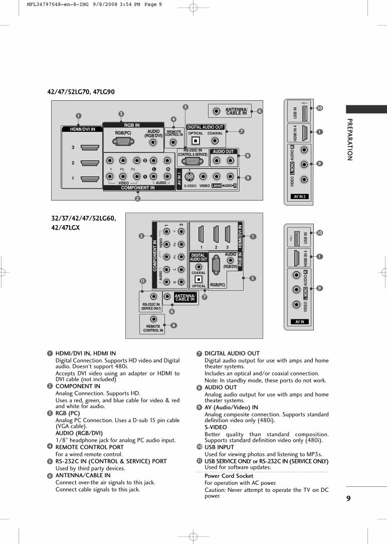
HDMI/DVI IN, HDMI INDigital Connection. Supports HD video and Digitalaudio. Doesn’t support 480i. Accepts DVI video using an adapter or HDMI toDVI cable (not included)COMPONENT INAnalog Connection. Supports HD. Uses a red, green, and blue cable for video & redand white for audio.RGB (PC)Analog PC Connection. Uses a D-sub 15 pin cable(VGA cable).AUDIO (RGB/DVI)1/8” headphone jack for analog PC audio input.REMOTE CONTROL PORTFor a wired remote control.RS-232C IN (CONTROL & SERVICE) PORTUsed by third party devices.ANTENNA/CABLE INConnect over-the air signals to this jack.Connect cable signals to this jack.
DIGITAL AUDIO OUTDigital audio output for use with amps and hometheater systems. Includes an optical and/or coaxial connection.Note: In standby mode, these ports do not work.AUDIO OUTAnalog audio output for use with amps and hometheater systems.AV (Audio/Video) INAnalog composite connection. Supports standarddefinition video only (480i).S-VIDEOBetter quality than standard composition.Supports standard definition video only (480i).USB INPUTUsed for viewing photos and listening to MP3s.USB SERVICE ONLY or RS-232C IN (SERVICE ONLY)Used for software updates.
Power Cord SocketFor operation with AC power. Caution: Never attempt to operate the TV on DCpower.
1 7
8
9
2
3
4
5
6
10
11
AV IN 2
L/M
ONO
RA
UD
IOVI
DEO
HD
MI I
N 4
USB
IN( )
9
10
1
42/47/52LG70, 47LG90
RGB IN
COMPONENT IN
AUDIO(RGB/DVI)
RGB(PC) REMOTECONTROL IN
ANTENNA/CABLE IN
RS-232C IN(CONTROL & SERVICE)
VIDEO AUDIO
OPTICAL COAXIAL
DIGITAL AUDIO OUT
AUDIO OUT
AV
IN 1
R
HDMI/DVI IN
2
3
1
VIDEO MONO( ) AUDIOS-VIDEO
2
1
1 34
6
7
8
2
9
5
32/37/42/47/52LG60,
42/47LGX
AV IN
L/M
ONO
RA
UD
IOVI
DEO
HD
MI I
N 4
USB
IN
9
10
1
(RGB/DVI)
AUDIO
RGB(PC)
REMOTECONTROL IN
RS-232C IN(SERVICE ONLY)
OPTICAL
COAXIAL
DIGITAL AUDIO OUT
R
1 2 3
CO
MP
ON
EN
T IN
21V
IDE
OA
UD
IO
HD
MI/D
VI I
N
RG
B IN
ANTENNA/CABLE IN
2
7
4
1
6
311
MFL34797048-en-8-ING 9/8/2008 3:54 PM Page 9
PR
EPA
RA
TIO
N
10
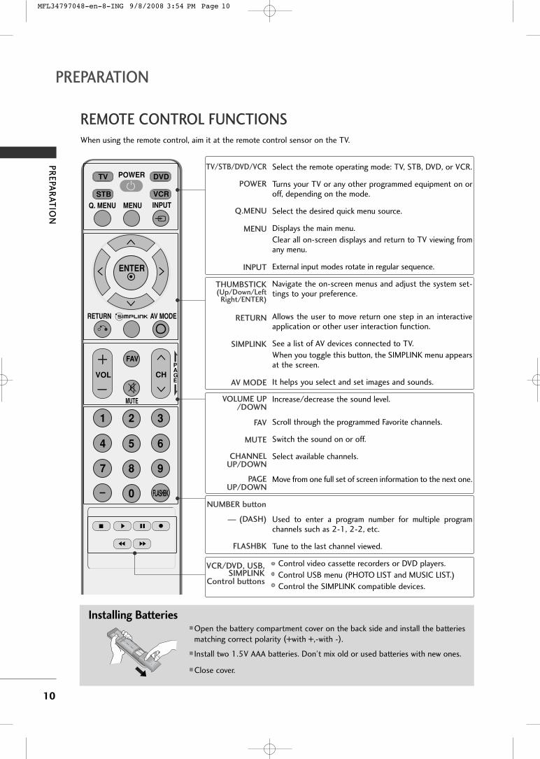
REMOTE CONTROL FUNCTIONS
PREPARATION
When using the remote control, aim it at the remote control sensor on the TV.
INPUT
FAV
MUTE
TV
STB
POWER
Q. MENU MENU
AV MODERETURN
ENTER
VOL CH
1 2 3
4 5 6
7 8
0
9
FLASHBK
PAGE
DVD
VCR
Installing Batteries� Open the battery compartment cover on the back side and install the batteries
matching correct polarity (+with +,-with -).
� Install two 1.5V AAA batteries. Don’t mix old or used batteries with new ones.
� Close cover.
TV/STB/DVD/VCR
POWER
Q.MENU
MENU
INPUT
THUMBSTICK(Up/Down/Left
Right/ENTER)
RETURN
SIMPLINK
AV MODE
VOLUME UP/DOWN
FAV
MUTE
CHANNELUP/DOWN
PAGEUP/DOWN
— (DASH)
FLASHBK
Select the remote operating mode: TV, STB, DVD, or VCR.
Turns your TV or any other programmed equipment on oroff, depending on the mode.
Select the desired quick menu source.
Displays the main menu.Clear all on-screen displays and return to TV viewing fromany menu.
External input modes rotate in regular sequence.
Navigate the on-screen menus and adjust the system set-tings to your preference.
Allows the user to move return one step in an interactiveapplication or other user interaction function.
See a list of AV devices connected to TV.When you toggle this button, the SIMPLINK menu appearsat the screen.
It helps you select and set images and sounds.
Increase/decrease the sound level.
Scroll through the programmed Favorite channels.
Switch the sound on or off.
Select available channels.
Move from one full set of screen information to the next one.
Used to enter a program number for multiple programchannels such as 2-1, 2-2, etc.
Tune to the last channel viewed.
Control video cassette recorders or DVD players.Control USB menu (PHOTO LIST and MUSIC LIST.)Control the SIMPLINK compatible devices.
NUMBER button
VCR/DVD, USB,SIMPLINK
Control buttons
MFL34797048-en-8-ING 9/8/2008 3:54 PM Page 10

PR
EPA
RA
TIO
N
11
STAND INSTRUCTION� Image shown may differ from your TV.
Carefully place the TV screen side down on acushioned surface to protect the screen fromdamage.
Assemble the TV as shown.
Fix the 4 bolts securely using the holes in theback of the TV.
1
2
3
INSTALLATION (Only 42PG25)
Plasma TV models
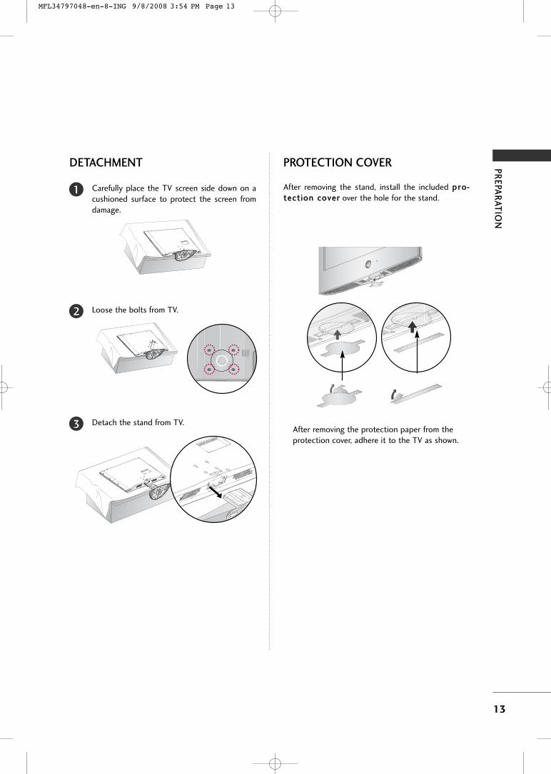
DETACHMENT
Carefully place the TV screen side down on acushioned surface to protect the screen fromdamage.
1
Loose the bolts from TV.2
42PG25 50PG25/60/70 60PG60/70
Detach the stand from TV.3
After removing the stand, install the includedpprrootteeccttiioonn ccoovveerr over the hole for the stand.
Press the PPRROOTTEECCTTIIOONN CCOOVVEERR into the TVuntil you hear it click.
PROTECTION COVER
GG When assembling the desk type stand, make surethe bolt is fully tightened. (If not tightened fully,the TV can tilt forward after the product installa-tion). Do not over tighten.
NOTE!
MFL34797048-en-8-ING 9/8/2008 3:54 PM Page 11

PR
EPA
RA
TIO
N
12
32/37/42/47/52LG60, 42/47LGX
PREPARATION
Assemble the parts of the SSTTAANNDD BBOODDYYwith CCOOVVEERR BBAASSEE of the TV.
2
Assemble the TV as shown.3
Fix the 4 bolts securely using the holes in theback of the TV.
4
Carefully place the TV screen side down on acushioned surface to protect the screen fromdamage.
1
32LG60 37LG60 42LG60, 42LGX
SSTTAANNDD BBOODDYY SSTTAANNDD BBOODDYY
CCOOVVEERR BBAASSEE
SSTTAANNDD BBOODDYY
CCOOVVEERR BBAASSEECCOOVVEERR BBAASSEE
INSTALLATION (Only 32/37/42LG60, 42LGX)
� Image shown may differ from your TV.
GG When assembling the desk type stand, make sure thebolt is fully tightened. (If not tightened fully, the TVcan tilt forward after the product installation). Do notover tighten.
NOTE!
MFL34797048-en-8-ING 9/8/2008 3:54 PM Page 12
PR
EPA
RA
TIO
N
13
DETACHMENT
Carefully place the TV screen side down on acushioned surface to protect the screen fromdamage.
1
Loose the bolts from TV.2
Detach the stand from TV.3
After removing the stand, install the included pprroo--tteeccttiioonn ccoovveerr over the hole for the stand.
After removing the protection paper from theprotection cover, adhere it to the TV as shown.
PROTECTION COVER
MFL34797048-en-8-ING 9/8/2008 3:54 PM Page 13

PR
EPA
RA
TIO
N
14
32/37/42LG30, 37/42/47/52LG50, 32/42/47/52LG70, 47LG90
PREPARATION
� Image shown may differ from your TV.
Assemble the parts of the SSTTAANNDD BBOODDYYwith CCOOVVEERR BBAASSEE of the TV.
2
Assemble the TV as shown.3
Fix the 4 bolts securely using the holes in theback of the TV.
4
SSTTAANNDD BBOODDYY
CCOOVVEERR BBAASSEE
Carefully place the TV screen side down on a cush-ioned surface to protect the screen from damage.
1
INSTALLATION(Only 32/37/42LG30, 37/42LG50, 32/42LG70)
DETACHMENT
Carefully place the TV screen side down on acushioned surface to protect the screen fromdamage.
1
Loose the bolts from TV.2
Detach the stand from TV.3
After removing the stand, install the includedpprrootteeccttiioonn ccoovveerr over the hole for the stand.
Press the PPRROOTTEECCTTIIOONN CCOOVVEERR into the TVuntil you hear it click.
PROTECTION COVER
GG When assembling the desk type stand, make surethe bolt is fully tightened. (If not tightened fully,the TV can tilt forward after the product installa-tion). Do not over tighten.
NOTE!
MFL34797048-en-8-ING 9/8/2008 3:54 PM Page 14

PR
EPA
RA
TIO
N
15
VESA WALL MOUNTINGInstall your wall mount on a solid wall perpendicular to the floor. When attaching to other building materials, pleasecontact your nearest dealer.
If installed on a ceiling or slanted wall, it may fall and result in severe personal injury.
We recommend that you use an LG brand wall mount when mounting the TV to a wall.
LG recommends that wall mounting be performed by a qualified professional installer.
GG Do not install your wall mount kit while your TV is turned on. It may result in personal injury due to electricshock.
CAUTION
GG Screw length needed depends on the wall mountused. For further information, refer to the instruc-tions included with the mount.
GG Standard dimensions for wall mount kits are shownin the table.
GG When purchasing our wall mount kit, a detailedinstallation manual and all parts necessary forassembly are provided.
GG Do not use screws longer then the standard dimen-sion, as they may cause damage to the inside tothe TV.
GG For wall mounts that do not comply with the VESA
standard screw specifications, the length of thescrews may differ depending on their specifica-tions.
GG Do not use screws that do not comply with theVESA standard screw specifications.Do not use fasten the screws too strongly, this maydamage the TV or cause the TV to a fall, leading topersonal injury. LG is not liable for these kinds ofaccidents.
GG LG is not liable for TV damage or personal injurywhen a non-VESA or non specified wall mount isused or the consumer fails to follow the TV installa-tion instructions.
NOTE!
AA
BB
Product Model VESA(A * B) Standard Screw Quantity
32LG30, 32LG60, 32LG70
37LG30, 37LG60, 37LG5042LG30, 42LG50, 42LG60, 42LG70, 42LGX47LG50, 47LG60, 47LG70, 47LG90, 47LGX
52LG50, 52LG60, 52LG70
42PG2550PG25, 50PG60, 50PG70
60PG60, 60PG70
200 * 100
200 * 200
800 * 400
400 * 400
600 * 400
M4
M6
M6
M6
M8
4
4
4
4
4
LCD TV
PLASMA TV
MFL34797048-en-8-ING 9/8/2008 3:54 PM Page 15

PR
EPA
RA
TIO
N
16
PREPARATIONPREPARATION
CABLE MANAGEMENT
Plasma TV Model
Connect the cables as necessary.
To connect additional equipment, see theEXTERNAL EQUIPMENT SETUP section.
Install the CABLE MANAGEMENT CLIP asshown.
If your TV has the CABLE HOLDER, install itas shown and bundle the cables.
1
2
� Here shown may be somewhat different from your TV.
GG Do not hold the CABLE MANAGEMENT CLIP when moving the TV.- If the TV is dropped, you may be injured or the product may be broken.
NOTE!
How to remove the CABLE MANAGEMENT CLIP
GG First, press the cable management. Hold theCCAABBLLEE MMAANNAAGGEEMMEENNTT CCLLIIPP with bothhands and pull it upward.
GG Separate CCAABBLLEE MMAANN--AAGGEEMMEENNTT CCLLIIPP from TVby pressing two latches.
GG Hold the CABLE MAN-
AGEMENT CLIP with bothhands and pull it upward.
42PG25 50PG25, 50/60PG60, 50/60PG70
CABLE MANAGEMENT CLIPCABLE HOLDER
MFL34797048-en-8-ING 9/8/2008 3:54 PM Page 16
PR
EPA
RA
TIO
N
17
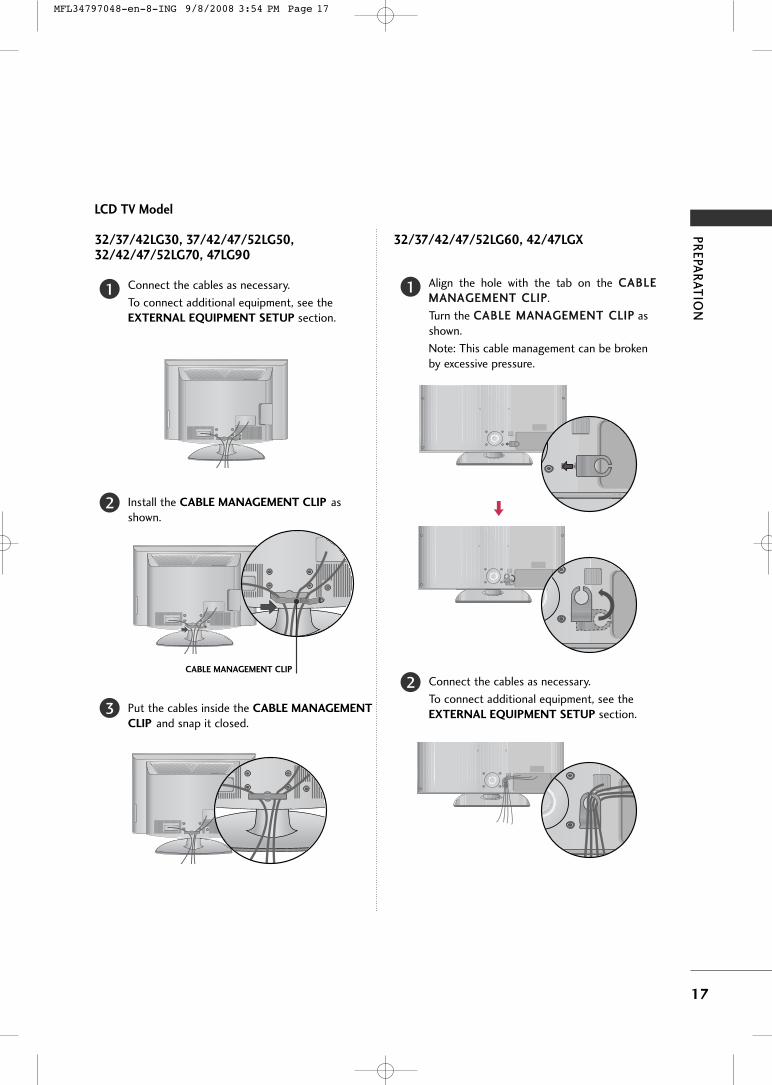
LCD TV Model
Connect the cables as necessary.
To connect additional equipment, see theEXTERNAL EQUIPMENT SETUP section.
Install the CABLE MANAGEMENT CLIP asshown.
CABLE MANAGEMENT CLIP
Align the hole with the tab on the CCAABBLLEEMMAANNAAGGEEMMEENNTT CCLLIIPP.
Turn the CCAABBLLEE MMAANNAAGGEEMMEENNTT CCLLIIPP asshown.
Note: This cable management can be brokenby excessive pressure.
Connect the cables as necessary.
To connect additional equipment, see theEXTERNAL EQUIPMENT SETUP section.Put the cables inside the CABLE MANAGEMENT
CLIP and snap it closed.
32/37/42/47/52LG60, 42/47LGX32/37/42LG30, 37/42/47/52LG50,32/42/47/52LG70, 47LG90
1
2
3
1
2
MFL34797048-en-8-ING 9/8/2008 3:54 PM Page 17
PR
EPA
RA
TIO
N
18
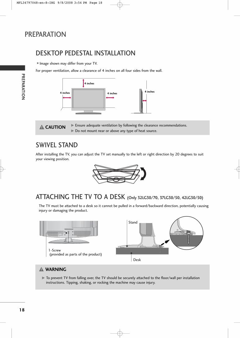
DESKTOP PEDESTAL INSTALLATION
PREPARATION
For proper ventilation, allow a clearance of 4 inches on all four sides from the wall.
� Image shown may differ from your TV.
4 inches
4 inches
4 inches 4 inches
SWIVEL STANDAfter installing the TV, you can adjust the TV set manually to the left or right direction by 20 degrees to suityour viewing position.
GG Ensure adequate ventilation by following the clearance recommendations.
GG Do not mount near or above any type of heat source.CAUTION
ATTACHING THE TV TO A DESK (Only 32LG30/70, 37LG30/50, 42LG30/50)
The TV must be attached to a desk so it cannot be pulled in a forward/backward direction, potentially causinginjury or damaging the product.
GG To prevent TV from falling over, the TV should be securely attached to the floor/wall per installationinstructions. Tipping, shaking, or rocking the machine may cause injury.
WARNING
1-Screw(provided as parts of the product)
Desk
Stand
MFL34797048-en-8-ING 9/8/2008 3:54 PM Page 18

PR
EPA
RA
TIO
N
19
SECURING THE TV TO THE WALL TO PREVENT FALLINGWHEN THE TV IS USED ON A STAND
We recommend that you set up the TV close to a wall so it cannot fall over if pushed backwards.
Additionally, we recommend that the TV be attached to a wall so it cannot be pulled in a forward direction,potentially causing injury or damaging the product.
Caution: Please make sure that children don’t climb on or hang from the TV.
� Insert the eye-bolts (or TV brackets and bolts) to tighten the product to the wall as shown in the picture.
* If your product has the bolts in the eye-bolts position before inserting the eye-bolts, loosen the bolts.
* Insert the eye-bolts or TV brackets/bolts and tighten them securely in the upper holes.
Secure the wall brackets with the bolts (sold separately) to the wall. Match the height of the bracket that ismounted on the wall to the holes in the product.
Ensure the eye-bolts or brackets are tightened securely.
� Use a sturdy rope (sold separately) to tie the product. It is safer to tiethe rope so it becomes horizontal between the wall and the product.
� You should purchase necessary components to prevent TV from falling off of the stand.� Image shown may differ from your TV.
GG Use a platform or cabinet strong enough and large enough to support the size and weight of the TV.GG To use the TV safely make sure that the height of the bracket on the wall and the one on the TV are the same.
NOTE!
Install the power plug closely.
Use of ferrite core
(This feature is not available for all models.)
Ferrite core can be used to reduce the electromagnetic wavewhen connecting the power cord.The closer the location of the ferrite core to the power plug,the better it is.
MFL34797048-en-8-ING 9/8/2008 3:54 PM Page 19

PR
EPA
RA
TIO
N
20
ANTENNA OR CABLE CONNECTION
PREPARATION
1. Antenna (Analog or Digital)
Wall Antenna Socket or Outdoor Antenna without a Cable BoxConnection.
For optimum picture quality, adjust antenna direction if needed.
2. Cable
WallAntennaSocket
OutdoorAntenna(VHF, UHF)
Cable TVWall Jack
Multi-family Dwellings/Apartments(Connect to wall antenna socket)
RF Coaxial Wire (75 ohm)
RF Coaxial Wire (75 ohm)
Single-family Dwellings /Houses(Connect to wall jack for outdoor antenna)
Be careful not to bend the copper wirewhen connecting the antenna.
Copper Wire
� To improve the picture quality in a poor signal area, please purchase a signal amplifier and install properly. � If the antenna needs to be split for two TV’s, install a 2-Way Signal Splitter.� If the antenna is not installed properly, contact your dealer for assistance.
ANTENNA/CABLE IN
( )
R
ANTENNA/CABLE IN
( )
R
� To prevent damage do not connect to the power outlet until all connections are made between the devices.
MFL34797048-en-8-ING 9/8/2008 3:54 PM Page 20
EX
TE
RN
AL E
QU
IPM
EN
T S
ET
UP
21
EXTERNAL EQUIPMENT SETUP
HD RECEIVER SETUP
This TV can receive Digital Over-the-air/Cable signals without an external digital set-top box. However, if you do
receive digital signals from a digital set-top box or other digital external device, refer to the figure as shown below.
Component Connection
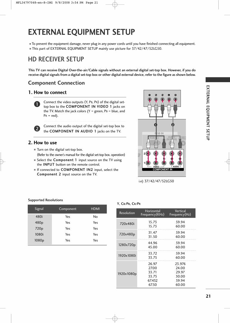
1. How to connect
Connect the video outputs (Y, PB, PR) of the digital set-top box to the CCOOMMPPOONNEENNTT IINN VVIIDDEEOO 11 jacks onthe TV. Match the jack colors (Y = green, PB = blue, andPR = red).
Connect the audio output of the digital set-top box to
the CCOOMMPPOONNEENNTT IINN AAUUDDIIOO 11 jacks on the TV.
2. How to use� Turn on the digital set-top box.
(Refer to the owner’s manual for the digital set-top box. operation)
� Select the CCoommppoonneenntt 11 input source on the TV usingthe IINNPPUUTT button on the remote control.
� If connected to CCOOMMPPOONNEENNTT IINN22 input, select theCCoommppoonneenntt 22 input source on the TV.
� To prevent the equipment damage, never plug in any power cords until you have finished connecting all equipment.� This part of EXTERNAL EQUIPMENT SETUP mainly use picture for 37/42/47/52LG50.
Y, CB/PB, CR/PR
Supported Resolutions
Horizontal Vertical Frequency(KHz) Frequency(Hz)
15.73 59.9415.73 60.00
31.47 59.9431.50 60.00
44.96 59.9445.00 60.00
33.72 59.9433.75 60.00
26.97 23.97627.00 24.0033.71 29.9733.75 30.0067.432 59.9467.50 60.00
Resolution
720x480i
720x480p
1280x720p
1920x1080i
1920x1080p
Signal
480i
480p
720p
1080i
1080p
Component
Yes
Yes
Yes
Yes
Yes
HDMI
No
Yes
Yes
Yes
Yes
2
1
RGB INAUDIO
(RGB/DVI)RGB(PC) REMOT
CONTROL
(
COMPONENT IN
1
2
VIDEO
LY PB PR R
AUDIO
Y L RPB PR
1 2
i.e) 37/42/47/52LG50
MFL34797048-en-8-ING 9/8/2008 3:54 PM Page 21

EX
TE
RN
AL E
QU
IPM
EN
T S
ET
UP
22
EXTERNAL EQUIPMENT SETUP
DVD SETUP
HDMI Connection
Connect the HDMI output of the DVD to theHHDDMMII//DDVVII IINN11, 22, 33 or 44 jack on the TV.
No separate audio connection is necessary.
HDMI supports both audio and video.
1. How to connect
2. How to use
� Select the HHDDMMII11, HHDDMMII22, HHDDMMII33, or HHDDMMII44 inputsource on the TV using the IINNPPUUTT button on the remotecontrol.
� Refer to the DVD player's manual for operating instructions.
2
1
Component Connection
Connect the video outputs (Y, PB, PR) of the DVD to theCCOOMMPPOONNEENNTT IINN VVIIDDEEOO11 jacks on the TV.
Match the jack colors (Y = green, PB = blue, and PR = red).
Connect the audio outputs of the DVD to the
CCOOMMPPOONNEENNTT IINN AAUUDDIIOO11 jacks on the TV.
1. How to connect
2. How to use
� Turn on the DVD player, insert a DVD.� Select the CCoommppoonneenntt 11 input source on the TV using
the IINNPPUUTT button on the remote control.� If connected to CCOOMMPPOONNEENNTT IINN 22 input, select the
CCoommppoonneenntt 22 input source on the TV.� Refer to the DVD player's manual for operating instructions.
2
1
RGB INAUDIO
(RGB/DVI)RGB(PC) REMOT
CONTRO
COMPONENT IN
1
2
VIDEO
LY PB PR R
AUDIO
Y L RPB PR
1 2
COMPONENT IN
U O(RGB/D
RGB(PC)
1
2
VIDEO
LY PB PR
A
HDMI/DVI IN
2
1
HDMI-DVD OUTPUT
1
i.e) 37/42/47/52LG50
i.e) 37/42/47/52LG50
MFL34797048-en-8-ING 9/8/2008 3:54 PM Page 22

EX
TE
RN
AL E
QU
IPM
EN
T S
ET
UP
23
VCR SETUP
Composite (RCA) Connection
GG If you have a mono VCR, connect the audio cable fromthe VCR to the AAUUDDIIOO LL//MMOONNOO jack of the TV.
NOTE!
NT IN
AUDIO(RGB/DVI)
REMOTECONTROL IN
ANTENNA/CABLE IN
RS-232C IN(CONTROL & SERVICE)
L R
AUDIO
OPTICAL COAXIAL
DIGITAL AUDIO OUT
AUDIO OUT
AV
IN 1
VIDEO L R(MONO) AUDIOS-VIDEO
L RS-VIDEO VIDEO
OUTPUTSWITCH
ANT IN
ANT OUT
1
Connect the AAUUDDIIOO/VVIIDDEEOO jacks between TV andVCR. Match the jack colors (Video = yellow, Audio Left= white, and Audio Right = red)
1. How to connect
2. How to use
� Insert a video tape into the VCR and press PLAY on the VCR.(Refer to the VCR owner’s manual.)
� Select the AAVV11 input source on the TV using the IINNPPUUTTbutton on the remote control.
� If connected to AAVV IINN22, select AAVV22 input source on the TV.
GG Do not connect to both Video and S-Video at the sametime. In the event that you connect both Video and theS-Video cables, only the S-Video will work.
CAUTION
GG S-Video provides better quality than composite. Use itwhen available.
NOTE!
S-Video Connection (Except 32/37/42/47/52LG60, 42/47LGX)
NT IN
AUDIO(RGB/DVI)
REMOTECONTROL IN
ANTENNA/CABLE IN
RS-232C IN(CONTROL & SERVICE)
L R
AUDIO
OPTICAL COAXIAL
DIGITAL AUDIO OUT
AUDIO OUT
AV
IN 1
VIDEO L R(MONO) AUDIOS-VIDEO
L RS-VIDEO VIDEO
OUTPUTSWITCH
ANT IN
ANT OUT
1 2
Connect the S-VIDEO output of the VCR to theSS --VVIIDDEEOO input on the TV.
Connect the audio outputs of the VCR to the AAUUDDIIOOinput jacks on the TV.
1. How to connect
2. How to use
� Insert a video tape into the VCR and press PLAY on the VCR.(Refer to the VCR owner’s manual.)
� Select the AAVV11 input source on the TV using the IINNPPUUTTbutton on the remote control.
i.e)
i.e)
1
1
2
MFL34797048-en-8-ING 9/8/2008 3:54 PM Page 23

EX
TE
RN
AL E
QU
IPM
EN
T S
ET
UP
24
EXTERNAL EQUIPMENT SETUP
PC SETUP
Connect the VGA output of the PC to the RRGGBB ((PP CC))jack on the TV.
Connect the PC audio output to the AAUUDDIIOO((RRGGBB//DDVVII)) jack on the TV.
1. How to connect
2. How to use
� Turn on the PC and the TV.� Select the RRGGBB--PPCC input source on the TV using the
IINNPPUUTT button on the remote control.
2
1
VGA (D-Sub 15 pin) Connection
COMPONENT IN
REMOTECONTROL IN
1
2(CO
VIDEO
LY PB PR R
AUDIO
I IN
RGB INAUDIO
(RGB/DVI)RGB(PC)
RGB OUTPUT AUDIO
1 2
Horizontal Vertical Frequency(KHz) Frequency(Hz)
31.469 70.08
31.469 70.08
31.469 59.94
37.879 60.31
48.363 60.00
47.776 59.87
47.720 59.799
47.130 59.65
Resolution
720x400
1360x768
640x350
640x480
800x600
1024x768
1280x768
1366x768
Supported Display Specifications (RGB-PC, HDMI-PC)
For 32/37/42LG30 For 37/42/47/52LG50, 32/37/42/47/52LG60,32/42/47/52LG70, 42/47LGX, 47LG90,42/50PG25, 50/60PG60, 50/60PG70
* Only RGB-PC mode
Resolution
640x350
Horizontal Vertical Frequency(KHz) Frequency(Hz)
31.468 70.0931.469 70.0831.469 59.9437.500 75.0037.861 72.8035.156 56.2537.879 60.3146.875 75.0048.077 72.1848.363 60.0056.476 70.0660.023 75.0247.776 59.8760.289 74.89363.981 60.0279.976 75.02547.712 60.01575.00 60.0066.587 59.934
67.5 60.00
66.587 59.934
* Only RGB-PC mode
720x400
1360x768
640x480
800x600
1024x768
1280x1024
1600x1200
LCD TV1920x1080
Plasma TV1920x1080
RGB-PC
HDMI-PC
1280x768
i.e) 37/42/47/52LG50
MFL34797048-en-8-ING 9/8/2008 3:54 PM Page 24

WA
TC
HIN
G T
V
25
WATCHING TV
TURNING ON TV
CHANNEL SETUP
NOTE! GG If you intend to be away on vacation, disconnect the power plug from the wall power outlet.
First, connect power cord correctly.
At this moment, the TV switches to standby mode.� In standby mode to turn TV on, press the , IINNPPUUTT, ((DDEE or )) button on the TV or press the PPOOWWEERR,
IINNPPUUTT, CCHH(( or )), NNuummbbeerr ((00~99)) button on the remote control.
Select the viewing source by using the IINNPPUUTT button on the remote control.� This TV is programmed to remember which power state it was last set to, even if the power cord is out.
When finished using the TV, press the PPOOWWEERR button on the remote control. The TV reverts to standby mode.
1
2
3
Auto Scan (Auto Tuning)
Automatically finds all channels available through antenna or cable inputs, and stores them in memory on the
channel list.
Run Auto Tuning again after any Antenna/Cable connection changes.
Select CCHHAANNNNEELL.
Select AAuuttoo TTuunniinngg.
Select YYeess.
Run AAuuttoo ttuunniinngg.
1MENU
3
2ENTER
ENTER
4ENTER
� A password is required to gain access toAuto Tuning menu if the Lock System isturned on.
5RETURN
Return to the previous menu.
MENUReturn to TV viewing.
EnterMoveCHANNEL EnterMoveCHANNEL
Auto Tuning
Manual Tuning
Channel Edit
Auto Tuning
Manual Tuning
Channel Edit
Press ‘Yes’ button to beginauto tuning.
Yes
No
MFL34797048-en-8-ING 9/8/2008 3:54 PM Page 25

WA
TC
HIN
G T
V
26
WATCHING TV
INITIAL SETTING
This Function guides the user to easily set the essential items for viewing the TV for the first time when
purchasing the TV. It will be displayed on the screen when turning the TV on for the first time. It can also be
activated from the user menus.
Select HHoommee Mode.1
2ENTER
Select AAuuttoo or MMaannuuaall.
Select desired time option.
1
3ENTER
2
Year
Current Time Setting
2007
Month 11
Date 15
Hour 5 PM
Minute 52
Time Zone Eastern
Daylight Saving Off
FF Auto GG
ExitEnter RETURN
Step2. Time Setting
Selecting the environment.Choose the setting mode you want.
In Store Home
ExitEnter RETURN
Step1. Mode Setting
Step1. Mode Setting
Step2. Time Setting
� Default selection is “HHoommee”. We recommend setting the TV to “HHoommee” mode for the best picture in yourhome environment.
� “IInn--ssttoorree” Mode is only intended for use in retail environments. Customers can adjust the “PPiiccttuurree menu- PPiiccttuurree mmooddee” manually while inspecting the TV, but the TV will automatically return to preset in-storemode after 5 minutes.
� “IInn--ssttoorree” Mode is an optimal setting for displaying at stores. “In-Store” mode initializes the TV to set theimage quality and operates “TTrruuMMoottiioonn DDeemmoo (For 37/42/47/52LG60, 42/47/52LG70, 42/47LGX)”or “LLooccaall DDiimmmmiinngg DDeemmoo (For 47LG90)” after a certain period of time.
!
Select OOSSDD LLaanngguuaaggee SSeettttiinngg orAAuuddiioo LLaanngguuaaggee SSeettttiinngg.
Start AAuuttoo TTuunniinngg.
Select your desired language.
1
3ENTER
1ENTER
2
Auto Tuning can change channel map.Do you want to start Auto Tuning?
Enter
ExitEnter RETURN
Step4. Auto Tuning
ExitEnter RETURN
Step3. Option Setting
1. OSD Language Setting FF English GG
2. Audio Language Setting French
Step3. Option Setting
Step4. Auto Tuning
� You can also adjust IInniitt iiaall SSeettttiinngg in theOOPPTTIIOONN menu.
NOTE!
MFL34797048-en-8-ING 9/8/2008 3:54 PM Page 26

WA
TC
HIN
G T
V
27
QUICK MENU
ON-SCREEN MENUS SELECTION
Q.Menu (Quick Menu) is a menu of features which users might use frequently.
Display each menu.
Select a menu item.
Enter to the pop up menu.
1MENU
3
2ENTER
ENTER
Return to TV viewing.4
MENU
Your TV's OSD (On Screen Display) may differ slightly from that shown in this manual.
� All available TV channels are searched and storedautomatically.
� User can do manual channel selection and add ordelete individual channels.
� You can add or delete in the channel list.Channel Edit
Manual Tuning
Auto Tuning
LCD TV
Q.Menu
3
FF 16:9 GG
Vivid
Off
Standard
Off
English
Off
Add
Eject
Aspect Ratio
Backlight
Clear Voice
Picture Mode
Sound Mode
Caption
Multi Audio
Sleep Timer
Del/Add/Fav
USB Eject
CH
Plasma TV
Q.Menu
Close Close
3
FF 16:9 GG
Vivid
Off
Standard
Off
English
Off
Add
Eject
Aspect Ratio
Power Saving
Clear Voice
Picture Mode
Sound Mode
Caption
Multi Audio
Sleep Timer
Del/Add/Fav
USB Eject
CH
Except 32/37/42LG30
Display each menu.
Make appropriate adjustments.
Return to TV viewing.
1Q. MENU
3
2
Q. MENU
CHANNEL
ENTERMove
Auto Tuning
Manual Tuning
Channel Edit
CHANNEL
CHANNEL
OPTION
PICTURE
LOCK
AUDIO
INPUT
TIME
USB
CHANNEL
TIME
PICTURE
OPTION
AUDIO
LOCK
or
MFL34797048-en-8-ING 9/8/2008 3:54 PM Page 27

WA
TC
HIN
G T
V
28
WATCHING TV
PICTURE
AUDIO
� Select the desired picture format: Set by program,4:3, 16:9, Zoom1, Zoom2, Just Scan.
� Select the Intelligent Sensor (Except 32/37/42LG30,Plasma TV), Vivid, Standard, Cinema/ Cinema(Only for 50/60PG60/70), Sport, Game, Expert1, Expert2.
� Adjust the Backlight (Only LCD TV), Contrast,Brightness, Sharpness, Color, Tint.
� Advanced Control: Adjust the Color Temperature, FreshContrast, Fresh Color, Noise Rreduction, Gamma, ColorGamut (Only 47LG90), Black Level, Eye Care (Only LCDTV), Real Cinema (For LCD TV) / Film Mode (For PlasmaTV), TruMotion (Only 37/42/47/52LG60, 42/47LGX,47LG90, 42/47/52LG70).
� Reset: Settings of the selected picture modes returnto the default factory settings.
� Adjust the screen Resolution, Auto config, Position,Size, Phase, Reset.
� Use this feature to see the difference TruMotion makes.(37/42/47/52LG60, 42/47/52LG70, 42/47LGX, 47LG90 Only)
� After analyzing the signal of the input video by areasof the screen, it adjusts the brightness to improvethe contrast ratio.
� Use this feature to see Local Dimming Demo.
Picture Mode
Aspect Ratio
Screen (RGB-PC)
TruMotion Demo
Local Dimming(47LG90 only)
Local Dimming Demo(47LG90 only)
� Auto Volume makes sure that the volume levelremains consistent whether you are watching acommercial or a regular TV program.
� By differentiating the human sound range from others,it helps users listen to human voices better.
� Adjust the left/right sound of speaker.
� Select the Standard, Music, Cinema, Sport, and Game.
� SRS TruSurround XT, Treble, Bass: Adjust the soundto suit your taste and room situations.
� Reset: Settings of the selected Sound Mode returnto the default factory settings.
� Turn the TV speaker On or off.
Balance
TV Speaker
Auto Volume
Sound Mode
Clear Voice
� Auto: The time is set automatically from a digitalchannel signal.Select your viewing area time zone.Select Auto, Off, On depending on whether ornot your viewing area observes Daylight Savingtime.
� Manual: Set the clock manually.
� Select On or Off.
� Select On or Off.
� Select the amount of time before your TV turns offautomatically: Off, 10, 20, 30, 60, 90, 120, 180, 240.
� TV will be automatically turned off, in case of nosignal for 10 minutes.
Off Time
On Time
Sleep Timer
Clock
Auto Sleep
TIME
EnterMovePICTURE
E
Aspect Ratio : 16:9
Picture Mode : Standard
• Backlight 80
• Contrast 90
• Brightness 50
• Sharpness 60
• Color 60
• Tint 0 R G
EnterMoveAUDIO
E
L R
Auto Volume : Off
Clear Voice : On
Balance 0
Sound Mode : Standard
• SRS TruSurround XT: Off
• Treble 50
• Bass 50
• Reset
EnterMoveTIME
Clock : Feb/21/2008 2:10 AM
Off Time : Off
On Time : Off
Sleep Timer : Off
Auto Sleep : Off
MFL34797048-en-8-ING 9/8/2008 3:54 PM Page 28

WA
TC
HIN
G T
V
29
OPTION� Select your desired language for on screen menus
: English, Spanish, French.� Set a label to each input source.� Control and play other AV devices connected to the TV
through HDMI cable without additional cables and settings.� This feature can be used to prevent unauthorized
viewing by locking out the front panel controls.� When selecting Off, Submenus for Analog, DTV, and
Digital Option become disabled.� Analog: CC1~ CC4 , Text1~ Text4.� Digital: CC1~ CC4 , Text1~ Text4, Service1~ Service6.� Digital Option: Customize the DTV/CADTV captions
that appear on your screen.� Use it to minimize any fixed image on the screen.
: Normal, Orbiter, Inversion, White Wash.� Reduces the plasma display power consumption.
� Choose the desired TV ID number.
� Adjust Power Indicator menu options.
� After turning on the TV, adjust Mode, Time, Language,Auto Tuning.
SIMPLINK
key Lock
ISM Method(Plasma TV only)
Power Saving(Plasma TV only)
Caption
Input Label
Language
� Select On or Off.
� Change the password.
� Select a channel number that you wish to block.
� Blocks movies according to the movie ratings limitsspecified.
� Prevents children from watching certain children'sTV programs, according to the ratings limit set.
� Based on the ratings, blocks certain TV programsthat you and your family do not want to view.
� Selecting canadian english language rating system.
� Selecting canadian french language rating system.
� This function may become available in the future andwill be available only for digital channel signal.
� Enables you to select a source to block from theexternal source devices you have hooked up.
Block Channel
Movie Rating
TV Rating-Children
TV Rating-General
TV Rating-English
TV Rating-French
DownloadableRating
Input Block
Set Password
Lock System
For USA
LOCK Initial Setting
Power Indicator(LCD TV only)
Set ID (Except 42/47LGX,
32/37/42/47/52LG60)
For Canada
EnterMove
Lock System : Off
Set Password
Block Channel
TV Rating-English
TV Rating-French
Downloadable Rating
Input Block
LOCK
EnterMove
Lock System : Off
Set Password
Block Channel
Movie Rating
TV Rating-Children
TV Rating-General
Downloadable Rating
Input Block
LOCK
EnterMove
Antenna
Cable
AV1
AV2
Component1
Component2
RGB-PC
HDMI1
INPUT
E
INPUT USB
� Select desired inputsources.
� Your TV's OSD (OnScreen Display) maydiffer slightly from thatshown in this manual.
Input
(Except 32/37/42LG30)
� Use PHOTO LIST orMUSIC LIST.
USB
(Except 32/37/42LG30)
EnterMove
PHOTO LIST
MUSIC LIST
USB
EnterMoveOPTION
E
Language : English
Input Label
SIMPLINK : On
Key Lock : Off
Caption : Off
ISM Method : Normal
Power Saving : Level 0
Set ID : 1
MFL34797048-en-8-ING 9/8/2008 3:54 PM Page 29
US
B
30
ENTRY MODES
USB
When you connect a USB device, this screen is displayed automatically.
In USB device, you can not add a new folder or delete the existing folder.
Precautions when using the USB device
GG Only a USB storage device is recognizable.
GG If the USB storage device is connected through aUSB hub, the device is not recognizable.
GG A USB storage device using an automatic recogni-tion program may not be recognized.
GG A USB storage device which uses its own drivermay not be recognized.
GG In case of a card reader, up to four memory cardsare concurrently recognizable.
GG The recognition speed of a USB storage devicemay depend on each device.
GG Please do not turn off the TV or unplug the USBdevice when the connected USB storage device isworking. When such device is suddenly separatedor unplugged, the stored files or the USB storagedevice may be damaged.
GG Please do not connect the USB storage devicewhich was artificially maneuvered on the PC. Thedevice may cause the product to malfunction orfail to be played. Never forget to use only a USBstorage device which has normal music files orimage files.
GG Please use only a USB storage device which wasformatted as a FAT or NTFS file system providedwith the Windows operating system. In case of astorage device formatted as a different utility pro-gram which is not supported by Windows, it maynot be recognized.
GG Please connect power to a USB storage devicewhich requires an external power supply. If not,the device may not be recognized.
GG Please connect a USB storage device with cable isoffered by USB maker. If connected with cable isnot offered by USB maker or an excessively longcable, the device may not be recognized.
GG Some USB storage devices may not be supportedor operated smoothly.
GG File alignment method of USB storage device issimilar to Window XP and filename can recognizeup to 100 English characters.
GG Please backup important files because data onUSB device may be damaged. Data management isconsumer's responsibility and as a result, the man-ufacturer does not cover data damage.
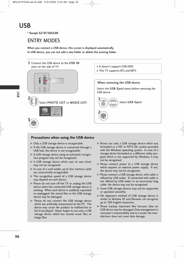
Connect the USB device to the UUSSBB IINNjacks on the side of TV.
3
Select PPHHOOTTOO LLIISSTT or MMUUSSIICC LLIISSTT.
1
DM
I IN
3U
SB IN
PHOTO LIST MUSIC LIST
2
ENTER
* Except 32/37/42LG30
When removing the USB device
Select UUSSBB EEjjeecctt.
Select the UUSSBB EEjjeecctt menu before removing theUSB device.
1Q. MENU
2ENTER
� It doesn’t support USB HDD� This TV supports JPG and MP3.
MFL34797048-en-8-ING 9/8/2008 3:54 PM Page 30

US
B
31
PHOTO LISTYou can view .JPG files from USB storage devices.
The On Screen Display on your model may be slightly different.
Photo Selection and Popup Menu
� Use the CCHH button to navigation in thephoto page.
� Use the FFAAVV button to mark or unmark a photo.When one or more photos are marked, you canview individual photos or a slide show of themarked photos. If no photos are marked, you canview all photos individually or all photos in thefolder in a slide show.
Screen Components
Moves to upper level file
Preview: Display the
thumbnail/folder name of
the photo in the selected
folder
Current page/Total pages
Total number of marked photos
Usable USB memory
Corresponding buttons on
the remote control
USB Device
Page 1/1 No MarkedPHOTO LIST
Upper
Free Space 150MB
Navigate PopUp Menu Move Page Mark Exit
2Folders, 4Files
3 4 5
1
2
Select UUSSBB. Select PPHHOOTTOO LLIISSTT.2
TOP FOLDER
Drive1
1MENU
ENTER ENTER
1
2
3
4
5
6
Drive1
CH FAV RETURN
6
1
Select the target folder or drive.
Select the desired photos.2
Show the Popup menu.3
1
4 Select the desired Popup menu.
ENTER
ENTER
ENTER
USB Device
Page 1/1 No MarkedPHOTO LIST
Upper
Free Space 150MB
2Folders, 4Files
USB Device
Page 1/1 No MarkedPHOTO LIST
Upper
Free Space 150MB
1366x768 125KB
TOP FOLDERDrive1
Navigate Move Page Mark ExitCH FAV RETURNPopUp Menu
Navigate Move Page Mark ExitCH FAV RETURNPopUp Menu
Drive1
Drive1Butterfly
Upper Photo X.Box1366x768125KB
View
Mark All
Delete
Cancel
When you select a file (not folder), this PopUpmenu is displayed.
GG VViieeww: Display the selected item.
GG MMaarrkk AAllll: Mark all photos on the screen.
GG UUnnmmaarrkk AAll ll: Deselect all marked photos.
GG DDeelleettee: Delete the selected photo item.
GG CCaanncceell: Close the pop-up menu.
MFL34797048-en-8-ING 9/8/2008 3:54 PM Page 31

US
B
32
USB
Full Screen Menu
You can change the Photo List view so that it fills the
screen. More operations are available in full screen mode.
Select the target folder or drive.
Select the desired photos.
Show the Popup menu.
5
Select VViieeww.
The selected photo is displayed infull size.
2
3
1
4
ENTER
ENTER
ENTER
Select the SSiiddeesshhooww, BBGGMM, ((RRoottaattee)),DDeelleettee, OOppttiioonn, or HHiiddee..
Press FF GG to set the time interval between slides.
Slide Speed Fast
Cancel
...Music Folder
ENTER
ENTER
6
USB Device
Page 1/1 No MarkedPHOTO LIST
Upper
Free Space 150MB
2Folders, 4Files
USB Device
Page 1/1 No MarkedPHOTO LIST
Upper
Free Space 150MB
1366x768 125KB
TOP FOLDERDrive1
Navigate Move Page Mark ExitCH FAV RETURNPopUp Menu
Navigate Move Page Mark ExitCH FAV RETURNPopUp Menu
Drive1
Drive1Butterfly
Upper Photo X.Box1366x768125KB
View
Mark All
Delete
Cancel
The aspect ratio of a photo may change the size ofthe photo displayed on the screen in full size.
1/17
Sideshow BGM Delete Option Hide
GG SSiiddeesshhooww: Selected photos are displayed during theslide show. If no photo is selected, all photos in the cur-rent folder are displayed during slide show.� Set the time interval of the slide show in OOppttiioonn.� A slide show continues for a maximum of 4 hours.
After 4 hours, the slide show will end and go to TVmode or external input mode.
GG BBGGMM: Listen to music while viewing photos in full size. � Set the BGM device and album in OOppttiioonn.
GG ((RRoottaattee)): Rotate photos.� Rotates the photo 90°, 180°, 270°, 360° clockwise.
GG DDeelleettee: Delete photos.
GG OOppttiioonn: Set values for SSll iiddee SSppeeeedd and MMuussiiccFFoollddeerr. � Use button and EENNTTEERR button to set values.
Then go to and press EENNTTEERR to save the set-tings.
� You cannot change MMuussiicc FFoollddeerr while BGM isplaying.
GG HHiiddee : Hide the menu on the full-sized screen.� To see the menu again on the full-sized screen, press
EENNTTEERR button to display.
NOTE!
GG This TV will not be able to decodemost JPG images saved using theProgressive option.
MFL34797048-en-8-ING 9/8/2008 3:54 PM Page 32
US
B
33
MUSIC LISTYou can use the Music List menu to play MP3 files form a USB storage device.
This TV cannot play back copy-protected files.
The On Screen Display on your model may be slightly different.
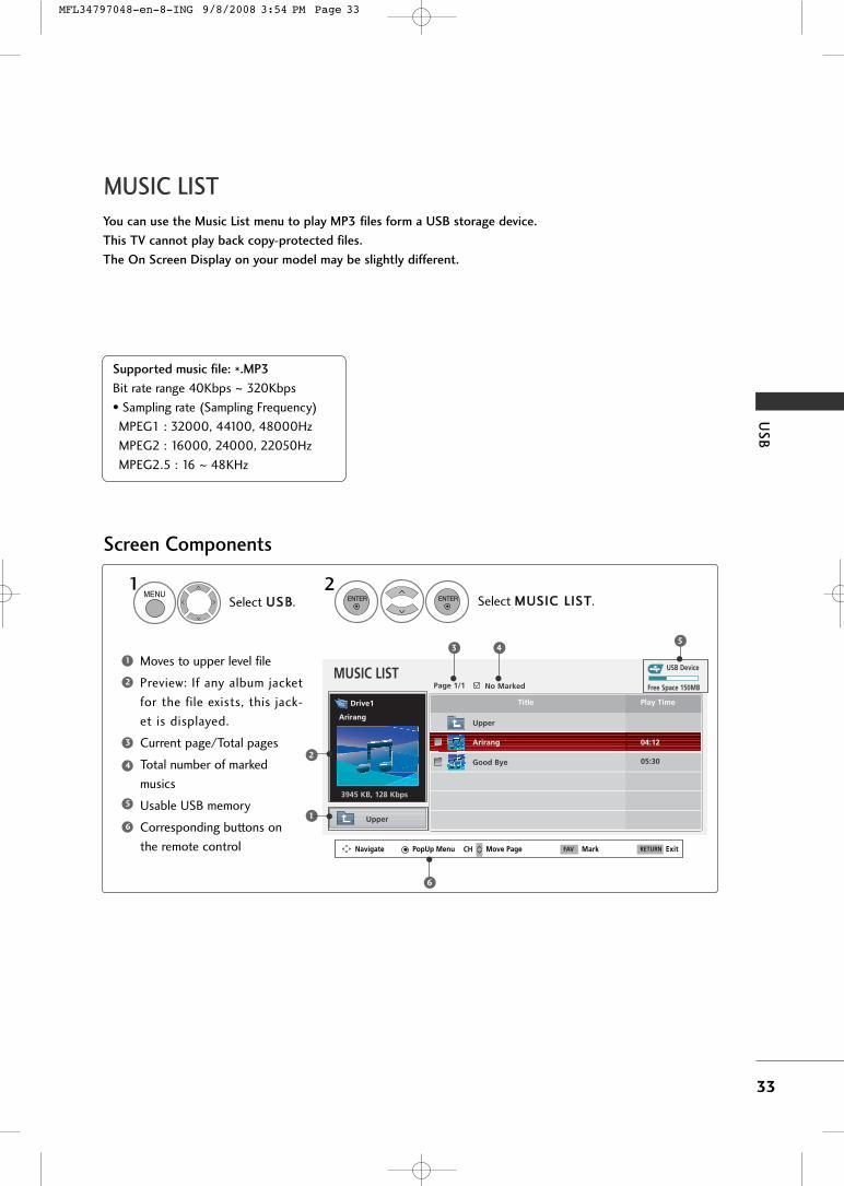
Screen Components
Supported music file: *.MP3
Bit rate range 40Kbps ~ 320Kbps
• Sampling rate (Sampling Frequency)
MPEG1 : 32000, 44100, 48000Hz
MPEG2 : 16000, 24000, 22050Hz
MPEG2.5 : 16 ~ 48KHz
Moves to upper level file
Preview: If any album jacket
for the file exists, this jack-
et is displayed.
Current page/Total pages
Total number of marked
musics
Usable USB memory
Corresponding buttons on
the remote control
1
3
4
5
6
2
Select UUSSBB. Select MMUUSSIICC LLIISSTT.1 2
MENUENTER ENTER
USB DeviceMUSIC LIST
Upper
Free Space 150MB
3945 KB, 128 Kbps
Title Play Time
Upper
Good Bye
Arirang 04:12
05:30
35
1
2
Navigate PopUp Menu Move Page Mark ExitCH FAV RETURN
6
Page 1/1 No Marked
Drive1
Arirang
4
MFL34797048-en-8-ING 9/8/2008 3:54 PM Page 33

US
B
34
USB
Music Selection and Popup Menu
GG PPllaayy (During stop): Play the selected music.
Once a song finishes playing, the next selectedone will be played. When there are no selectedmusics to play, the next one in the current fold-er will be played. If you go to a different folderand press the EENNTTEERR button, the currentmusic in playback will stop.
GG PPllaayy MMaarrkkeedd: Play the selected musics. Oncea music finishes playing, the next selected onewill be played automatically.
GG SSttoopp PPllaayy (During playback): Stop the play-ing musics.
GG PPllaayy wwiitthh PPhhoottoo: Start playing the selectedmusics and then move to the Photo List.
GG MMaarrkk AAll ll: Mark all musics in the folder.
GG UUnnmmaarrkk AAll ll: Deselect all marked music.
GG DDeelleettee: Delete the selected music.
GG CCaanncceell: Close the pop-up menu.
� Use the CCHH button to navigation inthe music page.
� Use FFAAVV button to mark or unmark a musicfile. If no music is marked, all the music in thefolder will be played in sequence. When one ormore music files are marked, the marked musicfiles will be played in sequence. If you want tolisten to only one song repeatedly, just markthat one file and play.
Select the target folder or drive.
Select the desired musics.
show the PopUp menu.
Select the desired PopUp menu.
2
3
1
4
ENTER
ENTER
ENTER
Up to 6 music titles are listed per page.
5RETURN Return to TV viewing.
� The play information box (as shown below) willautomatically move across the screen when thereis no user input to prevent a fixed image remain-ing on the screen for a extended period of time.
NOTE!
GG When music is playing, is displayed in front of the music play time.
GG A damaged or corrupted music file that does not play displays 00:00 as the play time.
GG Music files with copy-protection will not play.
GG Press EENNTTEERR, AA , or RREETTUURRNN button to stop the screen saver.
GG This TV can not play music files less than 16 Kbytes.
USB Device
Page 1/1 No MarkedMUSIC LIST
Upper
Free Space 150MB
3945 KB, 128 Kbps
Drive1
Arirang
Navigate Move Page Mark ExitCH FAV RETURNPopUp Menu
Play TimeTitle
Upper
Good Bye
Arirang
USB Device
Page 1/1 No MarkedMUSIC LIST
Upper
Free Space 150MB
3945 KB, 128 Kbps
Drive1
Arirang
Navigate Move Page Mark ExitCH FAV RETURNPopUp Menu
Play TimeTitle
Upper
Good Bye
Arirang
05:30
04:12
3945 KB128 Kbps
Play
Play with Photo
Mark All
Delete
Cancel
MFL34797048-en-8-ING 9/8/2008 3:54 PM Page 34

AP
PE
ND
IX
35
TROUBLESHOOTING
APPENDIX
TThhee ooppeerraattiioonn ddooeess nnoott wwoorrkk nnoorrmmaallllyy..
TThhee vviiddeeoo ffuunnccttiioonn ddooeess nnoott wwoorrkk..
No picture &No sound
No or poor color
or poor picture
Poor reception on
some channels
Lines or streaks
in pictures
No picture
when connecting HDMI
Horizontal/vertical bars
or picture shaking
Picture appears slowly
after switching on
The remote control
doesn’t work
Power is suddenly
turned off
� Check to see if there is any object between the product and the remote controlcausing obstruction. Ensure you are pointing the remote control directly at the TV.
� Ensure that the batteries are installed with correct polarity (+ to +, - to -).� Ensure that the correct remote operating mode is set: TV, VCR etc.� Install new batteries.
� Is the sleep timer set?� Check the power control settings. Power interrupted.
� Check whether the product is turned on.� Try another channel. The problem may be with the broadcast.� Is the power cord inserted into wall power outlet?� Check your antenna direction and/or location.� Test the wall power outlet, plug another product’s power cord into the outlet
where the product’s power cord was plugged in.
� This is normal, the image is muted during the product startup process. Pleasecontact your service center, if the picture has not appeared after five minutes.
� Adjust Color in menu option.� Keep a sufficient distance between the product and the VCR.� Try another channel. The problem may be with the broadcast.� Are the video cables installed properly?� Activate any function to restore the brightness of the picture.
� Check for local interference such as an electrical appliance or power tool.
� Station or cable product experiencing problems, tune to another station.� Station signal is weak, reorient antenna to receive weaker station.� Check for sources of possible interference.
� Check antenna (Change the direction of the antenna).
� Check HDMI cable over version 1.3.
The HDMI cables don’t support HDMI version 1.3, it cause flickers or no screendisplay. In this case use the latest cables that support HDMI version 1.3.
MFL34797048-en-8-ING 9/8/2008 3:54 PM Page 35

AP
PE
ND
IX
36
APPENDIX
TThheerree iiss aa pprroobblleemm iinn PPCC mmooddee.. ((OOnnllyy PPCC mmooddee aapppplliieedd))
� Adjust resolution, horizontal frequency, or vertical frequency.� Check the input source.
� Work the Auto configure or adjust clock, phase, or H/V position. (Option)
� Check the signal cable.� Reinstall the PC video card.
The signal is out of range
Screen color is unstableor single color
Vertical bar or stripe on background &
Horizontal Noise &Incorrect position
� Press the VOL or VOLUME button.� Sound muted? Press MUTE button.� Try another channel. The problem may be with the broadcast.� Are the audio cables installed properly?
� Adjust Balance in menu option.
� A change in ambient humidity or temperature may result in an unusual noisewhen the product is turned on or off and does not indicate a fault with theproduct.
� Check HDMI cable over version 1.3.� Check USB cable over version 2.0.� Use normal MP3 file.
Picture OK & No sound
Unusual sound frominside
the product
No sound when connecting HDMI
or USB
No output from one
of the speakers
TThhee aauuddiioo ffuunnccttiioonn ddooeess nnoott wwoorrkk..
Early malfunctions can be prevented. Careful and regular cleaning can extend the amount of time you canenjoy your new TV.
Caution: Be sure to turn the power off and unplug the power cord before you begin any cleaning.
Cleaning the Screen
Here’s a great way to keep the dust off your screen for a while. Wet a soft cloth in a mixture of lukewarmwater and a little fabric softener or dish washing detergent. Wring the cloth until it’s almost dry, and thenuse it to wipe the screen.
Make sure the excess water is off the screen, and then let it air-dry before you turn on your TV.
Cleaning the Cabinet
� To remove dirt or dust, wipe the cabinet with a soft, dry, lint-free cloth.� Please be sure not to use a wet cloth.
Extended Absence
GG If you expect to leave your TV dormant for a long time (such as a vacation), it’s a good idea to unplugthe power cord to protect against possible damage from lightning or power surges.
CAUTION
2
1
MAINTENANCE
MFL34797048-en-8-ING 9/8/2008 3:54 PM Page 36

AP
PE
ND
IX
37
PRODUCT SPECIFICATIONS
� The specifications shown above may be changed without prior notice for quality improvement.
MODELS
AC100-240V ~ 50/60HzNTSC-M, ATSC, 64 & 256 QAM
VHF 2-13, UHF 14-69, CATV 1-135, DTV 2-69, CADTV 1-13575 ohm
32 ~ 104°F (0 ~ 40°C)Less than 80%
-4 ~ 140°F (-20 ~ 60°C)Less than 85%
Dimensions(Width x Height x Depth)
Weight
Power requirementTelevision SystemProgram CoverageExternal Antenna Impedance
Environment condition
With stand
Without stand
With standWithout stand
Operating TemperatureOperating Humidity
Storage TemperatureStorage Humidity
32LG30(32LG30-UA)(32LG30-UD)
37LG30(37LG30-UA)(37LG30-UD)
42LG30(42LG30-UA)(42LG30-UD)
MODELS 37LG50(37LG50-UA)
42LG50(42LG50-UA)
31.5 x 23.7 x 8.9 inches801.8 x 604.2 x 227.3 mm31.5 x 21.4 x 3.1 inches801.8 x 544.1 x 79.0 mm
29.5 pounds / 13.4 kg26.2 pounds / 11.9 kg
36.2 x 26.8 x 11.5 inches919.6 x 682.3 x 293.8 mm36.2 x 24.0 x 3.5 inches919.6 x 610.3 x 89.0 mm
41.4 pounds / 18.8 kg35.7 pounds / 16.2 kg
40.6 x 29.2 x 11.5 inches1032.8 x 742.3 x 293.8 mm40.6 x 26.3 x 3.6 inches1032.8 x 670.1 x 92.0 mm
52.0 pounds / 23.6 kg46.2 pounds / 21.0 kg
Dimensions(Width x Height x Depth)
Weight
With stand
Without stand
With standWithout stand
36.8 x 26.9 x 11.5 inches936.4 x 685.4 x 293.4 mm
36.8 x 24.1 x 3.4 inches936.4 x 612.8 x 88.0 mm
40.3 pounds / 18.3 kg34.3 pounds / 15.6 kg
40.7 x 28.9 x 11.5 inches1034.0 x 735.0 x 294.0 mm
40.7 x 26.1 x 3.5 inches1034.0 x 663.0 x 91.0 mm
54.0 pounds / 24.5 kg48.5 pounds / 22.0 kg
MODELS 47LG50(47LG50-UA)
52LG50(52LG50-UA)
Dimensions(Width x Height x Depth)
Weight
With stand
Without stand
With standWithout stand
45.5 x 32.0 x 13.5 inches1156.2 x 813.1 x 342.9 mm
45.5 x 29.1 x 4.0 inches1156.2 x 739.2 x 103.0 mm
64.3 pounds / 29.2 kg54.2 pounds / 24.6 kg
50.8 x 35.1 x 13.5 inches1291.7 x 892.2 x 342.9 mm
50.8 x 32.1 x 4.5 inches1291.7 x 817.0 x 115.3 mm
87.0 pounds / 39.5 kg76.9 pounds / 34.9 kg
MFL34797048-en-8-ING 9/8/2008 3:54 PM Page 37

AP
PE
ND
IX
38
APPENDIX
� The specifications shown above may be changed without prior notice for quality improvement.
MODELS
AC100-240V ~ 50/60HzNTSC-M, ATSC, 64 & 256 QAM
VHF 2-13, UHF 14-69, CATV 1-135, DTV 2-69, CADTV 1-13575 ohm
32 ~ 104°F (0 ~ 40°C)Less than 80%
-4 ~ 140°F (-20 ~ 60°C)Less than 85%
Dimensions(Width x Height x Depth)
Weight
Power requirementTelevision SystemProgram CoverageExternal Antenna Impedance
Environment condition
With stand
Without stand
With standWithout stand
Operating TemperatureOperating Humidity
Storage TemperatureStorage Humidity
32LG60(32LG60-UA)(32LG60-UG)
37LG60(37LG60-UA)(37LG60-UG)
42LG60(42LG60-UA)(42LG60-UG)
MODELS 42LGX
(42LG61-UA)
52LG60(52LG60-UA)(52LG60-UG)
31.7 x 24.6 x 13.1 inches805.6 x 626.0 x 333.0mm31.7 x 23.1 x 3.7 inches805.6 x 587.4 x 96.2 mm
31.7 pounds / 14.4 kg26.8 pounds / 12.2 kg
36.5 x 27.8 x 14.7 inches929.0 x 706.9 x 374.7 mm36.5 x26.1 x 3.8 inches929.0 x 665.0 x 98.7 mm
46.7 pounds / 21.2 kg39.9 pounds / 18.1 kg
40.8 x 31.3 x 14.9 inches1037.8 x 796.4 x 379.5 mm40.8 x 29.4 x 3.1 inches1037.8 x 747.0 x 80.8 mm
53.1 pounds / 24.1 kg44.9 pounds / 20.4 kg
Dimensions(Width x Height x Depth)
Weight
With stand
Without stand
With standWithout stand
40.8 x 31.4 x 14.8 inches1037.8 x 798.0 x 378.0 mm40.8 x 29.3 x 1.7 inches1037.8 x 746.2 x 45.0 mm
46.9 pounds / 21.3 kg39.6 pounds / 18.0 kg
47LG60
(47LG60-UA)(47LG60-UG)
45.3 x 34.1 x 17.1 inches1152.8 x 868.6 x 434.5 mm
45.3 x 32.3 x 3.1 inches1152.8 x 820.8 x 79.0 mm
71.8 pounds / 32.6 kg59.3 pounds / 26.9 kg
50.3 x 37.1 x 16.9 inches1280.1 x 944.7 x 430.0 mm
50.3 x 35.2 x 3.5 inches1280.1 x 896.0 x 89.0 mm
99.2 pounds / 45.0 kg83.9 pounds / 38.1 kg
MODELS 47LGX
(47LG61-UA)
42LG70
(42LG70-UA)(42LG70-UG)
Dimensions(Width x Height x Depth)
Weight
With stand
Without stand
With standWithout stand
44.5 x 33.6 x 16.2 inches1132.0 x 853.8 x 413.5 mm
44.5 x 31.8 x 1.7 inches1132.0 x 807.8 x 44.7 mm
61.7 pounds / 28.0 kg52.9 pounds / 24.0 kg
32LG70(32LG70-UA)(32LG70-UG)
31.3 x 23.5 x 8.9 inches797.0 x 597.0 x 227.3 mm31.3 x 21.9 x 3.9 inches
797.0 x 558.6 x 100.4 mm
29.1 pounds / 13.2 kg25.7 pounds / 11.7 kg
40.4 x 28.8 x 11.5 inches1026.2 x 734.0 x 293.4 mm
40.4 x 27.0 x 4.4 inches1026.2 x 687.9 x 111.8 mm
49.3 pounds / 22.4 kg43.4 pounds / 19.7 kg
MODELS47LG70
(47LG70-UA)(47LG70-UG)
52LG70(52LG70-UA)(52LG70-UG)
47LG90(47LG90-UA)
Dimensions(Width x Height x Depth)
Weight
With stand
Without stand
With standWithout stand
44.8 x 32.2 x 13.5 inches1140.4 x 820.1 x 342.9 mm
44.8 x 30.1 x 5.0 inches1140.4 x 764.8 x 129.0 mm
66.3 pounds / 30.1 kg55.9 pounds / 25.4 kg
50.5 x 35.3 x 13.5 inches1284.4 x 898.6 x 342.9 mm
50.5 x 33.2 x 5.0 inches1284.4 x 844.6 x 129.5 mm
87.9 pounds / 39.9 kg77.6 pounds / 35.2 kg
44.8 x 32.2 x 13.5 inches1140.4 x 820.1 x 342.9 mm
44.8 x 30.1 x 5.0 inches1140.4 x 764.8 x 129.0 mm
66.5 pounds / 30.2 kg56.2 pounds / 25.5 kg
MFL34797048-en-8-ING 9/8/2008 3:54 PM Page 38

AP
PE
ND
IX
39
OPEN SOURCE SOFTWARE NOTICE - This feature is not available for all models.
The following GPL executables and LGPL/MPLlibraries used in this product are subject to theGPL/LGPL/MPL License Agreements:
GPL EXECUTABLES: � Linux kernel 2.6.12 � busybox
LGPL LIBRARIES: � uclibc
MPL LIBRARIES:� Nanox
LG Electronics offers to provide source code to youon CD-ROM for a charge covering the cost of
performing such distribution, such as the cost ofmedia, shipping and handling upon e-mail requestto LG Electronics at: [email protected]
This offer is valid for a period of three(3) years fromthe date of the distribution of this product by LGElectronics.
You can obtain a copy of the GPL, LGPL and MPLlicenses on the CD-ROM provided with this product.
� This software is based in part on the work of theIndependent JPEG Group.
� This software includes the Zlib compressionlibrary, developed by Jean-loup Gailly and MarkAdler. Copyright (C) 1995-2005 Jean-loup Gaillyand Mark Adler
� The specifications shown above may be changed without prior notice for quality improvement.
MODÈLES
AC100-240V ~ 50/60HzNTSC-M, ATSC, 64 & 256 QAM
VHF 2-13, UHF 14-69, CATV 1-135, DTV 2-69, CADTV 1-13575 ohm
32 ~ 104°F (0 ~ 40°C)Less than 80%
-4 ~ 140°F (-20 ~ 60°C)Less than 85%
Dimensions(Width x Height x Depth)
Weight
Power requirementTelevision SystemProgram CoverageExternal Antenna Impedance
Environment condition
With stand
Without stand
With standWithout stand
Operating TemperatureOperating Humidity
Storage TemperatureStorage Humidity
42PG25
(42PG60-UA)50PG25
(50PG60-UA)
41.1 x 28.9 x 12.1 inches1044.4 x 735.4 x 308.0 mm
41.1 x 26.7 x 3.1 inches1044.4 x 680.6 x 79.6 mm
61.7 pounds / 28.0 kg55.1 pounds / 25.0 kg
48.6 x 33.4 x 14.3 inches1235.6 x 849.3 x 364.1 mm
48.6 x 31.2 x 3.1 inches1235.6 x 792.8 x 79.6 mm
96.3 pounds / 43.7 kg87.5 pounds / 39.7 kg
MODÈLES 50PG60 (50PG60F-UA)50PG70 (50PG70F-UB)
60PG60 (60PG60F-UA)60PG70 (60PG70F-UB)
Dimensions(Width x Height x Depth)
Weight
With stand
Without stand
With standWithout stand
48.6 x 33.4 x 14.3 inches1235.6 x 849.3 x 364.1 mm
48.6 x 31.2 x 3.1 inches1235.6 x 792.8 x 79.6 mm
100.7 pounds / 45.7 kg91.9 pounds / 41.7 kg
57.3 x 38.8 x 16.3 inches1455.0 x 985.0 x 414.0 mm
57.3 x 36.4 x 3.3 inches1455.0 x 924.8 x 84.1 mm
137.5 pounds / 62.4 kg121.0 pounds / 54.9 kg
MFL34797048-en-8-ING 9/8/2008 3:54 PM Page 39

MFL34797048-en-8-ING 9/8/2008 3:54 PM Page 40