Embed Size (px)
Citation preview

MicrowaveComponents
Passive
Termination
Attenuator
Filter
Coupler
Ferrites
Active
Detector
Multiplier
Mixer
Amplifier
Oscillator
MW Instruments
Spectrum Analyzer
1
Passive and Active Microwave Components
8.4.2007
MicrowaveComponents
Passive
Termination
Attenuator
Filter
Coupler
Ferrites
Active
Detector
Multiplier
Mixer
Amplifier
Oscillator
MW Instruments
Spectrum Analyzer
2
Objective
I Basic overview of the microwave hardware that is usedin our group (and in all modern communication andnavigation equipment).
I Practical introduction to fundamental test equipment,with an invitation to a hands on experience for thosewho are interested.
I Discussion of problems and possible error sources inmicrowave remote sensing instruments.
www.iapmw.unibe.chMicrowave Physics
Institute of Applied PhysicsUniversitat Bern
Switzerland = Swiss ConfedrationCH (Confoederatio Helvetic)
Population = 8.5 millionGDP (PPP) = $65,000

MicrowaveComponents
Passive
Termination
Attenuator
Filter
Coupler
Ferrites
Active
Detector
Multiplier
Mixer
Amplifier
Oscillator
MW Instruments
Spectrum Analyzer
3
Outline
Passive Microwave ComponentsTerminationAttenuatorFilterCouplerFerrite Devices
Active ComponentsDetectorMultiplierMixerAmplifierOscillator
Microwave InstrumentationSpectrum Analyzer
MicrowaveComponents
Passive
Termination
Attenuator
Filter
Coupler
Ferrites
Active
Detector
Multiplier
Mixer
Amplifier
Oscillator
MW Instruments
Spectrum Analyzer
4
Topics already covered in WS2007 Lecture”Introduction to Applied Electromagnetism”
I Electromagnetic waves
I Decibel scale for power ratios: 10 · log 10 (P1/P2) [dB]
I Transmission lines: waveguides, cables, micro-strip lines
I Impedance, matching and standing waves
I Vector Network Analyzer
MicrowaveComponents
Passive
Termination
Attenuator
Filter
Coupler
Ferrites
Active
Detector
Multiplier
Mixer
Amplifier
Oscillator
MW Instruments
Spectrum Analyzer
5
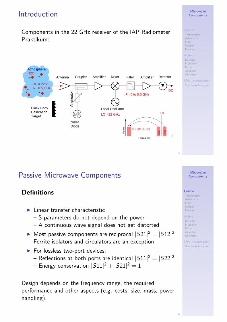
Introduction
Components in the 22 GHz receiver of the IAP RadiometerPraktikum:
Target
Black BodyCalibration
Atte
nuat
or
NoiseDiode
Mixer Filter AmplifierAmplifierCouplerAntenna Detector
+/− 0.5 GHzRF = 22.2
H2OAtmosphere
DCIF =0 to 0.5 GHz
Local Oscillator
LO =22 GHz
Frequency
Pow
er
LO
IF = |RF +/− LO|
LSB
US
B
MicrowaveComponents
Passive
Termination
Attenuator
Filter
Coupler
Ferrites
Active
Detector
Multiplier
Mixer
Amplifier
Oscillator
MW Instruments
Spectrum Analyzer
6
Passive Microwave Components
Definitions
I Linear transfer characteristic– S-parameters do not depend on the power– A continuous wave signal does not get distorted
I Most passive components are reciprocal |S21|2 = |S12|2Ferrite isolators and circulators are an exception
I For lossless two-port devices:– Reflections at both ports are identical |S11|2 = |S22|2– Energy conservation |S11|2 + |S21|2 = 1
Design depends on the frequency range, the requiredperformance and other aspects (e.g. costs, size, mass, powerhandling).

MicrowaveComponents
Passive
Termination
Attenuator
Filter
Coupler
Ferrites
Active
Detector
Multiplier
Mixer
Amplifier
Oscillator
MW Instruments
Spectrum Analyzer
7
Lumped Element Devices
I Discrete network of individual components, e.g. coils,capacitors, resistors.
I Dimensions < λ, phase differences from the assemblycan be neglected.
I Usable up to ∼3GHz (and above), but parasitic effectsand radiation losses increase with frequency.
Example for a lumped element 100MHz bandpass filter of aradio amateur receiver.
MicrowaveComponents
Passive
Termination
Attenuator
Filter
Coupler
Ferrites
Active
Detector
Multiplier
Mixer
Amplifier
Oscillator
MW Instruments
Spectrum Analyzer
8
Distributed Devices
I All components are connected by transmission lineswith dimensions in the order of λ.
I The connections are an integral part of the circuit, e.g.for tuning or impedance matching.
I Usable up to ∼100 GHz (and above).
I Dielectric and ohmic losses increase with frequency, andmanufacturing becomes very demanding.
Example of an integrated 24 GHz receiver module.

MicrowaveComponents
Passive
Termination
Attenuator
Filter
Coupler
Ferrites
Active
Detector
Multiplier
Mixer
Amplifier
Oscillator
MW Instruments
Spectrum Analyzer
9
Quasi-Optics
I At Millimeter and submillimeter wavelengths free spacepropagation provides lowest losses.
I Quasi-optical components with dimensions > λ are usedto guide, split or combine the beams.
Local Oscillatorto Antenna
Image BBHto Cold Sky
Signal BBH
300
mm
FSP Sideband Filterto Cryostat
Quasi-optical module characterized at IAP for the 660 GHzreceiver SMILES, a Japanese remote sensing instrument forthe International Space Station.
MicrowaveComponents
Passive
Termination
Attenuator
Filter
Coupler
Ferrites
Active
Detector
Multiplier
Mixer
Amplifier
Oscillator
MW Instruments
Spectrum Analyzer
10
Termination
I Terminates a transmission line (ideally S11= −∞ dB ).
I Tapered absorbing dielectrics in waveguides (a),resistive films in planar or coaxial devices (b).
I Standard coaxial 0-18 GHz terminations specified withreturn loss < -26dB (VSWR<1.1), expensive matchedtermination for VNA calibration have ≥ -36 dB.
I Free space terminations for anechoic chambers orradiometric calibration targets. Often made of lossyfoams with a pyramidal surface to improve thematching.

MicrowaveComponents
Passive
Termination
Attenuator
Filter
Coupler
Ferrites
Active
Detector
Multiplier
Mixer
Amplifier
Oscillator
MW Instruments
Spectrum Analyzer
11
Attenuator
I Lossy two-port device to reduce the signal level by -xxdB
I Ideally well matched and frequency independent.
I Resistive networks in coaxial (a) and planar devices,absorbing vane in waveguides.
I Often used to reduce standing waves caused bycomponents with a bad matching.
MicrowaveComponents
Passive
Termination
Attenuator
Filter
Coupler
Ferrites
Active
Detector
Multiplier
Mixer
Amplifier
Oscillator
MW Instruments
Spectrum Analyzer
12
Filter
I Used to reject certain frequency bands
I Realized as low-, high or bandpass filter (and alsoband-reject)
1.32 1.34 1.36 1.38 1.4 1.42 1.44 1.46 1.48 1.5−80
−70
−60
−50
−40
−30
−20
−10
0
10
FWHM
Frequency GHz
Am
plitu
de [d
B]
Bandpass Filter for a L−Band Radiometer
S11S12S21S22
Insertion Loss −0.39 dB
Out−of−bandRejection
CenterFrequency
Measurement example of a cavity filter with four sections.FWHM (full width at half maximum)

MicrowaveComponents
Passive
Termination
Attenuator
Filter
Coupler
Ferrites
Active
Detector
Multiplier
Mixer
Amplifier
Oscillator
MW Instruments
Spectrum Analyzer
13
Filter Types and Specifications
Selection depends on frequency and relative bandwidth.
Online tool of the manufacturer K&Lhttp://www.klfilterwizard.com
MicrowaveComponents
Passive
Termination
Attenuator
Filter
Coupler
Ferrites
Active
Detector
Multiplier
Mixer
Amplifier
Oscillator
MW Instruments
Spectrum Analyzer
14
Cavity Filter Example
7.8 GHz high pass filter made out a series of iris coupledwaveguide resonators. Mesh of the finite element model andsimulation results.
Simulated E-fields in the rejection and transmission band.

MicrowaveComponents
Passive
Termination
Attenuator
Filter
Coupler
Ferrites
Active
Detector
Multiplier
Mixer
Amplifier
Oscillator
MW Instruments
Spectrum Analyzer
15
Software for Cavity Filter Design at IAP
I Finite Elements: COMSOL Multphysics, Agilent EMDS
I Mode Matching: S&P (written by P. Fuholz)MICIAN ”Microwave Wizard”
MicrowaveComponents
Passive
Termination
Attenuator
Filter
Coupler
Ferrites
Active
Detector
Multiplier
Mixer
Amplifier
Oscillator
MW Instruments
Spectrum Analyzer
16
Planar Filter
Steps to get from a lumped element lowpass filter (a) to anequivalent microstrip design (d).
Inductors and capacitors are replaced by microstrip ”stubs”.Easy to integrate in a circuit, but degraded out of bandperformance.
MicrowaveComponents
Passive
Termination
Attenuator
Filter
Coupler
Ferrites
Active
Detector
Multiplier
Mixer
Amplifier
Oscillator
MW Instruments
Spectrum Analyzer
17
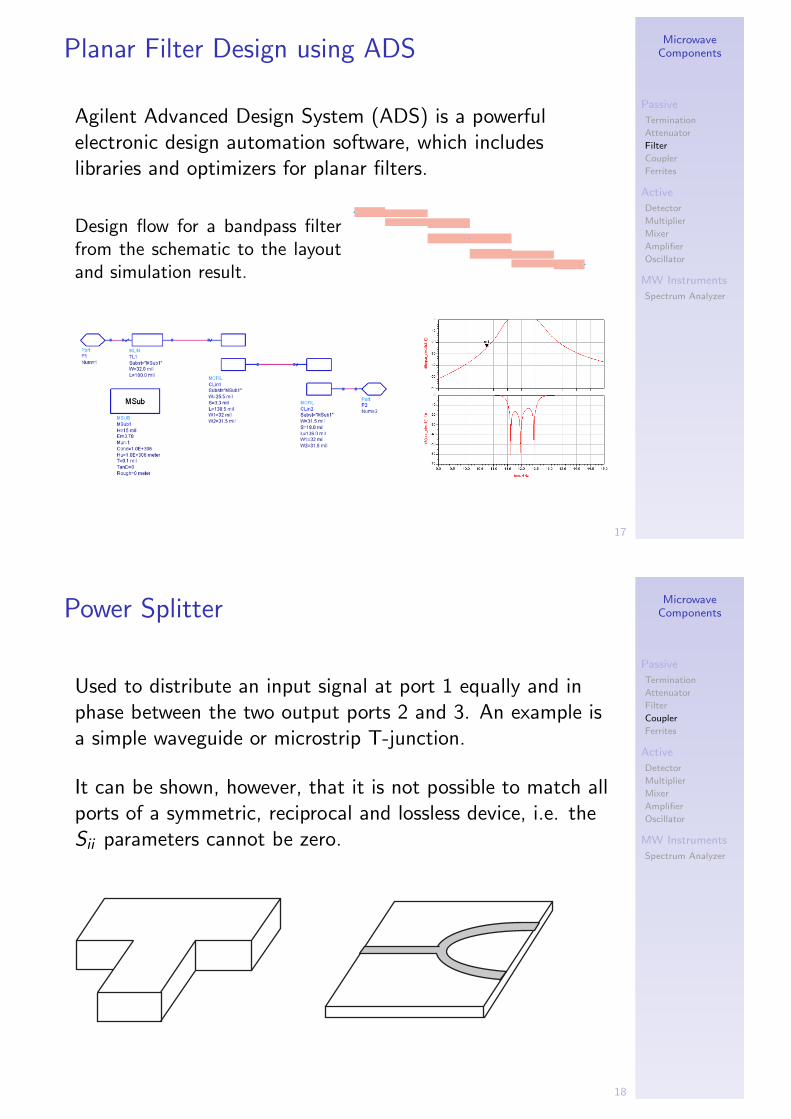
Planar Filter Design using ADS
Agilent Advanced Design System (ADS) is a powerfulelectronic design automation software, which includeslibraries and optimizers for planar filters.
Design flow for a bandpass filterfrom the schematic to the layoutand simulation result.
MicrowaveComponents
Passive
Termination
Attenuator
Filter
Coupler
Ferrites
Active
Detector
Multiplier
Mixer
Amplifier
Oscillator
MW Instruments
Spectrum Analyzer
18
Power Splitter
Used to distribute an input signal at port 1 equally and inphase between the two output ports 2 and 3. An example isa simple waveguide or microstrip T-junction.
It can be shown, however, that it is not possible to match allports of a symmetric, reciprocal and lossless device, i.e. theSii parameters cannot be zero.

MicrowaveComponents
Passive
Termination
Attenuator
Filter
Coupler
Ferrites
Active
Detector
Multiplier
Mixer
Amplifier
Oscillator
MW Instruments
Spectrum Analyzer
19
Resistive Power Splitter
I A simple resistive power splitter is matched at all portsand has a wide bandwidth, but it has additional -3dBloss and ports 2 and 3 are not isolated.
I The Wilkinson power divider has a limited bandwidth,but it is lossless for S21 and S31, and ports 2 and 3 are
isolated. For an ideal device [S ] = −j√2
0 1 11 0 01 0 0
MicrowaveComponents
Passive
Termination
Attenuator
Filter
Coupler
Ferrites
Active
Detector
Multiplier
Mixer
Amplifier
Oscillator
MW Instruments
Spectrum Analyzer
20
Directional Coupler
I 4-port device, input port 1 is isolated from port 4.
I Splits the power coming from port 1 equally or with adifferent coupling ratio between ports 2 and 3.
I Most important characteristics:Directivity, bandwidth, phase and amplitude balance
I Very usefull to measure the return loss of a device.
Reflectometer setup with a directional coupler to measurethe return loss ρL of a device. which corresponds to thepower ration P4/P3.

Directional Coupler
10-dB 1.7-2.2 dB directional coupler. From left to right: input, coupled, isoated, and transmitted port
Coupling = - 10 log(P3/P1)
Insertion loss = - 10 log (P2/P1)
Coupling loss = -10 log (1-P3/P1)
Isolation = - 10 log (P4/P1)
Directivity = - 10 log (P4/P3)
MicrowaveComponents
Passive
Termination
Attenuator
Filter
Coupler
Ferrites
Active
Detector
Multiplier
Mixer
Amplifier
Oscillator
MW Instruments
Spectrum Analyzer
21
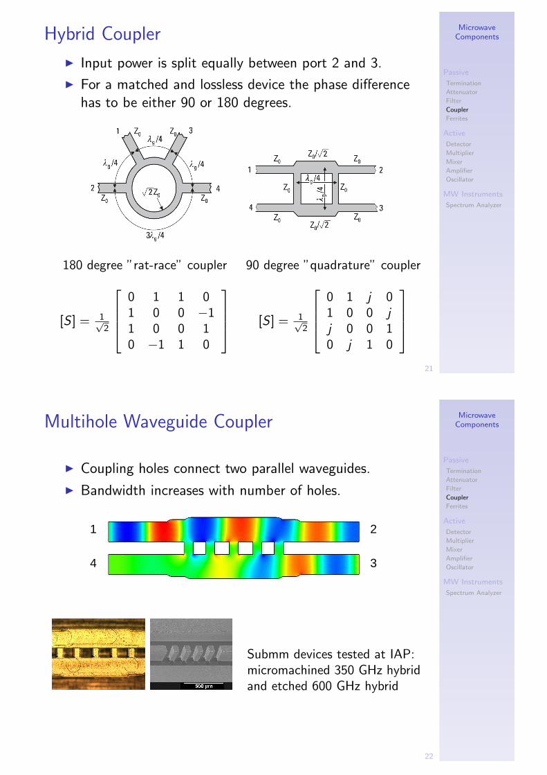
Hybrid Coupler
I Input power is split equally between port 2 and 3.
I For a matched and lossless device the phase differencehas to be either 90 or 180 degrees.
180 degree ”rat-race” coupler 90 degree ”quadrature” coupler
[S ] = 1√2
0 1 1 01 0 0 −11 0 0 10 −1 1 0
[S ] = 1√2
0 1 j 01 0 0 jj 0 0 10 j 1 0
MicrowaveComponents
Passive
Termination
Attenuator
Filter
Coupler
Ferrites
Active
Detector
Multiplier
Mixer
Amplifier
Oscillator
MW Instruments
Spectrum Analyzer
22
Multihole Waveguide Coupler
I Coupling holes connect two parallel waveguides.
I Bandwidth increases with number of holes.
3 4
1 2
Submm devices tested at IAP:micromachined 350 GHz hybridand etched 600 GHz hybrid

MicrowaveComponents
Passive
Termination
Attenuator
Filter
Coupler
Ferrites
Active
Detector
Multiplier
Mixer
Amplifier
Oscillator
MW Instruments
Spectrum Analyzer
23
Examples of Microstrip Couplers
return loss
-30
-20
-10
0
10
20
30
40
0 20 40 60 80 100 120
frequency [GHz]
[dB
]
directivity
insertion loss
coupling
Simple proximity coupler with wide bandwidth
Optimized step-design with λ/4 matching sections.
MicrowaveComponents
Passive
Termination
Attenuator
Filter
Coupler
Ferrites
Active
Detector
Multiplier
Mixer
Amplifier
Oscillator
MW Instruments
Spectrum Analyzer
24
Ferrites
I Ferromagnetic ceramic (Fe2O3+impurities) withhigh resistivity, µr > 1000, εr < 10.
I Can be magnetized permanently by an externalmagnetic field.
I Electromagnetic waves interact with the magneticdipoles.
I Propagation parallel to−→H results
in different effective permeabilityµ+
r and µ−r for left- and right-handed circular polarization, andthus in different propagation con-stants (Faraday rotation):
µ± = µ0
(1 + γµ0MS
ω0±ω
)Larmor frequency ω0 = γB0

MicrowaveComponents
Passive
Termination
Attenuator
Filter
Coupler
Ferrites
Active
Detector
Multiplier
Mixer
Amplifier
Oscillator
MW Instruments
Spectrum Analyzer
25
Faraday Isolator
I Non-reciprocal two-port device to reduce standingwaves (ideally S21 = 1 and S12 = 0)
I Resistive vanes at both ports of a circular waveguide areoriented at an angle of 45 to each other and absorbenergy when they are parallel to the E field.
I Ferrite rod in the center rotates the polarization by±45, depending on the propagation direction.
MicrowaveComponents
Passive
Termination
Attenuator
Filter
Coupler
Ferrites
Active
Detector
Multiplier
Mixer
Amplifier
Oscillator
MW Instruments
Spectrum Analyzer
26
Circulator
I Non-reciprocal three-port device with a ferrite post atthe junction.
I Allows to use the same antenna for transmission andreception (radar, communications).
I Absorbers for low frequencies.
Circulator example simulated with COMSOL Multiphysics

MicrowaveComponents
Passive
Termination
Attenuator
Filter
Coupler
Ferrites
Active
Detector
Multiplier
Mixer
Amplifier
Oscillator
MW Instruments
Spectrum Analyzer
27
Isolator Example
I Measured performance of a high quality 1.4 GHzisolator, which will be used in an L-band radiometer forSMOS validation
I Good performance only over a very narrow bandwidth
I Isolation, loss and matching degrade outside of thespecified frequency band
1 1.2 1.4 1.6 1.8 2 2.2 2.4 2.6 2.8 3−60
−50
−40
−30
−20
−10
0 −0.07 dB
Frequency GHz
Am
plitu
de [d
B]
Measurement of a 1.4 GHz narrow−band isolator
S11S12S21S22
MicrowaveComponents
Passive
Termination
Attenuator
Filter
Coupler
Ferrites
Active
Detector
Multiplier
Mixer
Amplifier
Oscillator
MW Instruments
Spectrum Analyzer
28
Other Ferrite Devices
I Waveguide switch by reversing the magnetic fieldof a circulator.
I Variable phase shifters for electronic beam steering
I Attenuator for low frequencies
I Tunable filters and oscillators

MicrowaveComponents
Passive
Termination
Attenuator
Filter
Coupler
Ferrites
Active
Detector
Multiplier
Mixer
Amplifier
Oscillator
MW Instruments
Spectrum Analyzer
29
Common Symbols for Passive Devices
MicrowaveComponents
Passive
Termination
Attenuator
Filter
Coupler
Ferrites
Active
Detector
Multiplier
Mixer
Amplifier
Oscillator
MW Instruments
Spectrum Analyzer
30
Active Components
I Nonlinear transfer characteristic leads to signaldistortions and frequency conversion (b), which is notthe case on a linear curve (a).
I Nonlinear devices can still have an almost linearbehavior for small scale signals (c)

MicrowaveComponents
Passive
Termination
Attenuator
Filter
Coupler
Ferrites
Active
Detector
Multiplier
Mixer
Amplifier
Oscillator
MW Instruments
Spectrum Analyzer
31
Power Measurements
I Different ways to measure electric power,depending on the frequency range:
DC −→ voltmeter + amperemeterAC to ∼ GHz −→ oscilloscopeAC to ∼ 0.1 THz −→ diode detectorAC to > THz −→ bolometer
I Other selection criteria:I Power range (nW or kW?)I Accuracy (absolute or relative?)I Linearity (required dynamic range?)I Time constant (continuous wave or modulated?)
MicrowaveComponents
Passive
Termination
Attenuator
Filter
Coupler
Ferrites
Active
Detector
Multiplier
Mixer
Amplifier
Oscillator
MW Instruments
Spectrum Analyzer
32
Bolometric Detection
I Microwave energy is absorbed and heats the device, thetemperature change ∆T = R · P is measured with athermometer.
Thermometer
Thermal conductance RRadiation
PAbsorber T(P)
Heat sinkT = const
0
I Advantages: good power handling, no fundamentalfrequency limit, possibility for absolute calibration.
I Disadvantages (which can be overcome):relative slow, not very sensitive, thermal drift.

MicrowaveComponents
Passive
Termination
Attenuator
Filter
Coupler
Ferrites
Active
Detector
Multiplier
Mixer
Amplifier
Oscillator
MW Instruments
Spectrum Analyzer
33
Cryogenic BolometersMost sensitive detectors used in radio astronomy:
I Cooled below 0.5 K
I ”Spiderweb” geometry to minimize mass, heat capacityand thermal conductivity
I Used in many cosmic background experiments
Complete bolometer array and close-up
views of the spiderweb bolometers.
MicrowaveComponents
Passive
Termination
Attenuator
Filter
Coupler
Ferrites
Active
Detector
Multiplier
Mixer
Amplifier
Oscillator
MW Instruments
Spectrum Analyzer
34
Diode Detector
I Junction betwee semiconductors with different doping(p-n diode) or metal-semiconductor (Schottky diode).
I Non-linear I/V curve rectifies the RF signal.For small signals it can be approximated by a quadraticcurve, and the DC output signal is linear with the inputpower.
n
p_ _ _+ + +
For
war
d di
rect
ion
brea
kdow
n vo
ltage reverse current I
0
V
I reverse bias forward bias
I = I0 [exp(V/V
0)−1]
⟨ I(t)⟩ > 0
V(t)

MicrowaveComponents
Passive
Termination
Attenuator
Filter
Coupler
Ferrites
Active
Detector
Multiplier
Mixer
Amplifier
Oscillator
MW Instruments
Spectrum Analyzer
35
Characteristics of Diode Detectors
I Advantages:
I Very fast (rise times < ns), relative sensitive
I Disadvantages:
I Easily destroyed by ESD (electrostatic discharge)I Moderate linearity and temperature stabilityI Upper frequency cut-off given by the parasitic capacity
of the junction
Response of a typical diode de-tector. Only in the square-lawregion the output signal is pro-portional to the input power.
MicrowaveComponents
Passive
Termination
Attenuator
Filter
Coupler
Ferrites
Active
Detector
Multiplier
Mixer
Amplifier
Oscillator
MW Instruments
Spectrum Analyzer
36
Diode Layout
To use diodes at THz frequen-cies the junction area needsto be as small as possible,which is achieved by point-likewhisker contacts or very smallplanar devices.
F i g . 1 . S c a n n i n g e l e c t r o n m i c r o g r a p h o f a p l a n a r S c h o t t k yb a r r i e r d i o d e . C h i p d i m e n s i o n s a p p r o x i m a t e l y 1 8 0 x 8 0 x 4 0 m .

MicrowaveComponents
Passive
Termination
Attenuator
Filter
Coupler
Ferrites
Active
Detector
Multiplier
Mixer
Amplifier
Oscillator
MW Instruments
Spectrum Analyzer
37
Frequency Multiplication
A nonlinear device generates harmonics of an input signalwith the fundamental frequency f0.
Time
V(t
)
Time
|V(t
)|
−40
−30
−20
−10
0
Frequency
Am
plitu
de [d
B] f
0
−40
−30
−20
−10
0
Frequency
Am
plitu
de [d
B] 0
2f0
4f0
6f0 8f
0
MicrowaveComponents
Passive
Termination
Attenuator
Filter
Coupler
Ferrites
Active
Detector
Multiplier
Mixer
Amplifier
Oscillator
MW Instruments
Spectrum Analyzer
38
Examples of Frequency Multipliers

MicrowaveComponents
Passive
Termination
Attenuator
Filter
Coupler
Ferrites
Active
Detector
Multiplier
Mixer
Amplifier
Oscillator
MW Instruments
Spectrum Analyzer
39
Heterodyne Principle
I Superposition of a strong local oscillator (LO) signalwith a weaker radio frequency (RF ) signal on nonlineardevice generates an intermediate frequencyIF = |LO ± RF |
I Normal double sideband mixers (DSB) convert bothsidebands, single sideband conversion (SSB) requires aRF filter or a special mixer.
LO
MixerRF IF
US
B
IF
LSB
2 LO
RF + LOLO
up−conversiondown−conversion
Pow
er
Frequency
LO−RF
RF−LO
MicrowaveComponents
Passive
Termination
Attenuator
Filter
Coupler
Ferrites
Active
Detector
Multiplier
Mixer
Amplifier
Oscillator
MW Instruments
Spectrum Analyzer
40
Mixers Designs
I Single ended mixer (a): Common for mm wavelengths.No isolation between RF and LO.
I Balanced mixer (b): Two mixing elements, 3dB hybridcombines LO and RF. Good LO to RF isolation, LOnoise and spurious harmonics are rejected.
I Double balanced mixer (c): Also IF port is isolated,dynamic range is improved.

MicrowaveComponents
Passive
Termination
Attenuator
Filter
Coupler
Ferrites
Active
Detector
Multiplier
Mixer
Amplifier
Oscillator
MW Instruments
Spectrum Analyzer
41
Subharmonic Mixer
I Antiparallel diode pair down-converts with the secondLO harmonic IF = |RF − 2LO|
I Advantages:Lower LO frequency and good LO/RF isolation.
I Disadvantages:Higher conversion loss and LO power requirement.
RF
LO
IF
RF filter
diode pair
IF Filter
MicrowaveComponents
Passive
Termination
Attenuator
Filter
Coupler
Ferrites
Active
Detector
Multiplier
Mixer
Amplifier
Oscillator
MW Instruments
Spectrum Analyzer
42
SIS Mixer
Superconductor-Isolator-Superconductor tunnel junction:
I Two Niobium layers at 4K (ρΩ = 0),separated a 2 nm thick Al2O3 barrier
I Cooper-pairs (2e−) tunnel through the barrier,resulting in a sharp bend in the I/V curve
0 2 4 60
100
200
300
400
bia
s c
urr
ent I 0
[µA
]
bias voltage U0 [mV]
V0
superconductor
insulator
superconductor
I0
a) b)
V0
MicrowaveComponents
Passive
Termination
Attenuator
Filter
Coupler
Ferrites
Active
Detector
Multiplier
Mixer
Amplifier
Oscillator
MW Instruments
Spectrum Analyzer
43
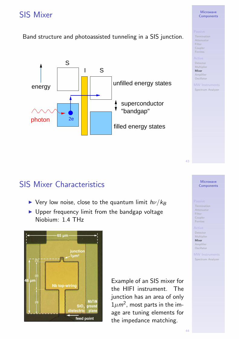
SIS Mixer
Band structure and photoassisted tunneling in a SIS junction.
superconductor"bandgap"
SS
I
energy
2ephoton
unfilled energy states
filled energy states
MicrowaveComponents
Passive
Termination
Attenuator
Filter
Coupler
Ferrites
Active
Detector
Multiplier
Mixer
Amplifier
Oscillator
MW Instruments
Spectrum Analyzer
44
SIS Mixer Characteristics
I Very low noise, close to the quantum limit hν/kB
I Upper frequency limit from the bandgap voltageNiobium: 1.4 THz
65 µm
NbTiN
ground
plane
SiO2
dielectric
Nb top-wiring
(1)
(2)
(3)
48 µm
junction
1µm2
feed point
Example of an SIS mixer forthe HIFI instrument. Thejunction has an area of only1µm2, most parts in the im-age are tuning elements forthe impedance matching.

MicrowaveComponents
Passive
Termination
Attenuator
Filter
Coupler
Ferrites
Active
Detector
Multiplier
Mixer
Amplifier
Oscillator
MW Instruments
Spectrum Analyzer
45
HEB MixerI Hot Electron Bolometers (HEB) are extremely fast
bolometers, which can be used as mixing element.I Superconducting microbridge (d <10 nm) close to the
transition temperature.I No fundamental RF frequency limit (>2THz)I Limited IF bandwidth (∼ 5 GHz) given by cooling rate
of the electrons.
MicrowaveComponents
Passive
Termination
Attenuator
Filter
Coupler
Ferrites
Active
Detector
Multiplier
Mixer
Amplifier
Oscillator
MW Instruments
Spectrum Analyzer
46
Amplifier
I Increase signal amplitude
I Made with bipolar or FETtransistors
I Tradeoff between low noiseand high power
bias out
in
CB
E
n AlGaAs
undoped GaAs
n+
HEMT−FET transistorbipolar transistor
source gate drainbaseemitter
collectorGaAs
n p
quantum−well with 2DEG
Schematic of a bipolar npn transistor and a High ElectronMobility (HEMT) field effect transistor, which works with a2D electron gas in a quantum well.
MicrowaveComponents
Passive
Termination
Attenuator
Filter
Coupler
Ferrites
Active
Detector
Multiplier
Mixer
Amplifier
Oscillator
MW Instruments
Spectrum Analyzer
47
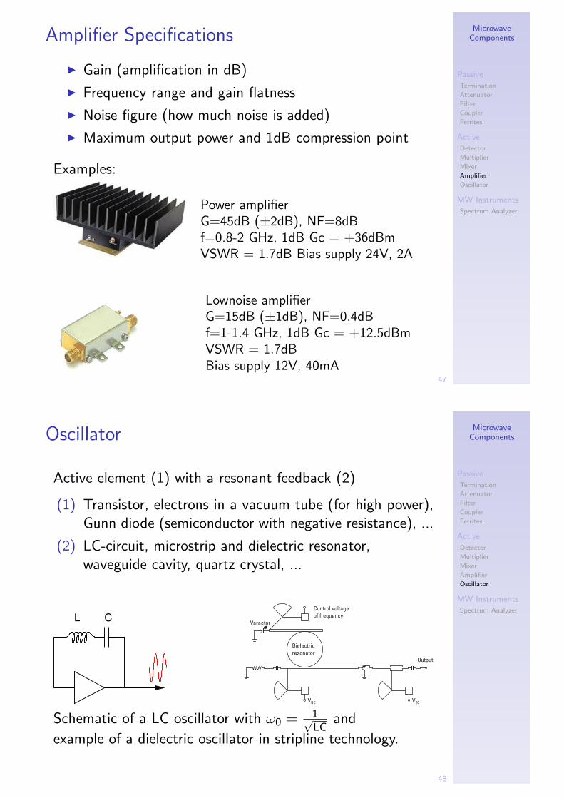
Amplifier Specifications
I Gain (amplification in dB)
I Frequency range and gain flatness
I Noise figure (how much noise is added)
I Maximum output power and 1dB compression point
Examples:
Power amplifierG=45dB (±2dB), NF=8dBf=0.8-2 GHz, 1dB Gc = +36dBmVSWR = 1.7dB Bias supply 24V, 2A
Lownoise amplifierG=15dB (±1dB), NF=0.4dBf=1-1.4 GHz, 1dB Gc = +12.5dBmVSWR = 1.7dBBias supply 12V, 40mA
MicrowaveComponents
Passive
Termination
Attenuator
Filter
Coupler
Ferrites
Active
Detector
Multiplier
Mixer
Amplifier
Oscillator
MW Instruments
Spectrum Analyzer
48
Oscillator
Active element (1) with a resonant feedback (2)
(1) Transistor, electrons in a vacuum tube (for high power),Gunn diode (semiconductor with negative resistance), ...
(2) LC-circuit, microstrip and dielectric resonator,waveguide cavity, quartz crystal, ...
L C
Schematic of a LC oscillator with ω0 = 1√LC
and
example of a dielectric oscillator in stripline technology.

MicrowaveComponents
Passive
Termination
Attenuator
Filter
Coupler
Ferrites
Active
Detector
Multiplier
Mixer
Amplifier
Oscillator
MW Instruments
Spectrum Analyzer
49
Magnetron
I Microwave generator for high output power (>1MW)with good efficiency (>80%)
I A high electric field accelerates electrons in a circularcavity, a magnetic field forces them on a spiral pathwhich excites microwave resonances.
I Standard for microwave ovens and radar systems
MicrowaveComponents
Passive
Termination
Attenuator
Filter
Coupler
Ferrites
Active
Detector
Multiplier
Mixer
Amplifier
Oscillator
MW Instruments
Spectrum Analyzer
50
Oscillator Specifications
I Frequency accuracy and stability
I Phase noise (specified in dB below carrier [dBc])
I Harmonic and spurious signals
I Phase noise and short term accuracy depends on thequality of the resonator (Q-factor).
Phase Noise
Residual FM
Spurious
non-harmonic spur
~65dBc
harmonic spur
~30dBc
CW output
Residual FM is the integrated
phase noise over 300 Hz - 3
kHz BW phase
noise
0.5 f0 f0 2f0
sub-harmonics

MicrowaveComponents
Passive
Termination
Attenuator
Filter
Coupler
Ferrites
Active
Detector
Multiplier
Mixer
Amplifier
Oscillator
MW Instruments
Spectrum Analyzer
51
Oscillator Types
I Atomic clocks (Cs or Rb) for absolute time standardswith ∆f /f < 10−15 (e.g. at METAS, UniNE, NIST)
I Quartz oscillators as reference signals up to 100 MHzreach ∆f /f = 10−6 to 10−9, depending on temperaturecompensation or temperature stabilization.
I All higher frequencies are usually synchronized to aquartz crystal with a phase-locked loop (PLL).
free running phase lockedExample of a 6 GHz cavity oscillator
MicrowaveComponents
Passive
Termination
Attenuator
Filter
Coupler
Ferrites
Active
Detector
Multiplier
Mixer
Amplifier
Oscillator
MW Instruments
Spectrum Analyzer
52
Modulation Analog
I Amplitude modulation (AM): VAM = A(t) sin(f0 · t)
Volta
ge
Time
Carrier
Modulation
I Frequency modulation (FM): VFM = A0 sin(f (t) · t)Phase Modulation (PM): VPM = A0 sin(f0 · t + φ(t))
Volta
ge
Time

MicrowaveComponents
Passive
Termination
Attenuator
Filter
Coupler
Ferrites
Active
Detector
Multiplier
Mixer
Amplifier
Oscillator
MW Instruments
Spectrum Analyzer
53
Modulation Digital
Amplitude
Frequency
Phase
Quadrature phase-shift keying (QPSK):Digital ModulationPolar Display: Magnitude & Phase Represented Together
Magnitude is an absolute value
Phase is relative to a reference signal
Phase
Mag
0 deg
QPSK IQ Diagram
I
Q
0001
1011
MicrowaveComponents
Passive
Termination
Attenuator
Filter
Coupler
Ferrites
Active
Detector
Multiplier
Mixer
Amplifier
Oscillator
MW Instruments
Spectrum Analyzer
54
Spectrum Analysis:From Time- to Frequency Domain
: ; 4
8 &4
8
To increase the frequency resolution a longer time series hasto be analyzed.

MicrowaveComponents
Passive
Termination
Attenuator
Filter
Coupler
Ferrites
Active
Detector
Multiplier
Mixer
Amplifier
Oscillator
MW Instruments
Spectrum Analyzer
55
Spectrum Analyzer
I Realtime analyzer measures all channels simultaneously⇒ best signal-to-noise ratio for a given integration time
I Swept spectrum analyzer moves a filter over thespectrum ⇒ flexible standard instrument for mostmeasurement tasks
)=
&1 1"
)=
"#
MicrowaveComponents
Passive
Termination
Attenuator
Filter
Coupler
Ferrites
Active
Detector
Multiplier
Mixer
Amplifier
Oscillator
MW Instruments
Spectrum Analyzer
56
Realtime Spectrum Analyzer
I Filterbank spectrometerSize, cost and power consumption increase linear withnumber of channels.
I Acousto Optical Spectrometer (AOS)Bandwidth up to 1 GHz, typically 1-2k channels.
I Digital autocorrelation and FFT spectrometer1 GHz bandwidth with 16k channels in a small unit.Cost effective and rapidly evolving because of the hugemarked for digital technology.

MicrowaveComponents
Passive
Termination
Attenuator
Filter
Coupler
Ferrites
Active
Detector
Multiplier
Mixer
Amplifier
Oscillator
MW Instruments
Spectrum Analyzer
57
Acousto Optical Spectrometer (AOS)
I IF signal is converted to an acoustic wave in a crystal(Bragg-cell), which modulates its refractive index.
I A collimated laser beam is diffracted by the resultingphase grating.
I A linear CCD array detects the image, which representsthe IF spectrum.
MicrowaveComponents
Passive
Termination
Attenuator
Filter
Coupler
Ferrites
Active
Detector
Multiplier
Mixer
Amplifier
Oscillator
MW Instruments
Spectrum Analyzer
58
Digital FFT Spectrometer
I IF signal is sampled with a fast Analog/DigitalConverter (ADC) with sampling rate fs .
I Time record of N samples is Fourier transformed inrealtime in a fast FPGA processor.
I The averaged power spectra cover a bandwidth of fs/2with a frequency resolution of fs/N.
....
.. .
..
....
.....
.. .ADC FFT
N = Number of sample points (*powers of 2)
Sampling
fs = Sampling frequency (sampling rate) = (N/2) + 1
Spectrum display
n = Number of lines (or bins)
∆ t
T
= N x t = 1/ f
T = Time record length f = Frequency step
= 1/T = fs/Nt = 1/fs = Sample time
∆ f
00 N
Window
Timerecord
Time records1 2 ...n
Time record
Frequency range
Lines (N/2)
0 (fs/2)
Samplesfs
N/fs0
.

MicrowaveComponents
Passive
Termination
Attenuator
Filter
Coupler
Ferrites
Active
Detector
Multiplier
Mixer
Amplifier
Oscillator
MW Instruments
Spectrum Analyzer
59
Swept Spectrum Analyzer
I LO of a heterodyne receiver is swept over the frequencyrange of interest
I Resolution bandwidth (RBW) can be adjusted bychanging the IF filter
2'
+)
&
=
)
&
5
&
"
&
=
MicrowaveComponents
Passive
Termination
Attenuator
Filter
Coupler
Ferrites
Active
Detector
Multiplier
Mixer
Amplifier
Oscillator
MW Instruments
Spectrum Analyzer
60
Effect of RBW and VBW
RBW determines the frequency resolution. Smaller RBWreduces the noise floor, but increases sweep time:
*"
0"
"
0'
536
FF$/!.%
F$/!.%
$/!.%
F.
F.
Video Bandwidth (VBW) determines smoothing of thespectrum:

MicrowaveComponents
Passive
Termination
Attenuator
Filter
Coupler
Ferrites
Active
Detector
Multiplier
Mixer
Amplifier
Oscillator
MW Instruments
Spectrum Analyzer
61
Spectrum Analyzer: Filters and Detectors
Digital filters and FFT processing improve speed andchannel selectivity at narrow bandwidths.
);*;
0'
'*0''
*:"
**
''
" @''
8A"
*0=0 :'0: 23
>:='0: 23
'(,$/!<'.%FF/!
Different ways to analyze the detector output, depending onthe measurement task (e.g. RMS for noise measurements):
("9 "
"9 "
'9"
G G
+ 9(: ;#
":8' ;