Embed Size (px)
Citation preview

7/28/2019 pcd03l8
http://slidepdf.com/reader/full/pcd03l8 1/13
128 December 2010 (Version 1.03)
Small World Communications PCD03L8 LTE Turbo Decoder
28 December 2010 (Version 1.03) Product Specification
PCD03L8 FeaturesTurbo Decoder
8 state 3GPPTM LTE compatible
Rate 1/3
40 to 6144 bit interleaver
Up to 185 MHz internal clock
Up to 130 Mbit/s with 5 decoder iterations
6–bit signed magnitude input data
8 parallel MAP decoders
Optional log–MAP or max–log–MAP constitu-
ent decoder algorithms
Up to 32 iterations in 1/2 iteration steps.
Optional power efficient early stopping
Optional extrinsic information scaling and limit-
ing
Estimated channel error output
Free simulation software
Available as EDIF core and VHDL simulation
core for Xilinx Virtex–II, Spartan–3, Virtex–4,
Virtex–5, Virtex–6 and Spartan–6 FPGAs under
SignOnce IP License. Actel, Altera and Lattice
FPGA cores available on request. Available as VHDL core for ASICs
Low cost university license also available
IntroductionThe PCD03L8 is a fully compatible 3GPPTM
LTE [1] error control decoder. 3GPPTM LTE uses
a simple quadratic permutation interleaver.
For LTE, there are 188 interleaver sizes rang-
ing from 40 to 6144 bits. Two parameters f 1 and
f 2 are used by the interleaver. All interleaver sizes
from 40 to 504 bits that are a multiple of 8, 512 to
1008 bits that are a multiple of 16, 1024 to 2016
bits that are multiple of 32, and 2048 to 6144 bits
that are a multiple of 64 are specified.
For LTE only a code rate of 1/3 is specified.
Each tail of the two constituent encoders are ter-
minated using all the data and parity bits (for a
total of 12 bits for rate 1/3).
Eight MAP03L MAP decoder cores are used
with the PCD03L8 core to iteratively decode the
LTE turbo code. The Log–MAP algorithm for
maximum performance or the max–log–MAP al-
gorithm for minimum complexity and highest
CLK
Figure 1: PCD03L8 schematic symbol.
K[12:0]
MODE[1:0]
XDR
DEC_END
XDA[9:0]
RR
START
RST
SLD
C[4:0]
SCLZ[5:0]
LIMZ[6:0]
ZTH[6:0]M[1:0]
NI[5:0]
NA[5:0]
XD[7:0]
RA[9:0]
R1I[47:0]
R2I[47:0]
ERR[7:0]
PR
TA[2:0]
RTI[11:0]
PA[9:0]
FS
F1I[8:1]
F2I[9:1]
TR
R0I[47:0]
XDE
MAG[7:0]
speed can be selected. The extrinsic information
can be optionally scaled and limited with each half
iteration, improving performance with max–log–
MAP decoding.
The reverse sliding block algorithm is used
with sliding block lengths of 5 to 127 for K from 40
to 504 and sliding block lengths from 32 to 127 for
K from 512 to 6144. The actual sliding block length
L depends on the data length K and input SLD.
Six–bit quantisation is used for maximum per-
formance.
The turbo decoder can achieve up to 130
Mbit/s with 5 iterations and log–MAP decoding
using a 185 MHz internal clock (K = 6114). Log–
MAP decoding decreases speed by about 30%.
Optional early stopping allows the decoder to
greatly reduce power consumption with little deg-
radation in performance.
Figure 1 shows the schematic symbol for the
PCD03L8 decoder. The EDIF core can be used
with Xilinx Integrated Software Environment (ISE)
7/28/2019 pcd03l8
http://slidepdf.com/reader/full/pcd03l8 2/13
PCD03L8Small World Communications
228 December 2010 (Version 1.03)
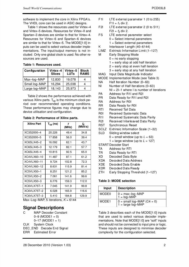
software to implement the core in Xilinx FPGA’s.
The VHDL core can be used in ASIC designs.
Table 1 shows the resources used for Virtex–4
and Virtex–5 devices. Resources for Virtex–II and
Spartan–3 devices are similar to that for Virtex–4.
Resources for Virtex–6 and Spartan–6 devices
are similar to that for Virtex–5. The MODE[1:0] in-
puts can be used to select various decoder imple-mentations. The input/output memory is not in-
cluded. Only one global clock is used. No other re-
sources are used.
Table 1: Resources used.
Configuration Virtex–4Slices
Virtex–5LUTs
BlockRAMS
Max–log–MAP 12,830 19,078 4
Small log–MAP 16,294 25,038 4
Large log–MAP 18,143 25,973 4
Table 2 shows the performance achieved with
various Xilinx parts. Tcp is the minimum clock pe-
riod over recommended operating conditions.
These performance figures may change due to
device utilisation and configuration.
Table 2: Performance of Xilinx parts.
Xilinx Part Tcp (ns) f
(MHz)f d
(Mbit/s)
XC3S2000–4 20.226 49.4 34.8
XC3S2000–5 17.858 56.0 39.4
XC6SLX45–2 16.092 62.1 43.7
XC6SLX45–3 12.179 82.1 57.7
XC6SLX45–4 10.815 92.5 65.0
XC4VLX60–10 11.487 87.1 61.2
XC4VLX60–11 9.724 102.8 72.3
XC4VLX60–12 8.631 115.9 81.4
XC5VLX50–1 8.251 121.2 85.2
XC5VLX50–2 7.061 141.6 99.6
XC5VLX50–3 6.276 159.3 112.0
XC6VLX75T–1 7.045 141.9 99.8XC6VLX75T–2 6.028 165.9 116.6
XC6VLX75T–3 5.410 184.8 129.9
Max–Log–MAP, 5 iterations, K = 6144
Signal DescriptionsC MAP Decoder Constant
0–9 (MODE1 = 0)
0–17 (MODE1 = 1)
CLK System Clock
DEC_END Decode End Signal
ERR Estimated Error
F1I LTE external parameter 1 (0 to 255)
F1I = f 1 div 2.
F2I LTE external parameter 2 (0 to 511)
F2I = f 2 div 2.
FS LTE external parameter select
0 = Select internal parameters
1 = Select external parameters
K Interleaver Length (40–6144)LIMZ Extrinsic Information Limit (1–127)
M Early Stopping Mode
0 = no early stopping
1 = early stop at odd half iteration
2 = early stop at even half iteration
3 = early stop at any half iteration
MAG Input Data Magnitude Indicator
MODE Implementation Mode (see Table 3)
NA Half Iteration Number (0–63)
NI Number of Half Iterations (0–63)
NI = 2I–1 where I is number of iterations
PA Address for R1I and R2IPR Data Ready for R1I and R2I
RA Address for R0I
RR Data Ready for R0I
RTI Received Tail Data
R0I Received Systematic Data
R1I Received Systematic Data Parity
R2I Received Interleaved Data Parity
RST Synchronous Reset
SCLZ Extrinsic Information Scale (1–32)
SLD Sliding window select
0 = small window (up to L = 63)
1 = large window (up to L = 127)START Decoder Start
TA Address for RTI
TR Data Ready for RTI
XD Decoded Data Byte
XDA Decoded Data Address
XDE Decoded Data Enable
XDR Decoded Data Ready
ZTH Early Stopping Threshold (1–127)
Table 3: MODE selection
Input Description
MODE0 0 = max–log–MAP1 = log–MAP
MODE1 0 = small log–MAP (C4 = 0)1 = large log–MAP
Table 3 describes each of the MODE[1:0] inputs
that are used to select various decoder imple-
mentations. Note that MODE[1:0] are “soft” inputs
and should not be connected to input pins or logic.
These inputs are designed to minimise decoder
complexity for the configuration selected.
7/28/2019 pcd03l8
http://slidepdf.com/reader/full/pcd03l8 3/13
PCD03L8Small World Communications
328 December 2010 (Version 1.03)
A–A
01
BPSK
P
Q
QPSK
P
Q
Ań 2Ǹ – Ań 2Ǹ
– Ań 2Ǹ
Ań 2ǸA
0010
0111
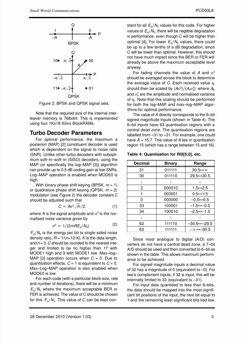
Figure 2: BPSK and QPSK signal sets.
Note that the required size of the internal inter-
leaver memory is 768x64. This is implemented
using four 1Kx18 Xilinx BlockRAMs.
Turbo Decoder ParametersFor optimal performance, the maximum a
posteriori (MAP) [2] constituent decoder is used
which is dependent on the signal to noise ratio
(SNR). Unlike other turbo decoders with subopti-
mum soft–in–soft–in (SISO) decoders, using the
MAP (or specifically the log–MAP [3]) algorithm
can provide up to 0.5 dB coding gain at low SNRs.
Log–MAP operation is enabled when MODE0 is
high.With binary phase shift keying (BPSK, m = 1)
or quadrature phase shift keying (QPSK, m = 2)
modulation (see Figure 2) the decoder constant C
should be adjusted such that
C + A s 2 m Ǹ ń2. (1)
where A is the signal amplitude and s 2 is the nor-
malised noise variance given by
s 2 + 1ń(2mRE b ńN 0).
(2)
E b ńN 0 is the energy per bit to single sided noise
density ratio, R = 1/(n +12/ K ), K is the data length,
and n = 3.C should be rounded to the nearest inte-ger and limited to be no higher than 17 with
MODE1 high and 9 with MODE1 low. Max–log–
MAP [3] operation occurs when C = 0. Due to
quantisation effects, C = 1 is equivalent to C = 0.
Max–Log–MAP operation is also enabled when
MODE0 is low.
For each code (with a particular block size, rate
and number of iterations), there will be a minimum
E b ńN 0 where the maximum acceptable BER or
FER is achieved. The value of C should be chosen
for this E b ń
N 0
. This value of C can be kept con-
stant for all E b ńN 0 values for this code. For higher
values of E b ńN 0, there will be neglible degradation
in performance, even though C will be higher than
optimal [4]. For lower E b ńN 0 values, there could
be up to a few tenths of a dB degradation, since
C will be lower than optimal. However, this should
not have much impact since the BER or FER will
already be above the maximum acceptable level
anyway.
For fading channels the value of A and s 2
should be averaged across the block to determine
the average value of C . Each received value r k
should then be scaled by (A s 2)ń(Ak s 2k ) where Ak
and s 2k are the amplitude and normalised variance
of r k . Note that this scaling should be performed
for both the log–MAP and max–log–MAP algor-
ithms for optimal performance.
The value of A directly corresponds to the 6–bit
signed magnitude inputs (shown in Table 4). The6–bit inputs have 63 quantisation regions with a
central dead zone. The quantisation regions are
labelled from –31 to +31. For example, one could
have A = 15.7. This value of A lies in quantisation
region 15 (which has a range between 15 and 16).
Table 4: Quantisation for R0I[5:0], etc.
Decimal Binary Range
31 011111 30.5´R30 011110 29.5´30.5
L L L2 000010 1.5´2.5
1 000001 0.5´1.5
0 000000 –0.5´0.5
33 100001 –1.5 ́–0.5
34 100010 –2.5 ́–1.5
L L L62 111110 –30.5 ́–29.5
63 111111 – R ́–30.5
Since most analogue to digital (A/D) con-
verters do not have a central dead zone, a 7–bit
A/D should be used and then converted to 6–bit as
shown in the table. This allows maximum perform-
ance to be achieved.
For signed magnitude inputs a decimal value
of 32 has a magnitude of 0 (equivalent to –0). For
two’s complement inputs, if 32 is input, this will be
internally limited to 33 (equivalant to –31).
For input data quantised to less than 6–bits,
the data should be mapped into the most signifi-
cant bit positions of the input, the next bit equal to
1 and the remaining least significant bits tied low.
7/28/2019 pcd03l8
http://slidepdf.com/reader/full/pcd03l8 4/13
PCD03L8Small World Communications
428 December 2010 (Version 1.03)
R0I[5:0]6
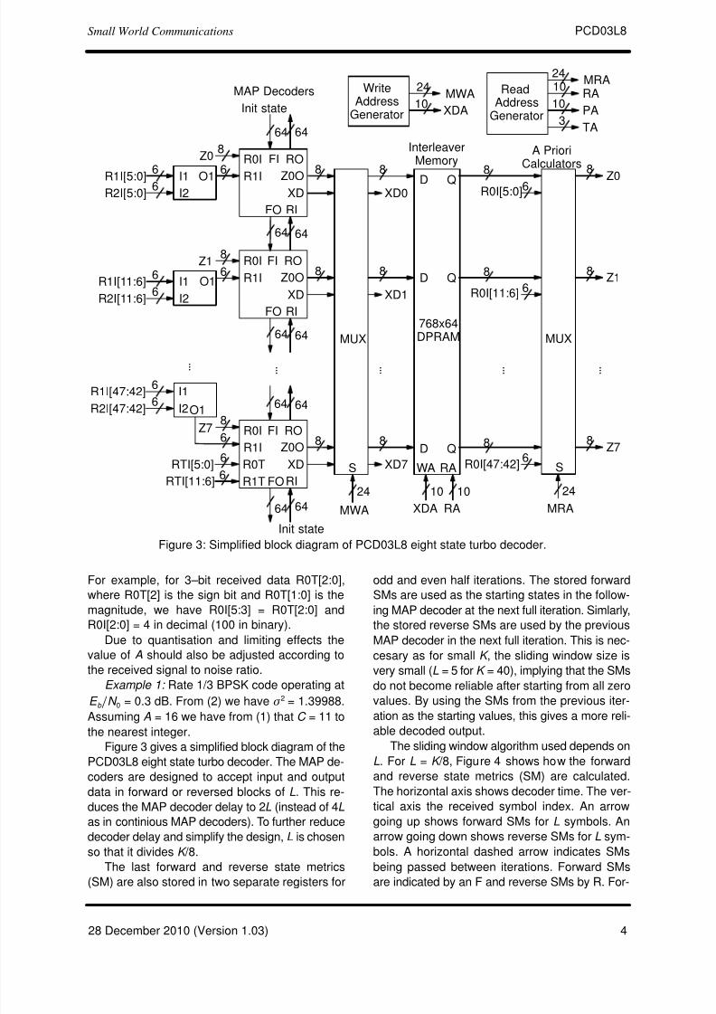
Figure 3: Simplified block diagram of PCD03L8 eight state turbo decoder.
768x64DPRAM
XDR1I
R0IA Priori
Calculators
ReadAddress
Generator
Z0OO1
64
L
Init state
64
XD
R1I
R0I
Z0O
64 64
XD
R1I
R0I
Z0O
FI
FO
64
RI
RO
6464
64
64
64
Init state
6
Z1
O16
8
Z7
O1
6
8
L
8
MUX
8
8
8
S
24
MRA
L
XD0
XD1
XD7
8Z0
MAP Decoders
8
8
8Z0
InterleaverMemory
8Z1
D Q
WA RA
8 Z7
XDA
10
RA
10
2410
MRAWrite
AddressGenerator
8
MUX
S
24
MWA
8
8
L
RA10
PA10
24MWA
D
D
Q
Q
RTI[5:0]
XDA
FI
FO RI
RO
FI
FO RI
RO
6
6
R1T
R0T
6R1I[5:0] I16R2I[5:0] I2
6R1I[11:6] I1
6R2I[11:6] I2
RTI[11:6]
6R1I[47:42] I1
6R2I[47:42] I2
3TA
R0I[11:6] 6
R0I[47:42]6
L
For example, for 3–bit received data R0T[2:0],
where R0T[2] is the sign bit and R0T[1:0] is the
magnitude, we have R0I[5:3] = R0T[2:0] and
R0I[2:0] = 4 in decimal (100 in binary).
Due to quantisation and limiting effects the
value of A should also be adjusted according to
the received signal to noise ratio.
Example 1: Rate 1/3 BPSK code operating at
E b
ńN 0 = 0.3 dB. From (2) we have s
2 = 1.39988.
Assuming A = 16 we have from (1) that C = 11 to
the nearest integer.
Figure 3 gives a simplified block diagram of the
PCD03L8 eight state turbo decoder. The MAP de-
coders are designed to accept input and output
data in forward or reversed blocks of L. This re-
duces the MAP decoder delay to 2L (instead of 4L
as in continious MAP decoders). To further reduce
decoder delay and simplify the design, L is chosen
so that it divides K /8.
The last forward and reverse state metrics
(SM) are also stored in two separate registers for
odd and even half iterations. The stored forward
SMs are used as the starting states in the follow-
ing MAP decoder at the next full iteration. Simlarly,
the stored reverse SMs are used by the previous
MAP decoder in the next full iteration. This is nec-
cesary as for small K , the sliding window size is
very small (L = 5 for K = 40), implying that the SMs
do not become reliable after starting from all zero
values. By using the SMs from the previous iter-
ation as the starting values, this gives a more reli-
able decoded output.
The sliding window algorithm used depends on
L. For L = K /8, Figure 4 shows how the forward
and reverse state metrics (SM) are calculated.
The horizontal axis shows decoder time. The ver-
tical axis the received symbol index. An arrow
going up shows forward SMs for L symbols. An
arrow going down shows reverse SMs for L sym-
bols. A horizontal dashed arrow indicates SMs
being passed between iterations. Forward SMs
are indicated by an F and reverse SMs by R. For-

7/28/2019 pcd03l8
http://slidepdf.com/reader/full/pcd03l8 5/13
7/28/2019 pcd03l8
http://slidepdf.com/reader/full/pcd03l8 6/13
PCD03L8Small World Communications
628 December 2010 (Version 1.03)
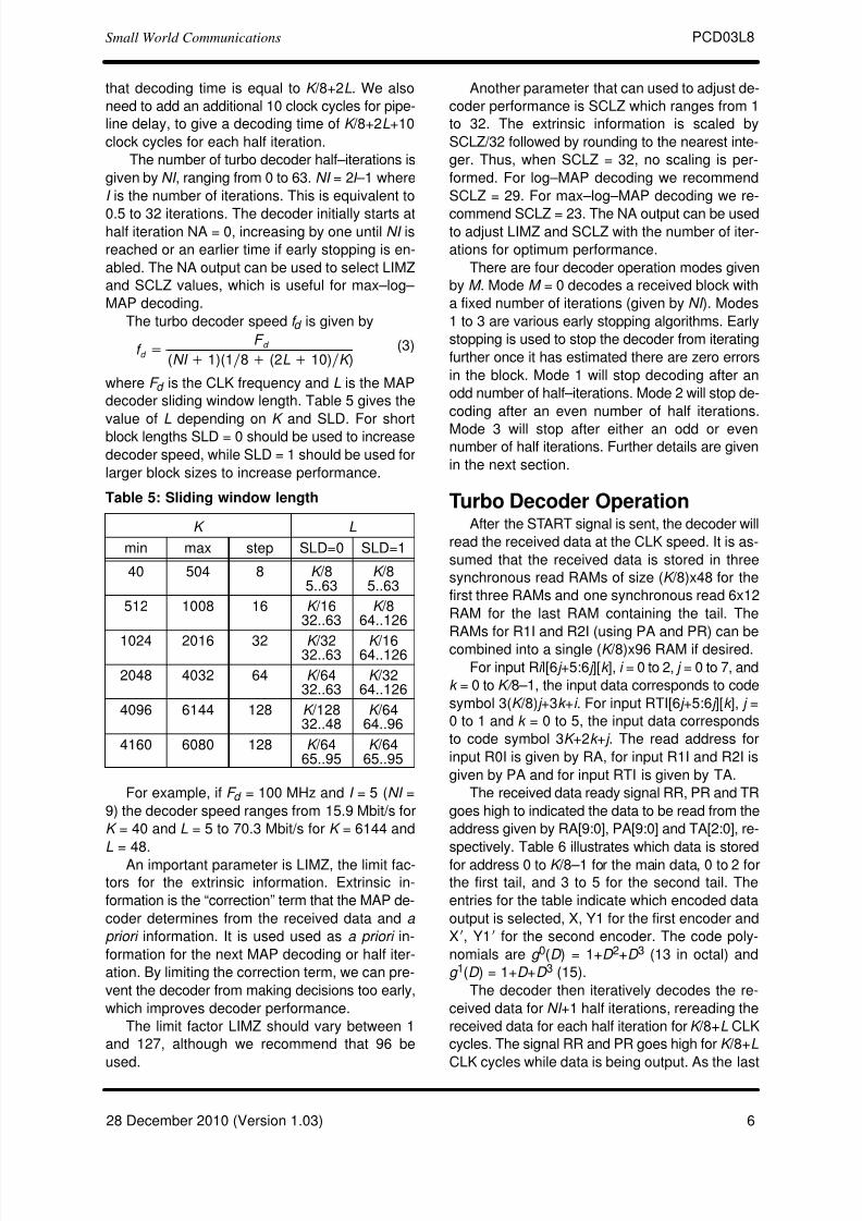
that decoding time is equal to K /8+2L. We also
need to add an additional 10 clock cycles for pipe-
line delay, to give a decoding time of K /8+2L+10
clock cycles for each half iteration.
The number of turbo decoder half–iterations is
given by NI , ranging from 0 to 63. NI = 2I –1 where
I is the number of iterations. This is equivalent to
0.5 to 32 iterations. The decoder initially starts athalf iteration NA = 0, increasing by one until NI is
reached or an earlier time if early stopping is en-
abled. The NA output can be used to select LIMZ
and SCLZ values, which is useful for max–log–
MAP decoding.
The turbo decoder speed f d is given by
f d +F d
(NI ) 1)(1ń8 ) (2L ) 10)ńK )(3)
where F d is the CLK frequency and L is the MAP
decoder sliding window length. Table 5 gives the
value of L depending on K and SLD. For short
block lengths SLD = 0 should be used to increase
decoder speed, while SLD = 1 should be used for
larger block sizes to increase performance.
Table 5: Sliding window length
K L
min max step SLD=0 SLD=1
40 504 8 K /85..63
K /85..63
512 1008 16 K /1632..63
K /864..126
1024 2016 32 K /3232..63
K /1664..126
2048 4032 64 K /6432..63
K /3264..126
4096 6144 128 K /12832..48
K /6464..96
4160 6080 128 K /6465..95
K /6465..95
For example, if F d = 100 MHz and I = 5 (NI =
9) the decoder speed ranges from 15.9 Mbit/s for
K = 40 and L = 5 to 70.3 Mbit/s for K = 6144 and
L = 48.
An important parameter is LIMZ, the limit fac-
tors for the extrinsic information. Extrinsic in-
formation is the “correction” term that the MAP de-
coder determines from the received data and a
priori information. It is used used as a priori in-
formation for the next MAP decoding or half iter-
ation. By limiting the correction term, we can pre-
vent the decoder from making decisions too early,
which improves decoder performance.
The limit factor LIMZ should vary between 1
and 127, although we recommend that 96 be
used.
Another parameter that can used to adjust de-
coder performance is SCLZ which ranges from 1
to 32. The extrinsic information is scaled by
SCLZ/32 followed by rounding to the nearest inte-
ger. Thus, when SCLZ = 32, no scaling is per-
formed. For log–MAP decoding we recommend
SCLZ = 29. For max–log–MAP decoding we re-
commend SCLZ = 23. The NA output can be usedto adjust LIMZ and SCLZ with the number of iter-
ations for optimum performance.
There are four decoder operation modes given
by M . Mode M = 0 decodes a received block with
a fixed number of iterations (given by NI ). Modes
1 to 3 are various early stopping algorithms. Early
stopping is used to stop the decoder from iterating
further once it has estimated there are zero errors
in the block. Mode 1 will stop decoding after an
odd number of half–iterations. Mode 2 will stop de-
coding after an even number of half iterations.
Mode 3 will stop after either an odd or evennumber of half iterations. Further details are given
in the next section.
Turbo Decoder OperationAfter the START signal is sent, the decoder will
read the received data at the CLK speed. It is as-
sumed that the received data is stored in three
synchronous read RAMs of size (K /8)x48 for the
first three RAMs and one synchronous read 6x12
RAM for the last RAM containing the tail. The
RAMs for R1I and R2I (using PA and PR) can be
combined into a single (K /8)x96 RAM if desired.
For input Ri I[6 j +5:6 j ][k ], i = 0 to 2, j = 0 to 7, and
k = 0 to K/ 8–1, the input data corresponds to code
symbol 3(K /8) j +3k +i . For input RTI[6 j +5:6 j ][k ], j =
0 to 1 and k = 0 to 5, the input data corresponds
to code symbol 3K +2k + j . The read address for
input R0I is given by RA, for input R1I and R2I is
given by PA and for input RTI is given by TA.
The received data ready signal RR, PR and TR
goes high to indicated the data to be read from the
address given by RA[9:0], PA[9:0] and TA[2:0], re-
spectively. Table 6 illustrates which data is stored
for address 0 to K /8–1 for the main data, 0 to 2 for
the first tail, and 3 to 5 for the second tail. The
entries for the table indicate which encoded data
output is selected, X, Y1 for the first encoder and
Xi, Y1i for the second encoder. The code poly-
nomials are g 0(D ) = 1+D 2+D 3 (13 in octal) and
g 1(D ) = 1+D +D 3 (15).
The decoder then iteratively decodes the re-
ceived data for NI +1 half iterations, rereading the
received data for each half iteration for K /8+L CLK
cycles. The signal RR and PR goes high for K /8+L
CLK cycles while data is being output. As the last

7/28/2019 pcd03l8
http://slidepdf.com/reader/full/pcd03l8 7/13
PCD03L8Small World Communications
728 December 2010 (Version 1.03)
input RAM has the tail, a separate read address
TA and read ready TR signals are used. TR goes
high for 3 CLK cycles to read the tail.
Table 6: Input data format
Rate Data Main Tail 1 Tail 2
1/3 R0I[47:0] X
R1I[47:0] Y1
R2I[47:0] Y1i
RTI[5:0] X Xi
RTI[11:6] Y1 Y1i
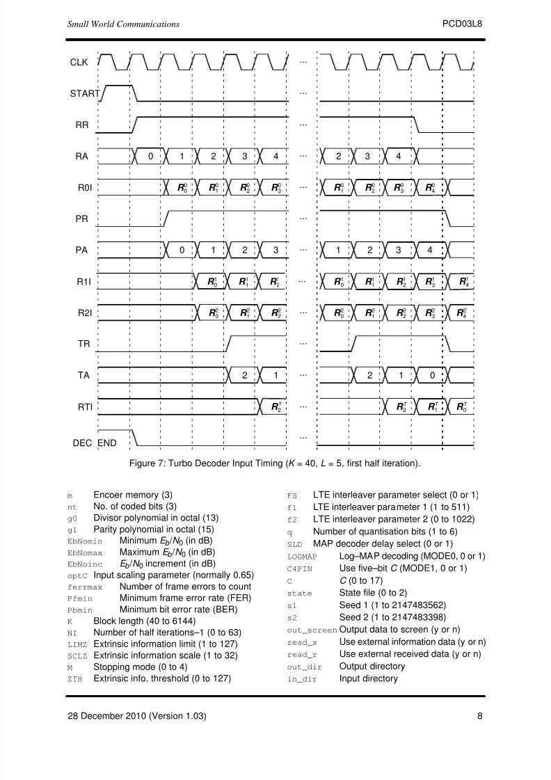
Figure 7 illustrates the decoder timing where
the data is input during the first half iteration. The
input R i k , for i = 0 to 2 and k = 0 to K /8–1 corres-
ponds to input data Ri I[47:0][k ]. The input R T k for
k = 0 to 5 corresponds to RTI[11:0][k ].
Note that while DEC_END is low (decoding is
being performed), the START signal is ignored,
except for the last clock cycle before DEC_END
goes high. A synchronous reset is also provided.
All flip flops in the turbo decoder are reset during
a low to high transition of CLK while RST is high.
The decoded data is output during the last
half–iteration on XD[7:0]. That is, decoded data is
output 8–bits every CLK cycle. The signal XDR
goes high for K /8 CLK cycles while the block is
output. If NI is even (odd half iterations), the block
is output in reverse block sequential order. To der-
everse the decoded data, the output XDA[9:0]
needs to be used as the write address to a buffer
RAM.
For NI odd (even half iterations), the block is
output in reverse block interleaved order. To der-
everse and deinterleave the block, the output
XDA[9:0] is used as the write address to a buffer
RAM.
The bus ERR[7:0] is a channel error estimator
output. It is the exclusive OR of XD[7:0] and the
sign bits of R0I[47:0], i.e., bit R0I[6 j +5] for j = 0 to
7.
The bus MAG[7:0] is the input data magnitude
indicator. For R0I[6 j +5:6 j ] for j = 0 to 7, MAG[ j ] is
zero if R0I[6 j +4:6 j ] = 0, otherwise MAG[ j ] is one.
For example if R0I[5:0] = 16 then MAG[0] = 1. If
R0I[5:0] = 0 or R0I[5:0] = 32 then MAG[0] = 0.
The MAG[7:0] outputs can be used to erase
ERR[7:0] outputs when input data R0I[6 j +4:6 j ] is
erased. This avoids counting errors where the
input sign is unknown. For example, say non–er-
ased data has a minimum input magnitude of one.
If R0I[5:0] has its magnitude erased, i.e., R0I[4:0]
is zero, then by using the operation ERR[0] AND
MAG[0], we can delete this estimated error.
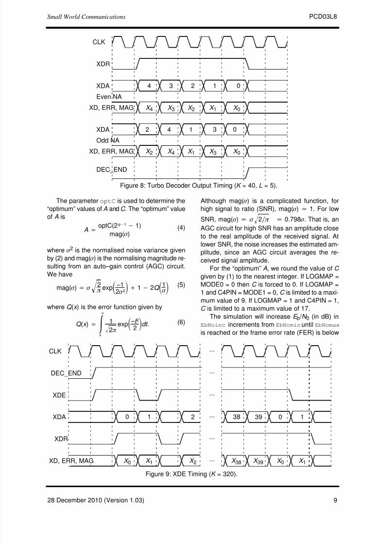
The DEC_END signal is low during decoding.
At the end of decoding, DEC_END goes high. Fig-
ure 8 illustrates the decoder timing where data is
output on the last half iteration. After startup, the
maximum number of clock cycles for decoding is
(NI +1)(K /8+2L+10).
During the last half iteration the decoded and
error data are stored into the interleaver memory.Once decoding has been completed, the input
XDE can be used to sequentially clock the de-
coded and error data from from the interleaver
memory (regardless of the number of iterations).
XDE is disabled while the decoder is iterating. Fig-
ure 9 shows the decoder timing when XDE is
used.
The early stopping algorithm uses the magni-
tude of the extrinsic information to determine
when to stop. As the decoder iterates, the magni-
tudes generally increases in value as the decoder
becomes more confident in its decision. By com-paring the smallest magnitude of a block with thre-
shold ZTH, we can decide when to stop. If the
smallest magnitude is greater than ZTH, i.e., not
equal or less than ZTH, the decoder will stop iter-
ating if early stopping has been enabled.
Since the last half iteration is used to store the
decoded data into the interleaver memory, the de-
coder performs an extra half iteration once the
threshold has been exceeded.
Increasing ZTH will increase the average
number of iterations and decrease the BER. De-
creasing ZTH will decrease the average numberof iterations and increase the BER. In general,
higher values of SNR will decrease the number of
iterations. A value of ZTH = 23 was found to give
a good trade off between the average number of
iterations and BER performance.
For high SNR operation early stopping can
lead to significantly reduced power consumption,
since most blocks will be decoded in one or two
iterations.
Simulation SoftwareFree software for simulating the PCD03L8
turbo decoder in additive white Gaussian noise
(AWGN) or with external data is available by
sending an email to [email protected] with
“pcd03l8sim request” in the subject header. The
software uses an exact functional simulation of
the PCD03L8 turbo decoder, including all quan-
tisation and limiting effects.
After unzipping pcd03l8sim.zip, there should
be pcd03l8sim.exe and code03l8.txt. The file
code03l8.txt contains the parameters for running
pcd03l8sim. These parameters are
7/28/2019 pcd03l8
http://slidepdf.com/reader/full/pcd03l8 8/13
PCD03L8Small World Communications
828 December 2010 (Version 1.03)
CLK
Figure 7: Turbo Decoder Input Timing (K = 40, L = 5, first half iteration).
RR
RA 1 20 2
R0I
3 3 4
...
...
...
...
...
...DEC_END
START
R1I ...
RTI...
TR
TA
...
... 1 02
R 00 R
01 R
02 R
01 R
02 R
03 R
04
R 10 R
11 R
12 R
10 R
11 R
12 R
13
R T
2R
T
1R
T
0
4
R 03
PR
PA 1 20 1 2
R2I
3 3 4
...
...
...R 20 R
21 R
22 R
20 R
21 R
22 R
23 R
24
R 14
12
R T
2
m Encoer memory (3)
nt No. of coded bits (3)
g0 Divisor polynomial in octal (13)
g1 Parity polynomial in octal (15)
EbNomin Minimum E b / N
0(in dB)
EbNomax Maximum E b / N 0 (in dB)
EbNoinc E b / N 0 increment (in dB)
optC Input scaling parameter (normally 0.65)
ferrmax Number of frame errors to count
Pfmin Minimum frame error rate (FER)
Pbmin Minimum bit error rate (BER)
K Block length (40 to 6144)
NI Number of half iterations–1 (0 to 63)
LIMZ Extrinsic information limit (1 to 127)
SCLZ Extrinsic information scale (1 to 32)
M Stopping mode (0 to 4)
ZTH Extrinsic info. threshold (0 to 127)
FS LTE interleaver parameter select (0 or 1)
f1 LTE interleaver parameter 1 (1 to 511)
f2 LTE interleaver parameter 2 (0 to 1022)
q Number of quantisation bits (1 to 6)
SLD MAP decoder delay select (0 or 1)LOGMAP Log–MAP decoding (MODE0, 0 or 1)
C4PIN Use five–bit C (MODE1, 0 or 1)
C C (0 to 17)
state State file (0 to 2)
s1 Seed 1 (1 to 2147483562)
s2 Seed 2 (1 to 2147483398)
out_screen Output data to screen (y or n)
read_x Use external information data (y or n)
read_r Use external received data (y or n)
out_dir Output directory
in_dir Input directory
7/28/2019 pcd03l8
http://slidepdf.com/reader/full/pcd03l8 9/13
PCD03L8Small World Communications
928 December 2010 (Version 1.03)
CLK
Figure 8: Turbo Decoder Output Timing (K = 40, L = 5).
XDR
XDA 3 24 0
X 4
1
X 3 X 2 X 1 X 0
Even NA
XDA 4 12 0
X 2
3
X 4 X 1 X 3 X 0
Odd NA
DEC_END
XD, ERR, MAG
XD, ERR, MAG
The parameter optC is used to determine the
“optimum” values of A and C . The “optimum” value
of A is
A +optC(2q *1 * 1)
mag( s )(4)
where s 2 is the normalised noise variance given
by (2) and mag( s ) is the normalising magnitude re-
sulting from an auto–gain control (AGC) circuit.
We have
mag( s ) + s 2 pǸ expǒ –12 s 2Ǔ ) 1 * 2Q ǒ1 s Ǔ (5)
where Q (x ) is the error function given by
Q (x ) + ŕR
x
1
2 pǸ expǒ – t 2
2Ǔdt . (6)
Although mag( s ) is a complicated function, for
high signal to ratio (SNR), mag( s ) ] 1. For low
SNR, mag( s ) ] s 2ń pǸ ] 0.798 s . That is, an
AGC circuit for high SNR has an amplitude close
to the real amplitude of the received signal. At
lower SNR, the noise increases the estimated am-
plitude, since an AGC circuit averages the re-
ceived signal amplitude.
For the “optimum” A, we round the value of C
given by (1) to the nearest integer. If LOGMAP =
MODE0 = 0 then C is forced to 0. If LOGMAP =1 and C4PIN = MODE1 = 0, C is limited to a maxi-
mum value of 9. If LOGMAP = 1 and C4PIN = 1,
C is limited to a maximum value of 17.
The simulation will increase E b / N 0 (in dB) in
EbNoinc increments from EbNomin until EbNomax
is reached or the frame error rate (FER) is below
CLK
Figure 9: XDE Timing (K = 320).
XDE
XDA 0 1 38 39
XDR
X 0
0 1
...
...
...
...
...DEC_END
2
X 1 X 2 X 38 X 39 X 0 X 1
...
XD, ERR, MAG
7/28/2019 pcd03l8
http://slidepdf.com/reader/full/pcd03l8 10/13
PCD03L8Small World Communications
1028 December 2010 (Version 1.03)
or equal to Pfmin or the bit error rate (BER) is
below or equal to Pbmin. Each simulation point
continues until the number of frame errors is equal
to ferrmax. If ferrmax= 0, then only one frame is
simulated.
When the simulation is finished the output is
given in, for example, file k512.dat, where K = 512.
Only frames that are in error are stored in the out-put file. The first line gives the E b / N 0 (Eb/No), the
number of frames (num), the number of bit errors
in the frame (err), the total number of bit errors
(berr), the total number of frame errors (ferr),
the average number of iterations (na), the average
BER (Pb) and the average FER (Pf). Following
this, the number of iterations, na, berr, ferr, Pb,
and Pf are given for each half iteration.
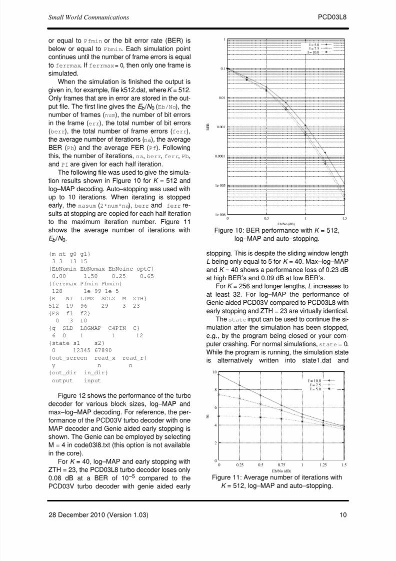
The following file was used to give the simula-
tion results shown in Figure 10 for K = 512 and
log–MAP decoding. Auto–stopping was used with
up to 10 iterations. When iterating is stoppedearly, the nasum (2*num*na), berr and ferr re-
sults at stopping are copied for each half iteration
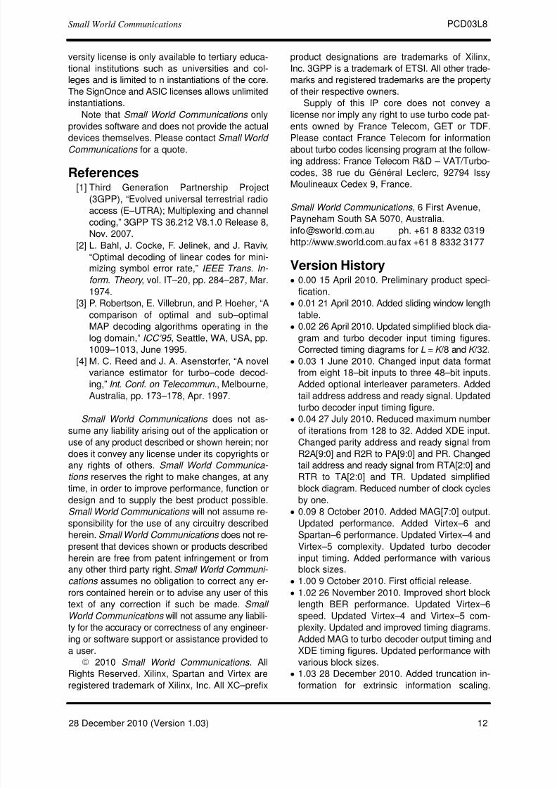
to the maximum iteration number. Figure 11
shows the average number of iterations with
E b / N 0.
{m nt g0 g1}
3 3 13 15
{EbNomin EbNomax EbNoinc optC}
0.00 1.50 0.25 0.65
{ferrmax Pfmin Pbmin}
128 1e–99 1e–5
{K NI LIMZ SCLZ M ZTH}
512 19 96 29 3 23
{FS f1 f2}
0 3 10
{q SLD LOGMAP C4PIN C}
6 0 1 1 12
{state s1 s2}
0 12345 67890
{out_screen read_x read_r}
y n n
{out_dir in_dir}
output input
Figure 12 shows the performance of the turbodecoder for various block sizes, log–MAP and
max–log–MAP decoding. For reference, the per-
formance of the PCD03V turbo decoder with one
MAP decoder and Genie aided early stopping is
shown. The Genie can be employed by selecting
M = 4 in code03l8.txt (this option is not available
in the core).
For K = 40, log–MAP and early stopping with
ZTH = 23, the PCD03L8 turbo decoder loses only
0.08 dB at a BER of 10 –5 compared to the
PCD03V turbo decoder with genie aided early
Figure 10: BER performance with K = 512,
log–MAP and auto–stopping.
1e-006
1e-005
0.0001
0.001
0.01
0.1
1
0 0.5 1 1.5
B E R
Eb/No (dB)
I = 5.0I = 7.5
I = 10.0
stopping. This is despite the sliding window length
L being only equal to 5 for K = 40. Max–log–MAP
and K = 40 shows a performance loss of 0.23 dB
at high BER’s and 0.09 dB at low BER’s.
For K = 256 and longer lengths, L increases to
at least 32. For log–MAP the performance ofGenie aided PCD03V compared to PCD03L8 with
early stopping and ZTH = 23 are virtually identical.
The state input can be used to continue the si-
mulation after the simulation has been stopped,
e.g., by the program being closed or your com-
puter crashing. For normal simulations, state = 0.
While the program is running, the simulation state
is alternatively written into state1.dat and
Figure 11: Average number of iterations with
K = 512, log–MAP and auto–stopping.
0
2
4
6
8
10
0 0.25 0.5 0.75 1 1.25 1.5
n a
Eb/No (dB)
I = 10.0I = 7.5I = 5.0

7/28/2019 pcd03l8
http://slidepdf.com/reader/full/pcd03l8 11/13
PCD03L8Small World Communications
1128 December 2010 (Version 1.03)
Figure 12: Performance with various block sizes, auto–stopping (Genie and
ZTH = 23), log–MAP (SCLZ=29) and max–log–MAP (SCLZ=23).
1e-006
1e-005
0.0001
0.001
0.01
0.1
1
0 0.5 1 1.5 2 2.5 3 3.5 4 4.5
B E R
Eb/No (dB)
K = 40 PCD03L8 (Max-log-MAP)K = 40 PCD03L8 (log-MAP)
K = 40 PCD03V (log-MAP, Genie)K = 256 PCD03L8 (Max-log-MAP)
K = 256 PCD03L8 (log-MAP)K = 256 PCD03V (log-MAP, Genie)K = 512 PCD03L8 (Max-log-MAP)
K = 512 PCD03L8 (log-MAP)K = 512 PCD03V (log-MAP, Genie)K = 1024 PCD03L8 (Max-log-MAP)
K = 1024 PCD03L8 (log-MAP)K = 1024 PCD03V (log-MAP, Genie)
state2.dat. Two state files are used in case the
program stops while writing data into one file. To
continue the simulation after the program is
stopped follow these instructions:
1) Copy the state files state1.dat and state2.dat.This ensures you can restart the program if a mis-
take is made in configuring code03l8.txt.
2) Examine the state files and choose one that
isn’t corrupted.
3) Change the state parameter to 1 if state1.dat is
used or 2 if state2.dat is used.
4) Restart the simulation. The output will be ap-
pended to the existing k(K).dat file.
5) After the simulation has been completed, make
sure that state is changed back to 0.
The software can also be used to encode and
decode external data. To encode a block
x_(K).dat in the directory given by in_dir, set
read_x to y, e.g., x_512.dat in directory input
(each line contains one bit of data). The encoded
stream y_(K).datwill be output to the directory
given by out_dir, e.g., y_512.dat to directory
output.
To decode data, place the received block of
data in file r_(K).dat in directory in_dir and set
read_r to y. The decoded data is output to
xd_(K).dat in directory out_dir. r_(K).dat has
in each line R[i,j], i = 0 to nt–1 from j = 0 to K –1 and
i = 0 to n–1 from j = K to K +2m –1, e.g., for nt = 3
the first three lines could be
–31 1 –25
–31 12 911 31 31
The input data is of the form
R[i,j] = A*(1–2*Y[i,j]+N[i,j])
where A is the signal amplitude, Y[i,j] is the coded
bit, and N[i,j] is white Gaussian noise with zero
mean and normalised variance s 2. The magnitude
of R[i,j] should be rounded to the nearest integer
and be no greater than 2q–1 –1. If read_r= y, then
C is externally input via C.
Ordering InformationSW–PCD03L8–SOS (SignOnce Site License)
SW–PCD03L8–SOP (SignOnce Project License)
SW–PCD03L8–VHD (VHDL ASIC License)
SW–PCD03L8–UNI–n (University License)
All licenses include EDIF and VHDL cores.
The VHDL cores can only be used for simulation
in the SignOnce and University licenses. The Uni-
7/28/2019 pcd03l8
http://slidepdf.com/reader/full/pcd03l8 12/13
PCD03L8Small World Communications
1228 December 2010 (Version 1.03)
versity license is only available to tertiary educa-
tional institutions such as universities and col-
leges and is limited to n instantiations of the core.
The SignOnce and ASIC licenses allows unlimited
instantiations.
Note that Small World Communications only
provides software and does not provide the actual
devices themselves. Please contact Small World Communications for a quote.
References[1] Third Generation Partnership Project
(3GPP), “Evolved universal terrestrial radio
access (E–UTRA); Multiplexing and channel
coding,” 3GPP TS 36.212 V8.1.0 Release 8,
Nov. 2007.
[2] L. Bahl, J. Cocke, F. Jelinek, and J. Raviv,
“Optimal decoding of linear codes for mini-
mizing symbol error rate,” IEEE Trans. In-
form. Theory , vol. IT–20, pp. 284–287, Mar.
1974.
[3] P. Robertson, E. Villebrun, and P. Hoeher, “A
comparison of optimal and sub–optimal
MAP decoding algorithms operating in the
log domain,” ICC’95 , Seattle, WA, USA, pp.
1009–1013, June 1995.
[4] M. C. Reed and J. A. Asenstorfer, “A novel
variance estimator for turbo–code decod-
ing,” Int. Conf. on Telecommun., Melbourne,
Australia, pp. 173–178, Apr. 1997.
Small World Communications does not as-
sume any liability arising out of the application or
use of any product described or shown herein; nor
does it convey any license under its copyrights or
any rights of others. Small World Communica-
tions reserves the right to make changes, at any
time, in order to improve performance, function or
design and to supply the best product possible.
Small World Communications will not assume re-
sponsibility for the use of any circuitry described
herein. Small World Communications does not re-
present that devices shown or products described
herein are free from patent infringement or from
any other third party right. Small World Communi-
cations assumes no obligation to correct any er-
rors contained herein or to advise any user of this
text of any correction if such be made. Small
World Communications will not assume any liabili-
ty for the accuracy or correctness of any engineer-
ing or software support or assistance provided to
a user.
E 2010 Small World Communications . All
Rights Reserved. Xilinx, Spartan and Virtex are
registered trademark of Xilinx, Inc. All XC–prefix
product designations are trademarks of Xilinx,
Inc. 3GPP is a trademark of ETSI. All other trade-
marks and registered trademarks are the property
of their respective owners.
Supply of this IP core does not convey a
license nor imply any right to use turbo code pat-
ents owned by France Telecom, GET or TDF.
Please contact France Telecom for informationabout turbo codes licensing program at the follow-
ing address: France Telecom R&D – VAT/Turbo-
codes, 38 rue du Général Leclerc, 92794 Issy
Moulineaux Cedex 9, France.
Small World Communications , 6 First Avenue,
Payneham South SA 5070, Australia.
[email protected] ph. +61 8 8332 0319
http://www.sworld.com.au fax +61 8 8332 3177
Version History 0.00 15 April 2010. Preliminary product speci-
fication.
0.01 21 April 2010. Added sliding window length
table.
0.02 26 April 2010. Updated simplified block dia-
gram and turbo decoder input timing figures.
Corrected timing diagrams for L = K /8 and K /32.
0.03 1 June 2010. Changed input data format
from eight 18–bit inputs to three 48–bit inputs.
Added optional interleaver parameters. Added
tail address address and ready signal. Updated
turbo decoder input timing figure.
0.04 27 July 2010. Reduced maximum number
of iterations from 128 to 32. Added XDE input.
Changed parity address and ready signal from
R2A[9:0] and R2R to PA[9:0] and PR. Changed
tail address and ready signal from RTA[2:0] and
RTR to TA[2:0] and TR. Updated simplified
block diagram. Reduced number of clock cycles
by one.
0.09 8 October 2010. Added MAG[7:0] output.
Updated performance. Added Virtex–6 and
Spartan–6 performance. Updated Virtex–4 and
Virtex–5 complexity. Updated turbo decoder
input timing. Added performance with various
block sizes.
1.00 9 October 2010. First official release.
1.02 26 November 2010. Improved short block
length BER performance. Updated Virtex–6
speed. Updated Virtex–4 and Virtex–5 com-
plexity. Updated and improved timing diagrams.
Added MAG to turbo decoder output timing and
XDE timing figures. Updated performance with
various block sizes.
1.03 28 December 2010. Added truncation in-
formation for extrinsic information scaling.

7/28/2019 pcd03l8
http://slidepdf.com/reader/full/pcd03l8 13/13
PCD03L8Small World Communications
1328 December 2010 (Version 1.03)
Changed parameter file for pcd03l8sim.exe
from pcd03l8.txt to code03l8.txt.


