Embed Size (px)
Citation preview
International Student Design Competition for Inspiration Mars
Mission Report Summary (Team Kanau)
Shota Iino1, Kshitij Mall2, Ayako Ono3, Jeff Stuart2, Ashwati Das2, Eriko Moriyama4, Takuya
Ohgi5, Nick Gillin6, Koki Tanaka1, Yuri Aida1, Max Fagin2, Daichi Nakajima7
Professor Hiroyuki Miyajima8, Assistant Professor Michael Grant2
1Keio University (Japan), 2Purdue University (USA), 3Tohoku University Graduate School of
Medicine (Alumnus, Japan), 4International Space University (Alumnus, France), 5Nagoya
University (Alumnus, Japan), 6Art Center College of Design (USA), 7Tokyo University of
Agriculture and Technology (Japan), 8Tokyo Jogakkan College (Japan).
TEAM KANAU
1
Table of Contents Abstract 1
1. Mission Objectives 1
2. Mission Design 1
2.1 Mission Design Methods 1
2.2 Requirements Generation 2
2.3 Concept Generation 8
2.4 Concept Selection 9
3. Concept of Operations 9
4. Trajectory Design and Launch Vehicle Selection 11
4.1 Overview 11
4.2 Interplanetary Ballistic Free-Return Trajectory 11
4.3 Earth Launch to LEO 13
5. Aerocapture 16
5.1 Sample Analysis 16
5.2 Results 17
6. Key Subsystem Architecture 18
6.1 Environment Control and Life Support System 18
6.2 Kanau Spacecraft’s Interior Design 24
6.3 Facilities for Crew Physical Health 26
6.4 Facilities for Radiation Protection 27
6.5 Command and Data Handling 27
6.6 Communications 29
6.7 Power Systems 31
6.8 Thermal Control System 36
6.9 Payload Mission 37
7. Safety Analysis and Design 38
7.1 Safety Requirements 38
7.2 Abort Options 39
7.3 Risk Acceptability 39
7.4 Risk Assessment 41
8. Crew Selection from US Astronauts 41
9. Conclusion 43
10. Kanau Team Workflow, Website and Animation Video 43
11. Acknowledgements 44
12. References 45
Appendix A 47
Appendix B 50
Appendix C 55
Table of Figures Figure 1 Process for mission design. 2 Figure 2 Whats of House of Quality. 3 Figure 3 Importance Ratings of Requirements. 4 Figure 4 Hows of House of Quality. 5 Figure 5 Direction of improvement over Inspiration Mars baseline. 5 Figure 6 Relationship matrix. 6 Figure 7 Target and threshold values for hows of the House of Quality. 6 Figure 8 Correlation matrix. 7
TEAM KANAU
2
Figure 9 Absolute and relative importance of hows of the House of Quality. 7 Figure 10 Ranking of the hows of House of Quality. 8 Figure 11 Morphological chart. 9 Figure 12 Concept of operations. 10 Figure 13 Vehicle stack before TMI. 11 Figure 14 Ballistic free-return trajectory with Earth departure in January 2018, Mars flyby in August 2018, and
Earth return in May 2019. 12 Figure 15 Earth departure and staging orbits. 15
Figure 16 Mars close approach. 15
Figure 17 Earth return and re-entry. 15 Figure 18 Transition from hyperbolic velocity to elliptical capture velocity. 16 Figure 19 Various Earth-capture ellipses after performing aerocapture. 16 Figure 20 Results: Altitude vs. Periapse Velocity plot for a sample analysis. 18 Figure 21 Functions for each ECLSS management subsystem. 19 Figure 22 A concept of an Algal air revitalization system. 22 Figure 23 Lettuce home cultivation kit. 23 Figure 24 Sample image of SImulator for Closed Life and Ecology, SICLE. 24 Figure 25 Aspects of interior design. 24 Figure 26 Artificial rainbow generated by spotlight. 25 Figure 27 Outline of facilities for crew physical health. 26 Figure 28 Outline of facilities for radiation protection. 27 Figure 29 Various PV geometries. 34 Figure 30 Top-level system architecture. 36 Figure 31 Active and passive thermal control processes. 37 Figure 32 Examples of payload mission. 38 Figure 33 Estimated risk reduction potential per subsystem for human Mars mission. 40 Figure 34 Risk assessment architecture. 41
List of Tables Table 1 Critical epochs of the Earth-Mars-Earth free-return trajectory. ............................................................ 12 Table 2 Velocities and periapse altitudes of the departure, fly-by, and return hyperbolic trajectories. .................... 12 Table 3 Potential launch sites. ................................................................................................................... 13 Table 4 Launch vehicle and upper stage trade analysis, for spacecraft with and without 10% growth margin. ....... 14 Table 5 Launch timeline. .......................................................................................................................... 15 Table 6 Aerocapture sample analysis data. ................................................................................................... 17 Table 7 Results for aerocapture sample analysis. .......................................................................................... 17 Table 8 Material consumption of human crew (kg/Crew Member-day). ........................................................... 20 Table 9 Material production of human crew (kg/CM-day). ............................................................................ 20 Table 10 Modular functions and their configuration for DCDMS. ................................................................... 28 Table 11 C&DH budgets. .......................................................................................................................... 29 Table 12 Communication for a Mars flyby mission. ...................................................................................... 29 Table 13 Data rate requirements for TV. ...................................................................................................... 30 Table 14 TV antennas in a nutshell. ............................................................................................................ 30 Table 15 Contingencies and proposed solutions. .......................................................................................... 30 Table 16 TV communications budget. ......................................................................................................... 31 Table 17 Critical considerations for power system. ....................................................................................... 32 Table 18 Preliminary vehicle power budget. ................................................................................................ 33 Table 19 Safety requirements for Inspiration Mars mission. ........................................................................... 39 Table 20 Abort possibilities. ...................................................................................................................... 39 Table 21 Risk acceptability........................................................................................................................ 40 Table 22 Candidate American astronaut couples list for Inspiration Mars mission. ............................................ 42 Table 23 Major tasks performed by individual team members. ....................................................................... 43 Table 24 Major roles of team’s advisors. ..................................................................................................... 44
TEAM KANAU
1
Abstract
There is strong potential for a near-future, human mission to Mars, with Inspiration Mars and the
Mars Society in particular advocating for a two-person, manned flyby mission within the coming
decade. This document presents team Kanau’s (Kanau, the Japanese word for “collaboration”
and “synergism”, was chosen to symbolize our team members hailing from different universities
of US and Japan) response to the challenge posed by the Mars Society for student groups to plan
a flyby of Mars in the year 2018 by a male and female astronaut pair. Building upon analyses
published by Inspiration Mars, team Kanau investigates in more detail and presents novel
solutions for various aspects of the mission architecture, including: spacecraft design, crew life
support, launch vehicle selection, the flyby trajectory, Earth capture and re-entry. While we
address many key technical aspects, we give particular attention to ensuring the physical, mental,
and psychological health of the two astronauts for the duration of the journey. Specifically,
regenerative air scrubbers, the combination of pre-packaged and grown food, as well as 3-D
printing technology support the human crew during the 501-day flight. A novel combination of a
Falcon Heavy launch to LEO and a ULA ACES-enabled Trans-Mars Injection places the crewed
spacecraft on a free-return trajectory, while aerocapture upon Earth return enables reduction in
the required size of the re-entry heat shield. The technologies and design concepts that we
propose, while requiring further development prior to the stated 2018 mission opportunity, are
powerful enabling factors for the crewed Mars flyby as well as other manned deep space
missions.
1 Mission Objectives
Our mission objective is to design a Mars flyby mission for two crewmembers in 2018 that is
both safe and cost efficient. Any Mars-bound manned spacecraft will be too large to launch in
one attempt, so in order to meet these objectives we desire a small number of assemblages in
outer space.
2 Mission Design
2.1 Mission Design Methods
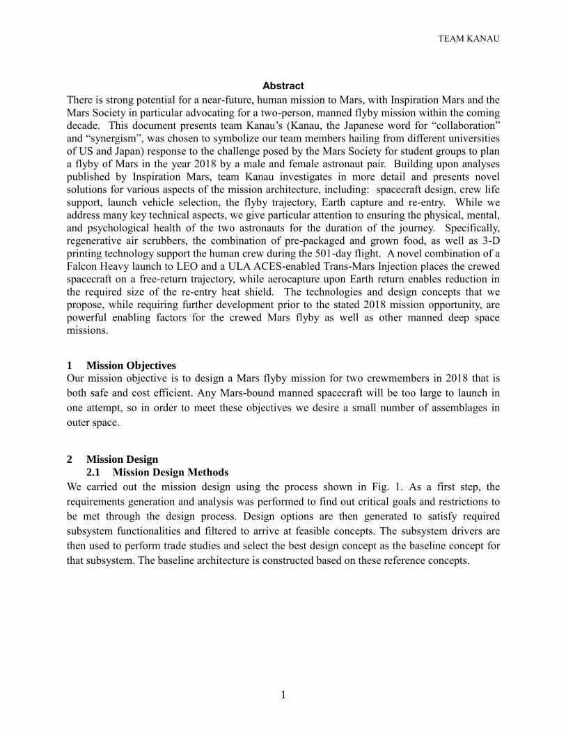
We carried out the mission design using the process shown in Fig. 1. As a first step, the
requirements generation and analysis was performed to find out critical goals and restrictions to
be met through the design process. Design options are then generated to satisfy required
subsystem functionalities and filtered to arrive at feasible concepts. The subsystem drivers are
then used to perform trade studies and select the best design concept as the baseline concept for
that subsystem. The baseline architecture is constructed based on these reference concepts.
TEAM KANAU
2
Figure 1 Process for mission design.
2.2 Requirements Generation (The House of Quality)
To gather requirements, we performed quality functional deployment (QFD). In order to translate
the needs of the mission into technical characteristics and specifications a "House of Quality"1
(HoQ) was constructed using the following steps. Portions of the House of Quality appear as
figures in the following sections. Please refer to Appendix B for the full House of Quality.
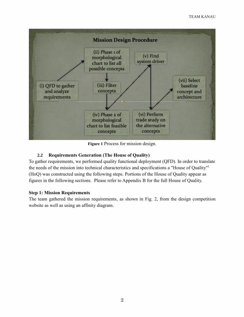
Step 1: Mission Requirements
The team gathered the mission requirements, as shown in Fig. 2, from the design competition
website as well as using an affinity diagram.
TEAM KANAU
3
Figure 2 Whats of House of Quality.
Step 2: Regulatory Requirements
The team documented implicit requirements that are dictated by regulatory standards that the
mission must adhere to.
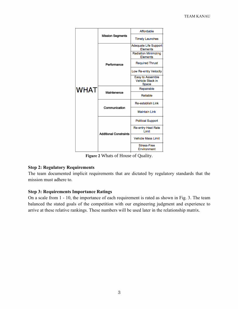
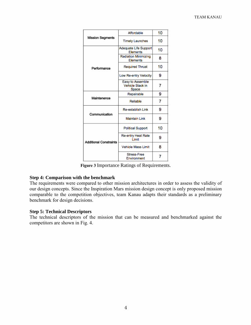
Step 3: Requirements Importance Ratings
On a scale from 1 - 10, the importance of each requirement is rated as shown in Fig. 3. The team
balanced the stated goals of the competition with our engineering judgment and experience to
arrive at these relative rankings. These numbers will be used later in the relationship matrix.
TEAM KANAU
4
Figure 3 Importance Ratings of Requirements.
Step 4: Comparison with the benchmark The requirements were compared to other mission architectures in order to assess the validity of
our design concepts. Since the Inspiration Mars mission design concept is only proposed mission
comparable to the competition objectives, team Kanau adapts their standards as a preliminary
benchmark for design decisions.
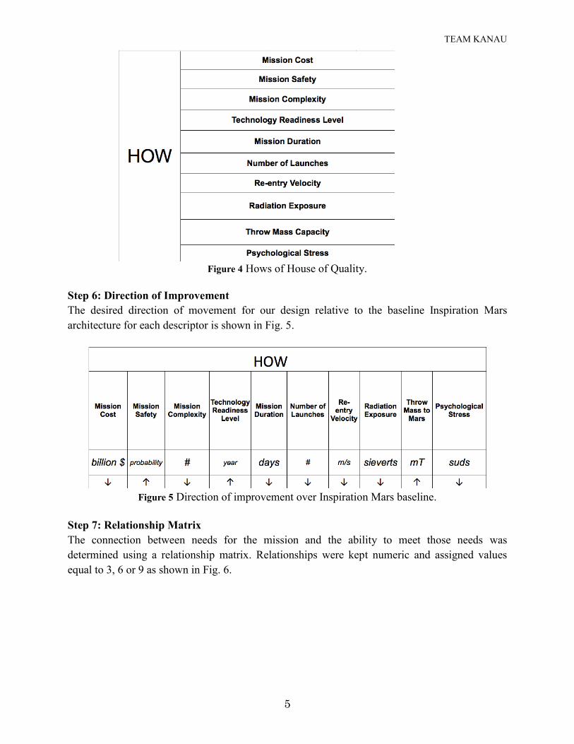
Step 5: Technical Descriptors The technical descriptors of the mission that can be measured and benchmarked against the
competitors are shown in Fig. 4.
TEAM KANAU
5
Figure 4 Hows of House of Quality.
Step 6: Direction of Improvement
The desired direction of movement for our design relative to the baseline Inspiration Mars
architecture for each descriptor is shown in Fig. 5.
Figure 5 Direction of improvement over Inspiration Mars baseline.
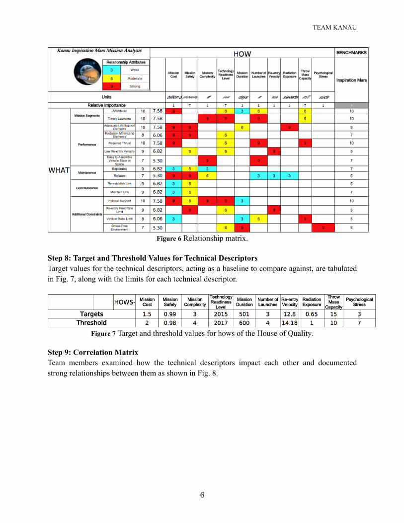
Step 7: Relationship Matrix
The connection between needs for the mission and the ability to meet those needs was
determined using a relationship matrix. Relationships were kept numeric and assigned values
equal to 3, 6 or 9 as shown in Fig. 6.
TEAM KANAU
6
Figure 6 Relationship matrix.
Step 8: Target and Threshold Values for Technical Descriptors
Target values for the technical descriptors, acting as a baseline to compare against, are tabulated
in Fig. 7, along with the limits for each technical descriptor.
Figure 7 Target and threshold values for hows of the House of Quality.
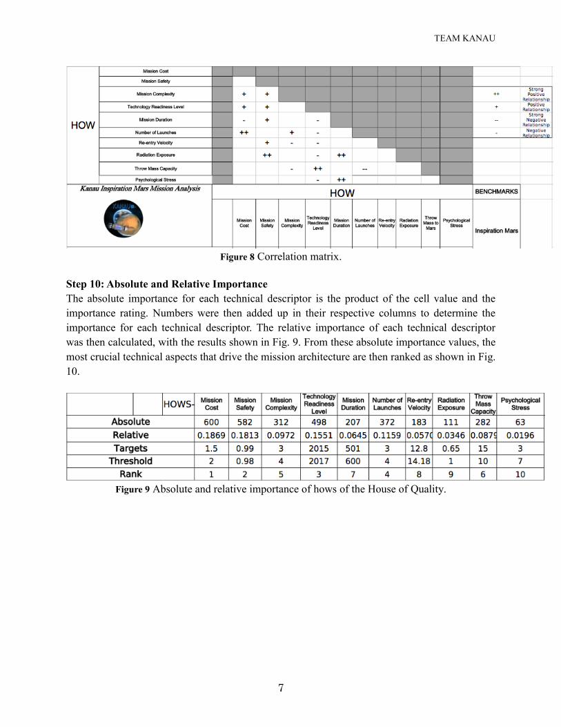
Step 9: Correlation Matrix
Team members examined how the technical descriptors impact each other and documented
strong relationships between them as shown in Fig. 8.
TEAM KANAU
7
Figure 8 Correlation matrix.
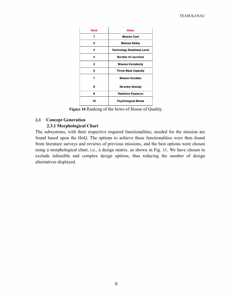
Step 10: Absolute and Relative Importance
The absolute importance for each technical descriptor is the product of the cell value and the
importance rating. Numbers were then added up in their respective columns to determine the
importance for each technical descriptor. The relative importance of each technical descriptor
was then calculated, with the results shown in Fig. 9. From these absolute importance values, the
most crucial technical aspects that drive the mission architecture are then ranked as shown in Fig.
10.
Figure 9 Absolute and relative importance of hows of the House of Quality.
TEAM KANAU
8
Figure 10 Ranking of the hows of House of Quality.
2.3 Concept Generation
2.3.1 Morphological Chart
The subsystems, with their respective required functionalities, needed for the mission are
found based upon the HoQ. The options to achieve these functionalities were then found
from literature surveys and reviews of previous missions, and the best options were chosen
using a morphological chart, i.e., a design matrix, as shown in Fig. 11. We have chosen to
exclude infeasible and complex design options, thus reducing the number of design
alternatives displayed.
TEAM KANAU
9
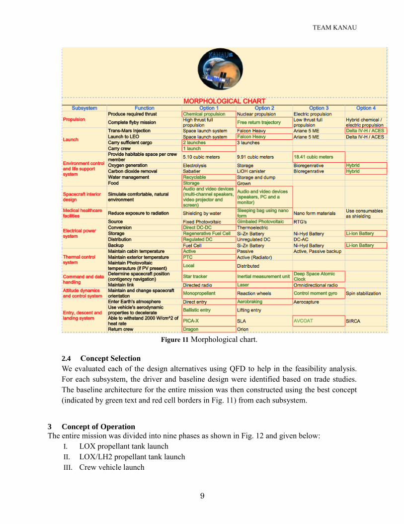
Figure 11 Morphological chart.
2.4 Concept Selection
We evaluated each of the design alternatives using QFD to help in the feasibility analysis.
For each subsystem, the driver and baseline design were identified based on trade studies.
The baseline architecture for the entire mission was then constructed using the best concept
(indicated by green text and red cell borders in Fig. 11) from each subsystem.
3 Concept of Operation
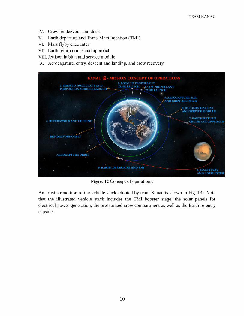
The entire mission was divided into nine phases as shown in Fig. 12 and given below:
I. LOX propellant tank launch
II. LOX/LH2 propellant tank launch
III. Crew vehicle launch
TEAM KANAU
10
IV. Crew rendezvous and dock
V. Earth departure and Trans-Mars Injection (TMI)
VI. Mars flyby encounter
VII. Earth return cruise and approach
VIII. Jettison habitat and service module
IX. Aerocapature, entry, descent and landing, and crew recovery
Figure 12 Concept of operations.
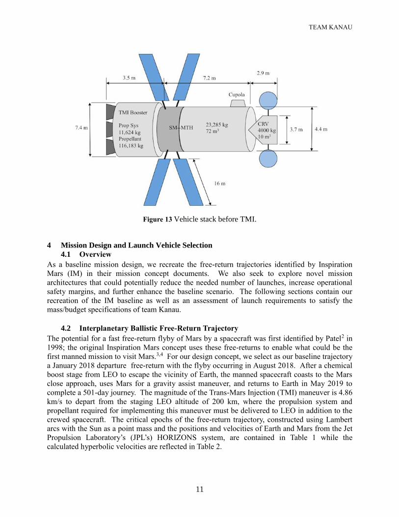
An artist’s rendition of the vehicle stack adopted by team Kanau is shown in Fig. 13. Note
that the illustrated vehicle stack includes the TMI booster stage, the solar panels for
electrical power generation, the pressurized crew compartment as well as the Earth re-entry
capsule.
TEAM KANAU
11
Figure 13 Vehicle stack before TMI.
4 Mission Design and Launch Vehicle Selection
4.1 Overview
As a baseline mission design, we recreate the free-return trajectories identified by Inspiration
Mars (IM) in their mission concept documents. We also seek to explore novel mission
architectures that could potentially reduce the needed number of launches, increase operational
safety margins, and further enhance the baseline scenario. The following sections contain our
recreation of the IM baseline as well as an assessment of launch requirements to satisfy the
mass/budget specifications of team Kanau.
4.2 Interplanetary Ballistic Free-Return Trajectory
The potential for a fast free-return flyby of Mars by a spacecraft was first identified by Patel2 in
1998; the original Inspiration Mars concept uses these free-returns to enable what could be the
first manned mission to visit Mars.3,4 For our design concept, we select as our baseline trajectory
a January 2018 departure free-return with the flyby occurring in August 2018. After a chemical
boost stage from LEO to escape the vicinity of Earth, the manned spacecraft coasts to the Mars
close approach, uses Mars for a gravity assist maneuver, and returns to Earth in May 2019 to
complete a 501-day journey. The magnitude of the Trans-Mars Injection (TMI) maneuver is 4.86
km/s to depart from the staging LEO altitude of 200 km, where the propulsion system and
propellant required for implementing this maneuver must be delivered to LEO in addition to the
crewed spacecraft. The critical epochs of the free-return trajectory, constructed using Lambert
arcs with the Sun as a point mass and the positions and velocities of Earth and Mars from the Jet
Propulsion Laboratory’s (JPL’s) HORIZONS system, are contained in Table 1 while the
calculated hyperbolic velocities are reflected in Table 2.
TEAM KANAU
12
Table 1 Critical epochs of the Earth-Mars-Earth free-return trajectory. Leg DEPART ARRIVE Flight Time (Days)
1 Earth
2018 January 04
07:10:33.6 UT
Mars
2018 August 20
07:49:43.7 UT
228.0271999998950
2 Mars 2018 August 20
07:49:43.7 UT Earth
2019 May 20
20:57:41.8 UT 273.5471999999136
Total Duration 501.5743999998086
Table 2 Velocities and periapse altitudes of the departure, fly-by, and return hyperbolic
trajectories.
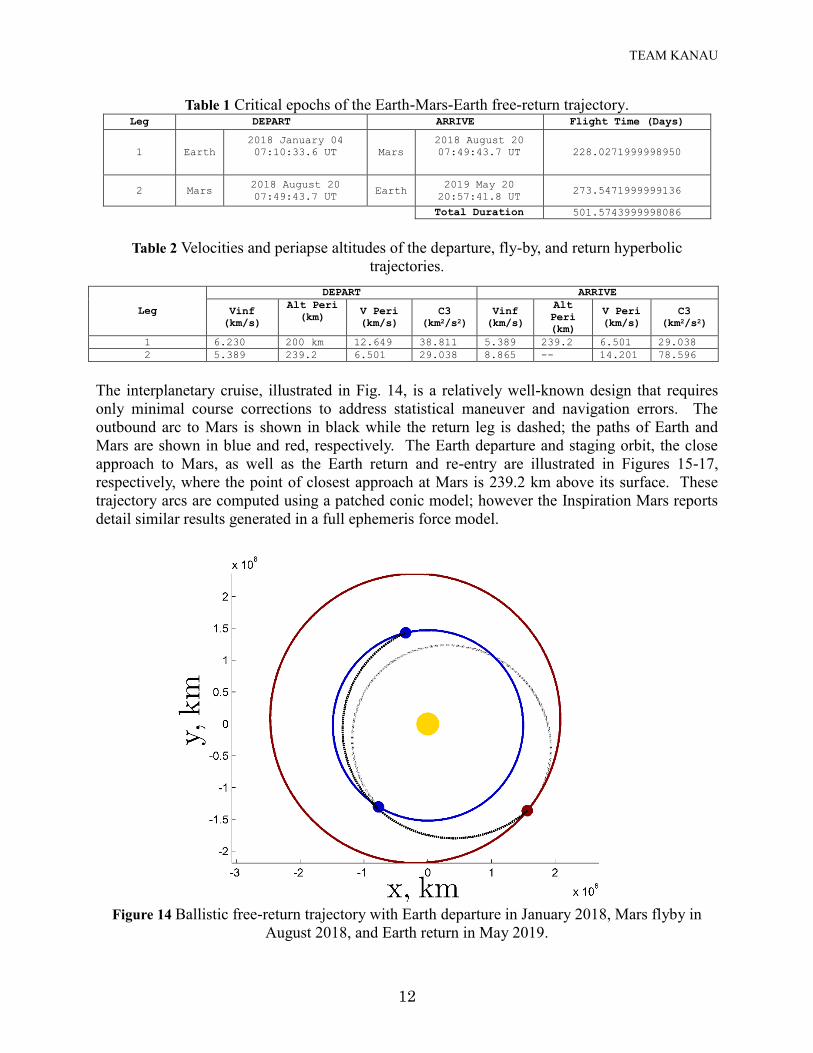
The interplanetary cruise, illustrated in Fig. 14, is a relatively well-known design that requires
only minimal course corrections to address statistical maneuver and navigation errors. The
outbound arc to Mars is shown in black while the return leg is dashed; the paths of Earth and
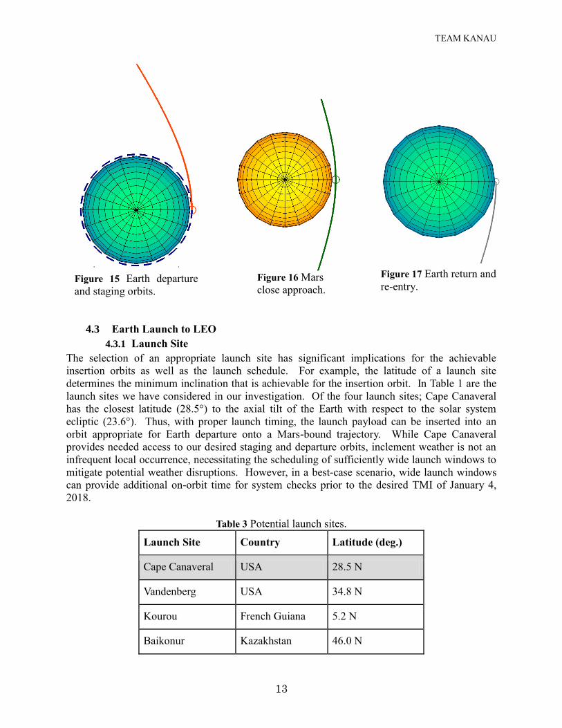
Mars are shown in blue and red, respectively. The Earth departure and staging orbit, the close
approach to Mars, as well as the Earth return and re-entry are illustrated in Figures 15-17,
respectively, where the point of closest approach at Mars is 239.2 km above its surface. These
trajectory arcs are computed using a patched conic model; however the Inspiration Mars reports
detail similar results generated in a full ephemeris force model.
Figure 14 Ballistic free-return trajectory with Earth departure in January 2018, Mars flyby in
August 2018, and Earth return in May 2019.
Leg
DEPART ARRIVE
Vinf
(km/s)
Alt Peri
(km) V Peri
(km/s)
C3
(km2/s2)
Vinf
(km/s)
Alt
Peri
(km)
V Peri
(km/s)
C3
(km2/s2)
1 6.230 200 km 12.649 38.811 5.389 239.2 6.501 29.038
2 5.389 239.2 6.501 29.038 8.865 -- 14.201 78.596
TEAM KANAU
13
4.3 Earth Launch to LEO
4.3.1 Launch Site
The selection of an appropriate launch site has significant implications for the achievable
insertion orbits as well as the launch schedule. For example, the latitude of a launch site
determines the minimum inclination that is achievable for the insertion orbit. In Table 1 are the
launch sites we have considered in our investigation. Of the four launch sites; Cape Canaveral
has the closest latitude (28.5°) to the axial tilt of the Earth with respect to the solar system
ecliptic (23.6°). Thus, with proper launch timing, the launch payload can be inserted into an
orbit appropriate for Earth departure onto a Mars-bound trajectory. While Cape Canaveral
provides needed access to our desired staging and departure orbits, inclement weather is not an
infrequent local occurrence, necessitating the scheduling of sufficiently wide launch windows to
mitigate potential weather disruptions. However, in a best-case scenario, wide launch windows
can provide additional on-orbit time for system checks prior to the desired TMI of January 4,
2018.
Table 3 Potential launch sites.
Launch Site Country Latitude (deg.)
Cape Canaveral USA 28.5 N
Vandenberg USA 34.8 N
Kourou French Guiana 5.2 N
Baikonur Kazakhstan 46.0 N
Figure 15 Earth departure
and staging orbits.
Figure 16 Mars
close approach.
Figure 17 Earth return and
re-entry.
TEAM KANAU
14
4.3.2 Launch Mass to LEO
The total mass of the spacecraft after TMI, that is the mass of the crew, capsule, and
consumables, drives the sizing of the required propellant mass and associated propulsion system.
We size the propulsion system in a three-step process:
1. Derive, via the Ideal Rocket Equation ∆𝑉
𝑣𝑒= ln
𝑚𝑠𝑐+𝑚𝑝𝑖
𝑚𝑠𝑐, the required propellant mass (mpi)
to insert the spacecraft mass (msc) onto the Earth departure trajectory.
2. Size the propulsion system by applying a 15% fraction to the currently computed
propellant mass, 𝑚𝑝𝑠 = 0.15𝑚𝑝𝑖.
3. Find the true propellant mass, 𝑚𝑝, from the Ideal Rocket Equation using the combined
mass of the spacecraft and the propulsion system, ∆𝑉
𝑣𝑒= ln
𝑚𝑠𝑐+𝑚𝑝𝑠+𝑚𝑝
𝑚𝑠𝑐+𝑚𝑝𝑠.
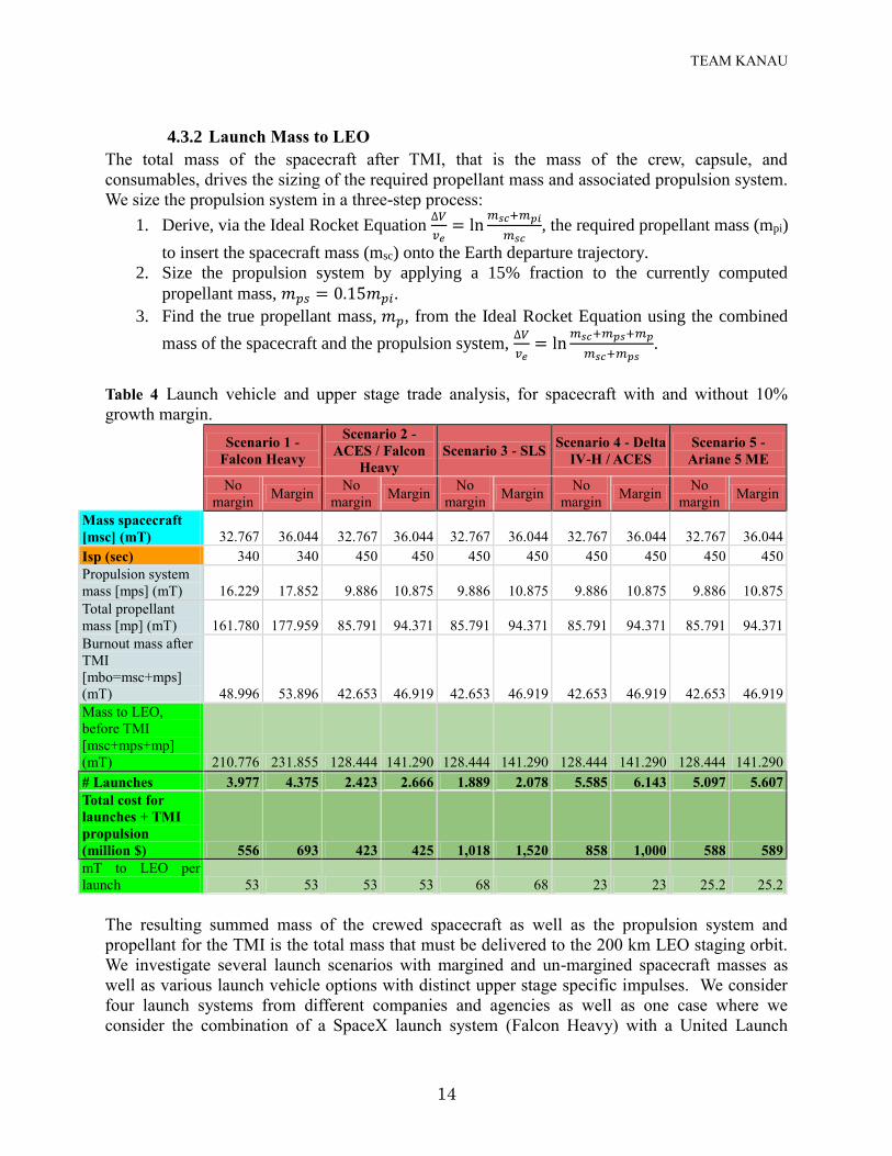
Table 4 Launch vehicle and upper stage trade analysis, for spacecraft with and without 10%
growth margin.
Scenario 1 -
Falcon Heavy
Scenario 2 -
ACES / Falcon
Heavy
Scenario 3 - SLS Scenario 4 - Delta
IV-H / ACES
Scenario 5 -
Ariane 5 ME
No
margin Margin
No
margin Margin
No
margin Margin
No
margin Margin
No
margin Margin
Mass spacecraft
[msc] (mT) 32.767 36.044 32.767 36.044 32.767 36.044 32.767 36.044 32.767 36.044
Isp (sec) 340 340 450 450 450 450 450 450 450 450
Propulsion system
mass [mps] (mT) 16.229 17.852 9.886 10.875 9.886 10.875 9.886 10.875 9.886 10.875
Total propellant
mass [mp] (mT) 161.780 177.959 85.791 94.371 85.791 94.371 85.791 94.371 85.791 94.371
Burnout mass after
TMI
[mbo=msc+mps]
(mT) 48.996 53.896 42.653 46.919 42.653 46.919 42.653 46.919 42.653 46.919
Mass to LEO,
before TMI
[msc+mps+mp]
(mT) 210.776 231.855 128.444 141.290 128.444 141.290 128.444 141.290 128.444 141.290
# Launches 3.977 4.375 2.423 2.666 1.889 2.078 5.585 6.143 5.097 5.607
Total cost for
launches + TMI
propulsion
(million $) 556 693 423 425 1,018 1,520 858 1,000 588 589
mT to LEO per
launch 53 53 53 53 68 68 23 23 25.2 25.2
The resulting summed mass of the crewed spacecraft as well as the propulsion system and
propellant for the TMI is the total mass that must be delivered to the 200 km LEO staging orbit.
We investigate several launch scenarios with margined and un-margined spacecraft masses as
well as various launch vehicle options with distinct upper stage specific impulses. We consider
four launch systems from different companies and agencies as well as one case where we
consider the combination of a SpaceX launch system (Falcon Heavy) with a United Launch
TEAM KANAU
15
Alliance (ULA) upper stage (ACES). Note that of the five launch vehicles considered, all
require further technology development and demonstration flights prior to the launch date of
January 2018. The total cost for each scenario is determined by adding the stated launch cost to
LEO from the launch service providers to an estimated cost of the TMI propulsion based upon
the dollar per mass ratio for the respective launch system upper stage.
4.3.3 Selection of Launch Architecture and Timeline
Of the launch scenarios considered, we select as our primary option the Falcon Heavy launch to
LEO with the ACES upper stage. We choose this scenario based upon expected launch cost as
well as estimated technology readiness level; while this configuration will require collaboration
between competing launch service providers, the years leading up to the 2018 mission
opportunity can be used to finalize technical and organizational details. The Falcon Heavy is
expected to first launch in 2014, leaving several years to the human rating of the system, while
the ACES system is built upon proven ULA hardware, whereas competing options such as SLS
Block I (Block II will not be developed in time for 2018 launch opportunity) and Ariane 5 are not
expected to have demonstration flights until 2017 at the earliest, leaving a slim margin for further
testing of the system. The Falcon Heavy by itself is another cost effective option, however it
requires significantly more launches and therefore adds to the complexity of the mission. While
the Delta IV-H has a proven record of successful launches and the ACES configuration is
designed to replace the current upper stages for this launch vehicle, the Delta IV-H is also more
expensive than the Falcon Heavy. While we select the Falcon Heavy / ACES configuration as our
primary launch scenario, we retain the other competing options as viable contingency options.
For both the margined and un-margined spacecraft, our baseline scenario requires a total of 3
launches, however only the final launch carrying the crew must occur within a short time frame
before the nominal TMI. On the other hand, the cryogenic nature of the LOX / LH2 propellant
that the ACES stage uses means that boil-off is a concern while the propellant is in the staging
orbit.5 Therefore, even though on-orbit cryogenic storage must be used for the fuel and oxidizer,
launches of the storage tanks should not occur too early before the launch of the crewed capsule.
Since boil-off of liquid hydrogen occurs at a faster rate than LOX, the LH2 tanks must be placed
on the second propellant launch. We therefore propose the launch timeline in Table 5, where
weather events at the launch site that could unduly affect the mission timeline are also
accommodated for by scheduling a two-week window between each propellant launch. A shorter
launch window is used for the crew in order to reduce the crew time in the staging orbit prior to
TMI. Note that the last launch opportunity for the crewed launch is constrained to terminate one
day prior to the nominal TMI so that on-orbit systems checks may be performed prior to TMI.
Table 5 Launch timeline.
Launch Payload to LEO Window
1 LOX propellant tank Nov. 26th - Dec. 10th, 2017
2 LOX / LH2 propellant tanks Dec. 10th – Dec. 24th, 2017
3 Crewed spacecraft + propulsion module Dec. 24th, 2017 – Jan. 3rd, 2018
TEAM KANAU
16
5 Aerocapture
To reduce the re-entry velocity the options of aerobraking and aerocapture were investigated.
Table 1 in appendix A shows the comparison between both these aero-assist methods. Although
aerobraking has been performed four times6 in the past, it is not suitable for human missions and
hence aerocapture was selected to reduce the re-entry velocity.
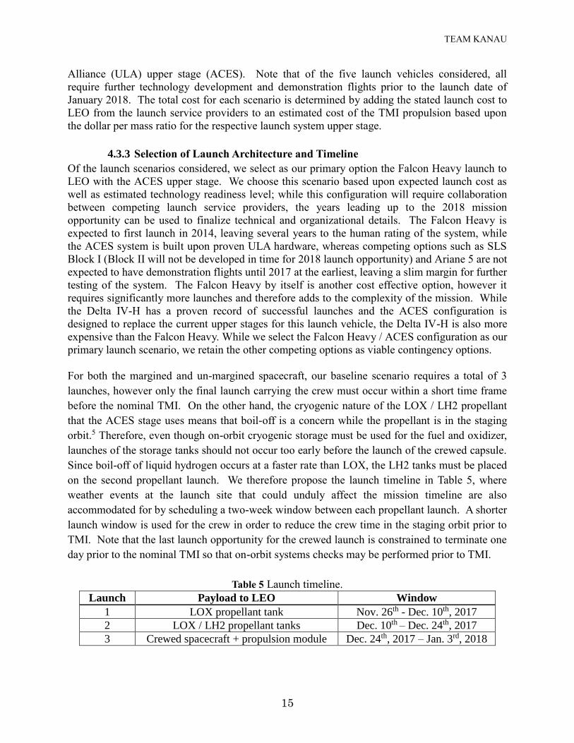
The General Mission Analysis Tool7 (GMAT) developed by NASA Goddard was used to perform
aerocapture analysis for this mission. The idea of aerocapture is to utilize Earth’s atmosphere to
provide an effective reduction in velocity such that the spacecraft shifts from a high-energy
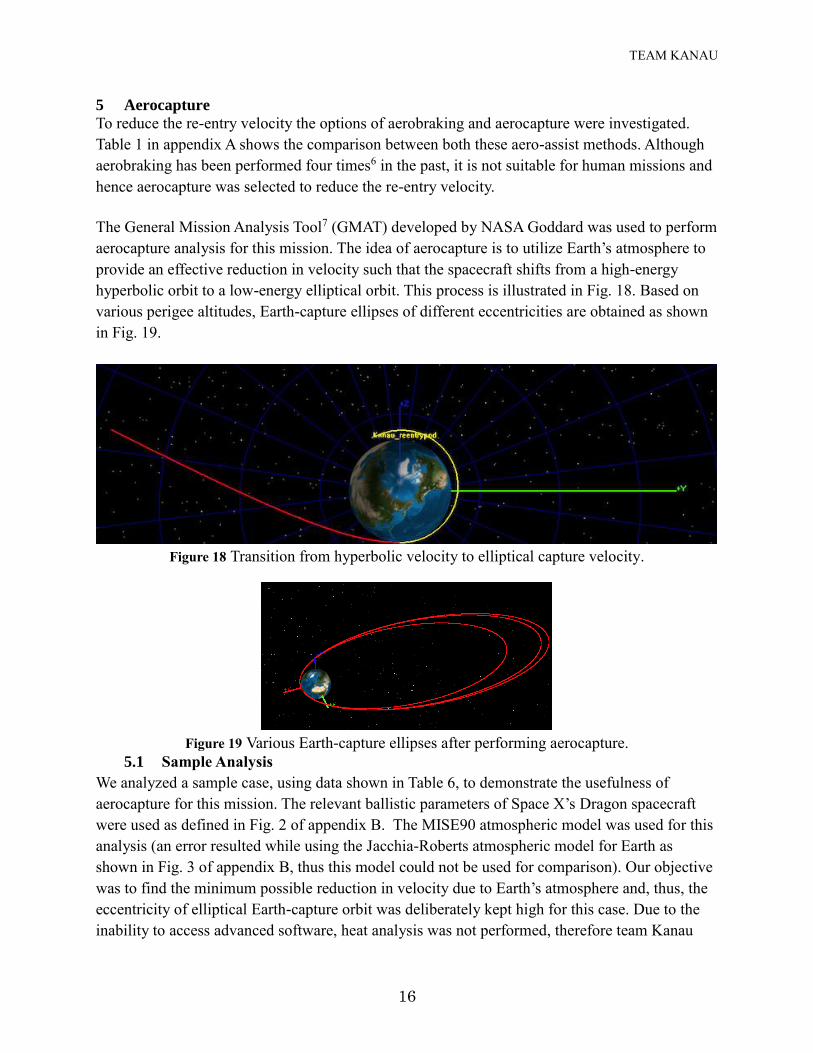
hyperbolic orbit to a low-energy elliptical orbit. This process is illustrated in Fig. 18. Based on
various perigee altitudes, Earth-capture ellipses of different eccentricities are obtained as shown
in Fig. 19.
Figure 18 Transition from hyperbolic velocity to elliptical capture velocity.
Figure 19 Various Earth-capture ellipses after performing aerocapture.
5.1 Sample Analysis
We analyzed a sample case, using data shown in Table 6, to demonstrate the usefulness of
aerocapture for this mission. The relevant ballistic parameters of Space X’s Dragon spacecraft
were used as defined in Fig. 2 of appendix B. The MISE90 atmospheric model was used for this
analysis (an error resulted while using the Jacchia-Roberts atmospheric model for Earth as
shown in Fig. 3 of appendix B, thus this model could not be used for comparison). Our objective
was to find the minimum possible reduction in velocity due to Earth’s atmosphere and, thus, the
eccentricity of elliptical Earth-capture orbit was deliberately kept high for this case. Due to the
inability to access advanced software, heat analysis was not performed, therefore team Kanau
TEAM KANAU
17
suggests further heat analysis for determining both heat rate and heat load on the re-entry
vehicle. Assuming a corridor width requirement of 0.7 degrees, vehicles with an L/D of 0.4-0.5
are found to be satisfactory for arrival speeds up to 14.5 km/s and g-loads lesser than 5 gs.8 The
current L/D ratio for Dragon is 0.189 , so we suggest that improvements be made to the current
technology to increase this value to 0.4 for better results using aerocapture.
Table 6 Aerocapture sample analysis data.
Parameter Value
Altitude at maximum velocity (km) 123.9468
Maximum velocity during re-entry (km/s) 14.1326
Perigee altitude (km) 56.3637
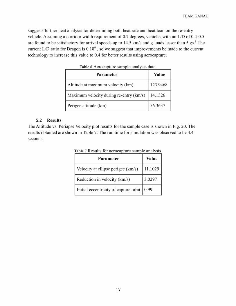
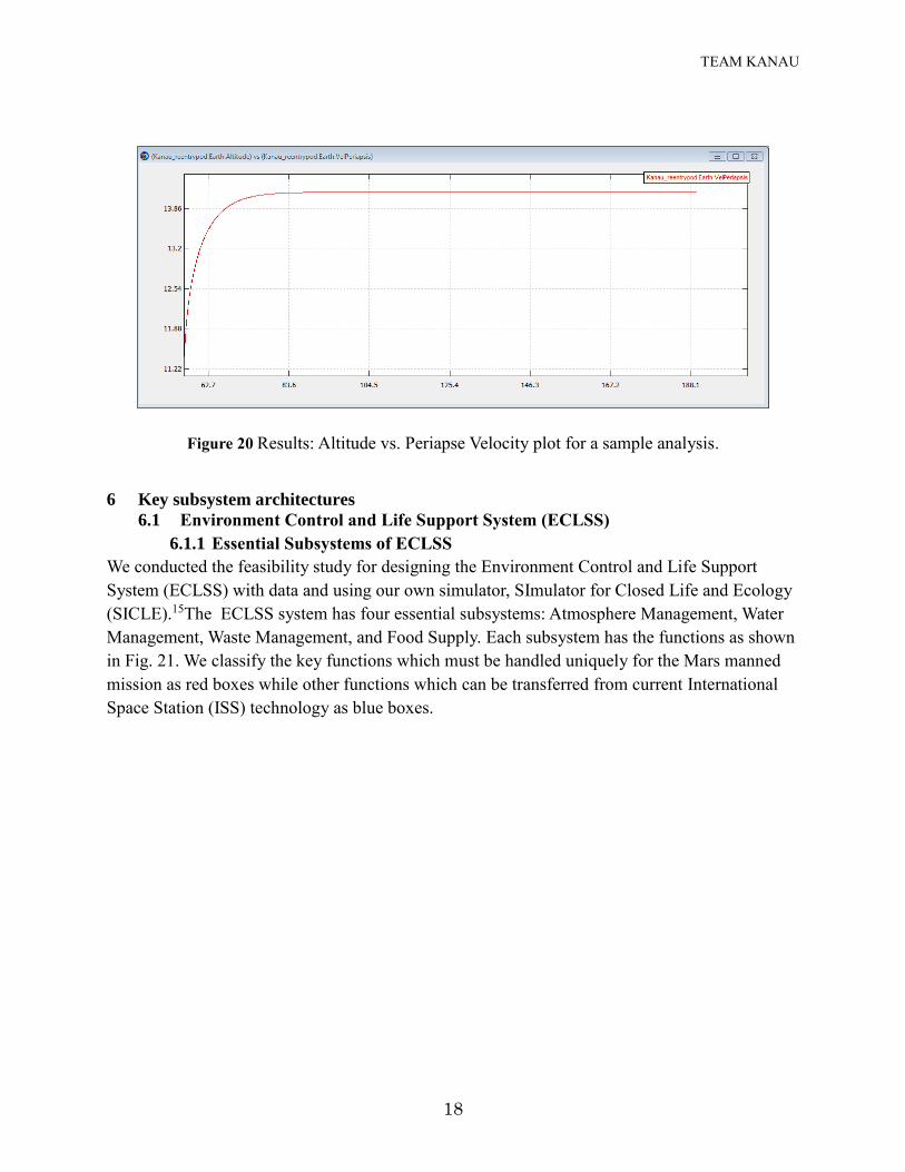
5.2 Results
The Altitude vs. Periapse Velocity plot results for the sample case is shown in Fig. 20. The
results obtained are shown in Table 7. The run time for simulation was observed to be 4.4
seconds.
Table 7 Results for aerocapture sample analysis.
Parameter Value
Velocity at ellipse perigee (km/s) 11.1029
Reduction in velocity (km/s) 3.0297
Initial eccentricity of capture orbit 0.99
TEAM KANAU
18
Figure 20 Results: Altitude vs. Periapse Velocity plot for a sample analysis.
6 Key subsystem architectures
6.1 Environment Control and Life Support System (ECLSS)
6.1.1 Essential Subsystems of ECLSS
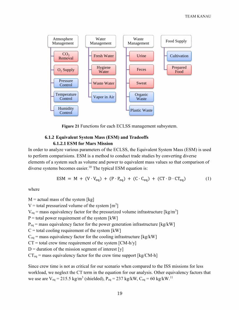
We conducted the feasibility study for designing the Environment Control and Life Support
System (ECLSS) with data and using our own simulator, SImulator for Closed Life and Ecology
(SICLE).15The ECLSS system has four essential subsystems: Atmosphere Management, Water
Management, Waste Management, and Food Supply. Each subsystem has the functions as shown
in Fig. 21. We classify the key functions which must be handled uniquely for the Mars manned
mission as red boxes while other functions which can be transferred from current International
Space Station (ISS) technology as blue boxes.
TEAM KANAU
19
Figure 21 Functions for each ECLSS management subsystem.
6.1.2 Equivalent System Mass (ESM) and Tradeoffs
6.1.2.1 ESM for Mars Mission
In order to analyze various parameters of the ECLSS, the Equivalent System Mass (ESM) is used
to perform comparisions. ESM is a method to conduct trade studies by converting diverse
elements of a system such as volume and power to equivalent mass values so that comparison of
diverse systems becomes easier.10 The typical ESM equation is:
ESM = M + (V ⋅ Veq) + (P ⋅ Peq) + (C ⋅ Ceq) + (CT ⋅ D ⋅ CTeq) (1)
where
M = actual mass of the system [kg]
V = total pressurized volume of the system [m3]
Veq = mass equivalency factor for the pressurized volume infrastructure [kg/m3]
P = total power requirement of the system [kW]
Peq = mass equivalency factor for the power generation infrastructure [kg/kW]
C = total cooling requirement of the system [kW]
Ceq = mass equivalency factor for the cooling infrastructure [kg/kW]
CT = total crew time requirement of the system [CM-h/y]
D = duration of the mission segment of interest [y]
CTeq = mass equivalency factor for the crew time support [kg/CM-h]
Since crew time is not as critical for our scenario when compared to the ISS missions for less
workload, we neglect the CT term in the equation for our analysis. Other equivalency factors that
we use are Veq = 215.5 kg/m3 (shielded), Peq = 237 kg/kW, Ceq = 60 kg/kW.11
Atmosphere Management
CO2
Removal
O2 Supply
Pressure Control
Temperature Control
Humidity Control
Water Management
Fresh Water
Hygiene Water
Waste Water
Vapor in Air
Waste Management
Urine
Feces
Sweat
Organic Waste
Plastic Waste
Food Supply
Cultivation
Prepared Food
TEAM KANAU
20
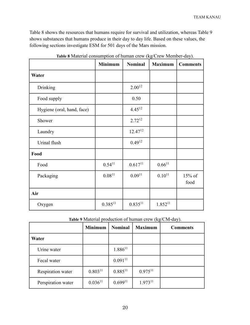
Table 8 shows the resources that humans require for survival and utilization, whereas Table 9
shows substances that humans produce in their day to day life. Based on these values, the
following sections investigate ESM for 501 days of the Mars mission.
Table 8 Material consumption of human crew (kg/Crew Member-day).
Table 9 Material production of human crew (kg/CM-day).
Minimum Nominal Maximum Comments
Water
Urine water 1.88611
Fecal water 0.09111
Respiration water 0.80311 0.88511 0.97511
Perspiration water 0.03611 0.69911 1.97311
Minimum Nominal Maximum Comments
Water
Drinking 2.0012
Food supply 0.50
Hygiene (oral, hand, face) 4.4512
Shower 2.7212
Laundry 12.4712
Urinal flush 0.4912
Food
Food 0.5411 0.61711 0.6611
Packaging 0.0811 0.0911 0.1011 15% of
food
Air
Oxygen 0.38511 0.83511 1.85211
TEAM KANAU
21
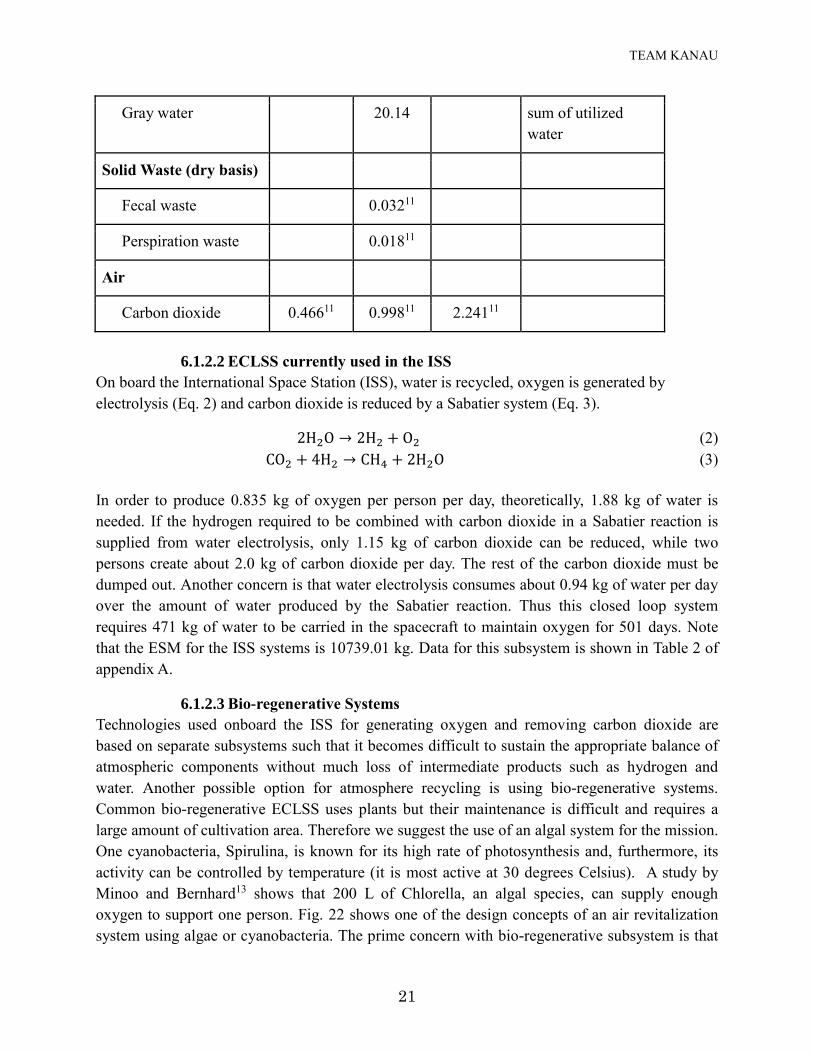
Gray water 20.14 sum of utilized
water
Solid Waste (dry basis)
Fecal waste 0.03211
Perspiration waste 0.01811
Air
Carbon dioxide 0.46611 0.99811 2.24111
6.1.2.2 ECLSS currently used in the ISS
On board the International Space Station (ISS), water is recycled, oxygen is generated by
electrolysis (Eq. 2) and carbon dioxide is reduced by a Sabatier system (Eq. 3).
2H2O → 2H2 + O2 (2)
CO2 + 4H2 → CH4 + 2H2O (3)
In order to produce 0.835 kg of oxygen per person per day, theoretically, 1.88 kg of water is
needed. If the hydrogen required to be combined with carbon dioxide in a Sabatier reaction is
supplied from water electrolysis, only 1.15 kg of carbon dioxide can be reduced, while two
persons create about 2.0 kg of carbon dioxide per day. The rest of the carbon dioxide must be
dumped out. Another concern is that water electrolysis consumes about 0.94 kg of water per day
over the amount of water produced by the Sabatier reaction. Thus this closed loop system
requires 471 kg of water to be carried in the spacecraft to maintain oxygen for 501 days. Note
that the ESM for the ISS systems is 10739.01 kg. Data for this subsystem is shown in Table 2 of
appendix A.
6.1.2.3 Bio-regenerative Systems
Technologies used onboard the ISS for generating oxygen and removing carbon dioxide are
based on separate subsystems such that it becomes difficult to sustain the appropriate balance of
atmospheric components without much loss of intermediate products such as hydrogen and
water. Another possible option for atmosphere recycling is using bio-regenerative systems.
Common bio-regenerative ECLSS uses plants but their maintenance is difficult and requires a
large amount of cultivation area. Therefore we suggest the use of an algal system for the mission.
One cyanobacteria, Spirulina, is known for its high rate of photosynthesis and, furthermore, its
activity can be controlled by temperature (it is most active at 30 degrees Celsius). A study by
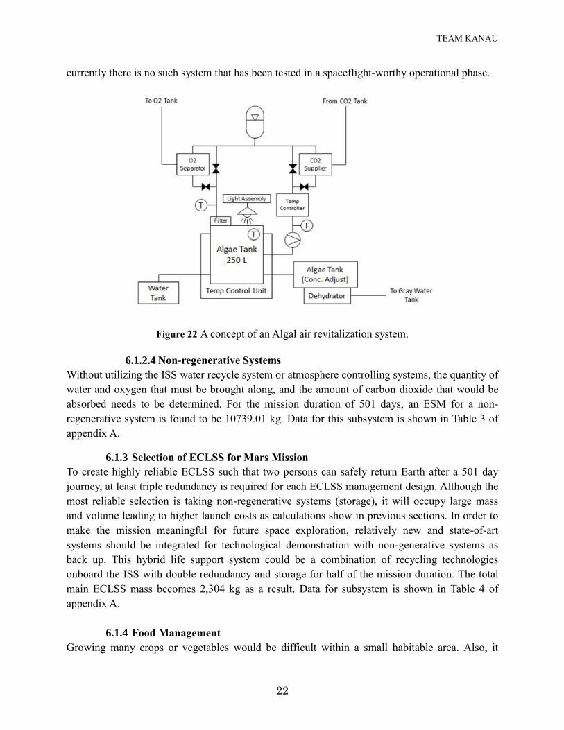
Minoo and Bernhard13 shows that 200 L of Chlorella, an algal species, can supply enough
oxygen to support one person. Fig. 22 shows one of the design concepts of an air revitalization
system using algae or cyanobacteria. The prime concern with bio-regenerative subsystem is that
TEAM KANAU
22
currently there is no such system that has been tested in a spaceflight-worthy operational phase.
Figure 22 A concept of an Algal air revitalization system.
6.1.2.4 Non-regenerative Systems
Without utilizing the ISS water recycle system or atmosphere controlling systems, the quantity of
water and oxygen that must be brought along, and the amount of carbon dioxide that would be
absorbed needs to be determined. For the mission duration of 501 days, an ESM for a non-
regenerative system is found to be 10739.01 kg. Data for this subsystem is shown in Table 3 of
appendix A.
6.1.3 Selection of ECLSS for Mars Mission
To create highly reliable ECLSS such that two persons can safely return Earth after a 501 day
journey, at least triple redundancy is required for each ECLSS management design. Although the
most reliable selection is taking non-regenerative systems (storage), it will occupy large mass
and volume leading to higher launch costs as calculations show in previous sections. In order to
make the mission meaningful for future space exploration, relatively new and state-of-art
systems should be integrated for technological demonstration with non-generative systems as
back up. This hybrid life support system could be a combination of recycling technologies
onboard the ISS with double redundancy and storage for half of the mission duration. The total
main ECLSS mass becomes 2,304 kg as a result. Data for subsystem is shown in Table 4 of
appendix A.
6.1.4 Food Management
Growing many crops or vegetables would be difficult within a small habitable area. Also, it
TEAM KANAU
23
would be an inefficient use of space for a crew size of two for the mission duration, so food
supplies should be precooked foods such that it is ready to eat by just reheating or adding water.
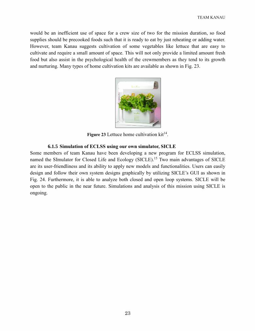
However, team Kanau suggests cultivation of some vegetables like lettuce that are easy to
cultivate and require a small amount of space. This will not only provide a limited amount fresh
food but also assist in the psychological health of the crewmembers as they tend to its growth
and nurturing. Many types of home cultivation kits are available as shown in Fig. 23.
Figure 23 Lettuce home cultivation kit14.
6.1.5 Simulation of ECLSS using our own simulator, SICLE
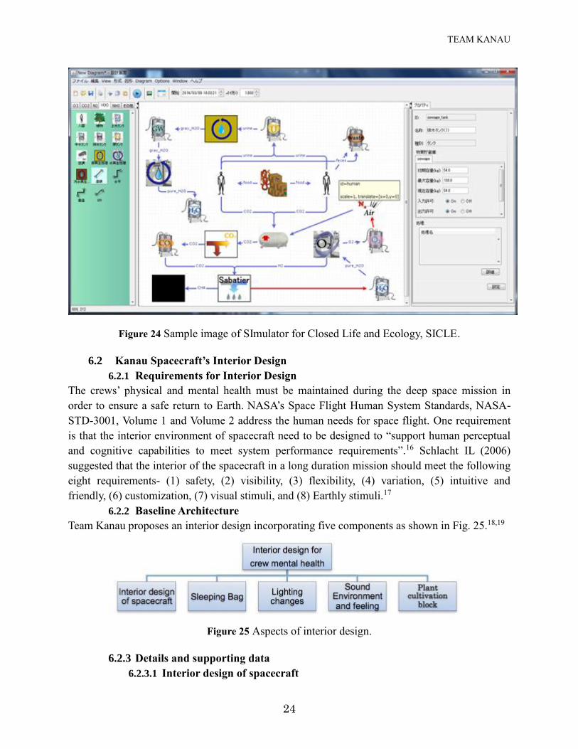
Some members of team Kanau have been developing a new program for ECLSS simulation,
named the SImulator for Closed Life and Ecology (SICLE).15 Two main advantages of SICLE
are its user-friendliness and its ability to apply new models and functionalities. Users can easily
design and follow their own system designs graphically by utilizing SICLE’s GUI as shown in
Fig. 24. Furthermore, it is able to analyze both closed and open loop systems. SICLE will be
open to the public in the near future. Simulations and analysis of this mission using SICLE is
ongoing.
TEAM KANAU
24
Figure 24 Sample image of SImulator for Closed Life and Ecology, SICLE.
6.2 Kanau Spacecraft’s Interior Design
6.2.1 Requirements for Interior Design
The crews’ physical and mental health must be maintained during the deep space mission in
order to ensure a safe return to Earth. NASA’s Space Flight Human System Standards, NASA-
STD-3001, Volume 1 and Volume 2 address the human needs for space flight. One requirement
is that the interior environment of spacecraft need to be designed to “support human perceptual
and cognitive capabilities to meet system performance requirements”.16 Schlacht IL (2006)
suggested that the interior of the spacecraft in a long duration mission should meet the following
eight requirements- (1) safety, (2) visibility, (3) flexibility, (4) variation, (5) intuitive and
friendly, (6) customization, (7) visual stimuli, and (8) Earthly stimuli.17
6.2.2 Baseline Architecture
Team Kanau proposes an interior design incorporating five components as shown in Fig. 25.18,19
Figure 25 Aspects of interior design.
6.2.3 Details and supporting data
6.2.3.1 Interior design of spacecraft
TEAM KANAU
25
All potential dangers should be removed to ensure (1) safety during the mission, (2) visibility
when crew participates in some activities, (3) flexibility to adapt to various situations, (4)
variability because monotony of visual stimuli leads to strong discomfort, which is certified by
past space missions like Skylab Space Station 4,20 and (5) intuitive and friendly design.
6.2.3.2 Sleeping bag
Customization of spacecraft is needed because interviews of astronauts suggest privacy is the
most important factor for crew.21 The crewmembers of Inspiration Mars mission will be a long-
time married couple and hence a sleeping bag for the two people should suffice. Physical
intimacy is one important factor to maintain the healthy relationship of a married couple.
Therefore, such a sleeping bag and placement of any cameras will be important considerations.
Furthermore, the use of nano materials could reduce radiation exposure during sleeping, thus the
sleeping area could also be a shelter in the case of a high radiation event.18
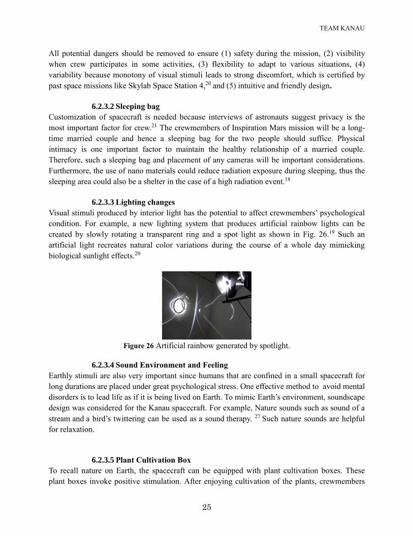
6.2.3.3 Lighting changes
Visual stimuli produced by interior light has the potential to affect crewmembers’ psychological
condition. For example, a new lighting system that produces artificial rainbow lights can be
created by slowly rotating a transparent ring and a spot light as shown in Fig. 26.19 Such an
artificial light recreates natural color variations during the course of a whole day mimicking
biological sunlight effects.20
Figure 26 Artificial rainbow generated by spotlight.
6.2.3.4 Sound Environment and Feeling
Earthly stimuli are also very important since humans that are confined in a small spacecraft for
long durations are placed under great psychological stress. One effective method to avoid mental
disorders is to lead life as if it is being lived on Earth. To mimic Earth’s environment, soundscape
design was considered for the Kanau spacecraft. For example, Nature sounds such as sound of a
stream and a bird’s twittering can be used as a sound therapy. 27 Such nature sounds are helpful
for relaxation.
6.2.3.5 Plant Cultivation Box
To recall nature on Earth, the spacecraft can be equipped with plant cultivation boxes. These
plant boxes invoke positive stimulation. After enjoying cultivation of the plants, crewmembers
TEAM KANAU
26
can eat them for additional variety in their diet. Cultivating plants in a spacecraft is a difficult
task but imitations of wood, grain or artificial flowers can also help in mental relaxation of
crewmembers.19
6.3 Facilities for crew physical health
6.3.1 Requirements for crew physical health
This system needs to provide measures to meet crew bone, muscle, sensory-motor, and
cardiovascular standards defined in NASA-STD-3001, Volume 1. Measures shall maintain in-
flight skeletal muscle strength at or above 80 percent of baseline values and bone mass consistent
with requirements for a safe return to Earth’s gravity.22 The exercise and muscle data gathered
from nine crewmembers while on the ISS for 6 months clearly support the notion that changes to
the exercise prescription are necessary to protect skeletal muscle for long-duration space
missions.23
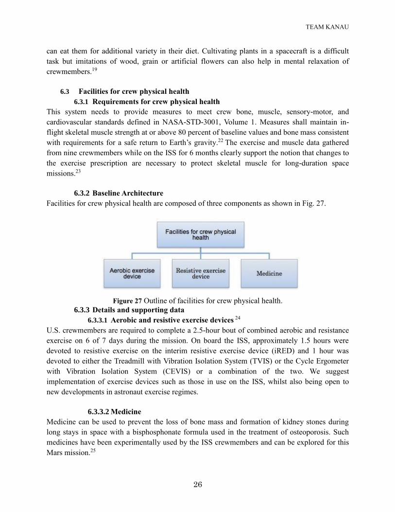
6.3.2 Baseline Architecture
Facilities for crew physical health are composed of three components as shown in Fig. 27.
Figure 27 Outline of facilities for crew physical health.
6.3.3 Details and supporting data
6.3.3.1 Aerobic and resistive exercise devices 24
U.S. crewmembers are required to complete a 2.5-hour bout of combined aerobic and resistance
exercise on 6 of 7 days during the mission. On board the ISS, approximately 1.5 hours were
devoted to resistive exercise on the interim resistive exercise device (iRED) and 1 hour was
devoted to either the Treadmill with Vibration Isolation System (TVIS) or the Cycle Ergometer
with Vibration Isolation System (CEVIS) or a combination of the two. We suggest
implementation of exercise devices such as those in use on the ISS, whilst also being open to
new developments in astronaut exercise regimes.
6.3.3.2 Medicine
Medicine can be used to prevent the loss of bone mass and formation of kidney stones during
long stays in space with a bisphosphonate formula used in the treatment of osteoporosis. Such
medicines have been experimentally used by the ISS crewmembers and can be explored for this
Mars mission.25
TEAM KANAU
27
6.4 Facilities for Radiation Protection
6.4.1 Requirements for Radiation Protection
Crew occupational exposure to ionizing radiation should be managed through system design and
the application of appropriate countermeasures.26 Countermeasure for cosmic radiation is one of
the most critical issues for long duration, deep space missions. Radiation may cause cancer and
other types of tissue damage to the crew. In addition, the crew must evacuate to a shelter for
several hours to one day during the event of a solar storm.27
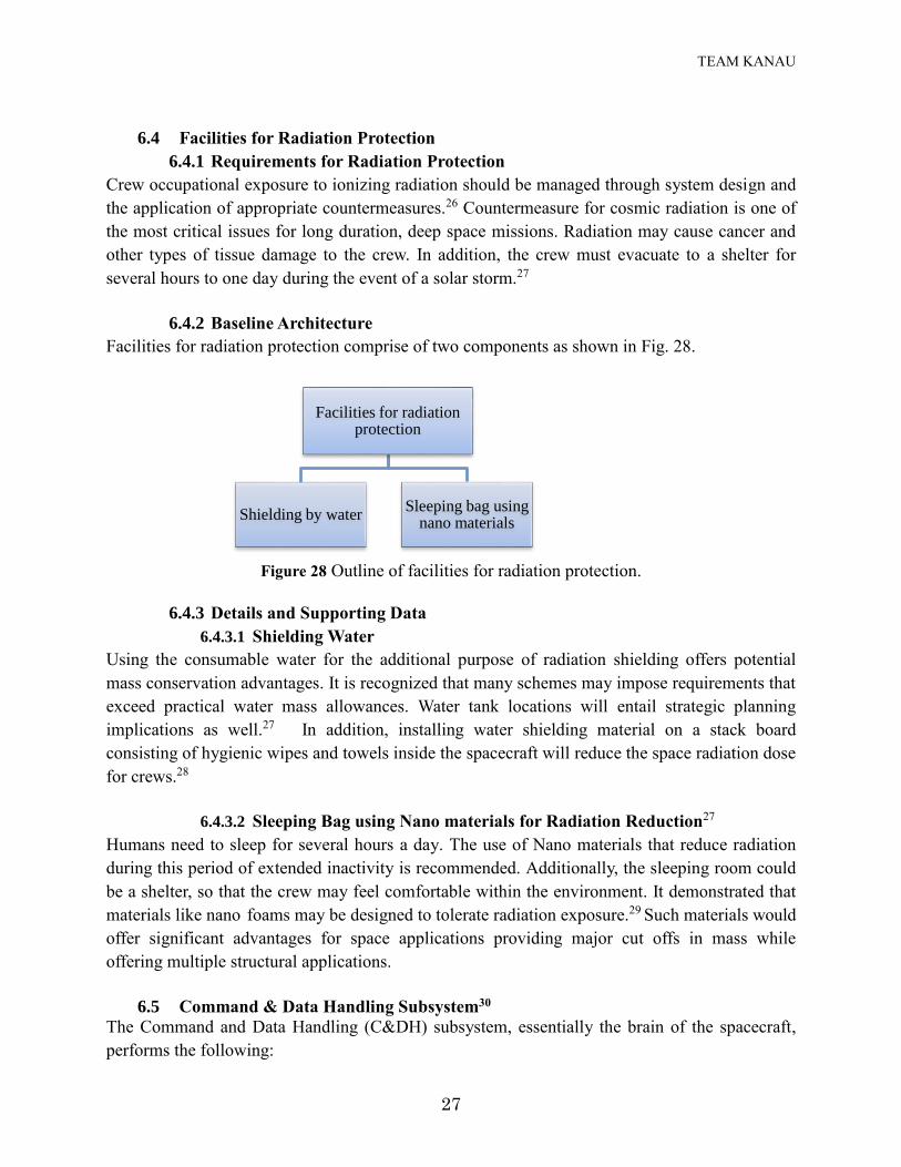
6.4.2 Baseline Architecture
Facilities for radiation protection comprise of two components as shown in Fig. 28.
Figure 28 Outline of facilities for radiation protection.
6.4.3 Details and Supporting Data
6.4.3.1 Shielding Water
Using the consumable water for the additional purpose of radiation shielding offers potential
mass conservation advantages. It is recognized that many schemes may impose requirements that
exceed practical water mass allowances. Water tank locations will entail strategic planning
implications as well.27 In addition, installing water shielding material on a stack board
consisting of hygienic wipes and towels inside the spacecraft will reduce the space radiation dose
for crews.28
6.4.3.2 Sleeping Bag using Nano materials for Radiation Reduction27
Humans need to sleep for several hours a day. The use of Nano materials that reduce radiation
during this period of extended inactivity is recommended. Additionally, the sleeping room could
be a shelter, so that the crew may feel comfortable within the environment. It demonstrated that
materials like nano foams may be designed to tolerate radiation exposure.29 Such materials would
offer significant advantages for space applications providing major cut offs in mass while
offering multiple structural applications.
6.5 Command & Data Handling Subsystem30
The Command and Data Handling (C&DH) subsystem, essentially the brain of the spacecraft,
performs the following:
Facilities for radiation protection
Shielding by waterSleeping bag using
nano materials
TEAM KANAU
28
manages all forms of data on the spacecraft
carries out commands sent from Earth
prepares data for transmission to Earth
manages collection of solar power and charging of the batteries
collects and processes information about all subsystems and payloads
keeps and distributes the spacecraft time
carries out commanded maneuvers
autonomously monitors and responds to a wide range of onboard problems that might
occur.
The key parts of this system are:
Space Flight Computer: Consists of next generation of space-qualified processors. The team
suggests use of RAD5500 PowerPC processor that is 10 times faster than RAD750
processor.31
Flight Software: The Flight Software is an integral part of the Space Flight Computer, and
includes many applications like Fault Protection running on top of an operating system.
Solid State Recorder: The primary storage for science instrument data onboard the
spacecraft. The science data is stored on this recorder until it is ready for transmission to
Earth, and then is overwritten with new science data.
6.5.1 Requirements30
Perform all functions requested of a command and control module in a complex spacecraft.
Provide continuous audio and video link with the ground station.
Provide internet-style connection.
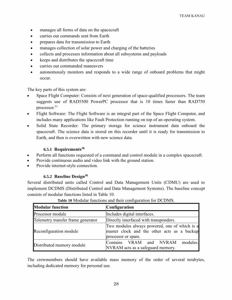
6.5.2 Baseline Design30
Several distributed units called Control and Data Management Units (CDMU) are used to
implement DCDMS (Distributed Control and Data Management Systems). The baseline concept
consists of modular functions listed in Table 10.
Table 10 Modular functions and their configuration for DCDMS.
Modular function Configuration
Processor module Includes digital interfaces.
Telemetry transfer frame generator Directly interfaced with transponders.
Reconfiguration module
Two modules always powered, one of which is a
master clock and the other acts as a backup
processor or spare.
Distributed memory module Contains VRAM and NVRAM modules.
NVRAM acts as a safeguard memory.
The crewmembers should have available mass memory of the order of several terabytes,
including dedicated memory for personal use.
TEAM KANAU
29
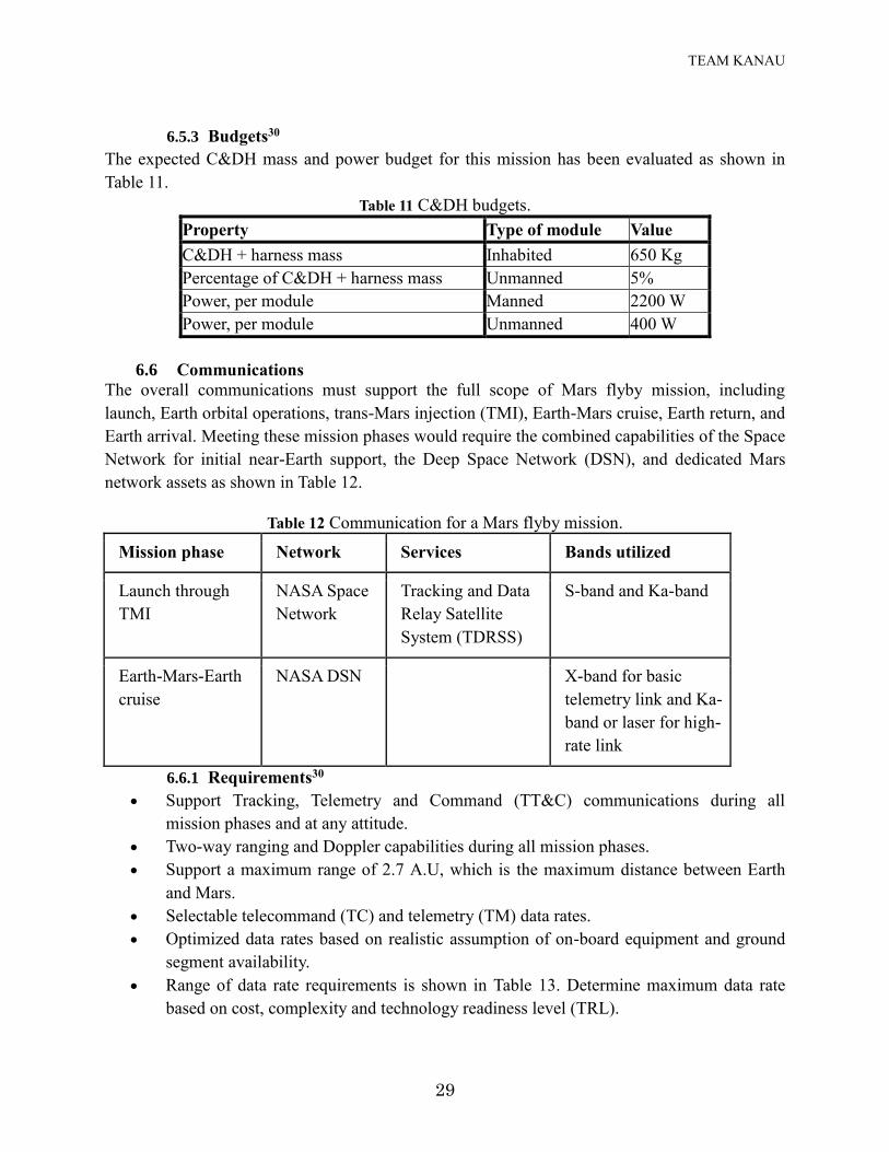
6.5.3 Budgets30
The expected C&DH mass and power budget for this mission has been evaluated as shown in
Table 11.
Table 11 C&DH budgets.
Property Type of module Value
C&DH + harness mass Inhabited 650 Kg
Percentage of C&DH + harness mass Unmanned 5%
Power, per module Manned 2200 W
Power, per module Unmanned 400 W
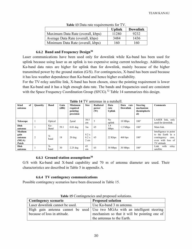
6.6 Communications
The overall communications must support the full scope of Mars flyby mission, including
launch, Earth orbital operations, trans-Mars injection (TMI), Earth-Mars cruise, Earth return, and
Earth arrival. Meeting these mission phases would require the combined capabilities of the Space
Network for initial near-Earth support, the Deep Space Network (DSN), and dedicated Mars
network assets as shown in Table 12.
Table 12 Communication for a Mars flyby mission.
Mission phase Network Services Bands utilized
Launch through
TMI
NASA Space
Network
Tracking and Data
Relay Satellite
System (TDRSS)
S-band and Ka-band
Earth-Mars-Earth
cruise
NASA DSN X-band for basic
telemetry link and Ka-
band or laser for high-
rate link
6.6.1 Requirements30
Support Tracking, Telemetry and Command (TT&C) communications during all
mission phases and at any attitude.
Two-way ranging and Doppler capabilities during all mission phases.
Support a maximum range of 2.7 A.U, which is the maximum distance between Earth
and Mars.
Selectable telecommand (TC) and telemetry (TM) data rates.
Optimized data rates based on realistic assumption of on-board equipment and ground
segment availability.
Range of data rate requirements is shown in Table 13. Determine maximum data rate
based on cost, complexity and technology readiness level (TRL).
TEAM KANAU
30
Table 13 Data rate requirements for TV.
Uplink Downlink
Maximum Data Rate (overall, kbps) 11280 9232
Average Data Rate (overall, kbps) 3484 1436
Minimum Data Rate (overall, kbps) 160 160
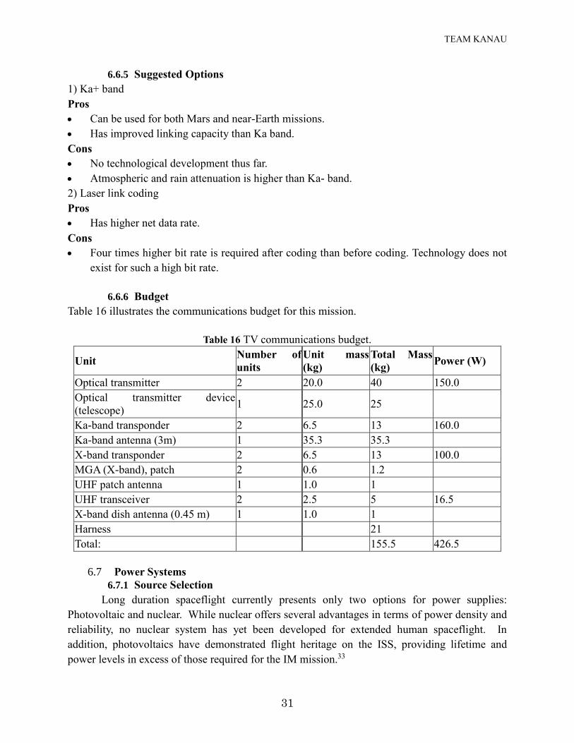
6.6.2 Band and Frequency Design30
Laser communications have been used only for downlink while Ka-band has been used for
uplink because using laser as an uplink is too expensive using current technology. Additionally,
Ka-band data rates are higher for uplink than for downlink, mainly because of the higher
transmitted power by the ground station (G/S). For contingencies, X-band has been used because
it has less weather dependence than Ka-band and hence higher availability.
For the TV-relay satellite link, X-band has been chosen, since the pointing requirement is lower
than Ka-band and it has a high enough data rate. The bands and frequencies used are consistent
with the Space Frequency Coordination Group (SFCG).32 Table 14 summarizes this design.
Table 14 TV antennas in a nutshell. Kind of
antenna
Quantity Band Gain
(dBi)
Minimum
required
pointing
precision
Size Radiated
power
(W)
Data
rate
Uplink
Data rate
Downlink
Steering
mechanism
(hemispheric
al)
Comments
Telescope 1 Optical 2μrad 30.5
cm 5 No
uplink 10 Mbps 180° LASER link, only
used for downlink Dish
antenna 1 Ka-
Band 59.1 0.01 deg 3m 65 1.8
Mbps 1.5 Mbps 180° Main link.
Medium
gain
antenna
(MGA)
Patch
2 X-
band 18 20 deg 8.2 x
8.2 x
2 cm 65 22 Kbps 460 bps 180°
Intelligence to point
to the Earth in a
contingency case,
even with loss of
TV attitude Dish
antenna 1 X-
band 30 2.25 deg 45
cm 65 30 Mbps 30 Mbps 180° Link with relay
satellite
6.6.3 Ground station assumptions30
G/S with Ka-band and X-band capability and 70 m of antenna diameter are used. Their
characteristics are described in Table 5 in appendix A.
6.6.4 TV contingency communications
Possible contingency scenarios have been discussed in Table 15.
Table 15 Contingencies and proposed solutions.
Contingency scenario Proposed solution
Laser downlink cannot be used. Use Ka-band 3 m antenna.
High gain antenna cannot be used
because of loss in attitude.
Use two MGAs with an intelligent steering
mechanism so that it will be pointing one of
the antennas to the Earth.
TEAM KANAU
31
6.6.5 Suggested Options
1) Ka+ band
Pros
Can be used for both Mars and near-Earth missions.
Has improved linking capacity than Ka band.
Cons
No technological development thus far.
Atmospheric and rain attenuation is higher than Ka- band.
2) Laser link coding
Pros
Has higher net data rate.
Cons
Four times higher bit rate is required after coding than before coding. Technology does not
exist for such a high bit rate.
6.6.6 Budget
Table 16 illustrates the communications budget for this mission.
Table 16 TV communications budget.
Unit Number of
units
Unit mass
(kg)
Total Mass
(kg) Power (W)
Optical transmitter 2 20.0 40 150.0
Optical transmitter device
(telescope) 1 25.0 25
Ka-band transponder 2 6.5 13 160.0
Ka-band antenna (3m) 1 35.3 35.3
X-band transponder 2 6.5 13 100.0
MGA (X-band), patch 2 0.6 1.2
UHF patch antenna 1 1.0 1
UHF transceiver 2 2.5 5 16.5
X-band dish antenna (0.45 m) 1 1.0 1
Harness
21
Total:
155.5 426.5
6.7 Power Systems
6.7.1 Source Selection
Long duration spaceflight currently presents only two options for power supplies:
Photovoltaic and nuclear. While nuclear offers several advantages in terms of power density and
reliability, no nuclear system has yet been developed for extended human spaceflight. In
addition, photovoltaics have demonstrated flight heritage on the ISS, providing lifetime and
power levels in excess of those required for the IM mission.33
TEAM KANAU
32
Based on these considerations, and given that the abbreviated schedule allows for no time
to develop novel nuclear space systems, we judge photovoltaics as the superior choice for
powering the IM spacecraft systems.
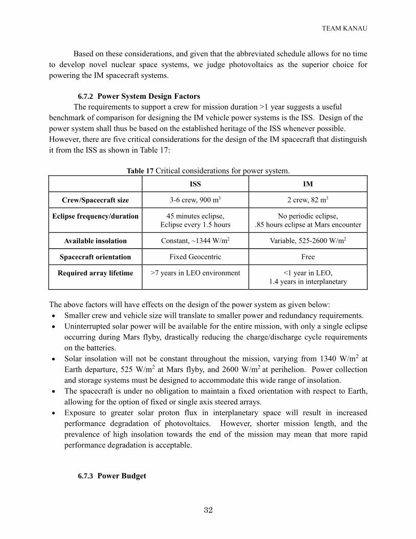
6.7.2 Power System Design Factors
The requirements to support a crew for mission duration >1 year suggests a useful
benchmark of comparison for designing the IM vehicle power systems is the ISS. Design of the
power system shall thus be based on the established heritage of the ISS whenever possible.
However, there are five critical considerations for the design of the IM spacecraft that distinguish
it from the ISS as shown in Table 17:
Table 17 Critical considerations for power system.
ISS IM
Crew/Spacecraft size 3-6 crew, 900 m3 2 crew, 82 m3
Eclipse frequency/duration 45 minutes eclipse,
Eclipse every 1.5 hours
No periodic eclipse,
.85 hours eclipse at Mars encounter
Available insolation Constant, ~1344 W/m2 Variable, 525-2600 W/m2
Spacecraft orientation Fixed Geocentric Free
Required array lifetime >7 years in LEO environment <1 year in LEO,
1.4 years in interplanetary
The above factors will have effects on the design of the power system as given below:
Smaller crew and vehicle size will translate to smaller power and redundancy requirements.
Uninterrupted solar power will be available for the entire mission, with only a single eclipse
occurring during Mars flyby, drastically reducing the charge/discharge cycle requirements
on the batteries.
Solar insolation will not be constant throughout the mission, varying from 1340 W/m2 at
Earth departure, 525 W/m2 at Mars flyby, and 2600 W/m2 at perihelion. Power collection
and storage systems must be designed to accommodate this wide range of insolation.
The spacecraft is under no obligation to maintain a fixed orientation with respect to Earth,
allowing for the option of fixed or single axis steered arrays.
Exposure to greater solar proton flux in interplanetary space will result in increased
performance degradation of photovoltaics. However, shorter mission length, and the
prevalence of high insolation towards the end of the mission may mean that more rapid
performance degradation is acceptable.
6.7.3 Power Budget
TEAM KANAU
33
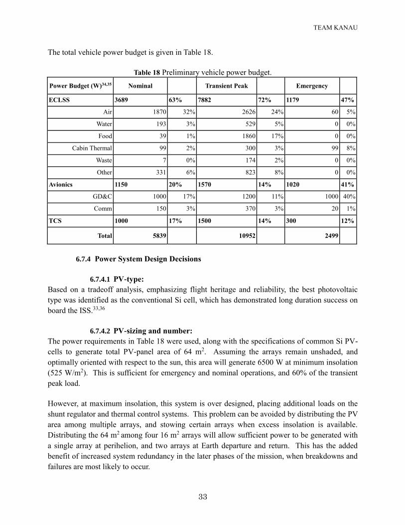
The total vehicle power budget is given in Table 18.
Table 18 Preliminary vehicle power budget.
Power Budget (W)34,35 Nominal Transient Peak Emergency
ECLSS 3689 63% 7882 72% 1179 47%
Air 1870 32% 2626 24% 60 5%
Water 193 3% 529 5% 0 0%
Food 39 1% 1860 17% 0 0%
Cabin Thermal 99 2% 300 3% 99 8%
Waste 7 0% 174 2% 0 0%
Other 331 6% 823 8% 0 0%
Avionics 1150 20% 1570 14% 1020 41%
GD&C 1000 17% 1200 11% 1000 40%
Comm 150 3% 370 3% 20 1%
TCS 1000 17% 1500 14% 300 12%
Total 5839 10952 2499
6.7.4 Power System Design Decisions
6.7.4.1 PV-type:
Based on a tradeoff analysis, emphasizing flight heritage and reliability, the best photovoltaic
type was identified as the conventional Si cell, which has demonstrated long duration success on
board the ISS.33,36
6.7.4.2 PV-sizing and number:
The power requirements in Table 18 were used, along with the specifications of common Si PV-
cells to generate total PV-panel area of 64 m2. Assuming the arrays remain unshaded, and
optimally oriented with respect to the sun, this area will generate 6500 W at minimum insolation
(525 W/m2). This is sufficient for emergency and nominal operations, and 60% of the transient
peak load.
However, at maximum insolation, this system is over designed, placing additional loads on the
shunt regulator and thermal control systems. This problem can be avoided by distributing the PV
area among multiple arrays, and stowing certain arrays when excess insolation is available.
Distributing the 64 m2 among four 16 m2 arrays will allow sufficient power to be generated with
a single array at perihelion, and two arrays at Earth departure and return. This has the added
benefit of increased system redundancy in the later phases of the mission, when breakdowns and
failures are most likely to occur.
TEAM KANAU
34
6.7.4.3 Battery Selection:
The selection of a NiMH battery chemistry for the ISS is driven by their high energy density and
charge cycle lifetime.33,36 However, Li batteries offer superior energy density, and are superior to
NiMH in virtually every respect except for charge cycle lifetime. The lack of regular eclipses in
the IM mission means the batteries are unlikely to be extensively cycled, and superior energy
density becomes a decisive advantage. Li-Ion or Li-Pol chemistry batteries are identified to be
the best alternative battery chemistry for powering the IM spacecraft systems. Based on the
required power levels, and the duration of an expected emergency and eclipse, four 8-cell 28V
Li-Ion batteries are identified as sufficient to provide the current, power and energy requirements
for the IM spacecraft.
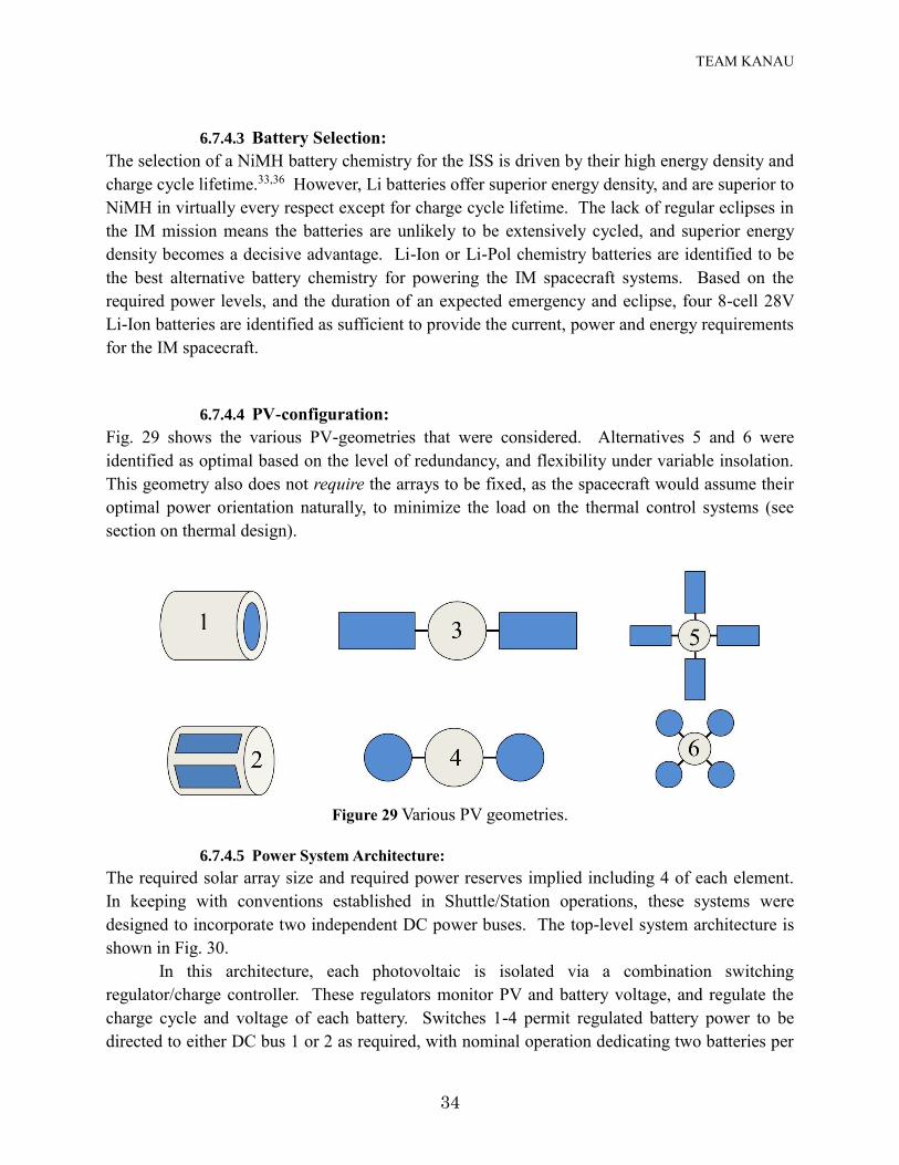
6.7.4.4 PV-configuration:
Fig. 29 shows the various PV-geometries that were considered. Alternatives 5 and 6 were
identified as optimal based on the level of redundancy, and flexibility under variable insolation.
This geometry also does not require the arrays to be fixed, as the spacecraft would assume their
optimal power orientation naturally, to minimize the load on the thermal control systems (see
section on thermal design).
Figure 29 Various PV geometries.
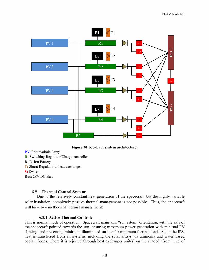
6.7.4.5 Power System Architecture:
The required solar array size and required power reserves implied including 4 of each element.
In keeping with conventions established in Shuttle/Station operations, these systems were
designed to incorporate two independent DC power buses. The top-level system architecture is
shown in Fig. 30.
In this architecture, each photovoltaic is isolated via a combination switching
regulator/charge controller. These regulators monitor PV and battery voltage, and regulate the
charge cycle and voltage of each battery. Switches 1-4 permit regulated battery power to be
directed to either DC bus 1 or 2 as required, with nominal operation dedicating two batteries per
TEAM KANAU
35
bus. When the load from a given battery is not required, charging takes place. When charging is
complete, excess power is rejected via a shunt to the heat exchanger.
Nominal operation calls for direct power supplied to buses 1 and 2 from photovoltaics 1
and 4, with batteries 1 and 4 used to provide transient loads as required. Photovoltaics 3 and 4
are used in this mode to maintain charge of batteries 3 and 4, with surplus power dissipated via
the heat exchanger.
This architecture is designed to be highly flexible and provide complete double fault
redundancy. During low insolation portions of the mission, a single component may fail and
nominal power levels can still be maintained, while the fault of any two components will still
permit emergency power to be available.
During high insolation portions of the mission, the entire spacecraft can be powered from
a single photovoltaic/battery, with transient power provided by a second battery is required. Any
two components may fail and nominal power will still be maintained.
In the event of an entire battery system failure, emergency power is available anytime in
the mission via regulator 5, which provides the option of supplying unregulated power from the
solar arrays. Such a contingency would not permit transient loads, and should be considered as a
backup system in the event of catastrophic battery damage.
TEAM KANAU
36
Figure 30 Top-level system architecture. PV: Photovoltaic Array
R: Switching Regulator/Charge controller
B: Li-Ion Battery
T: Shunt Regulator to heat exchanger
S: Switch
Bus: 28V DC Bus.
6.8 Thermal Control Systems
Due to the relatively constant heat generation of the spacecraft, but the highly variable
solar insolation, completely passive thermal management is not possible. Thus, the spacecraft
will have two methods of thermal management:
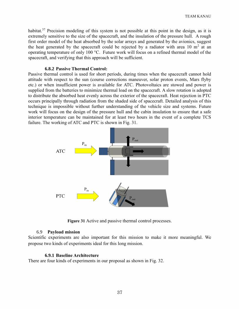
6.8.1 Active Thermal Control: This is normal mode of operation. Spacecraft maintains “sun astern” orientation, with the axis of
the spacecraft pointed towards the sun, ensuring maximum power generation with minimal PV
slewing, and presenting minimum illuminated surface for minimum thermal load. As on the ISS,
heat is transferred from all systems, including the solar arrays via ammonia and water based
coolant loops, where it is rejected through heat exchanger unit(s) on the shaded “front” end of
TEAM KANAU
37
habitat.37 Precision modeling of this system is not possible at this point in the design, as it is
extremely sensitive to the size of the spacecraft, and the insulation of the pressure hull. A rough
first order model of the heat absorbed by the solar arrays and generated by the avionics, suggest
the heat generated by the spacecraft could be rejected by a radiator with area 10 m2 at an
operating temperature of only 100 °C. Future work will focus on a refined thermal model of the
spacecraft, and verifying that this approach will be sufficient.
6.8.2 Passive Thermal Control:
Passive thermal control is used for short periods, during times when the spacecraft cannot hold
attitude with respect to the sun (course corrections maneuver, solar proton events, Mars flyby
etc.) or when insufficient power is available for ATC. Photovoltaics are stowed and power is
supplied from the batteries to minimize thermal load on the spacecraft. A slow rotation is adopted
to distribute the absorbed heat evenly across the exterior of the spacecraft. Heat rejection in PTC
occurs principally through radiation from the shaded side of spacecraft. Detailed analysis of this
technique is impossible without further understanding of the vehicle size and systems. Future
work will focus on the design of the pressure hull and the cabin insulation to ensure that a safe
interior temperature can be maintained for at least two hours in the event of a complete TCS
failure. The working of ATC and PTC is shown in Fig. 31.
Figure 31 Active and passive thermal control processes.
6.9 Payload mission
Scientific experiments are also important for this mission to make it more meaningful. We
propose two kinds of experiments ideal for this long mission.
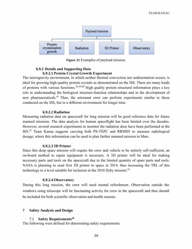
6.9.1 Baseline Architecture
There are four kinds of experiments in our proposal as shown in Fig. 32.
TEAM KANAU
38
Figure 32 Examples of payload mission.
6.9.2 Details and Supporting Data
6.9.2.1 Protein Crystal Growth Experiment
The microgravity environment, in which neither thermal convection nor sedimentation occurs, is
ideal for growing high-quality protein crystals as demonstrated on the ISS. There are many kinds
of proteins with various functions.38,39,40 High quality protein structural information plays a key
role in understanding the biological structure-function relationships and in the development of
new pharmaceuticals.41 Thus, the astronaut crew can perform experiments similar to those
conducted on the ISS, but in a different environment for longer time.
6.9.2.2 Radiation
Measuring radiation data on spacecraft for long mission will be good reference data for future
manned missions. The data analysis for human spaceflight has been limited over the decades.
However, several research experiments to monitor the radiation dose have been performed at the
ISS.42 Team Kanau suggests carrying both PS-TEPC and RRMD3 to measure radiological
dosage, where this information can be used to plan further manned mission to Mars.
6.9.2.3 3D Printer
Since this deep space mission will require the crew and vehicle to be entirely self-sufficient, an
on-board method to repair equipment is necessary. A 3D printer will be ideal for making
necessary parts and tools on the spacecraft due to the limited quantity of spare parts and tools.
NASA is planning to send first 3D printer to space in 2014, thus increasing the TRL of this
technology to a level suitable for inclusion in the 2018 flyby mission.43
6.9.2.4 Observatory
During this long mission, the crew will need mental refreshment. Observation outside the
windows using telescope will be fascinating activity for crew in the spacecraft and thus should
be included for both scientific observation and health reasons.
7 Safety Analysis and Design
7.1 Safety Requirements44
The following were defined for determining safety requirements.
TEAM KANAU
39
7.1.1 Mission Success: to perform a flyby of two crewmembers around Mars and return
them safely to Earth.
7.1.2 Safety Goal: to identify all possible safety hazards, to eliminate/control them to
an acceptable level during all the phases of the mission.
7.1.3 Probabilistic Goals: to have risk requirement of around 0.5% for human mission
to Mars.
Table 19 describes the safety requirements for the Inspiration Mars mission.
Table 19 Safety requirements for Inspiration Mars mission.
Failure Category Definition Failure Tolerance Level
Catastrophic
Disabling or fatal personnel injury, loss
of elements of vehicle stack or major
ground facility.
Double-failure tolerant
Critical
Non-disabling personnel injury, major
occupational illness, loss of elements
not in critical path.
Single-failure tolerant
Marginal Damage to emergency system, minor
personnel injury or occupational illness.
Other concepts required are given below:
The Fail Op/Fail Op Concept: The system or function to which this concept is applied
maintains functionality after the first and second failure.
The Fail Op/Fail Safe Concept: The “critical” system or function to which this concept is
applied maintains functionality after the first failure but not after second.
The Fail Safe/Fail Safe Concept: The functionality is not maintained after any failure but
no hazardous consequence occurs after two failures.
7.2 Abort options45
Detailed investigations of Martian human mission risks have not yet been performed. Abort
options are designed into the mission for as many phases as possible to achieve acceptable risks
as shown in Table 20.
Table 20 Abort possibilities.
Phases Options
Earth Departure Return to Earth possible
Early Part of Transfer to Mars No practical abort scheme
Later Part of Transfer to Mars No practical abort scheme
Transfer to Earth Continue normal return to Earth
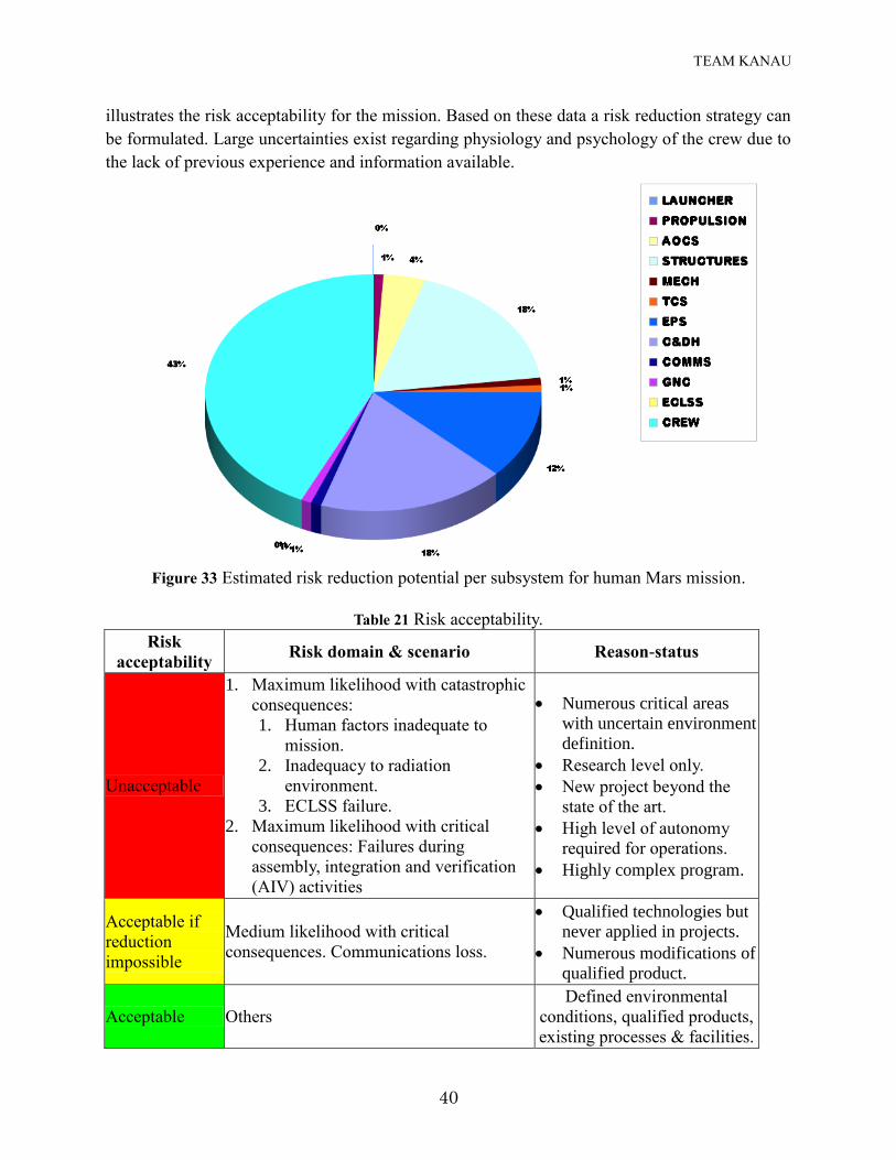
7.3 Risk acceptability45,46
For human missions to Mars the estimated risk reduction potential is shown in Fig. 33. Table 21
TEAM KANAU
40
illustrates the risk acceptability for the mission. Based on these data a risk reduction strategy can
be formulated. Large uncertainties exist regarding physiology and psychology of the crew due to
the lack of previous experience and information available.
Figure 33 Estimated risk reduction potential per subsystem for human Mars mission.
Table 21 Risk acceptability.
Risk
acceptability Risk domain & scenario Reason-status
Unacceptable
1. Maximum likelihood with catastrophic
consequences:
1. Human factors inadequate to
mission.
2. Inadequacy to radiation
environment.
3. ECLSS failure.
2. Maximum likelihood with critical
consequences: Failures during
assembly, integration and verification
(AIV) activities
Numerous critical areas
with uncertain environment
definition.
Research level only.
New project beyond the
state of the art.
High level of autonomy
required for operations.
Highly complex program.
Acceptable if
reduction
impossible
Medium likelihood with critical
consequences. Communications loss.
Qualified technologies but
never applied in projects.
Numerous modifications of
qualified product.
Acceptable Others
Defined environmental
conditions, qualified products,
existing processes & facilities.
TEAM KANAU
41
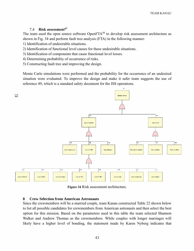
7.4 Risk assessment47
The team used the open source software OpenFTA48 to develop risk assessment architecture as
shown in Fig. 34 and perform fault tree analysis (FTA) in the following manner:
1) Identification of undesirable situations.
2) Identification of functional level causes for these undesirable situations.
3) Identification of components that cause functional level losses.
4) Determining probability of occurrence of risks.
5) Constructing fault tree and improving the design.
Monte Carlo simulations were performed and the probability for the occurrence of an undesired
situation were evaluated. To improve the design and make it safer team suggests the use of
reference 49, which is a standard safety document for the ISS operations.
Figure 34 Risk assessment architecture.
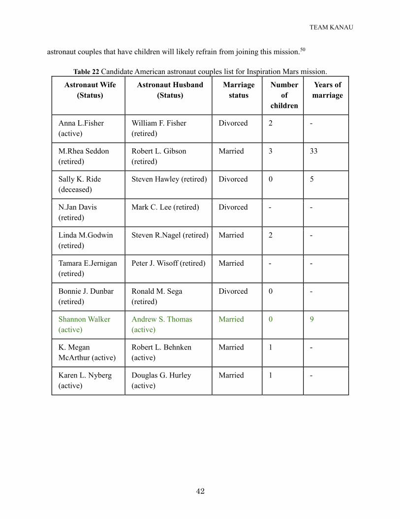
8 Crew Selection from American Astronauts
Since the crewmembers will be a married couple, team Kanau constructed Table 22 shown below
to list all possible candidates for crewmembers from American astronauts and then select the best
option for this mission. Based on the parameters used in this table the team selected Shannon
Walker and Andrew Thomas as the crewmembers. While couples with longer marriages will
likely have a higher level of bonding, the statement made by Karen Nyberg indicates that
TEAM KANAU
42
astronaut couples that have children will likely refrain from joining this mission.50
Table 22 Candidate American astronaut couples list for Inspiration Mars mission.
Astronaut Wife
(Status)
Astronaut Husband
(Status)
Marriage
status
Number
of
children
Years of
marriage
Anna L.Fisher
(active)
William F. Fisher
(retired)
Divorced 2 -
M.Rhea Seddon
(retired)
Robert L. Gibson
(retired)
Married 3 33
Sally K. Ride
(deceased)
Steven Hawley (retired) Divorced 0 5
N.Jan Davis
(retired)
Mark C. Lee (retired) Divorced - -
Linda M.Godwin
(retired)
Steven R.Nagel (retired) Married 2 -
Tamara E.Jernigan
(retired)
Peter J. Wisoff (retired) Married - -
Bonnie J. Dunbar
(retired)
Ronald M. Sega
(retired)
Divorced 0 -
Shannon Walker
(active)
Andrew S. Thomas
(active)
Married 0 9
K. Megan
McArthur (active)
Robert L. Behnken
(active)
Married 1 -
Karen L. Nyberg
(active)
Douglas G. Hurley
(active)
Married 1 -
TEAM KANAU
43
9 Conclusion
Team Kanau’s architecture for a two-person flyby mission of Mars in the year 2018
presents opportunities for the incorporation of many intriguing technologies and techniques
for the 501 day crewed journey. We propose astronauts Shannon Walker and Andrew S.
Thomas, a married couple of 9 years, as the crew of the spacecraft. Three Falcon Heavy
launches will deliver the crewed capsule, along with the required ACES propulsion stages
for the Trans-Mars Injection, to a LEO staging orbit; this launch program relies only upon
current or near-term technologies from SpaceX and United Launch Alliance, and so reduces
the risk of delays to the schedule and offers significant cost savings compared to other
available launch systems. Aerocapture upon return to the Earth will mitigate high re-entry
velocities and enable the use of a SpaceX Dragon capsule for the crew re-entry and descent
to the surface of the Earth.
We consider several factors to maintain the physical, mental, and emotional well- being
of the married astronauts. Adequate space and privacy are provided within the capsule, and
a robust communications system is designed to minimize the chance of crew isolation from
Earth. We propose a regenerative oxygen and carbon dioxide recycling system based upon
the International Space Station with a back-up set of compressed storage tanks for air
circulation. This hybrid approach reduces system mass whilst ensuring a continued supply of
fresh, breathable air. While most food for the crew will be pre-prepared and packaged, a
limited supply of fresh vegetables and seasonings can be grown on-board; in addition to
providing variety to the crew diet, the growing and nurturing of the plants will give needed
mental stimulation and a psychological connection to Earth for the married couple.
Incidental tools and equipment for the crew can be manufactured on-board via the use of 3-
D printing, a technology that has been demonstrated in micro-gravity environments upon the
ISS. Simulations of the ECLSS are performed using SICLE, the Simulator for Closed Life
and Ecology. These novel human factors technologies, along with the proposed launch and
Earth return scenarios, are key components that enable deep space human missions, for
example the proposed crewed flyby of Mars in 2018, in both the near- and far-term.
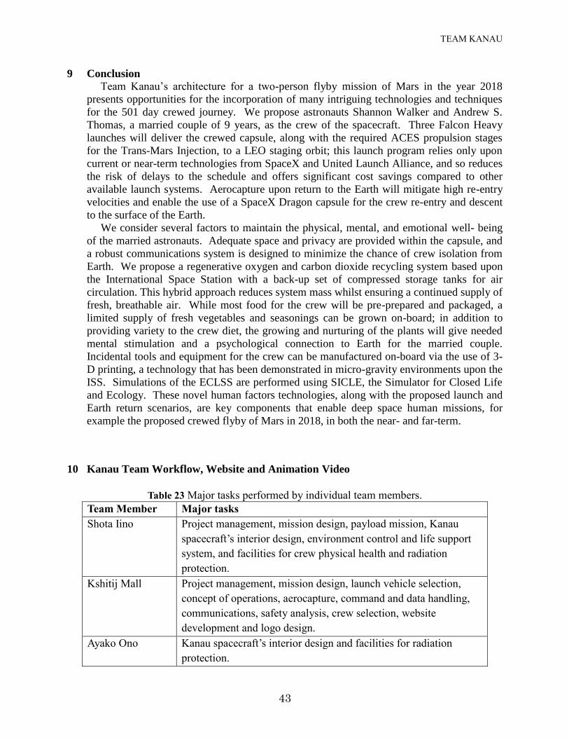
10 Kanau Team Workflow, Website and Animation Video
Table 23 Major tasks performed by individual team members.
Team Member Major tasks
Shota Iino Project management, mission design, payload mission, Kanau
spacecraft’s interior design, environment control and life support
system, and facilities for crew physical health and radiation
protection.
Kshitij Mall Project management, mission design, launch vehicle selection,
concept of operations, aerocapture, command and data handling,
communications, safety analysis, crew selection, website
development and logo design.
Ayako Ono Kanau spacecraft’s interior design and facilities for radiation
protection.
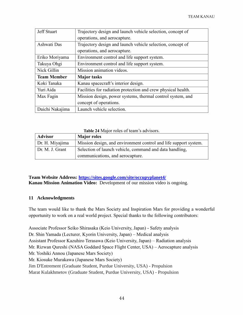
TEAM KANAU
44
Jeff Stuart Trajectory design and launch vehicle selection, concept of
operations, and aerocapture.
Ashwati Das Trajectory design and launch vehicle selection, concept of
operations, and aerocapture.
Eriko Moriyama Environment control and life support system.
Takuya Ohgi Environment control and life support system.
Nick Gillin Mission animation videos.
Team Member Major tasks
Koki Tanaka Kanau spacecraft’s interior design.
Yuri Aida Facilities for radiation protection and crew physical health.
Max Fagin Mission design, power systems, thermal control system, and
concept of operations.
Daichi Nakajima Launch vehicle selection.
Table 24 Major roles of team’s advisors.
Advisor Major roles
Dr. H. Miyajima Mission design, and environment control and life support system.
Dr. M. J. Grant Selection of launch vehicle, command and data handling,
communications, and aerocapture.
Team Website Address: https://sites.google.com/site/occupyplanet4/
Kanau Mission Animation Video: Development of our mission video is ongoing.
11 Acknowledgments
The team would like to thank the Mars Society and Inspiration Mars for providing a wonderful
opportunity to work on a real world project. Special thanks to the following contributors:
Associate Professor Seiko Shirasaka (Keio University, Japan) - Safety analysis
Dr. Shin Yamada (Lecturer, Kyorin University, Japan) – Medical analysis
Assistant Professor Kazuhiro Terasawa (Keio University, Japan) – Radiation analysis
Mr. Rizwan Qureshi (NASA Goddard Space Flight Center, USA) – Aerocapture analysis
Mr. Yoshiki Annou (Japanese Mars Society)
Mr. Kiosuke Murakawa (Japanese Mars Society)
Jim D'Entrement (Graduate Student, Purdue University, USA) - Propulsion
Marat Kulakhmetov (Graduate Student, Purdue University, USA) - Propulsion
TEAM KANAU
45
Dr. Stephen D. Heister (Professor, Purdue University, USA) - Propulsion
Mr. Isaac Cooper (Machinimist, New Zealand) – Animation video
12 References 1Houser, J. R. and Clausing, D.,“House of Quality,” IEEE Management Review, Spring 1996. 2Patel, M. R., Longuski, J. M., and Sims, J. A. “Mars Free Return Trajectories”, Journal of
Spacecraft and Rockets, Vol. 35, No. 3, May-Jun 1998, pp. 350-354. 3Tito, D. A. et al. “Feasibility Analysis for a Manned Mars Free-Return Mission in 2018”, IEEE
Aerospace Conference, Big Sky, Montana 2 Mar. 2013. 4Inspiration Mars “Architecture Study Report Summary”, Document No. 806800151NC, 20 Nov.
2013. 5 Schooley, M., “Fuel Propellants – Storable, and Hypergolic vs. Ignitable”, The Permanent
Space Development Foundation, URL: http://www.permanent.com/. Accessed 9 Mar. 2014. 6Prince, J. L. H., Powell, R. W. and Murri, D., "Autonomous Aerobraking: A Design,
Development, and Feasibility Study" NASA Langley Research Center, NASA Technical Reports
Server. Retrieved 5 Mar. 2014. 7GMAT, General Mission Analysis Tool, Software Package, R2012a, NASA GSFC, Greenbelt,
MD, Sep. 2013. 8Lyne, J. E., Tauber, M. E. and Braun, R. D., "Parametric study of Manned Aerocapture Part I:
Earth Return from Mars" JOURNAL OF SPACECRAFT AND ROCKETS, Vol. 29, No. 6, Nov-
Dec, 1992. 9Trevino, L., "SpaceX Dragon Re-Entry Vehicle: Aerodynamics and Aerothermodynamics with
Application to Base Heat-Shield Design" 6th International Planetary Probe Workshop
Conference Proceedings, Atlanta, Georgia, 21‐27 Jun. 2008.
10Levri, A. J., “Advanced Life Support Equivalent System Mass Guidelines Document,” NASA,
TM-2003-212278, 2003. 11Hanford, A. J., “Advanced Life Support Baseline Values and Assumptions Document,” NASA,
CR-2004-208941, 2004. 12Hanford, A. J., “Advanced Life Support Research and Technology Development Metric - Fiscal
year 2005,” NASA, CR-2006-213694, 2006. 13Javanmardian, M. and Palsson, B. O., “DESIGN AND OPERATION OF AN ALGAL
PHOTOBIOREACTOR SYSTEM,” Advances in Space Research, Vol. 12, No. 5, 1992, pp. 231-
235. 14Living Farm, URL: http://www.living-farm.com/ 15Hirosaki, T. et al. “Developing the Simulator of Material Circulation Control System, SICLE,”
Proceedings of 2013 SEE Conference, The Society of Eco-Engineering, 2013, pp. 67,68. 16NASA (2007) NASA-STD-3001 NASA SPACE FLIGHT HUMAN SYSTEM STANDARD
VOLUME 1: CREW HEALTH, VOLUME 2: HUMAN FACTORS, HABITABILITY, AND
ENVIRONMENTAL HEALTH. 17Schlacht, I. L. “Color design requirement in microgravity long duration mission,” Proceeding
TEAM KANAU
46
of International Astronautical Congress, Paper: IAC-06-A1.P.1.06, 2006. 18Ono, A. et al., “Designing Crew Habitats for Long Term Physical and Psychological Health
and Radiation Safety,” IAA Space Exploration Conference, Planetary Robotic and Human
Spaceflight Exploration, 2014. 19Ono, A., Irene Lia Schlacht. “Space art: aesthetics design as psychological support,” Personal
and Ubiquitous Computing, Vol. 15, No. 5, pp. 513-517 20Schlacht, I. L., Birke, H., “Space design visual interface of space habitats” Personal and
Ubiquitous Computing, Vol. 15, No. 5, pp. 498-503 21Schlacht, I. L., et al. "Human factors in space mission," A. Lichtenstein, C. Stößel, & C.
Clemens (a cura di)(Eds.), Der Mensch im Mittelpunkt technischer Systeme 8, 2009, pp. 326-330. 22NASA-STD-3001 NASA SPACE FLIGHT HUMAN SYSTEM STANDARD VOLUME 1:
CREW HEALTH, VOLUME 2: HUMAN FACTORS, HABITABILITY, AND
ENVIRONMENTAL HEALTH, 2007. 23Trappe, S. et al. "Exercise in space: human skeletal muscle after 6 months aboard the
International Space Station," Journal of Applied Physiology, 106.4: 1159-1168, 12 Jan. 2009. 24McPhee, J.C. and Charles, J. B., “Human health and performance risks of space exploration
missions,” NASA. 25Matsumoto, T., “Space Medicine Contributes to Medical Advances on Earth,” JAXA, URL:
http://www.jaxa.jp/article/special/expedition/matsumoto01_e.html 26NASA-STD-3001 NASA SPACE FLIGHT HUMAN SYSTEM STANDARD VOLUME 1:
CREW HEALTH, VOLUME 2: HUMAN FACTORS, HABITABILITY, AND
ENVIRONMENTAL HEALTH, 2007. 27Ono, A. et al. “Designing Crew Habitats for Long Term Physical and Psychological Health and
Radiation Safety,” IAA Space Exploration Conference, Planetary Robotic and Human Spaceflight
Exploration, 2014. 28Kodaira, S. et al. “Verification of shielding effect by the water-filled materials for space
radiation in the International Space Station using passive dosimeters,” 2013. 29Berger, M., “Nanofoams are promising materials for radiation shielding,” Nanowerk, 15 Jun.
2011. URL: http://www.nanowerk.com/spotlight/spotid=21747.php/. Accessed 17 Dec. 2013. 30“CDF STUDY REPORT HUMAN MISSION TO MARS” ESA, pp.196-217. 31“PROCESSORS 100 YEARS OF SPACE OPERATION” BAE Systems. 32“Frequency assignment guidelines for communications in the Mars region” Space Frequency
Coordination Group, recommendation 22-1R1. 33Pisacane, V. L., Fundamentals of space systems, Oxford; New York: Oxford University Press,
2005. 34“Miyajima, H. and Klaus, D., "Feasibility Analysis of Spacecraft Design for a Manned Mars
Free-Return Mission in 2018,” International Conference on Environmental Systems, Tucson,
Arizona, 13-17 Jul. 2014 (submitted). 35Tito, D. et al. Feasibility Analysis of Spacecraft Design for a Manned Mars Free-Return
Mission in 2018."
TEAM KANAU
47
36Wertz, J. R., and Larson, W. J., Space mission analysis and design, Torrance, Calif.; Dordrecht;
Boston: Microcosm ; Kluwer, 1999. 37“ISS Interactive Reference Guide, ECLSS," URL: www.nasa.gov/. 38“Protein Crystal Growth - Single Locker Thermal Enclosure System (PCG-STES),” URL:
http://www.nasa.gov/mission_pages/station/research/experiments/679.html/. 39“Advancing Membrane Protein Crystallization By Using Microgravity (CASIS PCG HDPCG-
2)” URL: http://www.nasa.gov/mission_pages/station/research/experiments/1315.html/. 40“Japan Aerospace Exploration Agency Protein Crystal Growth (JAXA PCG),” URL:
http://www.nasa.gov/mission_pages/station/research/experiments/157.html/. 41DeLucas, L. J., Moore, M. K, and Long, M. M., "Protein crystal growth and the International
Space Station." Gravitational and Space Research 12.2, 2007. 42“Area Passive Dosimeter for Life-Science Experiments in Space (Area PADLES),” URL:
http://www.nasa.gov/mission_pages/station/research/experiments/901.html/. 43“Nasa plans first 3D printer space launch in 2014,” URL:
http://www.bbc.com/news/technology-24329296/. 44Musgrave, G., Larsen, A. and Sgobba, T., "Safety design for Space Systems" International
Association for the Advancement of Space. 45“CDF STUDY REPORT HUMAN MISSION TO MARS,” ESA, pp.101-105. 46“Risk management,” EUROPEAN COOPERATION FOR SPACE STANDARDIZATION, pp.
22, 25 Apr. 2000. 47“Fault Tree Handbook with Aerospace Applications" Version 1.1, NASA Publication, Aug.
2002. 48OpenFTA, Ver. 1.0, Auvation, Cardiff, Wales, UK, Feb. 2005. 49SSP 50038B, COMPUTER-BASED CONTROL SYSTEM SAFETY REQUIREMENTS -
INTERNATIONAL SPACE STATION, 17 Nov. 1995. 50Berger, E., “Will NASA’s married astronauts be considered for the private Mars mission?”
Sciguy, Chron, 19 Mar. 2013. URL: http://blog.chron.com/sciguy/2013/03/will-nasas-married-
astronauts-be-considered-for-the-private-mars-mission/. Accessed 9 Mar. 2014.

TEAM KANAU
48
Appendix A
Table 1 Comparison between aerobraking and aerocapture techniques.
Aerobraking Aerocapture
1. Performed for around 6 months. 1. Performed for a few minutes.
2. Requires lighter and thinner thermal
protection system.
2. Requires heavier and thicker thermal
protection system.
3. Demonstrated four times by NASA.1 3. Never demonstrated before.
4. Suitable for robotic/cargo missions. 4. Suitable for human space missions.
Table 2 ESM breakdown for bio-regenerative systems.
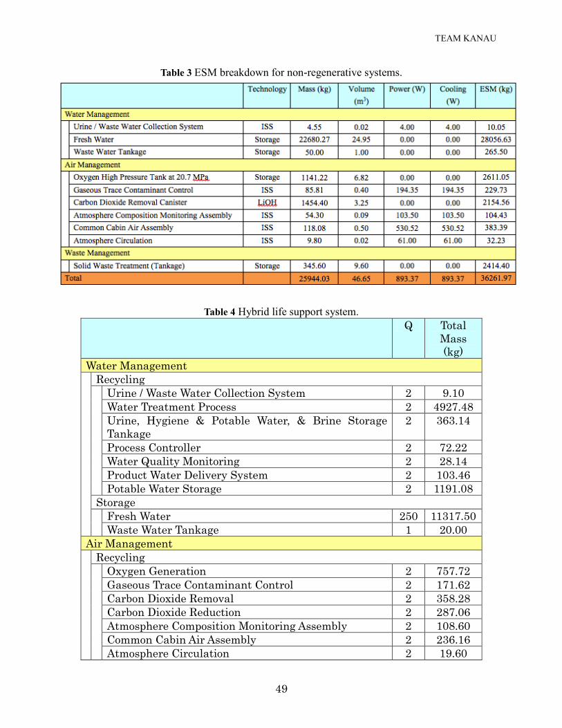
TEAM KANAU
49
Table 3 ESM breakdown for non-regenerative systems.
Table 4 Hybrid life support system.
Q Total
Mass
(kg)
Water Management
Recycling
Urine / Waste Water Collection System 2 9.10
Water Treatment Process 2 4927.48
Urine, Hygiene & Potable Water, & Brine Storage
Tankage
2 363.14
Process Controller 2 72.22
Water Quality Monitoring 2 28.14
Product Water Delivery System 2 103.46
Potable Water Storage 2 1191.08
Storage
Fresh Water 250 11317.50
Waste Water Tankage 1 20.00
Air Management
Recycling
Oxygen Generation 2 757.72
Gaseous Trace Contaminant Control 2 171.62
Carbon Dioxide Removal 2 358.28
Carbon Dioxide Reduction 2 287.06
Atmosphere Composition Monitoring Assembly 2 108.60
Common Cabin Air Assembly 2 236.16
Atmosphere Circulation 2 19.60
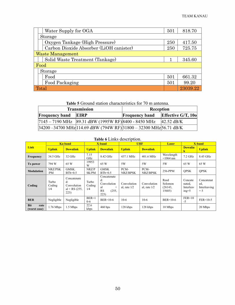
TEAM KANAU
50
Water Supply for OGA 501 818.70
Storage
Oxygen Tankage (High Pressure) 250 417.50
Carbon Dioxide Absorber (LiOH canister) 250 725.75
Waste Management
Solid Waste Treatment (Tankage) 1 345.60
Food
Storage
Food 501 661.32
Food Packaging 501 99.20
Total 23039.22
Table 5 Ground station characteristics for 70 m antenna.
Transmission Reception
Frequency band EIRP Frequency band Effective G/T, 10o
7145 – 7190 MHz 89.31 dBW (1995W RF) 8400 - 8450 MHz 42.52 dB/K
34200 –34700 MHz 114.69 dBW (794W RF) 31800 – 32300 MHz 56.71 dB/K
Table 6 Links description.
Link
Ka-band X-band UHF Laser X-band
Uplink Downlink Uplink Downlink Uplink Downlink Downlin
k Uplink
Frequency 34.5 GHz 32 GHz 7.15 GHz
8.42 GHz 437.1 MHz 401.6 MHz Wavelength =1064 nm
7.2 GHz 8.45 GHz
Tx power 794 W 65 W 19953
W 65 W 5W 5W 5W 65 W 65 W
Modulation NRZ/PSK/PM
GMSK. BTb=0.5
NRZ/PSK/PM
GMSK BTb=0.5
PCM- NRZ/BPSK
PCM- NRZ/BPSK
256-PPM QPSK QPSK
Coding
Turbo
Coding 1⁄4
Concatenated:
Convolutional + RS (255,
223)
Turbo
Coding 1⁄4
Concatenate
d:
Convolutional +
RS (255, 223)
Convolutional, rate 1⁄2
Convolutional, rate 1⁄2
Reed
Solomon (26143,
15685)
Concate
nated, Interleav
ing=5
Concatenat
ed, Interleaving
= 5
BER Negligible Negligible BER=1
0-6 BER=10-6 10-6 10-6 BER=10-6
FER=10
-5 FER=10-5
Bit rate
(worst case) 1.76 Mbps 1.5 Mbps
22.6 kbps
460 bps 128 kbps 128 kbps 10 Mbps
20 Mbps
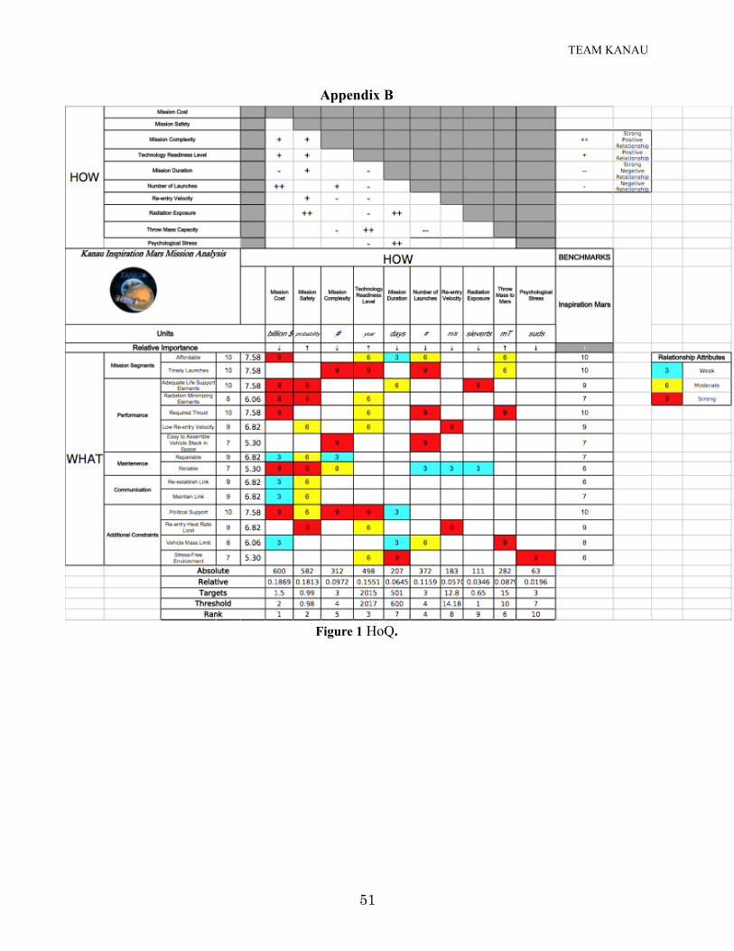
TEAM KANAU
51
Appendix B
Figure 1 HoQ.
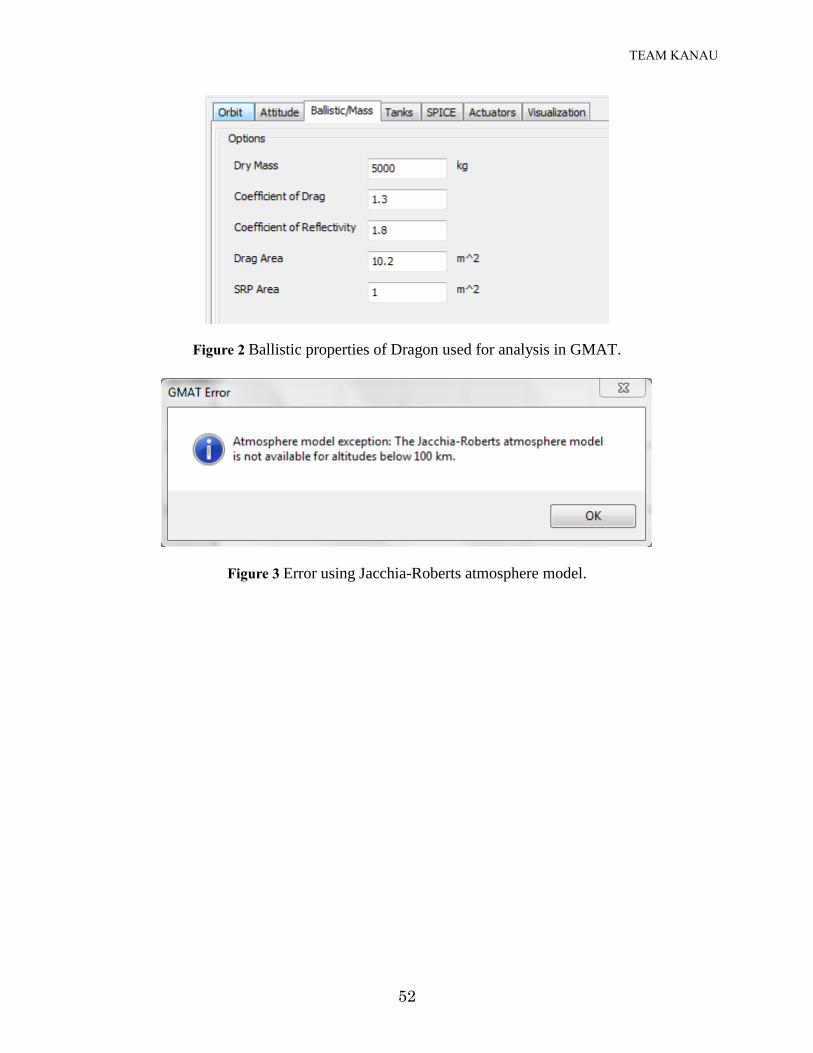
TEAM KANAU
52
Figure 2 Ballistic properties of Dragon used for analysis in GMAT.
Figure 3 Error using Jacchia-Roberts atmosphere model.
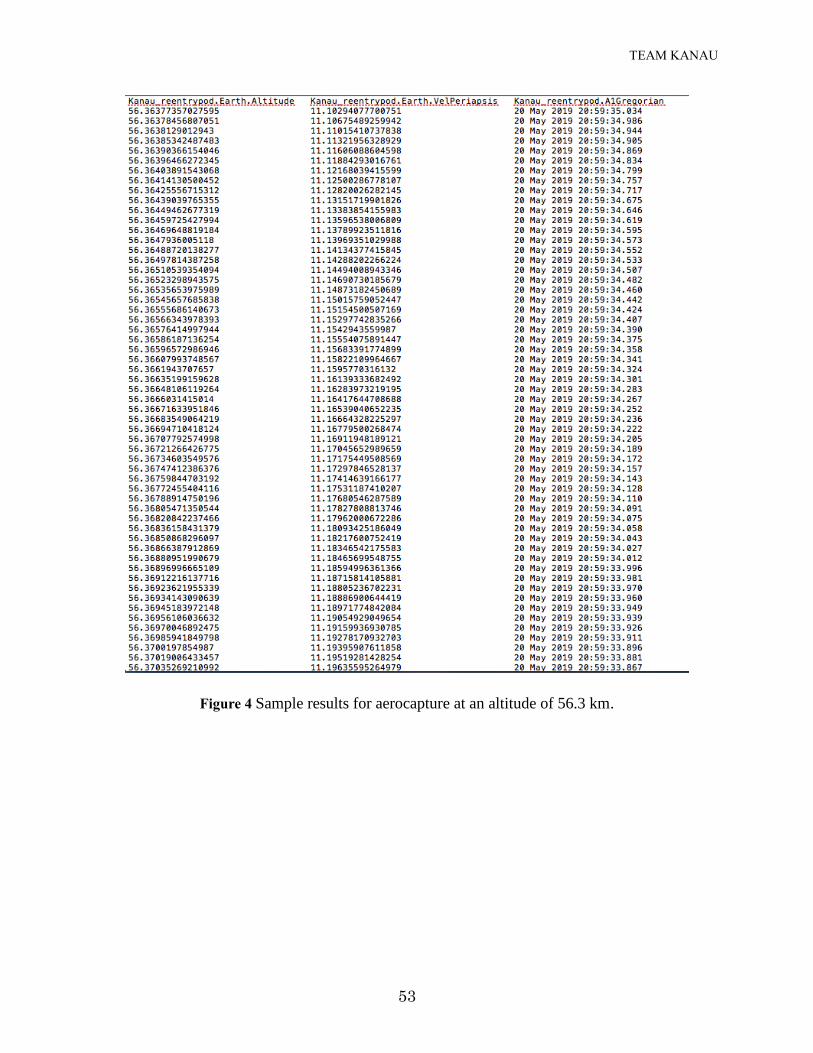
TEAM KANAU
53
Figure 4 Sample results for aerocapture at an altitude of 56.3 km.
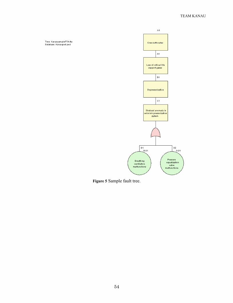
TEAM KANAU
54
Figure 5 Sample fault tree.
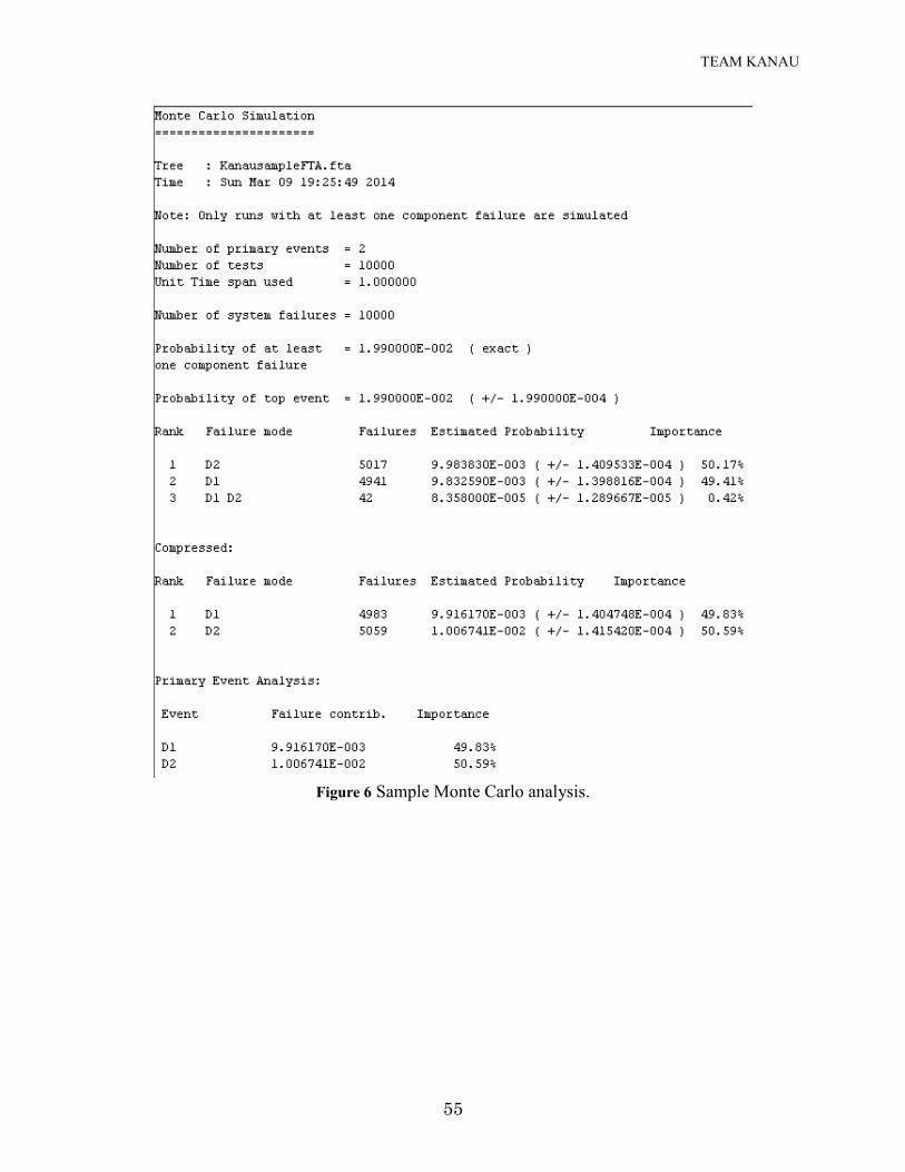
TEAM KANAU
55
Figure 6 Sample Monte Carlo analysis.

TEAM KANAU
56
Appendix C
%General Mission Analysis Tool(GMAT) Script %Created: 2014-03-03 02:50:18 %---------------------------------------- %---------- Spacecraft %---------------------------------------- Create Spacecraft Kanau_reentrypod; GMAT Kanau_reentrypod.DateFormat = UTCGregorian; GMAT Kanau_reentrypod.Epoch = '20 May 2019 20:59:00.000'; GMAT Kanau_reentrypod.CoordinateSystem = EarthMJ2000Eq; GMAT Kanau_reentrypod.DisplayStateType = Keplerian; GMAT Kanau_reentrypod.SMA = 643449.9999999778; GMAT Kanau_reentrypod.ECC = 0.9899999999999994; GMAT Kanau_reentrypod.INC = 0; GMAT Kanau_reentrypod.RAAN = 0; GMAT Kanau_reentrypod.AOP = 0; GMAT Kanau_reentrypod.TA = 0; GMAT Kanau_reentrypod.DryMass = 5000; GMAT Kanau_reentrypod.Cd = 1.3; GMAT Kanau_reentrypod.Cr = 1.8; GMAT Kanau_reentrypod.DragArea = 10.2; GMAT Kanau_reentrypod.SRPArea = 1; GMAT Kanau_reentrypod.NAIFId = -123456789; GMAT Kanau_reentrypod.NAIFIdReferenceFrame = -123456789; GMAT Kanau_reentrypod.Id = 'SatId'; GMAT Kanau_reentrypod.Attitude = CoordinateSystemFixed; GMAT Kanau_reentrypod.ModelFile = '../data/vehicle/models/aura.3ds'; GMAT Kanau_reentrypod.ModelOffsetX = 0; GMAT Kanau_reentrypod.ModelOffsetY = 0; GMAT Kanau_reentrypod.ModelOffsetZ = 0; GMAT Kanau_reentrypod.ModelRotationX = 0; GMAT Kanau_reentrypod.ModelRotationY = 0; GMAT Kanau_reentrypod.ModelRotationZ = 0; GMAT Kanau_reentrypod.ModelScale = 3; GMAT Kanau_reentrypod.AttitudeDisplayStateType = 'Quaternion'; GMAT Kanau_reentrypod.AttitudeRateDisplayStateType = 'AngularVelocity'; GMAT Kanau_reentrypod.AttitudeCoordinateSystem = EarthMJ2000Eq; GMAT Kanau_reentrypod.EulerAngleSequence = '321'; %---------------------------------------- %---------- ForceModels %---------------------------------------- Create ForceModel Kanau_reentry_prop_ForceModel; GMAT Kanau_reentry_prop_ForceModel.CentralBody = Earth; GMAT Kanau_reentry_prop_ForceModel.PrimaryBodies = {Earth}; GMAT Kanau_reentry_prop_ForceModel.PointMasses = {Luna, Sun}; GMAT Kanau_reentry_prop_ForceModel.SRP = Off; GMAT Kanau_reentry_prop_ForceModel.RelativisticCorrection = Off; GMAT Kanau_reentry_prop_ForceModel.ErrorControl = RSSStep; GMAT Kanau_reentry_prop_ForceModel.GravityField.Earth.Degree = 10; GMAT Kanau_reentry_prop_ForceModel.GravityField.Earth.Order = 10; GMAT Kanau_reentry_prop_ForceModel.GravityField.Earth.PotentialFile = 'JGM2.cof'; GMAT Kanau_reentry_prop_ForceModel.GravityField.Earth.EarthTideModel = 'None'; GMAT Kanau_reentry_prop_ForceModel.Drag.AtmosphereModel = MSISE90; GMAT Kanau_reentry_prop_ForceModel.Drag.F107 = 150;
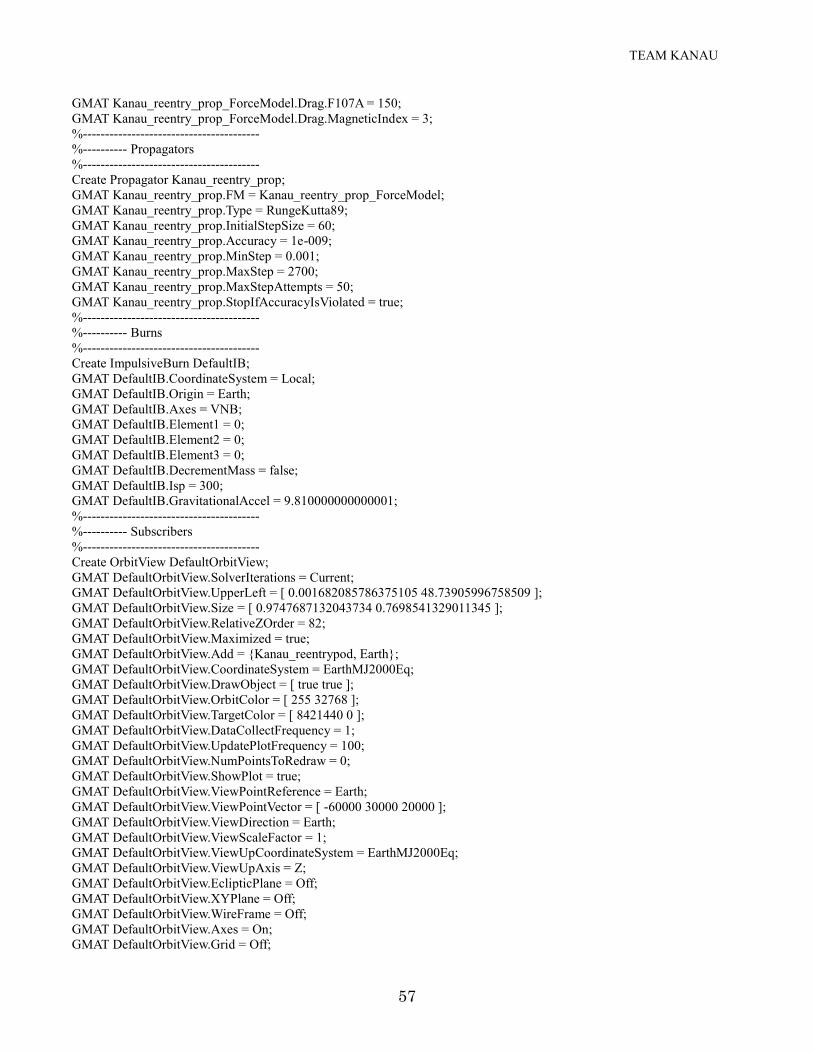
TEAM KANAU
57
GMAT Kanau_reentry_prop_ForceModel.Drag.F107A = 150; GMAT Kanau_reentry_prop_ForceModel.Drag.MagneticIndex = 3; %---------------------------------------- %---------- Propagators %---------------------------------------- Create Propagator Kanau_reentry_prop; GMAT Kanau_reentry_prop.FM = Kanau_reentry_prop_ForceModel; GMAT Kanau_reentry_prop.Type = RungeKutta89; GMAT Kanau_reentry_prop.InitialStepSize = 60; GMAT Kanau_reentry_prop.Accuracy = 1e-009; GMAT Kanau_reentry_prop.MinStep = 0.001; GMAT Kanau_reentry_prop.MaxStep = 2700; GMAT Kanau_reentry_prop.MaxStepAttempts = 50; GMAT Kanau_reentry_prop.StopIfAccuracyIsViolated = true; %---------------------------------------- %---------- Burns %---------------------------------------- Create ImpulsiveBurn DefaultIB; GMAT DefaultIB.CoordinateSystem = Local; GMAT DefaultIB.Origin = Earth; GMAT DefaultIB.Axes = VNB; GMAT DefaultIB.Element1 = 0; GMAT DefaultIB.Element2 = 0; GMAT DefaultIB.Element3 = 0; GMAT DefaultIB.DecrementMass = false; GMAT DefaultIB.Isp = 300; GMAT DefaultIB.GravitationalAccel = 9.810000000000001; %---------------------------------------- %---------- Subscribers %---------------------------------------- Create OrbitView DefaultOrbitView; GMAT DefaultOrbitView.SolverIterations = Current; GMAT DefaultOrbitView.UpperLeft = [ 0.001682085786375105 48.73905996758509 ]; GMAT DefaultOrbitView.Size = [ 0.9747687132043734 0.7698541329011345 ]; GMAT DefaultOrbitView.RelativeZOrder = 82; GMAT DefaultOrbitView.Maximized = true; GMAT DefaultOrbitView.Add = {Kanau_reentrypod, Earth}; GMAT DefaultOrbitView.CoordinateSystem = EarthMJ2000Eq; GMAT DefaultOrbitView.DrawObject = [ true true ]; GMAT DefaultOrbitView.OrbitColor = [ 255 32768 ]; GMAT DefaultOrbitView.TargetColor = [ 8421440 0 ]; GMAT DefaultOrbitView.DataCollectFrequency = 1; GMAT DefaultOrbitView.UpdatePlotFrequency = 100; GMAT DefaultOrbitView.NumPointsToRedraw = 0; GMAT DefaultOrbitView.ShowPlot = true; GMAT DefaultOrbitView.ViewPointReference = Earth; GMAT DefaultOrbitView.ViewPointVector = [ -60000 30000 20000 ]; GMAT DefaultOrbitView.ViewDirection = Earth; GMAT DefaultOrbitView.ViewScaleFactor = 1; GMAT DefaultOrbitView.ViewUpCoordinateSystem = EarthMJ2000Eq; GMAT DefaultOrbitView.ViewUpAxis = Z; GMAT DefaultOrbitView.EclipticPlane = Off; GMAT DefaultOrbitView.XYPlane = Off; GMAT DefaultOrbitView.WireFrame = Off; GMAT DefaultOrbitView.Axes = On; GMAT DefaultOrbitView.Grid = Off;

TEAM KANAU
58
GMAT DefaultOrbitView.SunLine = Off; GMAT DefaultOrbitView.UseInitialView = On; GMAT DefaultOrbitView.StarCount = 7000; GMAT DefaultOrbitView.EnableStars = On; GMAT DefaultOrbitView.EnableConstellations = Off; Create GroundTrackPlot DefaultGroundTrackPlot; GMAT DefaultGroundTrackPlot.SolverIterations = Current; GMAT DefaultGroundTrackPlot.UpperLeft = [ 0.2926829268292683 48.87196110210697 ]; GMAT DefaultGroundTrackPlot.Size = [ 0.479394449116905 0.3598055105348461 ]; GMAT DefaultGroundTrackPlot.RelativeZOrder = 78; GMAT DefaultGroundTrackPlot.Maximized = true; GMAT DefaultGroundTrackPlot.Add = {Kanau_reentrypod, Earth}; GMAT DefaultGroundTrackPlot.DataCollectFrequency = 1; GMAT DefaultGroundTrackPlot.UpdatePlotFrequency = 50; GMAT DefaultGroundTrackPlot.NumPointsToRedraw = 0; GMAT DefaultGroundTrackPlot.ShowPlot = true; GMAT DefaultGroundTrackPlot.CentralBody = Earth; GMAT DefaultGroundTrackPlot.TextureMap = '../data/graphics/texture/ModifiedBlueMarble.jpg'; Create ReportFile ReportFile1; GMAT ReportFile1.SolverIterations = Current; GMAT ReportFile1.UpperLeft = [ 0 54.57914338919925 ]; GMAT ReportFile1.Size = [ 1.1239092495637 0.9683426443202979 ]; GMAT ReportFile1.RelativeZOrder = 837; GMAT ReportFile1.Maximized = false; GMAT ReportFile1.Filename = 'ReportFile.txt'; GMAT ReportFile1.Precision = 16; GMAT ReportFile1.Add = {Kanau_reentrypod.Earth.Altitude, Kanau_reentrypod.Earth.VelPeriapsis,
Kanau_reentrypod.A1Gregorian}; GMAT ReportFile1.WriteHeaders = true; GMAT ReportFile1.LeftJustify = On; GMAT ReportFile1.ZeroFill = Off; GMAT ReportFile1.ColumnWidth = 20; GMAT ReportFile1.WriteReport = true; Create XYPlot XYPlot1; GMAT XYPlot1.SolverIterations = Current; GMAT XYPlot1.UpperLeft = [ 0.2952060555088309 0.06969205834683954 ]; GMAT XYPlot1.Size = [ 0.4945332211942809 0.7990275526742301 ]; GMAT XYPlot1.RelativeZOrder = 90; GMAT XYPlot1.Maximized = true; GMAT XYPlot1.XVariable = Kanau_reentrypod.Earth.Altitude; GMAT XYPlot1.YVariables = {Kanau_reentrypod.Earth.VelPeriapsis}; GMAT XYPlot1.ShowGrid = true; GMAT XYPlot1.ShowPlot = true; %---------------------------------------- %---------- Mission Sequence %---------------------------------------- BeginMissionSequence; Propagate BackProp Synchronized Kanau_reentry_prop(Kanau_reentrypod) {Kanau_reentrypod.ElapsedSecs = -3600,
StopTolerance = 0.0001};