Embed Size (px)
Citation preview
Pierwsza strona
THERMODYNAMICS
Lecture 15: Heat exchangers
Pierwsza strona
Introduction to Heat Exchangers
What Are Heat Exchangers?Heat exchangers are units designed to transfer heat from a
hot flowing stream to a cold flowing stream.
Why Use Heat Exchangers?Heat exchangers and heat recovery is often used to improve
process efficiency.
dr hab. inż. D. Mikielewicz, prof. PGThermodynamics
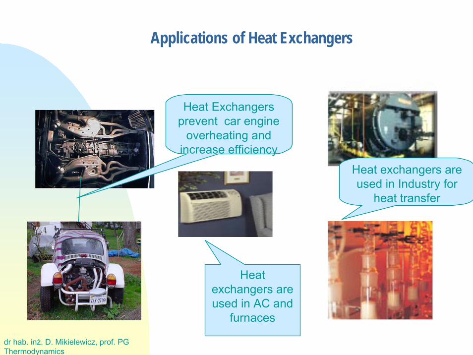
Applications of Heat Exchangers
Heat Exchangersprevent car engine
overheating andincrease efficiency
Heat exchangers areused in Industry for
heat transfer
Heatexchangers areused in AC and
furnaces
dr hab. inż. D. Mikielewicz, prof. PGThermodynamics
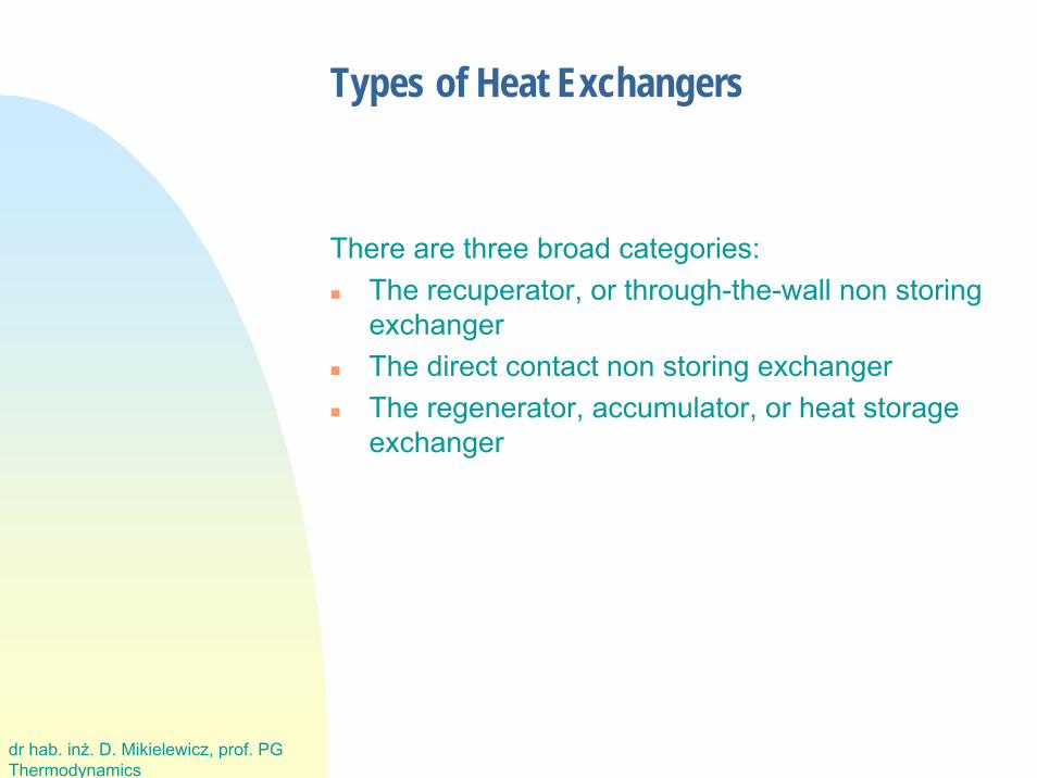
Types of Heat Exchangers
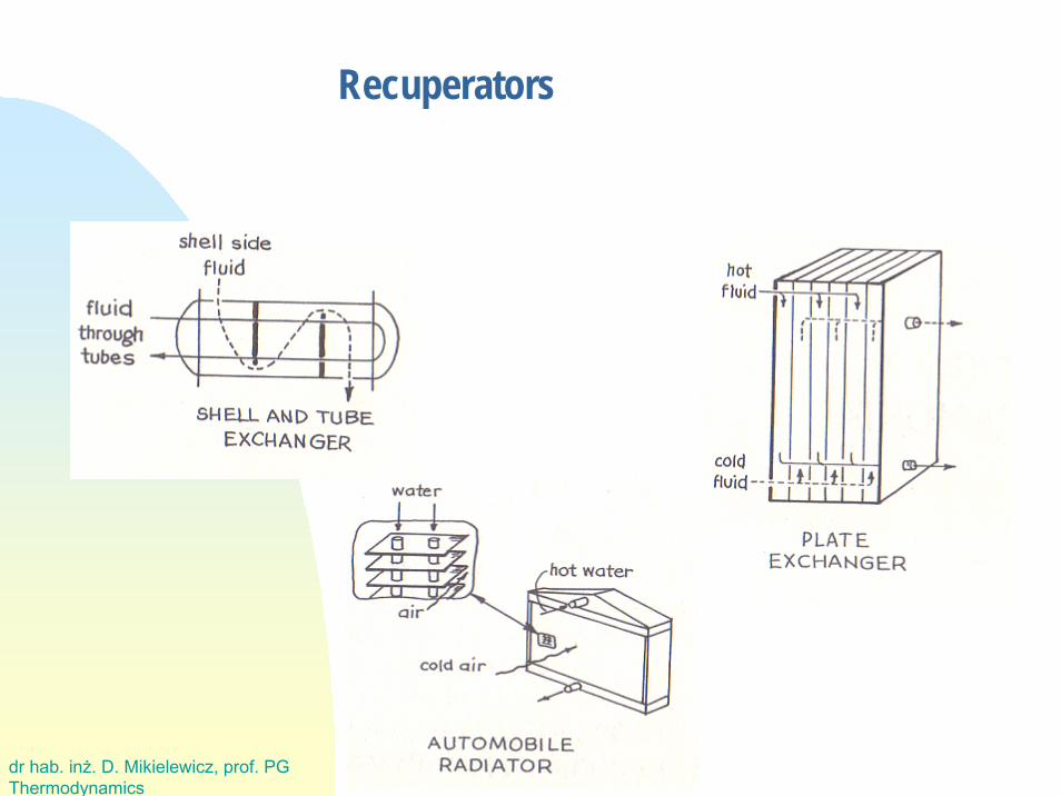
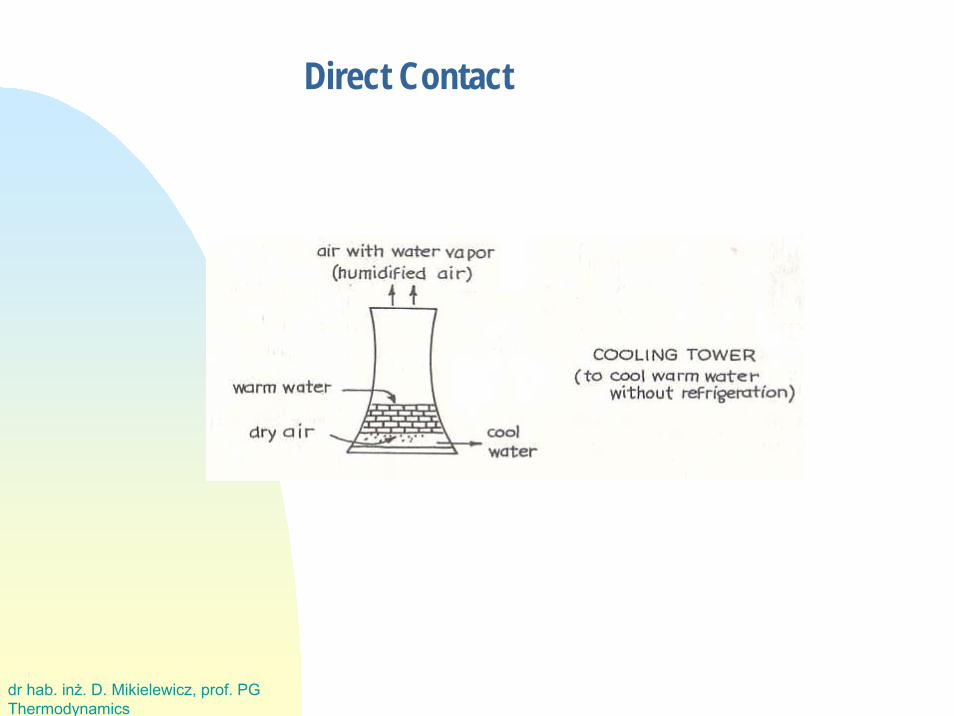
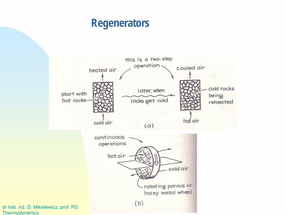
There are three broad categories:The recuperator, or through-the-wall non storingexchangerThe direct contact non storing exchangerThe regenerator, accumulator, or heat storageexchanger
dr hab. inż. D. Mikielewicz, prof. PGThermodynamics
Recuperators
dr hab. inż. D. Mikielewicz, prof. PGThermodynamics
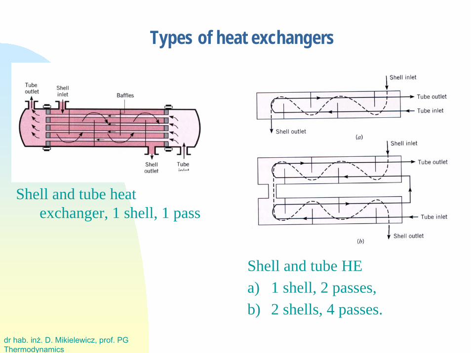
Types of heat exchangers
Shell and tube heatexchanger, 1 shell, 1 pass
Shell and tube HEa) 1 shell, 2 passes, b) 2 shells, 4 passes.
dr hab. inż. D. Mikielewicz, prof. PGThermodynamics
Direct Contact
dr hab. inż. D. Mikielewicz, prof. PGThermodynamics
Regenerators
dr hab. inż. D. Mikielewicz, prof. PGThermodynamics
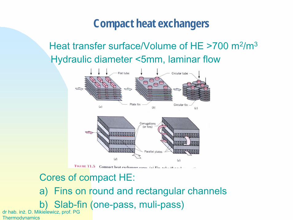
Compact heat exchangers
Heat transfer surface/Volume of HE >700 m2/m3
Hydraulic diameter <5mm, laminar flow
Cores of compact HE:a) Fins on round and rectangular channelsb) Slab-fin (one-pass, muli-pass)
dr hab. inż. D. Mikielewicz, prof. PGThermodynamics
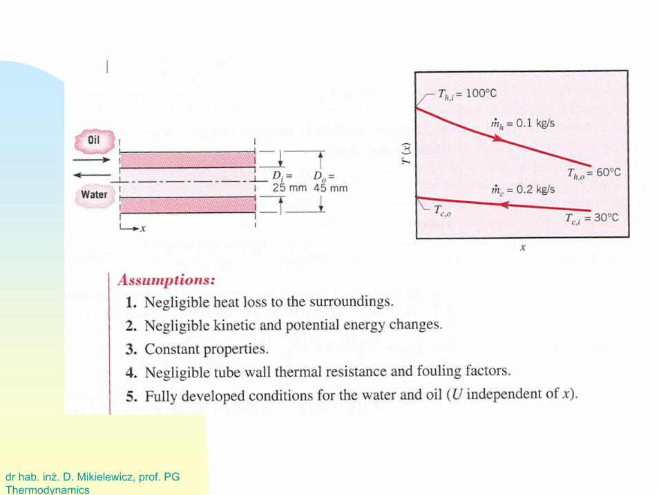
RECUPERATORSHeat transfer in recuperator can take place as steady-stateor transient. Transient heat transfer occurs during thestart-up or shut-down of devices or during the change ofload.
For the possibly simple mathematical description of heattransfer in the recuperator the following assumptions aremade:
· specific heat of both fluids is constant,
· overall heat transfer coefficient k is constant on the entireheat transfer surface,
· no heat losses to surroundings,
heat in the wall is conducted only in the direction normal to the flow.
dr hab. inż. D. Mikielewicz, prof. PGThermodynamics
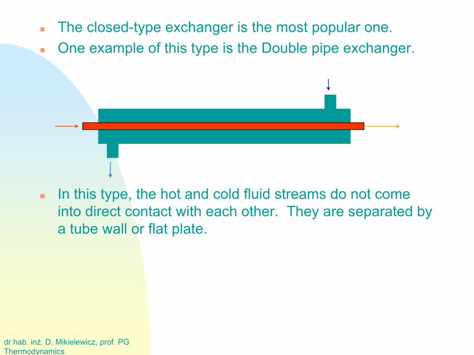
The closed-type exchanger is the most popular one.One example of this type is the Double pipe exchanger.
In this type, the hot and cold fluid streams do not comeinto direct contact with each other. They are separated by a tube wall or flat plate.

dr hab. inż. D. Mikielewicz, prof. PGThermodynamics
Principle of Heat Exchanger
First Law of Thermodynamic: “Energy is conserved.”
generatedsin out
outin ewqhmhmdtdE
&&&&& +++⎟⎠
⎞⎜⎝
⎛−= ∑ ∑ ˆ.ˆ.
∑∑ −=outin
hmhm ˆ.ˆ. &&h
hphh TCmAQ Δ= ... &
ccpcc TCmAQ Δ= ... &
0 0 0 0
•Control Volume
Qh
Cross Section AreaHOT
COLD
Thermal Boundary Layer
Pierwsza strona
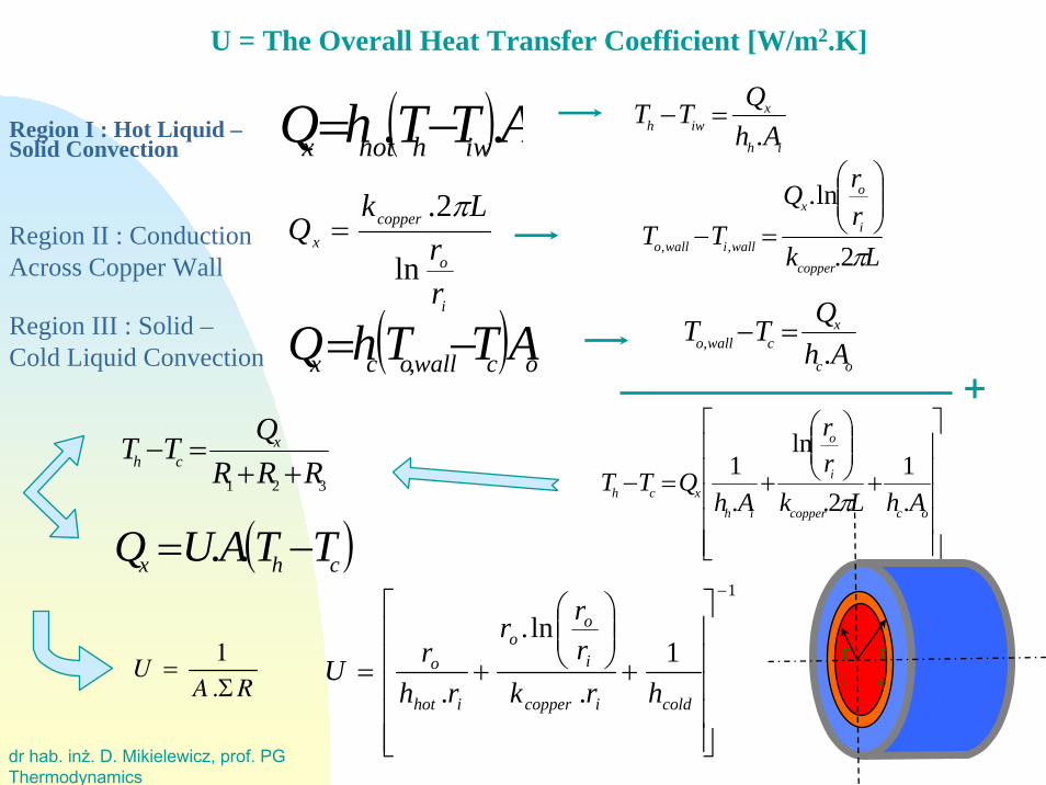
Q hot Q cold
Th Ti,wall
To,wall
Tc
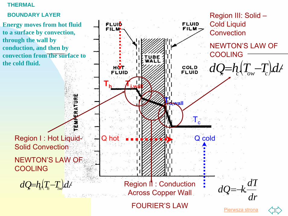
Region I : Hot Liquid-Solid Convection
NEWTON’S LAW OF COOLING
( )dATThdQ iwhhx .. −= Region II : ConductionAcross Copper Wall
FOURIER’S LAWdrdTkdQx .−=
Region III: Solid –Cold LiquidConvection
NEWTON’S LAW OF COOLING
( )dATThdQ cowcx .. −=
THERMAL
BOUNDARY LAYER
Energy moves from hot fluid to a surface by convection, through the wall by conduction, and then by convection from the surface to the cold fluid.
dr hab. inż. D. Mikielewicz, prof. PGThermodynamics
Region I : Hot Liquid –Solid Convection ih
xiwh Ah
QTT.
=−( )ATThQ iwhhotx .. −=
Region II : ConductionAcross Copper Wall
i
o
copperx
rr
LkQ
ln
2. π=
LkrrQ
TTcopper
i
ox
walliwallo π2.
ln.
,,
⎟⎟⎠
⎞⎜⎜⎝
⎛
=−
Region III : Solid –Cold Liquid Convection oc
xcwallo Ah
QTT., =−( ) ocwallocx ATThQ −= ,
+
⎥⎥⎥⎥⎥
⎦
⎤
⎢⎢⎢⎢⎢
⎣
⎡
+⎟⎟⎠
⎞⎜⎜⎝
⎛
+=−occopper
i
o
ihxch AhLk
rr
AhQTT
.1
2.
ln
.1
π
( )chx TTAUQ −= ..1
1.
ln.
.
−
⎥⎥⎥⎥⎥
⎦
⎤
⎢⎢⎢⎢⎢
⎣
⎡
+⎟⎟⎠
⎞⎜⎜⎝
⎛
+=coldicopper
i
oo
ihot
o
hrkrrr
rhrU
U = The Overall Heat Transfer Coefficient [W/m2.K]
321 RRRQTT x
ch ++=−
U =1
A .ΣR
ro
ri
dr hab. inż. D. Mikielewicz, prof. PGThermodynamics
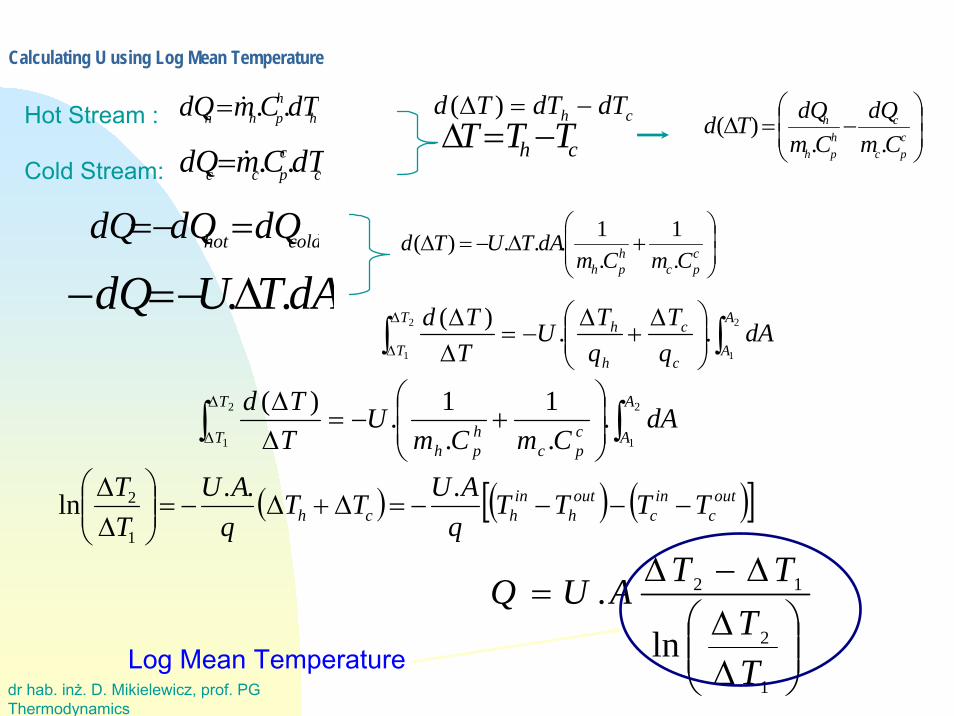
Calculating U using Log Mean Temperature
coldhot dQdQdQ =−=
ch TTT −=Δch dTdTTd −=Δ )(h
hphh dTCmdQ ..&=
ccpcc dTCmdQ ..&=
Hot Stream :
Cold Stream:⎟⎟⎠
⎞⎜⎜⎝
⎛−=Δ
cpc
chph
h
CmdQ
CmdQTd
..)(
dATUdQ ..Δ−=−⎟⎟⎠
⎞⎜⎜⎝
⎛+Δ−=Δ c
pchph CmCm
dATUTd.1
.1...)(
∫∫ ⎟⎟⎠
⎞⎜⎜⎝
⎛+−=
ΔΔΔ
Δ
2
1
2
1
..1
.1.)( A
Acpc
hph
T
TdA
CmCmU
TTd
( ) ( ) ( )[ ]outc
inc
outh
inhch TTTT
qAUTT
qAU
TT
−−−−=Δ+Δ−=⎟⎟⎠
⎞⎜⎜⎝
⎛ΔΔ ...ln
1
2
∫∫ ⎟⎟⎠
⎞⎜⎜⎝
⎛ Δ+
Δ−=
ΔΔΔ
Δ
2
1
2
1
..)( A
Ac
c
h
hT
TdA
qT
qTU
TTd
⎟⎟⎠
⎞⎜⎜⎝
⎛ΔΔΔ−Δ
=
1
2
12
ln.
TT
TTAUQ
Log Mean Temperature
dr hab. inż. D. Mikielewicz, prof. PGThermodynamics
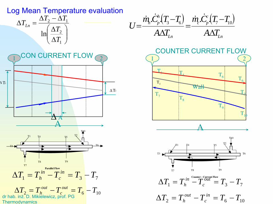
CON CURRENT FLOW
⎟⎟⎠
⎞⎜⎜⎝
⎛ΔΔΔ−Δ
=Δ
1
2
12
lnTT
TTTLn
731 TTTTT inc
inh −=−=Δ
1062 TTTTT outc
outh −=−=Δ
COUNTER CURRENT FLOW
1062 TTTTT inc
outh −=−=Δ
731 TTTTT outc
inh −=−=Δ
( ) ( )Ln
cpc
Ln
hph
TATTCm
TATTCm
UΔ−
=Δ
−=
...
... 10763
&&&&
T1T2
T4 T5
T3
T7 T8 T9
T10
T6
Counter - Current Flow
T1 T2T4 T5
T6T3
T7T8 T9
T10
Parallel Flow
Log Mean Temperature evaluation
T1
A
1 2
T2
T3
T6
T4 T6
T7 T8
T9
T10
WallΔT1
ΔT2
Δ AA
1 2
dr hab. inż. D. Mikielewicz, prof. PGThermodynamics
T1
A
1 2
T2
T3
T6
T4 T6
T7 T8
T9
T10
Wall
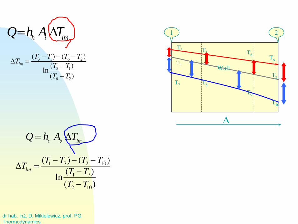
lmih TAhQ Δ=
ΔTlm =(T3 −T1) − (T6 −T2)
ln(T3 −T1)(T6 −T2)
lmoc TAhQ Δ=
ΔTlm =(T1 −T7) − (T2 −T10)
ln(T1 −T7)(T2 −T10)
dr hab. inż. D. Mikielewicz, prof. PGThermodynamics
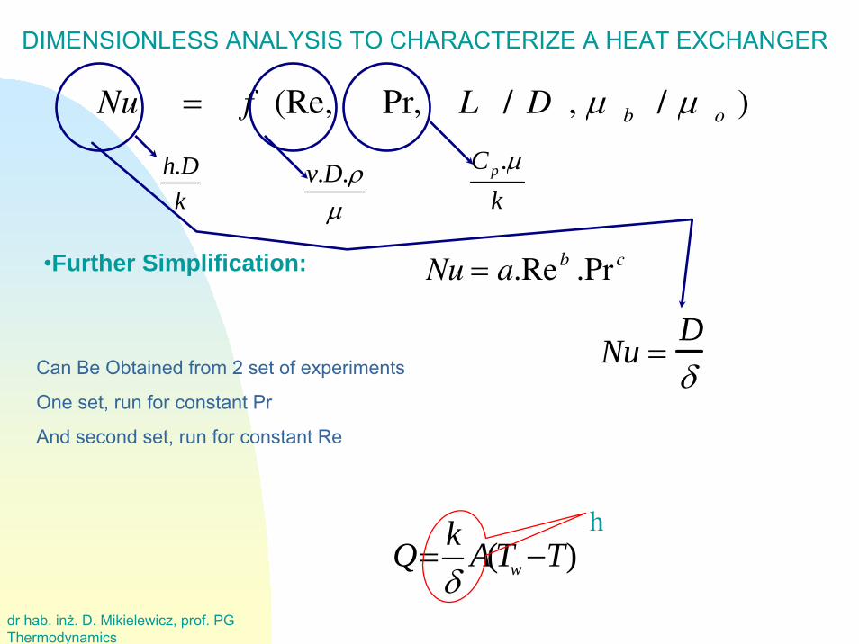
Nu = f (Re, Pr, L / D , μ b / μ o )
DIMENSIONLESS ANALYSIS TO CHARACTERIZE A HEAT EXCHANGER
μρ..Dv
kCp μ.
kDh.
Nu = a.Reb .Pr c•Further Simplification:
Can Be Obtained from 2 set of experiments
One set, run for constant Pr
And second set, run for constant Re
)( TTAkQ w −=δ
h
Nu =Dδ
dr hab. inż. D. Mikielewicz, prof. PGThermodynamics
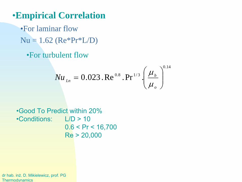
•For laminar flowNu = 1.62 (Re*Pr*L/D)
•Empirical Correlation
14.0
3/18.0 .Pr.Re.023.0 ⎟⎟⎠
⎞⎜⎜⎝
⎛=
o
bLnNu
μμ
•For turbulent flow
•Good To Predict within 20%•Conditions: L/D > 10
0.6 < Pr < 16,700Re > 20,000
dr hab. inż. D. Mikielewicz, prof. PGThermodynamics
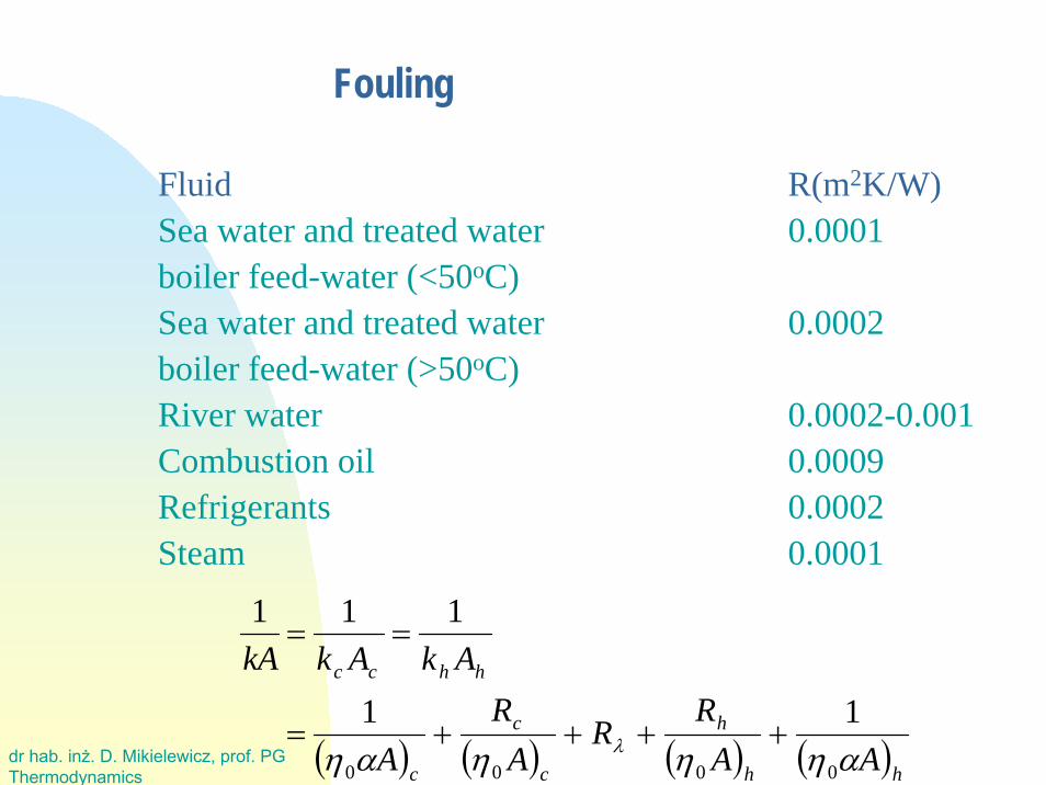
Fouling
( ) ( ) ( ) ( )hh
h
c
c
c
hhcc
AAR
RA
RA
AkAkkA
αηηηαη λ0000
11
111
++++=
==
Fluid R(m2K/W)Sea water and treated water 0.0001boiler feed-water (<50oC)Sea water and treated water 0.0002boiler feed-water (>50oC)River water 0.0002-0.001Combustion oil 0.0009Refrigerants 0.0002Steam 0.0001

dr hab. inż. D. Mikielewicz, prof. PGThermodynamics
Overall heat transfer coefficient
( ) ( )( )
( ) ( )oo
oio
i
i
i
ooii
AAR
Ldd
AR
A
AkAkkA
απλα1
2/ln1
111
++++=
==
Fluid-combination k(m2K/W)Water-water 850-1700Water-oil 110-350Steam condenser (water in tubes) 1000-6000Ammonia condenser (water in tubes) 800-1400 Alcohol condenser (water in tubes) 250-700 Finned tubes (water in tubes,air cross-flow) 25-50
dr hab. inż. D. Mikielewicz, prof. PGThermodynamics
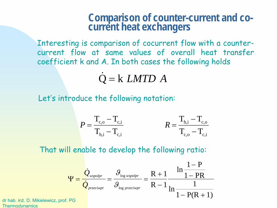
Comparison of counter-current and co-current heat exchangers
Interesting is comparison of cocurrent flow with a counter-current flow at same values of overall heat transfer coefficient k and A. In both cases the following holds
ALMTDkQ =&
Let’s introduce the following notation:
ic,oc,
oc,ih,
ic,ih,
ic,oc,
TTTT
TTTT
−−
=−−
= RP
Ψ = = =+−
−−
− +
&
&log
log
wspolpr
przeciwpr
wspolpr
przeciwpr
ϑϑ
R 1R 1
ln1 P
1 PR
ln1
1 P(R 1)
That will enable to develop the following ratio:

dr hab. inż. D. Mikielewicz, prof. PGThermodynamics
It results from the figure that the thermal load of co-currentrecuperator is lower than thermal load of counter-currentrecuperator. Only in case of values R=0 or P=0 these loads are same.
Such conditions corresponds to the constant temperature of one offluids (its phase change). The counter-current is always better thatco-current from the point of view of used heat transfer surface.
In other words in case of counter-current the fluid can be heated to a higher temperature than in case of co-current flow.
Comparison of counter-current and co-current heat exchangers
dr hab. inż. D. Mikielewicz, prof. PGThermodynamics
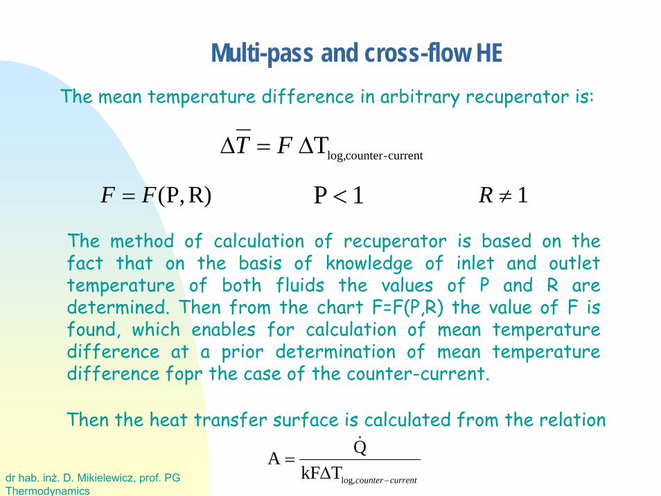
Multi-pass and cross-flow HEThe mean temperature difference in arbitrary recuperator is:
current-counterlog,TΔ=Δ FT
The method of calculation of recuperator is based on thefact that on the basis of knowledge of inlet and outlettemperature of both fluids the values of P and R aredetermined. Then from the chart F=F(P,R) the value of F isfound, which enables for calculation of mean temperaturedifference at a prior determination of mean temperaturedifference fopr the case of the counter-current.
R)P,(FF = P 1< R ≠ 1
currentcounter−Δ=
,logTkFQA&
Then the heat transfer surface is calculated from the relation
dr hab. inż. D. Mikielewicz, prof. PGThermodynamics
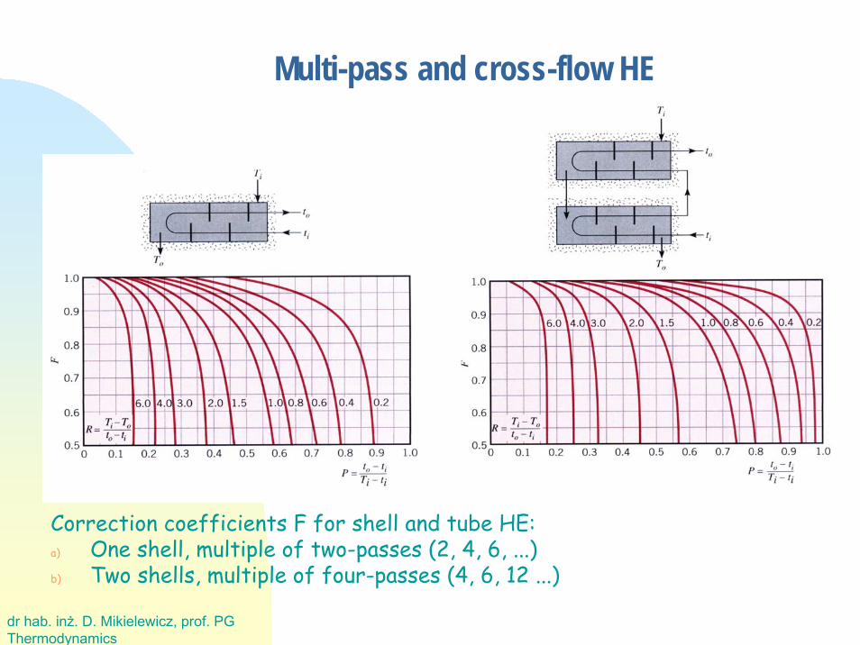
Correction coefficients F for shell and tube HE:a) One shell, multiple of two-passes (2, 4, 6, ...)b) Two shells, multiple of four-passes (4, 6, 12 ...)
Multi-pass and cross-flow HE
dr hab. inż. D. Mikielewicz, prof. PGThermodynamics
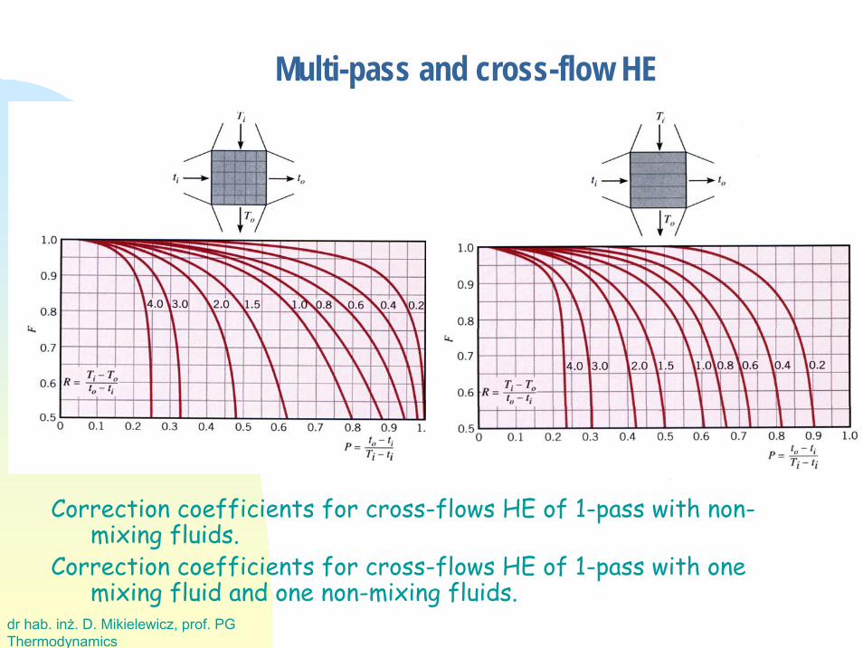
Correction coefficients for cross-flows HE of 1-pass with non-mixing fluids.
Correction coefficients for cross-flows HE of 1-pass with one mixing fluid and one non-mixing fluids.
Multi-pass and cross-flow HE
dr hab. inż. D. Mikielewicz, prof. PGThermodynamics
Design procedure
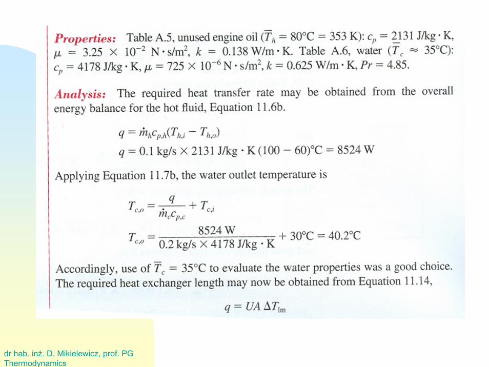
1. Formulation of thermal balance
• one temperature can be determined from here
• the rate of heat in HE can be determined
2. Selection of flow orientation, approximate distribution of temperatures and calculationof logarithmic mean temperature difference
3. Initial assumption of the heating surface (diameter of tubes) and flow of fluid aroundthem
• inside tubes should be the more aggressive fluid, giving fouling with high pressure
• on external side of tubes is the flow with higher viscosity, with smaller pressure drop
• external diameter from the range: 10 … 15… 25 … 40 mm
• wall thickness from the range 0 … 2.5 mm (due to strength of material)
• assumption of the spatial pitch, i.e. parallel, hexagonal (highest packing), concentric,
• assumption of the ratio s/dz
dr hab. inż. D. Mikielewicz, prof. PGThermodynamics
Design procedure
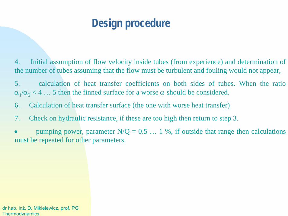
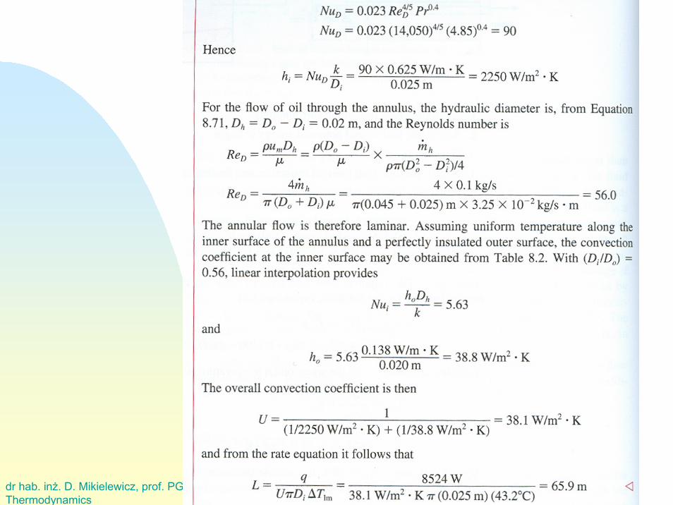
4. Initial assumption of flow velocity inside tubes (from experience) and determination ofthe number of tubes assuming that the flow must be turbulent and fouling would not appear,
5. calculation of heat transfer coefficients on both sides of tubes. When the ratioα1/α2 < 4 … 5 then the finned surface for a worse α should be considered.
6. Calculation of heat transfer surface (the one with worse heat transfer)
7. Check on hydraulic resistance, if these are too high then return to step 3.
• pumping power, parameter N/Q = 0.5 … 1 %, if outside that range then calculationsmust be repeated for other parameters.
dr hab. inż. D. Mikielewicz, prof. PGThermodynamics
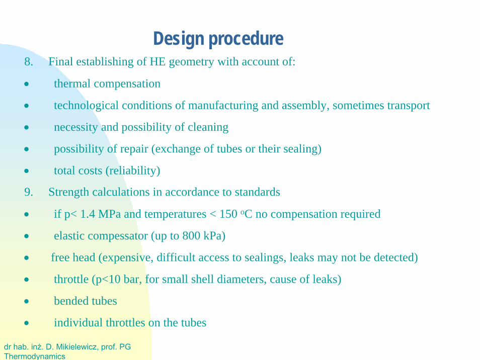
Design procedure8. Final establishing of HE geometry with account of:
• thermal compensation
• technological conditions of manufacturing and assembly, sometimes transport
• necessity and possibility of cleaning
• possibility of repair (exchange of tubes or their sealing)
• total costs (reliability)
9. Strength calculations in accordance to standards
• if p< 1.4 MPa and temperatures < 150 oC no compensation required
• elastic compessator (up to 800 kPa)
• free head (expensive, difficult access to sealings, leaks may not be detected)
• throttle (p<10 bar, for small shell diameters, cause of leaks)
• bended tubes
• individual throttles on the tubes
dr hab. inż. D. Mikielewicz, prof. PGThermodynamics
Design procedure
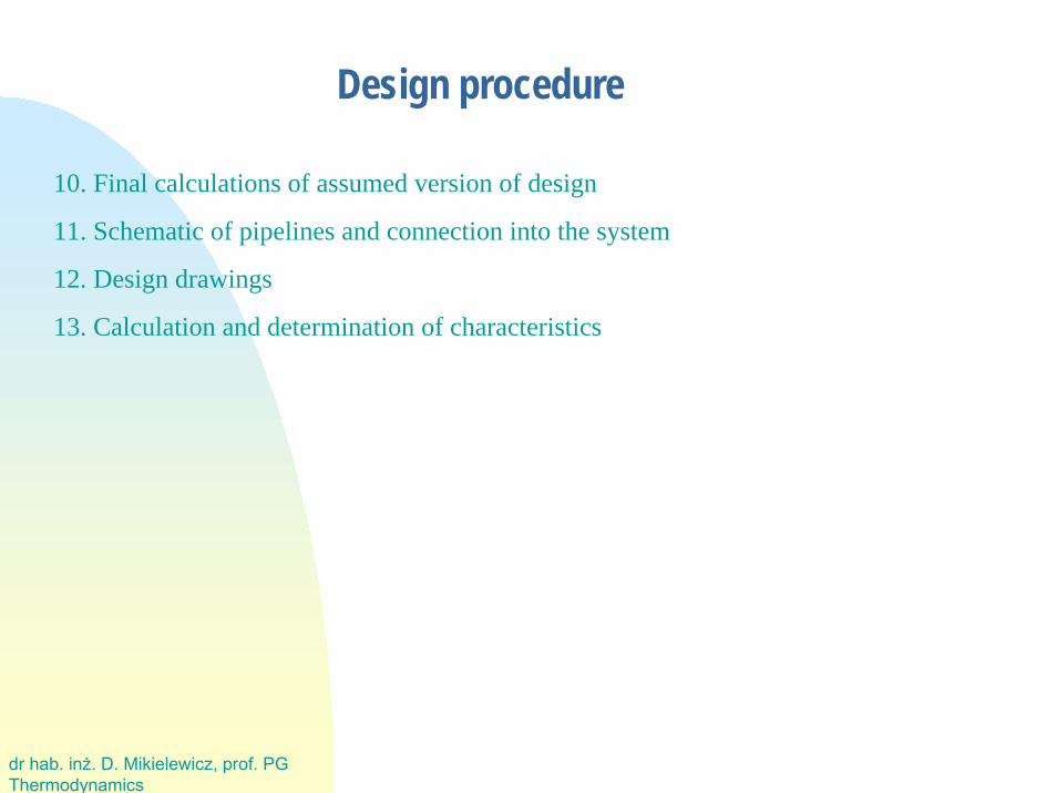
10. Final calculations of assumed version of design
11. Schematic of pipelines and connection into the system
12. Design drawings
13. Calculation and determination of characteristics
dr hab. inż. D. Mikielewicz, prof. PGThermodynamics
dr hab. inż. D. Mikielewicz, prof. PGThermodynamics
dr hab. inż. D. Mikielewicz, prof. PGThermodynamics
dr hab. inż. D. Mikielewicz, prof. PGThermodynamics