Embed Size (px)
Citation preview

PSR/PSV/PSK Series
Hybrid Stepper Drive
Datasheet
Version HSD‐2016‐01
http://www.PrimoPal.com

PSR/PSV/PSK Series Hybrid Stepper Drives
PrimoPal Motor ∙ No. 188 Zhangyang Road, Shanghai 200120, China ∙ Tel +86 21 5018 7836 ∙ Fax +86 21 5017 9351 ∙ www.primopal.com ∙ [email protected] 1
Description
PrimoPal provides three types of stepper drives, including PSR series, PSV series and PSK series. The PSR series of
analog stepper drives adopt precise analog current control and are characterized by superior high‐speed torque,
relatively low stepping noise and low motor heating. The PSV series of voltage control stepper drives adjust the
velocity via the external potentiometer or analog 0‐5V input, which could ideally replace the brushless motor with
gearbox due to its high torque and less motor noise at low speed. The PSK series of digital stepper drives are
DSP‐based innovative products. Their features include super‐low stepping noise, anti‐resonance, low‐speed ripple
smoothing and low motor heating.
Applications
PrimoPal’s PSR/PSV/PSK series stepper drives are suitable for driving a wide range of stepper motors, from frame
size NEMA 8 to NEMA 42. Typical applications include CNC routers, laser cutters, laser markers, medical equipment,
X‐Y tables, measurement equipment, 3D printers, and many other industrial and office automation applications.
Part Number
PrimoPal’s Stepper Drives Summary
Model Phase Output Current
Operating Voltage
Microstep Resolutions
Driving Motors
Size Weight
A AC DC NEMA mm Kg
PSR Series:
PSR3015 2 0.2‐1.5 N/A 10‐30 1‐16 8‐17 68.5×59×27.5 0.06
PSR4015 2 0.21‐1.5 N/A 18‐40 1‐64 8‐17 86×55×20 0.10
PSR4020 2 0.25‐2.0 N/A 18‐40 1‐128 8‐17 86×55×20 0.10
PSR5042 2 1.0‐4.2 N/A 18‐50 2‐128, 5‐125 17‐24 118×75.5×34 0.28
PSR8078 2 2.8‐7.8 N/A 24‐80 2‐256, 5‐250 34‐42 139×97×48 0.55
PSR8078AC 2 2.8‐7.8 18‐80 24‐110 2‐256, 5‐250 34‐42 139×97×48 0.55
PSV Series:
PSV3015 2 0.2‐1.5 N/A 10‐30 16 8‐17 68.5×59×27.5 0.06
PSK Series:
PSK5045 2 1.0‐4.5 N/A 20‐50 1‐128, 5‐125 17‐24 118×71×27 0.24
Max. Output Current15: 1.5A 42: 4.2A ……
No. of Phase Blank: 2‐phase3PH: 3‐phase 5PH: 5‐phase
Max. Input Voltage 30: 30VDC 40: 40VDC ……
Driver Type PSR: PSR Series PSV: PSV Series PSK: PSK Series
Voltage Type:Blank: DC Power AC: AC power
Prim
oPal
PSR/PSV
/PSK se
ries
Hybrid
Stepper D
rives PSR
Series PSV
Series PSK
Series

PSR/PSV/PSK Series Hybrid Stepper Drives
PrimoPal Motor ∙ No. 188 Zhangyang Road, Shanghai 200120, China ∙ Tel +86 21 5018 7836 ∙ Fax +86 21 5017 9351 ∙ www.primopal.com ∙ [email protected] 2
General Specifications
Heat Sinking Method Natural cooling or forced cooling
Operating
Environment
Environment No corrosive gas, dust, water or oil
Ambient Temperature 0 to +50 °C (+32 to +122 °F) (non‐freezing)
Humidity 90% or less (non‐condensing)
Operating Temperature 70°C Max
Vibration 5.9m/s2 Max
Storage Temperature ‐10 to +70 °C (+14 to +158 °F) (non‐freezing)
Control Signal Connections (PSR Series)
Series connect resistors for current‐limiting when +12V or +24V used. R=1K (>0.25W) if VCC=12V; R=2K (>0.25W) if VCC=24V.
Make sure that the current through the opto‐coupler is between 7 mA and 16 mA.
Typical Connections (PSR Series)
Prim
oPal
PSR/PSV
/PSK se
ries
Hybrid
Stepper D
rives PSR
Series PSV
Series PSK
Series

PSR3015 PSR Series Stepper Drives
PrimoPal Motor ∙ No. 188 Zhangyang Road, Shanghai 200120, China ∙ Tel +86 21 5018 7836 ∙ Fax +86 21 5017 9351 ∙ www.primopal.com ∙ [email protected] 3
█ Introduction The stepper drive PSR3015 is a very small size high performance microstepping drive based on one of the most advanced technologies in the world today. It’s suitable for driving small and medium 2‐phase and 4‐phase hybrid stepping motors. By using advanced bipolar constant‐current chopping technique, it can output higher speed and more power from the same motor, compared with traditional drives such as L/R drives.
The stepper drive PSR3015 is suitable for a wide range of stepping motors from NEMA size 8 to 17, which are used in various kinds of machines, such as 3D printers, X‐Y tables, labeling machines, laser cutters, engraving machines, pick‐place devices, and etc.
█ Electrical Specifications Parameters Min Typical Max Unit
Output current 0.2 ‐ 1.5 (1.06RMS) A
Supply voltage +10 +24 +30 VDC
Logic signal current 7 10 16 mA
Pulse input frequency 0 ‐ 200 kHz
Isolation resistance 500 MΩ
█ Function Description
Function Description
Microstep Setting 5 selectable microstep resolutions up to 3,200 steps/rev. Set by SW1, 2, 3 of the DIP switch.
Current Setting The potentiometer pointer is used to set the operating current, which is up to 1.5 A.
Automatic Standstill Current Reduction
The current will be automatically reduced to 50% of the selected operating current 0.4 second after the last pulse.
Control Signals PUL+ and PUL‐ are for the pulse command signal. DIR+ and DIR‐ are for the direction control signal. EN+ and EN‐ are for the enable/disable control signal.
Motor Connector A+, A‐ and B+, B‐ are for motor connections. Exchanging the connection of two wires for a coil to the drive will reversedefault motion direction.
Power Connector Recommended to use power supplies with output of +12 to 24VDC, leaving space for power fluctuation and back‐EMF.
Indicators There are two LED indicators on the drive for power and alarm signals. When the Green LED is on, the drive is powered up. When the Red LED is on, the drive is in fault status. When in fault status, the motor shaft will be free. Reset the drive by re‐powering it to make it function properly after solving problem(s).
█ Parameter Settings This drive PSR3015 uses a circular potentiometer pointer and a 4‐bit DIP switch to set motor operating current, microstep resolution and pulse mode, as shown below:
█ Mechanical Dimension
█ Operating Current Settings Peak Current RMS Current Position
0.20A 0.14A 1
0.40A 0.28A 2
0.60A 0.42A 3
0.75A 0.53A 4
0.87A 0.62A 5
1.07A 0.76A 6
1.12A 0.79A 7
1.29A 0.91A 8
1.50A 1.06A 9
█ Microstep Resolution Settings Microstep Steps/Rev. SW1 SW2 SW3
1 200 ON ON ON
2 400 OFF ON ON
4 800 ON OFF ON
8 1,600 OFF OFF ON
16 3,200 ON ON OFF
█ Pulse Mode Settings
SW4 Pulse Mode
ON PUL + DIR
OFF CW + CCW
Pulse Mode Microstep Setting Operating Current Setting
Prim
oPal
PSR
series
Hybrid
Stepper D
rives PSR3015
PSR4015
PSR4020
PSR5042
PSR8078
PSR8078AC
PSV
series
Hybrid
Stepper D
rives
PSK
series
Hybrid
Stepper D
rives

PSR4015 PSR Series Stepper Drives
PrimoPal Motor ∙ No. 188 Zhangyang Road, Shanghai 200120, China ∙ Tel +86 21 5018 7836 ∙ Fax +86 21 5017 9351 ∙ www.primopal.com ∙ [email protected] 4
█ Introduction The stepper drive PSR4015 is a very small size high performance microstepping driver based on one of the most advanced technologies in the world today. It’s suitable for driving small and medium 2‐phase and 4‐phase hybrid stepping motors. By using advanced bipolar constant‐current chopping technique, it can output more speed and power from the same motor, compared with traditional drivers such as L/R drivers.
The stepper drive PSR4015 is suitable for a wide range of stepping motors from NEMA size 8 to 17, which used in various kinds of machines, such as X‐Y tables, labeling machines, laser cutters, engraving machines, pick‐place devices, and etc. It’s specially adapted to the applications desired with low vibration, high speed and high precision.
█ Electrical Specifications
Parameters Min Typical Max Unit
Output current 0.21 ‐ 1.5 (1.07 RMS) A
Supply voltage +18 +24 +40 VDC
Logic signal current 7 10 16 mA
Pulse input frequency 0 ‐ 100 kHz
Isolation resistance 500 MΩ
█ Function Description
Function Description
Microstep Setting 7 selectable microstep resolutions up to 12,800 steps/rev. Set by SW4, 5, 6 of the DIP switch.
Current Setting The first three bits (SW1, 2, 3) of the DIP switch are used to set the operating current, which is up to 1.5 A.
Control Signals PUL is for the pulse command signal. DIR is for the direction control signal. ENA is for the enable/disable control signal. Series connect resistors for current‐limiting when +12V or +24V is used.
Motor Connector A+, A‐ and B+, B‐ are for motor connections. Exchanging the connection of two wires for a coil to the drive will reversedefault motion direction.
Power Connector Recommended to use power supplies with theoretical output of +18 to +36VDC, leaving space for power fluctuation and back‐EMF.
Indicators There are two LED indicators on the drive for power and alarm signals. When the Green LED is on, the drive is powered up. When the Red LED is on, the drive is in fault status. When in fault status, the motor shaft will be free. Reset the drive by re‐powering it to make it function properly after solving problem(s).
█ Parameter Settings This drive PSR4015 uses a 6‐bit DIP switch to set microstep resolution and motor operating current, as shown below:
█ Mechanical Dimension
█ Operating Current Settings Peak Current RMS Current SW1 SW2 SW3
0.21A 0.15A OFF ON ON
0.42A 0.30A ON OFF ON
0.63A 0.45A OFF OFF ON
0.84A 0.60A ON ON OFF
1.05A 0.75A OFF ON OFF
1.26A 0.90A ON OFF OFF
1.50A 1.07A OFF OFF OFF
█ Microstep Resolution Settings Microstep Steps/Rev. SW4 SW5 SW6
1 200 ON ON ON
2 400 OFF ON ON
4 800 ON OFF ON
8 1,600 OFF OFF ON
16 3,200 ON ON OFF
32 6,400 OFF ON OFF
64 12,800 ON OFF OFF
P
rimoP
al PSR
series
Hybrid
Stepper D
rives PSR3015
PSR4015
PSR4020
PSR5042
PSR8078
PSR8078AC
PSV
series
Hybrid
Stepper D
rives
PSK
series
Hybrid
Stepper D
rives
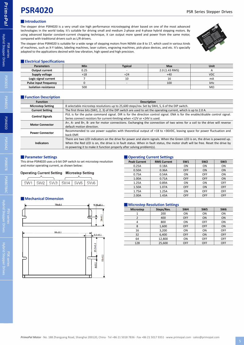
PSR4020 PSR Series Stepper Drives
PrimoPal Motor ∙ No. 188 Zhangyang Road, Shanghai 200120, China ∙ Tel +86 21 5018 7836 ∙ Fax +86 21 5017 9351 ∙ www.primopal.com ∙ [email protected] 5
█ Introduction The stepper drive PSR4020 is a very small size high performance microstepping driver based on one of the most advanced technologies in the world today. It’s suitable for driving small and medium 2‐phase and 4‐phase hybrid stepping motors. By using advanced bipolar constant‐current chopping technique, it can output more speed and power from the same motor, compared with traditional drivers such as L/R drivers.
The stepper drive PSR4020 is suitable for a wide range of stepping motors from NEMA size 8 to 17, which used in various kinds of machines, such as X‐Y tables, labeling machines, laser cutters, engraving machines, pick‐place devices, and etc. It’s specially adapted to the applications desired with low vibration, high speed and high precision.
█ Electrical Specifications
Parameters Min Typical Max Unit
Output current 0.25 ‐ 2.0 (1.43 RMS) A
Supply voltage +18 +24 +40 VDC
Logic signal current 7 10 16 mA
Pulse input frequency 0 ‐ 100 kHz
Isolation resistance 500 MΩ
█ Function Description
Function Description
Microstep Setting 8 selectable microstep resolutions up to 25,600 steps/rev. Set by SW4, 5, 6 of the DIP switch.
Current Setting The first three bits (SW1, 2, 3) of the DIP switch are used to set the operating current, which is up to 2.0 A.
Control Signals PUL is for the pulse command signal. DIR is for the direction control signal. ENA is for the enable/disable control signal. Series connect resistors for current‐limiting when +12V or +24V is used.
Motor Connector A+, A‐ and B+, B‐ are for motor connections. Exchanging the connection of two wires for a coil to the drive will reversedefault motion direction.
Power Connector Recommended to use power supplies with theoretical output of +18 to +36VDC, leaving space for power fluctuation and back‐EMF.
Indicators There are two LED indicators on the drive for power and alarm signals. When the Green LED is on, the drive is powered up. When the Red LED is on, the drive is in fault status. When in fault status, the motor shaft will be free. Reset the drive by re‐powering it to make it function properly after solving problem(s).
█ Parameter Settings This drive PSR4020 uses a 6‐bit DIP switch to set microstep resolution and motor operating current, as shown below:
█ Mechanical Dimension
█ Operating Current Settings Peak Current RMS Current SW1 SW2 SW3
0.25A 0.18A ON ON ON
0.50A 0.36A OFF ON ON
0.75A 0.54A ON OFF ON
1.00A 0.71A OFF OFF ON
1.25A 0.89A ON ON OFF
1.50A 1.07A OFF ON OFF
1.75A 1.25A ON OFF OFF
2.00A 1.43A OFF OFF OFF
█ Microstep Resolution Settings Microstep Steps/Rev. SW4 SW5 SW6
1 200 ON ON ON
2 400 OFF ON ON
4 800 ON OFF ON
8 1,600 OFF OFF ON
16 3,200 ON ON OFF
32 6,400 OFF ON OFF
64 12,800 ON OFF OFF
128 25,600 OFF OFF OFF
Prim
oPal
PSR
series
Hybrid
Stepper D
rives PSR3015
PSR4015
PSR4020
PSR5042
PSR8078
PSR8078AC
PSV
series
Hybrid
Stepper D
rives
PSK
series
Hybrid
Stepper D
rives

PSR5042 PSR Series Stepper Drives
PrimoPal Motor ∙ No. 188 Zhangyang Road, Shanghai 200120, China ∙ Tel +86 21 5018 7836 ∙ Fax +86 21 5017 9351 ∙ www.primopal.com ∙ [email protected] 6
█ Introduction The stepper drive PSR5042 is a high performance microstepping driver based on pure‐sinusoidal current control technology. Owing to the advanced technology, it could output smaller noise, lower heating, smoother movement and have better performances at higher speed than most of the drivers in the markets.
The stepper drive PSR5042 is suitable for a wide range of stepping motors, from NEMA size 17 to 24. It can be used in various kinds of machines, such as X‐Y tables, engraving machines, labeling machines, laser cutters, pick‐place devices, and so on. Particularly adapt to the applications desired with low noise, low heating, high speed and high precision.
█ Electrical Specifications
Parameters Min Typical Max Unit
Output current 1.0 ‐ 4.2 (3.0 RMS) A
Supply voltage +18 +36 +50 VDC
Logic signal current 7 10 16 mA
Pulse input frequency 0 ‐ 300 kHz
Isolation resistance 500 MΩ
█ Function Description
Function Description
Microstep Setting 15 selectable microstep resolutions up to 25,600 steps/rev. Set by SW5, 6, 7, 8 of the DIP switch.
Current Setting The first three bits (SW1, 2, 3) of the DIP switch are used to set the operating current, which is up to 4.2 A.
Automatic Standstill Current Reduction
SW4 is used for the automatic standstill current reduction function. When this function is active, the current will be automatically reduced to 50% of the selected operating current 0.4 second after the last pulse. Theoretically, this will reduce motor heating to 25% (due to P=I
2*R) of the original value.
Control Signals PUL+ and PUL‐ are for the pulse command signal. DIR+ and DIR‐ are for the direction control signal. ENA+ and ENA‐ are for the enable/disable control signal. Series connect resistors for current‐limiting when +12V or +24V is used.
Motor Connector A+, A‐ and B+, B‐ are for motor connections. Exchanging the connection of two wires for a coil to the drive will reversedefault motion direction.
Power Connector Recommended to use power supplies with theoretical output of +20 to 45VDC, leaving space for power fluctuation and back‐EMF.
Indicators There are two LED indicators on the drive for power and alarm signals. When the Green LED is on, the drive is powered up. When the Red LED is on, the drive is in fault status. When in fault status, the motor shaft will be free. Reset the drive by re‐powering it to make it function properly after solving problem(s).
█ Parameter Settings This drive PSR5042 uses a 8‐bit DIP switch to set microstep resolution and motor operating current, as shown below:
█ Mechanical Dimension
█ Operating Current Settings Peak Current RMS Current SW1 SW2 SW3
1.00A 0.71A ON ON ON
1.46A 1.04A OFF ON ON
1.92A 1.36A ON OFF ON
2.37A 1.69A OFF OFF ON
2.84A 2.03A ON ON OFF
3.32A 2.36A OFF ON OFF
3.76A 2.69A ON OFF OFF
4.20A 3.00A OFF OFF OFF
█ Microstep Resolution Settings Microstep Steps/Rev. SW5 SW6 SW7 SW8
2 400 OFF ON ON ON
4 800 ON OFF ON ON
8 1,600 OFF OFF ON ON
16 3,200 ON ON OFF ON
32 6,400 OFF ON OFF ON
64 12,800 ON OFF OFF ON
128 25,600 OFF OFF OFF ON
5 1,000 ON ON ON OFF
10 2,000 OFF ON ON OFF
20 4,000 ON OFF ON OFF
25 5,000 OFF OFF ON OFF
40 8,000 ON ON OFF OFF
50 10,000 OFF ON OFF OFF
100 20,000 ON OFF OFF OFF
125 25,000 OFF OFF OFF OFF
Prim
oPal
PSR
series
Hybrid
Stepper D
rives PSR3015
PSR4015
PSR4020
PSR5042
PSR8078
PSR8078AC
PSV
series
Hybrid
Stepper D
rives
PSK
series
Hybrid
Stepper D
rives

PSR8078 PSR Series Stepper Drives
PrimoPal Motor ∙ No. 188 Zhangyang Road, Shanghai 200120, China ∙ Tel +86 21 5018 7836 ∙ Fax +86 21 5017 9351 ∙ www.primopal.com ∙ [email protected] 7
█ Introduction The stepper drive PSR8078 is a high performance microstepping driver based on pure‐sinusoidal current control technology. Owing to the advanced technology, it could output smaller noise, lower heating, smoother movement and have better performances at higher speed than most of the drivers in the markets.
The stepper drive PSR8078 is suitable for a wide range of stepping motors from NEMA 34 to NEMA 42, which is widely used in various kinds of machines, such as CNC routers, cutting machines, packing devices, pick‐place devices, and so on. Particularly suitable for the applications require low cost, low noise, low heating and high speed performance.
█ Electrical Specifications
Parameters Min Typical Max Unit
Output current 2.8 ‐ 7.8 (5.6 RMS) A
Supply voltage +24 +60 +80 VDC
Logic signal current 7 10 16 mA
Pulse input frequency 0 ‐ 300 kHz
Isolation resistance 500 MΩ
█ Function Description
Function Description
Microstep Setting 14 selectable microstep resolutions up to 51,200 steps/rev. Set by SW5, 6, 7, 8 of the DIP switch.
Current Setting The first three bits (SW1, 2, 3) of the DIP switch are used to set the operating current, which is up to 7.8 A.
Automatic Standstill Current Reduction
SW4 is used for the automatic standstill current reduction function. When this function is active, the current will be automatically reduced to 50% of the selected operating current 0.4 second after the last pulse. Theoretically, this will reduce motor heating to 25% (due to P=I
2*R) of the original value.
Control Signals PUL+ and PUL‐ are for the pulse command signal. DIR+ and DIR‐ are for the direction control signal. ENA+ and ENA‐ are for the enable/disable control signal. Series connect resistors for current‐limiting when +12V or +24V is used.
Motor Connector A+, A‐ and B+, B‐ are for motor connections. Exchanging the connection of two wires for a coil to the drive will reversedefault motion direction.
Power Connector Recommended to use power supplies with theoretical output of +24 to +72VDC, leaving space for power fluctuation and back‐EMF.
Indicators There are two LED indicators on the drive for power and alarm signals. When the Green LED is on, the drive is powered up. When the Red LED is on, the drive is in fault status. When in fault status, the motor shaft will be free. Reset the drive by re‐powering it to make it function properly after solving problem(s).
█ Parameter Settings This drive PSR8078 uses a 8‐bit DIP switch to set microstep resolution and motor operating current, as shown below:
█ Mechanical Dimension
█ Operating Current Settings Peak Current RMS Current SW1 SW2 SW3
2.8A 2.0A ON ON ON
3.5A 2.5A OFF ON ON
4.2A 3.0A ON OFF ON
4.9A 3.5A OFF OFF ON
5.7A 4.0A ON ON OFF
6.4A 4.6A OFF ON OFF
7.0A 5.0A ON OFF OFF
7.8A 5.6A OFF OFF OFF
█ Microstep Resolution Settings Microstep Steps/Rev. SW5 SW6 SW7 SW8
2 400 ON ON ON ON
4 800 OFF ON ON ON
8 1,600 ON OFF ON ON
16 3,200 OFF OFF ON ON
32 6,400 ON ON OFF ON
64 12,800 OFF ON OFF ON
128 25,600 ON OFF OFF ON
256 51,200 OFF OFF OFF ON
5 1,000 ON ON ON OFF
10 2,000 OFF ON ON OFF
25 5,000 ON OFF ON OFF
50 10,000 OFF OFF ON OFF
125 25,000 ON ON OFF OFF
250 50,000 OFF ON OFF OFF
Prim
oPal
PSR
series
Hybrid
Stepper D
rives PSR3015
PSR4015
PSR4020
PSR5042
PSR8078
PSR8078AC
PSV
series
Hybrid
Stepper D
rives
PSK
series
Hybrid
Stepper D
rives

PSR8078AC PSR Series Stepper Drives
PrimoPal Motor ∙ No. 188 Zhangyang Road, Shanghai 200120, China ∙ Tel +86 21 5018 7836 ∙ Fax +86 21 5017 9351 ∙ www.primopal.com ∙ [email protected] 8
█ Introduction The stepper drive PSR8078AC is a high performance microstepping driver based on pure‐sinusoidal current control technology. Owing to the above technology and the self‐adjustment technology according to different motors, the driven motors can run with smaller noise, lower heating, smoother movement and have better performances at higher speed than most of the drivers in the markets.
The stepper drive PSR8078AC is suitable for a wide range of stepping motors from NEMA 34 to NEMA 42, which is widely used in various kinds of machines, such as CNC routers, cutting machines, packing devices, pick‐place devices, and so on. Particularly suitable for the applications require low noise, low heating and high speed performance.
█ Electrical Specifications
Parameters Min Typical Max Unit
Output current 2.8 ‐ 7.8 (5.6 RMS) A
Supply voltage 18 48 80 VAC
+24 +72 +110 VDC
Logic signal current 7 10 16 mA
Pulse input frequency 0 ‐ 300 kHz
Isolation resistance 500 MΩ
█ Function Description
Function Description
Microstep Setting 14 selectable microstep resolutions up to 51,200 steps/rev. Set by SW5, 6, 7, 8 of the DIP switch.
Current Setting The first three bits (SW1, 2, 3) of the DIP switch are used to set the operating current, which is up to 7.8 A.
Automatic Standstill Current Reduction
SW4 is used for the automatic standstill current reduction function. When this function is active, the current will be automatically reduced to 50% of the selected operating current 0.4 second after the last pulse. Theoretically, this will reduce motor heating to 25% (due to P=I
2*R) of the original value.
Control Signals PUL+ and PUL‐ are for the pulse command signal. DIR+ and DIR‐ are for the direction control signal. ENA+ and ENA‐ are for the enable/disable control signal. Series connect resistors for current‐limiting when +12V or +24V is used.
Motor Connector A+, A‐ and B+, B‐ are for motor connections. Exchanging the connection of two wires for a coil to the drive will reversedefault motion direction.
Power Connector Recommended to use power supplies with theoretical output of 18 to 60VAC or +24 to +85VDC, leaving space for power fluctuation and back‐EMF.
Indicators There are two LED indicators on the drive for power and alarm signals. When the Green LED is on, the drive is powered up. When the Red LED is on, the drive is in fault status. When in fault status, the motor shaft will be free. Reset the drive by re‐powering it to make it function properly after solving problem(s).
█ Parameter Settings This drive PSR8078AC uses a 8‐bit DIP switch to set microstep resolution and motor operating current, as shown below:
█ Mechanical Dimension
█ Operating Current Settings Peak Current RMS Current SW1 SW2 SW3
2.8A 2.0A ON ON ON
3.5A 2.5A OFF ON ON
4.2A 3.0A ON OFF ON
4.9A 3.5A OFF OFF ON
5.7A 4.0A ON ON OFF
6.4A 4.6A OFF ON OFF
7.0A 5.0A ON OFF OFF
7.8A 5.6A OFF OFF OFF
█ Microstep Resolution Settings Microstep Steps/Rev. SW5 SW6 SW7 SW8
2 400 ON ON ON ON
4 800 OFF ON ON ON
8 1,600 ON OFF ON ON
16 3,200 OFF OFF ON ON
32 6,400 ON ON OFF ON
64 12,800 OFF ON OFF ON
128 25,600 ON OFF OFF ON
256 51,200 OFF OFF OFF ON
5 1,000 ON ON ON OFF
10 2,000 OFF ON ON OFF
25 5,000 ON OFF ON OFF
50 10,000 OFF OFF ON OFF
125 25,000 ON ON OFF OFF
250 50,000 OFF ON OFF OFF
Prim
oPal
PSR
series
Hybrid
Stepper D
rives PSR3015
PSR4015
PSR4020
PSR5042
PSR8078
PSR8078AC
PSV
series
Hybrid
Stepper D
rives
PSK
series
Hybrid
Stepper D
rives

PSV3015 PSV Series Stepper Drives
PrimoPal Motor ∙ No. 188 Zhangyang Road, Shanghai 200120, China ∙ Tel +86 21 5018 7836 ∙ Fax +86 21 5017 9351 ∙ www.primopal.com ∙ [email protected] 9
█ Introduction The stepper drive PSV3015 is a micro size 0‐5V input stepper drive, and its built‐in potentiometers are used to set operating current, acceleration and deceleration time. With the drive, the motor speed is controllable and follows the external potentiometer or analog input. There are low speed mode and high speed mode for different applications. It is simple, stable and low cost.
The stepper drive PSV3015 is suitable for the application which needs to adjust the velocity via the potentiometer or analog 0‐5V command. It can work with the NEMA8‐17 stepper motor to replace the brushless motor with gearbox due to its high torque and less motor noise at low speed. It can be used in various kinds of machines, such as 3D printers, inkjet printers, conveyor belts, plotters, and so on.
█ Electrical Specifications
Parameters Min Typical Max Unit
Output current 0.2 ‐ 1.5 (1.06RMS) A
Supply voltage +10 +24 +30 VDC
Accel.&Decel. time 0 ‐ 4.0 S
Low speed range 0.03 ‐ 14.6 RPM
High speed range 4.6 ‐ 1,875 RPM
Logic signal current 7 10 16 mA
Isolation resistance 500 MΩ
█ Function Description
Function Description
Microstep Setting The microstep resolution is fixed to be 3,200 steps/rev.
Current Setting The first potentiometer pointer is used to set the operating current, which is up to 1.5 A.
Accel.&Decel. Time The second potentiometer pointer is used to set the Accel.&Decel. time, which is up to 4.0S.
Automatic Standstill Current Reduction
The current will be automatically reduced to 50% of the selected operating current 0.4 second after the last pulse.
Control Signals OPTO is for the opto‐coupler power supply, and its typical voltage is +5V. DIR is for direction control signal. EN is for the enable/ disable control signal.
Motor Connector A+, A‐ and B+, B‐ are for motor connections. Exchanging the connection of two wires for a coil to the drive will reversedefault motion direction.
Power Connector Recommended to use power supplies with output of +12 to 24VDC, leaving space for power fluctuation and back‐EMF.
Indicators There are two LED indicators on the drive for power and alarm signals. When the Green LED is on, the drive is powered up.When the Red LED is on, the drive is in fault status. When in fault status, the motor shaft will be free. Reset the drive by re‐powering it to make it function properly after solving problem(s).
█ Parameter Settings This drive PSV3015 uses two circular potentiometer pointers to set motor operating current and acceleration/deceleration time, as shown below:
█ Mechanical Dimension
█ Operating Current Settings Peak Current RMS Current Position
0.20A 0.14A 1
0.40A 0.28A 2
0.60A 0.42A 3
0.75A 0.53A 4
0.87A 0.62A 5
1.07A 0.76A 6
1.12A 0.79A 7
1.29A 0.91A 8
1.50A 1.06A 9
█ Accel.&Decel. Time Accel.&Decel. Time Position
0.0S 0
0.4S 1
0.8S 2
1.2S 3
1.6S 4
2.0S 5
2.4S 6
2.8S 7
3.2S 8
3.6S 9
4.0S 10
Operating Current Setting Accel.&Decel. Time
Prim
oPal
PSR
series
Hybrid
Stepper D
rives
PSV
series
Hybrid
Stepper D
rives PSV
3015
PSK
series
Hybrid
Stepper D
rives

PSK5045 PSK Series Stepper Drives
PrimoPal Motor ∙ No. 188 Zhangyang Road, Shanghai 200120, China ∙ Tel +86 21 5018 7836 ∙ Fax +86 21 5017 9351 ∙ www.primopal.com ∙ [email protected] 10
█ Introduction The stepper drive PSK5045 is a versatility fully digital stepping drive based on a DSP with advanced control algorithm. It brings a unique level of system smoothness, providing optimum torque, nulls mid‐range instability and good high speed performance. Motor auto‐identification and parameter auto‐configuration technology offers optimum response with different motors. The driven motors can run with much lower noise, lower heating, smoother movement than most stepping drives on the market.
The stepper drive PSK5045 is suitable for a wide range of stepping motors, from NEMA 17 to NEMA 24. It can be used in various kinds of machines, such as medical machines, laser cutters, laser markers, high precision X‐Y tables, labeling machines, and so on. Its unique features make the PSK5045 an ideal solution for applications that require low‐speed smoothness and good high speed performance.
█ Electrical Specifications
Parameters Min Typical Max Unit
Output current 1.0 ‐ 4.5 (3.2 RMS) A
Supply voltage +20 +36 +50 VDC
Logic signal current 7 10 16 mA
Pulse input frequency 0 ‐ 200 kHz
Isolation resistance 500 MΩ
█ Function Description
Function Description
Microstep Setting 16 selectable microstep resolutions up to 25,600 steps/rev. Set by the first circular DIP switch.
Current Setting The second circular DIP switch is used to set the operating current, which is up to 4.5 A.
Value‐added Function SW1, 2, 3, 4 of the DIP switch is used for the pulse mode, noise filter, self‐test and automatic standstill current reduction function.
Control Signals PUL+ and PUL‐ are for the pulse command signal. DIR+ and DIR‐ are for the direction control signal. RESET+ and RESET‐ arefor the enable/disable control signal.
Motor Connector A+, A‐ and B+, B‐ are for motor connections. Exchanging the connection of two wires for a coil to the drive will reversedefault motion direction.
Power Connector Recommended to use power supplies with output of +20 to 48VDC, leaving space for power fluctuation and back‐EMF.
Indicators There are two LED indicators on the drive for power and alarm signals. When the Green LED is on, the drive is powered up. When the Red LED is on, the drive is in fault status. When in fault status, the motor shaft will be free. Reset the drive by re‐powering it to make it function properly after solving problem(s).
█ Parameter Settings This drive PSK5045 uses two circular DIP switches to set microstep resolution and motor operating current, as shown below:
█ Mechanical Dimension
█ Operating Current Settings Peak Current RMS Current Position
1.0A 0.71A 0
1.5A 1.07A 1
2.0A 1.43A 2
2.5A 1.79A 3
3.0A 2.14A 4
3.5A 2.50A 5
4.0A 2.86A 6
4.5A 3.21A 7
█ Microstep Resolution Settings Microstep Steps/Rev. Position Microstep Steps/Rev. Position
1 200 0 5 1,000 8
2 400 1 10 2,000 9
4 800 2 20 4,000 A
8 1,600 3 25 5,000 B
16 3,200 4 40 8,000 C
32 6,400 5 50 10,000 D
64 12,800 6 100 20,000 E
128 25,600 7 125 25,000 F
Microstep Setting Operating Current Setting
Prim
oPal
PSR
series
Hybrid
Stepper D
rives
PSV
series
Hybrid
Stepper D
rives
PSK
series
Hybrid
Stepper D
rives PSK5045