Embed Size (px)
Citation preview

7/27/2019 QS_Xfmea.pdf
http://slidepdf.com/reader/full/qsxfmeapdf 1/102

7/27/2019 QS_Xfmea.pdf
http://slidepdf.com/reader/full/qsxfmeapdf 2/102

7/27/2019 QS_Xfmea.pdf
http://slidepdf.com/reader/full/qsxfmeapdf 3/102
Use with Quick Start Repository: Revision 2.0
Quick Start Guide
Version 8
Version 8

7/27/2019 QS_Xfmea.pdf
http://slidepdf.com/reader/full/qsxfmeapdf 4/102
Xfmea/RCM++ 8 Quick Start Guide
Part Identification: RPQSXR8
ReliaSoft Corporation
Worldwide Headquarters
1450 South Eastside Loop
Tucson, Arizona 85710-6703, USA
Tel: 1-520-886-0410
Fax: 1-520-886-0399
Sales and Information: 1-888-886-0410 (Toll-free in the U.S. and Canada)[email protected]
http://www.ReliaSoft.com
© 1992-2012 ReliaSoft Corporation, ALL RIGHTS RESERVED.
Notice of Rights and Limited Rights to Print this Document
If you are a licensed user of the software you are hereby granted the right to print this
document in whole or in part, as needed for your exclusive use in conjunction with the use of the software. Except for the limited print rights outlined above, no part of this document may
be reproduced or transmitted, in any form or by any means, for any purpose, without the
express written permission of ReliaSoft Corporation, Tucson, AZ, USA.
Disclaimer
Information in this document is subject to change without notice and does not represent acommitment on the part of ReliaSoft Corporation.
Companies, names and data used herein are fictitious unless otherwise noted.
Use of the software and this document are subject to the terms and conditions set forth inthe accompanying license agreement.
This software and documentation were developed at private expense; no portion wasdeveloped with government funds.
TrademarksReliaSoft, Xfmea, RCM++, Synthesis Platform, Synthesis Elements, Weibull++, ALTA and
BlockSim are trademarks of ReliaSoft Corporation.
Other product names and services identified in this document are trademarks of their
respective trademark holders, and are used for illustration purposes. Their use in no way
conveys endorsement or other affiliation with ReliaSoft Corporation.
10 9 8 7 6 5 4 3 2

7/27/2019 QS_Xfmea.pdf
http://slidepdf.com/reader/full/qsxfmeapdf 5/102
Xfmea/RCM++ Quick Start Guide 1
Thank you for your interest in ReliaSoft's Xfmea and RCM++ software tools. This quick start guide has
been designed to help you explore many of the software's key features by working through step-by-step
instructions for some practical application examples.
In order to demonstrate a variety of different applications for the tools available in Xfmea and RCM++,
this guide asks you to imagine that you are the leader of a team of engineers working through the Designfor Reliability (DFR) and maintenance planning activities for a new single light pendant chandelier.
Please note that the sample analyses provided are fictional and intended for demonstration purposes. They
are not intended to be realistic. Furthermore, note that although this guide attempts to introduce you to
some of the most frequently used tools, Xfmea and RCM++ support many other methods and
applications. Within the software, you can choose File > Help to access a wide array of resources that will
help you explore other capabilities.
In addition to this introduction, the following chapters are presented in this guide. Note that the examplesin chapters 3 through 6 can be performed in either Xfmea or RCM++. RCM++ is required for the
examples in chapters 7 and 8.
Chapter 2: Working in Xfmea/RCM++ ............................................................................................... page 3
Chapter 3: Using the DFR Planner ......................................................................................................page 9
Chapter 4: System Hierarchy and Risk Discovery.............................................................................page 17
Chapter 5: Performing Design FMEAs..............................................................................................page 25
Chapter 6: Failure Modes and Reliability Analysis (FMRA)............................................................page 43
Chapter 7: FMRA - Availability and Maintenance Cost Estimation .................................................page 55
Chapter 8: Traditional RCM Analysis for a Conveyor Belt ..............................................................page 71
Xfmea/RCM++ 8
Quick Start Guide 1

7/27/2019 QS_Xfmea.pdf
http://slidepdf.com/reader/full/qsxfmeapdf 6/102
1 Xfmea/RCM++ 8 Quick Start Guide
2 Xfmea/RCM++ Quick Start Guide
The quick start repository that is included with the software, (called “xfmea_rcm8_quickstart.rsrp”)
contains sample projects that show the examples in this guide at various stages of completion. To accessthis file, choose File > Help, click Open Examples Folder, then browse for the file in the Xfmea or
RCM sub-folder.
When applicable, the instructions in this guide will refer to a completed project in the quick start
repository. While reading any example in this guide, you have the choice to:
Examine how it was completed in the sample project.
Copy data/analyses from the sample project to help you perform the steps on your own.
Tip: To preserve the integrity of the shipped example files, the software creates a copy of the file each time you
access a repository in the Examples folder. The copy has the same name as the original file and is saved in the
default documents folder for your computer (e.g., My Documents\ReliaSoft\Files). Use the copy to work on the
example projects and save your changes. Any changes you make in the copy will not affect the original file.
IMPORTANT: Note that it may sometimes be necessary to modify the data in the quick start repository to fit
updated instructions or new examples in the latest printing of this quick start guide. This printing of the guide
was designed for use with Revision 2.0 of the Xfmea/RCM++ quick start repository (i.e.,
“xfmea_rcm8_quickstart_rev2.rsrp”). If the example files installed on your computer do not include this revision
of the repository, the information displayed in the sample projects may not match the instructions printed here.
From within the software, you can choose File > Help > Quick Start Guide to download the latest printing.
7/27/2019 QS_Xfmea.pdf
http://slidepdf.com/reader/full/qsxfmeapdf 7/102
Xfmea/RCM++ Quick Start Guide 3
This chapter provides some general information about the Xfmea/RCM++
interface that may be helpful to understand before you start working through
the examples that begin on page 9. Specifically, this chapter introduces the
way you can use predefined profiles to configure a project to fit your
organization's needs for a specific type of analysis (e.g., different settings
for design FMEAs vs. process FMEAs vs. RCMs). It also discusses how youcan use the flexible system hierarchy interface to manage different types of
analyses for any item in even the most complex system configuration.
Finally, it explains how you can switch back and forth between three different views of the FMEA data in
order to choose the display that is best suited for the specific tasks that you're currently performing.
The step-by-step instructions in the chapters that follow will assume that you're generally familiar with
these three major aspects of the software interface.
Extensive Customization Options to Fit Your Particular Process
There are many flexible capabilities to customize Xfmea/RCM++’s interface and reports to meet the
specific needs of your organization. Some of the configuration options include the ability to:
Define the data fields you want to capture and display.
Set the classifications, categories and other drop-down lists throughout the software.
Determine the rating scales and other criteria that will be used for RPNs or criticality analysis.
Define the logic that will be used for risk discovery analysis.
In RCM++, define the logic that will be used for equipment selection, failure effect categorization
and maintenance task selection.
Working in Xfmea/RCM++ 2
Customization
System hierarchy
FMEA views
Watch a video of this example at
http://www.ReliaSoft.tv/xfmea/startguide/xfmea_qsg_2.html.

7/27/2019 QS_Xfmea.pdf
http://slidepdf.com/reader/full/qsxfmeapdf 8/102
2 Working in Xfmea/RCM++
4 Xfmea/RCM++ Quick Start Guide
The Profiles/Libraries Manager allows authorized users to manage predefined sets of configurable settings
in a library. This library will contain one or more profiles that can be used to set all of the configurable
settings for a particular type of project. For example, you might have one profile for design FMEAs and
another profile for process FMEAs; or for RCM++ users, another profile for RCMs.
The simplest way to set the properties for a particular project is to choose a profile from a drop-down list
on the General tab of the Project Properties window. It is important to note that the settings are copied
from the active library to each project, not linked. If you change a predefined profile in the active library,
the settings for existing projects will not be updated automatically. However, you can easily apply the
latest settings to an existing project by opening the Project Properties window and choosing the profileagain from the drop-down list.
You also have the option to edit configurable settings directly from within the project. If you edit the
individual project’s settings on the Configurable Settings tab of the Project Properties window, the
changes affect the current project only and do not automatically update the profile. If you want to use the
current settings from a particular project to create a new profile in the active library, click the Send

7/27/2019 QS_Xfmea.pdf
http://slidepdf.com/reader/full/qsxfmeapdf 9/102
2 Working in Xfmea/RCM++
Xfmea/RCM++ Quick Start Guide 5
Settings to Library button. The following graphic demonstrates the ways that settings can be transferred
between the active library and any individual project.
Perform Analyses for Any Item in a Large Multi‐Level System Configuration
The software's flexible system hierarchy interface allows you to manage large, multi-level system
configurations with as many levels as you need, and any number of items per level. You can fully define
Note: In
this
guide,
the
examples
use
predefined
profiles
that
are
shipped
with
the
software.
For
your
ownimplementation, it is likely that you (or someone else in your organization) will determine which profiles meet the
specific needs of your organization and configure the active library so these “approved” settings are the only
options available when users create new analysis projects.

7/27/2019 QS_Xfmea.pdf
http://slidepdf.com/reader/full/qsxfmeapdf 10/102
2 Working in Xfmea/RCM++
6 Xfmea/RCM++ Quick Start Guide
the properties for each item (e.g., supplier, part number, expected operating environment, etc.) and
perform FMEAs and related analyses at any level within the system configuration (e.g., system, assembly
and/or component).
To choose which analysis columns will be displayed on the System Hierarchy tab of the System panel,right-click a column header in the system hierarchy, then click Customize Columns. These columns
allow you to see at-a-glance which analyses are present for each item.
For example, examine the following picture. You can see that the chandelier item has a DFR planner
analysis defined, as shown by the icon. Four items have a risk discovery analysis, as shown by the
icons. These four items also have FMEAs, as shown by the icons.
The preferences for which columns will be displayed in the system hierarchy table (or any other similar
table) are stored per computer/username on the System Hierarchy page of the Application Setup (File >
Application Setup), so any project that you open on this computer will have the same columns displayed.
Which columns you display has no effect on the analysis data stored in the project so you can change the preferences at any time, and the settings on your computer can be different than the ones that other users
have configured on their own computers.
Note: For the simple examples performed in this quick start guide, it is easy to build the system configuration
manually using the software interface. For larger configurations, you can import the data from an Excel file, from
XFRACAS or from another Xfmea/RCM++ project. For information on how to import data, refer to the Importing
and Exporting section of the help file.
Note: The examples in this quick start guide will provide instructions for which columns should be displayed to fit
the needs of the particular stage in the analysis.

7/27/2019 QS_Xfmea.pdf
http://slidepdf.com/reader/full/qsxfmeapdf 11/102
2 Working in Xfmea/RCM++
Xfmea/RCM++ Quick Start Guide 7
Three Complementary Views of the FMEA Data
When you select an item in the system hierarchy that has an FMEA, the FMEA tab in the Analysis paneloffers three complementary views of the information. The analysis information is stored in the repository
and these views simply present the same data in different ways. You can use the buttons at the bottom of
the interface to switch back and forth between the views so you can choose the display that is best suited
for a specific task.
The Hierarchy view tends to be good for viewing a lot of information in a small amount of space.
It can be especially useful when copying and pasting data or when scanning the analysis to find a
particular section of the FMEA.
The Worksheet view allows you to type directly into the worksheet cells and tab through the
analysis as you would in a spreadsheet application such as Microsoft Excel.

7/27/2019 QS_Xfmea.pdf
http://slidepdf.com/reader/full/qsxfmeapdf 12/102
2 Working in Xfmea/RCM++
8 Xfmea/RCM++ Quick Start Guide
The Filtered view presents a sortable list of all records of a particular type. You can choose the
record type that you want to view using the Filter By drop-down list in the upper right corner. You
can then sort the records that appear in this view by clicking a column header. For example, you
may wish to see all cause records sorted by initial RPN, as shown below.
Worksheet View vs. Hierarchy View: When many of us think about FMEAs, the first thing that
comes to mind is the traditional worksheet with the tabular report format that is found in most
published
FMEA
standards.
While
this
worksheet
served
us
well
when
the
most
advanced
tools
atour disposal were an “IBM Selectric” typewriter and a pocket calculator, it can be an inefficient
format for managing large amounts of interrelated data on a computer.
While the worksheet view that mimics the printed layout is available in Xfmea/RCM++ whenever
you choose to use it, the more efficient and flexible hierarchy view will be used in the examples in
this document.

7/27/2019 QS_Xfmea.pdf
http://slidepdf.com/reader/full/qsxfmeapdf 13/102
Xfmea/RCM++ Quick Start Guide 9
Design for Reliability (DFR) is a process in which a set of reliability
engineering practices are utilized early in a product's design and integrated
into the entire product development cycle. It is widely understood that the
cost of addressing reliability issues increases significantly as a product
progresses through the development cycle (e.g., it is usually much more
expensive to provide support for an unreliable product than it is to improve a product's design). Thus, the effective use of DFR can minimize the costs and
maximize the benefits of producing a reliable product.
3.1 Creating a Customized DFR Planner
You are the leader of a cross-functional team that is responsible for implementing the DFR process for a
new single light pendant chandelier that your company plans to produce. Your first task is to establish a
plan for all of the DFR activities that will be performed throughout the chandelier’s development cycle.
You decide to use the DFR planner feature in Xfmea/RCM++ to record the plan so that:
The information will be readily available to all members of the team.
You can use the software's action management capabilities to notify team members about their
responsibilities and track the completion status.
The plan can be updated with new information when specific analyses are performed using any of
the applications integrated into the Synthesis Platform.
The DFR Planner 3
Project creation
DFR planner
Watch a video of this example at
http://www.ReliaSoft.tv/xfmea/startguide/xfmea_qsg_3.html.

7/27/2019 QS_Xfmea.pdf
http://slidepdf.com/reader/full/qsxfmeapdf 14/102
3 The DFR Planner
10 Xfmea/RCM++ Quick Start Guide
Objectives
Use Xfmea/RCM++ to create a new project in a Synthesis repository. Use a template to add a DFR planner to the top-level item in the system hierarchy and begin
customizing it to fit the specific process used within your company.
SolutionYou know that you're going to store the DFR planner together in the same project with the design FMEAs
that your team will perform on the chandelier's assemblies/components. So your first step is to create a
new project in Xfmea/RCM++ that uses the configurable settings your organization has standardized upon
for DFMEAs. With the repository open, you choose Project > Management > Create Project and set the
project properties as shown in the following picture.
You choose Grouped Effect and Causes from the FMEA Structure drop-down list. As discussed on
page 28 in Chapter 5, the software offers a choice of three ways that the effect and cause records can be
displayed in an FMEA. You choose the Grouped Effects and Causes structure so you can display causes
and effects at the same level of the hierarchy under the failure mode that they are both associated with.
Then you choose RS DFR Focus from the Select Profile from Library drop-down list. This copies the
predefined settings from the active library (including DFR planner templates) so they can be used in the
current project.
Note: Instead of creating your own project, you can open the “Chandelier1 ‐ DFR Planner” project in the quick
start repository to see the DFR planner that is created in this chapter.

7/27/2019 QS_Xfmea.pdf
http://slidepdf.com/reader/full/qsxfmeapdf 15/102
3.1 Creating a Customized DFR Planner
Xfmea/RCM++ Quick Start Guide 11
In the Project Category drop-down list, you accept the default Not Categorized option.
When you create a new project, the software automatically adds the first item to the system hierarchy. To
rename this item to “Chandelier,” you select the item and then type inside the Item Name field of the
Properties tab. You also enter additional properties to describe the system, as shown next.
Finally, you right-click one of the system hierarchy column headers and choose Customize Columns. For
this project, you choose to enable only the DFR Planner, Risk Discovery, Risk Discovery Details and
FMEA columns, as shown next.
Tip: This example uses the default options that are shipped with the software for the Project Category and the
Select Profile from Library drop‐down lists. For your own implementation, it is likely that you (or someone else in
your organization) will configure these lists to meet the specific needs of your organization.

7/27/2019 QS_Xfmea.pdf
http://slidepdf.com/reader/full/qsxfmeapdf 16/102
3 The DFR Planner
12 Xfmea/RCM++ Quick Start Guide
Create the DFR Planner
To add the DFR planner, you return to the system hierarchy, select the chandelier and choose Insert >Planning > Add DFR Planner.
The software gives you the option to start from a saved template or create a new plan. Because this is the
first DFR planner that your organization has created in Xfmea/RCM++, you decide to base it on one of the
predefined templates installed with the software and then customize it to fit the specific process used
within your company. You choose the template called “DFR Template2 - Basic Plan” and enter 3/1/2022
in the Set Start Date field, as shown next.
Note: To ensure that you will be able to see some of the “status” functionality that is built into the software, this
example uses a date that is far in the future. By using a future date, the statuses all show as “Not Started” (rather
than “Overdue”), which is more likely to appear in a new plan.

7/27/2019 QS_Xfmea.pdf
http://slidepdf.com/reader/full/qsxfmeapdf 17/102
3.1 Creating a Customized DFR Planner
Xfmea/RCM++ Quick Start Guide 13
When you click OK , the software adds a new DFR Planner tab to the Analysis panel and puts the icon
into the DFR Planner column of the system hierarchy.
Adding Details to the DFR Planner
To begin adjusting the draft that was created automatically from the template, you do the following:
First, since you are about to modify the template and have already created a DFR plan, you remove
the gates called “Modify This Template” and “Create the DFR Plan” by selecting each gate and
pressing DELETE. In addition, since you don’t plan on adding any new gates, you also remove
the placeholder “Add...” gates.
Removing the “Add...” gates left large gaps throughout the plan. For example, the top-level
“Concept Phase” gate is still due on 3/28, but its last sub-gate, “Environment & Usage,” is due a
week earlier than that. You remove all of these gaps by choosing DFR > Tools > Remove Gaps in
Dates.
A window will appear asking if you want to remove the gaps and assign precedents to each
gate. Since every gate must have an assigned precedent in order to remove all gaps, you click
Yes.
Using the DFR Planner: In the DFR planner, the structure of the entire DFR process can be
represented using gates, sub‐gates and actions arranged in a tree‐based configuration. Each gate
represents a phase of the DFR process (e.g., the design phase), and each sub‐gate represents a
milestone that must be accomplished during that phase (e.g., part of the design phase might be
performing
DFMEAs).
Actions
can
also
be
linked
to
gates
and
thus
incorporated
into
the
DFRprocess; they represent activities that are assigned to specific people and can be tracked like any
other action in a Synthesis project.
When you double‐click a gate or action, you will be able to edit some of its properties, such as its
description, duration, etc. When a value cannot be edited directly (because the property is
inherited from another gate), it will appear in gray. For example, the software assumes that a new
phase will begin as soon as the immediately prior phase is due. Thus, if the first top‐level gate has a
due date of
3/1/2022,
then
the
software
will
automatically
set
the
start date
of the
next
top
‐level
gate to 3/1/2022.
The status of each gate (i.e., Not Started, In Progress, Complete and Overdue) is also set
automatically using the various dates associated with the gate. For example, a gate with an entered
completion date is considered Complete, and an incomplete gate that was due prior to the current
date is considered Overdue. As a result, you can use the DFR planner to track the progress of the
entire DFR process as you update the properties of individual gates.

7/27/2019 QS_Xfmea.pdf
http://slidepdf.com/reader/full/qsxfmeapdf 18/102
3 The DFR Planner
14 Xfmea/RCM++ Quick Start Guide
Some of the early DFR gates have already been completed, so under the “Concept Phase” gate:
You double-click the sub-gate called “Requirements & Goals” and enter 3/10/2022 for theCompletion Date. When you click OK to save the changes, you can see that the Status column
now displays the icon to show that this task has been completed.
Then you enter the completion date (3/20/2022) for the sub-gate called “Environment &
Usage” and save the changes. The icon is now displayed for the entire “Concept Phase”
gate because all of its sub-gates are marked complete.
Next, under the “Design Phase” gate:
You double-click the “Change Point / Risk Discovery” sub-gate and change the start date to
indicate that, on 3/22/2022, the team will start identifying which items in the chandelier's
system configuration should have an assembly- or component-level FMEA performed. You
also change all the fields under the Gate heading and the duration of the gate, as shown next.

7/27/2019 QS_Xfmea.pdf
http://slidepdf.com/reader/full/qsxfmeapdf 19/102
3.1 Creating a Customized DFR Planner
Xfmea/RCM++ Quick Start Guide 15
After you click OK to save the changes, you see that the new due date for the preliminary risk
assessment automatically updates the start date for the DFMEA, and so on down the rest of the
sub-gates in this phase.
You double-click the “DFMEA” gate and change the Duration to 21 days.
Shortening the durations of gates under “Design Phase” left a long gap between the “Design
Phase” due date and that of its last sub-gate. To remove this gap, you double-click the “Design
Phase” gate and change the due date to match that of “Update DFMEA” (i.e., 5/17/2022). Since the
duration of “Design Phase” is now shorter, the remaining gates in the plan are automatically
updated to begin earlier.
The modified plan is shown next.
As your team works through the stages in the DFR process, you will continue to update the plan.

7/27/2019 QS_Xfmea.pdf
http://slidepdf.com/reader/full/qsxfmeapdf 20/102

7/27/2019 QS_Xfmea.pdf
http://slidepdf.com/reader/full/qsxfmeapdf 21/102
Xfmea/RCM++ Quick Start Guide 17
One of the early steps in any DFR process is to identify the assemblies and
components that comprise the system. Xfmea/RCM++ makes it easy to
import information from an outside source (e.g., “Bill of Materials”) or
build the configuration directly within the software. Once the assemblies
and components have been identified, the team may wish to perform a
“preliminary risk assessment” (for a new design) or a “change point
analysis” (for a new version of an existing design) in order to decide which items need to be analyzed.
Xfmea/RCM++ offers a choice of two configurable methods for this analysis: questions or ratings.
This chapter shows how to define the system configuration directly within the software interface, and
demonstrates how to perform preliminary risk assessments using a series of yes/no questions designed to
determine whether further analysis may be beneficial.
4.1 System Hierarchy
Since the “Concept Phase” gates in your DFR planner have already been completed (see Chapter 3), the
next gate is “Preliminary Risk Assessment.” To prepare for the analysis, you must first record the system
configuration for the chandelier in Xfmea/RCM++, and then organize a meeting with the design team to
perform the preliminary risk assessments.
System Hierarchy
and
Risk Discovery 4
System hierarchy
Risk discovery
Watch a video of this example at
http://www.ReliaSoft.tv/xfmea/startguide/xfmea_qsg_4.html.

7/27/2019 QS_Xfmea.pdf
http://slidepdf.com/reader/full/qsxfmeapdf 22/102
4 System Hierarchy and Risk Discovery
18 Xfmea/RCM++ Quick Start Guide
Objectives
Create the system hierarchy that shows the chandelier’s assemblies and components.
Perform a preliminary risk assessment to determine which assemblies/components require analysis
by the FMEA team.
SolutionThe chandelier is made up of the following assemblies and components:
To add each of the three assemblies under the “Chandelier” item that you defined when you created the
project (see Chapter 3), you select the top-level item and choose System Hierarchy > Add > Add Next
Level Item then type the appropriate label into the Item Name field on the Properties tab in the Analysis
panel.
Note: Instead of creating your own project, you can open the “Chandelier2 ‐ Risk Discovery” project in the quick
start repository.
Tip: If you happen to add the item to the wrong level in the system configuration, you can promote or demote it
to the right location. For example, if you accidentally add the “Bulb and Socket” assembly in the next level under
“Wiring,” right
‐click
the
item
and
choose
Move
> Promote
from
the
shortcut
menu.

7/27/2019 QS_Xfmea.pdf
http://slidepdf.com/reader/full/qsxfmeapdf 23/102
4.1 System Hierarchy
Xfmea/RCM++ Quick Start Guide 19
To add each of the third-level components, you click the “Bulb and Socket” item and choose System
Hierarchy > Add Next Level Item then type the appropriate label into the Item Name field. The
completed configuration will look like the figure shown next.
Risk Discovery Analysis
When the team meets to perform the preliminary risk assessments, you start by reviewing the criteria thatwill be used to evaluate each item. To see the risk discovery questions that have been defined for this
project, you choose Project > Management > Configurable Settings > RD Questions.
The following picture shows the first 10 of the 30 questions that will be available for any risk discovery
analysis performed in this project.

7/27/2019 QS_Xfmea.pdf
http://slidepdf.com/reader/full/qsxfmeapdf 24/102
4 System Hierarchy and Risk Discovery
20 Xfmea/RCM++ Quick Start Guide
The team agrees to use these questions without modification (you click OK to close the window) and
proceeds to analyze the first assembly (“Frame”). You select the item and choose Insert > Planning >
Add Risk Discovery. The software adds a new Risk Discovery tab to the Analysis panel and puts the
icon into the Risk Discovery column of the system hierarchy.
When they consider each of these issues for the frame, the team answers “yes” to two questions: the frame
is mission-critical and there is a potential for safety-related issues if the frame breaks. To record this in the
risk discovery worksheet, you click the Response cells of the Safety Issues and Mission-Critical rows to
toggle the answers from “No” to “Yes.” For the mission-critical question, you also use the Comments
field to enter the team’s reason for answering “yes” to this question.
Based on these two concerns, the team agrees that the item does warrant further analysis via an FMEA, so
you leave the Mark item for more detailed analysis check box selected.

7/27/2019 QS_Xfmea.pdf
http://slidepdf.com/reader/full/qsxfmeapdf 25/102
4.1 System Hierarchy
Xfmea/RCM++ Quick Start Guide 21
The completed analysis for the frame looks like the figure shown next:

7/27/2019 QS_Xfmea.pdf
http://slidepdf.com/reader/full/qsxfmeapdf 26/102
4 System Hierarchy and Risk Discovery
22 Xfmea/RCM++ Quick Start Guide
You also record the analyses performed for the wiring, bulb and socket, as shown in the following
pictures. All four items are also marked for more detailed analysis.

7/27/2019 QS_Xfmea.pdf
http://slidepdf.com/reader/full/qsxfmeapdf 27/102
4.1 System Hierarchy
Xfmea/RCM++ Quick Start Guide 23

7/27/2019 QS_Xfmea.pdf
http://slidepdf.com/reader/full/qsxfmeapdf 28/102
4 System Hierarchy and Risk Discovery
24 Xfmea/RCM++ Quick Start Guide
Updating the DFR Planner
Now that you are finished with all the preliminary risk assessments, you can indicate in the DFR planner
that this step of the Design for Reliability process has been completed. You return to the planner by
selecting the chandelier in the system hierarchy and then viewing the DFR Planner tab on the Analysis
panel. After double-clicking the “Preliminary Risk Assessment” gate and entering a completion date, the
plan appears as shown next.

7/27/2019 QS_Xfmea.pdf
http://slidepdf.com/reader/full/qsxfmeapdf 29/102
Xfmea/RCM++ Quick Start Guide 25
FMEA and FMECA are methodologies designed to identify failure modes
for a product or process, to assess the risk associated with those failure
modes, to rank the issues in terms of importance and to identify and carry
out corrective actions that address the most serious concerns. Typically, a
design FMEA (DFMEA) focuses on concerns about the design itself while a
process FMEA (PFMEA) focuses on issues that may be caused during the
manufacturing process.
This chapter demonstrates the process for performing DFMEAs and
recording the analysis data in the software. The basic analysis process would
be very similar for PFMEAs, although the underlying analysis assumptions,
RPN rating scales, etc. would be different.
5.1 Failure Modes and Effects Analysis (FMEA)
After you have defined the system configuration and performed the preliminary risk assessment (see
Chapter 4), the next gate in the DFR planner is to perform DFMEAs for the items that require further
analysis. You assemble a cross-functional team of experts who have the knowledge necessary to perform
effective FMEAs for the chandelier assemblies/components and then schedule a series of FMEA
meetings. You take responsibility for using the Xfmea/RCM++ software to record the analyses that the
team performs.
Performing Design FMEAs 5
FMEA creation
FMEA structure
Risk priority
numbers
Plots
Actions
Reports
Watch a video
of
this
example
at
http://www.ReliaSoft.tv/xfmea/startguide/xfmea_qsg_5.html.
7/27/2019 QS_Xfmea.pdf
http://slidepdf.com/reader/full/qsxfmeapdf 30/102
5 Performing Design FMEAs
26 Xfmea/RCM++ Quick Start Guide
Objectives
Identify and record the functions, failures, effects, causes and controls for each assembly/
component in the chandelier.
Calculate the risk priority numbers then use them to understand the risk in the design and prioritize
issues for corrective action.
Create graphical charts based on the FMEA data.
Identify and record the recommended actions that will be performed to reduce the risk in the
design.
Create print-ready reports for the completed FMEAs.
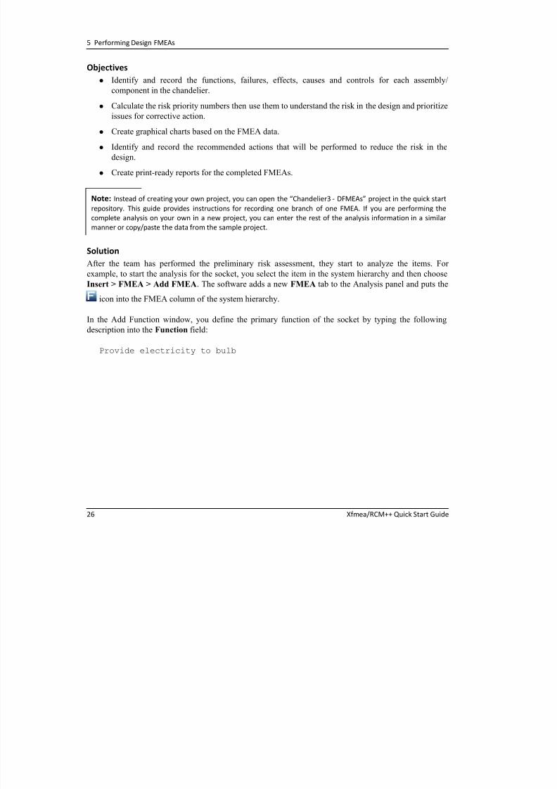
SolutionAfter the team has performed the preliminary risk assessment, they start to analyze the items. For
example, to start the analysis for the socket, you select the item in the system hierarchy and then choose
Insert > FMEA > Add FMEA. The software adds a new FMEA tab to the Analysis panel and puts the
icon into the FMEA column of the system hierarchy.
In the Add Function window, you define the primary function of the socket by typing the following
description into the Function field:
Provide electricity to bulb
Note: Instead of creating your own project, you can open the “Chandelier3 ‐ DFMEAs” project in the quick start
repository. This guide provides instructions for recording one branch of one FMEA. If you are performing the
complete analysis on your own in a new project, you can enter the rest of the analysis information in a similar
manner or copy/paste the data from the sample project.
5 1 F il M d d Eff t A l i (FMEA)

7/27/2019 QS_Xfmea.pdf
http://slidepdf.com/reader/full/qsxfmeapdf 31/102
5.1 Failure Modes and Effects Analysis (FMEA)
Xfmea/RCM++ Quick Start Guide 27
After adding the text, the Add Function window looks like this:
When you click the Add Failure button, the software saves the new function record and opens the Add
Failure window. You type the following description into the Failure field:
Short circuit occurs
You then click Add Effect button to open the Add Effect window.
For this project, the FMEA Structure is set to Grouped Effects and Causes (see page 11 in Chapter 3),
which means that the Add Effect window allows you to enter and rate more than one effect in the same
data entry window. The effect descriptions will be saved separately in the repository, but they will be
Tip: The Short Description field is a brief version of the record description that appears in diagrams where the full
description would be too long to display. If you do not enter text in this field, the software automatically populates
the field when you save the record (based on the first 50 characters of the record description). Note that the
description fields are not automatically updated if you later change one of them so you must be sure to make the
same changes to both fields if necessary.
5 Performing Design FMEAs

7/27/2019 QS_Xfmea.pdf
http://slidepdf.com/reader/full/qsxfmeapdf 32/102
5 Performing Design FMEAs
28 Xfmea/RCM++ Quick Start Guide
displayed together in the analysis views and report output. For the purpose of RPN calculation, the
software will automatically use the highest severity rating that has been defined for any of the possible
effects.
FMEA Structure: The FMEA structure setting on the General page of the Project Properties
window determines how the software will display the effect and cause records in the FMEA
hierarchy.
The Effects
Before
Causes
structure
displays
the
causes
under
the
effects
so
that
you
can
use
different severity ratings when calculating the RPN for different causes that are associated
with the same failure mode (if it is appropriate in the context of the particular analysis).
The Grouped Effects and Causes structure displays causes and effects at the same level of
the hierarchy under the failure mode that they are both associated with. When calculating
the RPN, the software will automatically choose the highest severity rating among all of the
effects that are defined for the failure mode.
The Causes
Before
Effects
structure
displays
the
effects
after
the
causes,
and
requires
that
there can be only one effect record per cause. For example, this may be appropriate for an
RCM analysis where the analysts identify functions, functional failures, failure modes
(i.e., causes) and then effects.
5 1 Failure Modes and Effects Analysis (FMEA)
7/27/2019 QS_Xfmea.pdf
http://slidepdf.com/reader/full/qsxfmeapdf 33/102
5.1 Failure Modes and Effects Analysis (FMEA)
Xfmea/RCM++ Quick Start Guide 29
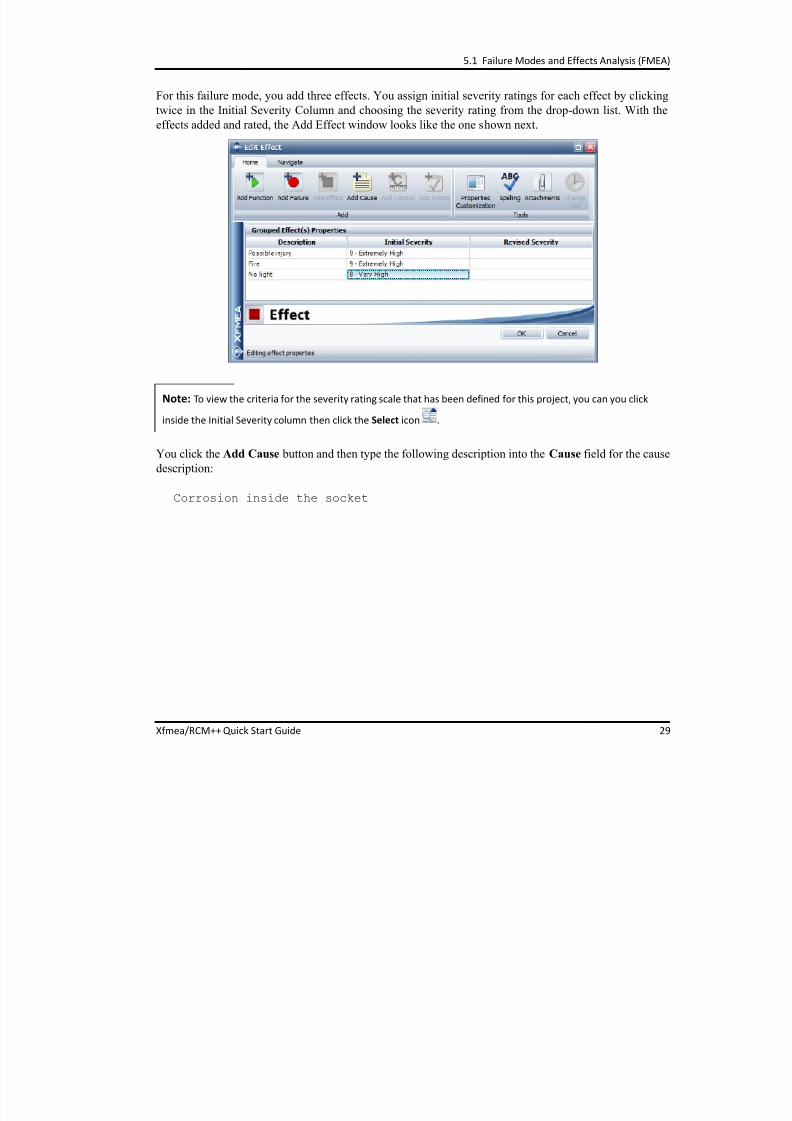
For this failure mode, you add three effects. You assign initial severity ratings for each effect by clicking
twice in the Initial Severity Column and choosing the severity rating from the drop-down list. With the
effects added and rated, the Add Effect window looks like the one shown next.
You click the Add Cause button and then type the following description into the Cause field for the cause
description:
Corrosion inside the socket
Note: To view the criteria for the severity rating scale that has been defined for this project, you can you click
inside the Initial Severity column then click the Select icon .
5 Performing Design FMEAs

7/27/2019 QS_Xfmea.pdf
http://slidepdf.com/reader/full/qsxfmeapdf 34/102
5 Performing Design FMEAs
30 Xfmea/RCM++ Quick Start Guide
The team will assign the initial occurrence and initial detection ratings after they have identified all of the
prevention and detection controls that might affect those ratings. So you click the Add Control button to
open the Add Control window.
You type the following description into the Control field:
Design guideline 1735 on material selection
Then you choose Prevention from the Control Type drop-down list and click OK to save the record and
close the window. The FMEA hierarchy looks like the picture shown next.
Controls: A control is a method or action that is planned or currently in place to reduce or eliminate
the risk associated with a particular failure cause. While the control types are configurable in the
software, practitioners usually classify the controls as “Prevention” or “Detection,” where:
Prevention controls
are
intended
to
reduce
the
likelihood
that
the
problem
will
occur.
Detection controls are intended to increase the likelihood that the problem will be detected
before it reaches the end user.
Analysts will typically consider all of the prevention controls when assigning the initial occurrence
rating to a cause and they will consider all of the detection controls when setting the initial
detection rating.
5.1 Failure Modes and Effects Analysis (FMEA)

7/27/2019 QS_Xfmea.pdf
http://slidepdf.com/reader/full/qsxfmeapdf 35/102
y ( )
Xfmea/RCM++ Quick Start Guide 31
Now that the controls have been defined, the next step is to go back to the cause record and record the
team’s occurrence and detection ratings. You double-click the “Corrosion inside the socket” cause to edit
the record properties.
In the Initial Occurrence field, you open the Select Occurrence window to see the occurrence rating scale
that has been assigned for this project. You choose 5 (1 in 500) and click OK to close the Select
Occurrence window.
You do the same for the Initial Detection field and click 5 - Medium. The following picture shows both
the occurrence and detection scales defined for this project.
5 Performing Design FMEAs

7/27/2019 QS_Xfmea.pdf
http://slidepdf.com/reader/full/qsxfmeapdf 36/102
32 Xfmea/RCM++ Quick Start Guide
You click OK to save the changes in the record and return to the FMEA hierarchy. Note that the calculated
RPN is displayed in the FMEA hierarchy, as shown next.
Then you continue recording the rest of the socket FMEA in a similar manner.
Evaluating the RPNs
Once the FMEA team has identified the functions, failure modes, effects, causes, controls and initial risk
priority numbers (RPNs) for all four of the chandelier assemblies/components, you begin to use the
calculated RPNs as a way to evaluate the risk in the design and to prioritize the issues for corrective
action.
After opening the Chandelier3 - DFMEAs project, you use the Priority Highlights feature to scan through
the FMEAs to see which issues meet the high, medium and low priority thresholds. To show the team
what thresholds have been established in this project, you choose Project > Management >
Configurable Settings > Interface Style to open the Edit Project Interface Style window then use the
Tip: Remember
that
while
the
quick
start
guide
describes
the
steps
for
only
one
branch
of
one
FMEA,
the
“Chandelier3 ‐ DFMEAs” project contains the completed FMEAs for all four assemblies/components. For the rest of
this example, you will be working with the entire data set available in the sample project.
5.1 Failure Modes and Effects Analysis (FMEA)

7/27/2019 QS_Xfmea.pdf
http://slidepdf.com/reader/full/qsxfmeapdf 37/102
Xfmea/RCM++ Quick Start Guide 33
navigation panel to display the FMEA > RPNs page. As shown below, when the highlight colors are
turned on for the analyses in this project, the issue will be colored green if the RPN is less than or equal to
30, yellow if the RPN is 31 to 299 and red if the RPN is 300 or higher.
The team accepts these settings so you click OK to close the interface style. Then you open an FMEA and
choose FMEA > Tools > Highlight Priority to turn on the priority highlights.
5 Performing Design FMEAs

7/27/2019 QS_Xfmea.pdf
http://slidepdf.com/reader/full/qsxfmeapdf 38/102
34 Xfmea/RCM++ Quick Start Guide
The team then looks at the highlighted RPNs in each FMEA. For example, the following picture shows the
calculated RPNs for the full socket FMEA, where one issue is highlighted in green to indicate low priority
and the rest are highlighted in yellow to indicate medium priority.
To look at the RPNs in a second way, you use the Filtered view to see lists of all the causes in each FMEA
sorted by RPN. For example, to create a list for the bulb FMEA, you select the item in the system
hierarchy then click the Filtered tab at the bottom of the Analysis panel and choose Causes from the
Filter By drop-down list in the upper-right corner. To sort the list by initial RPN, you click inside the
5.1 Failure Modes and Effects Analysis (FMEA)
7/27/2019 QS_Xfmea.pdf
http://slidepdf.com/reader/full/qsxfmeapdf 39/102
Xfmea/RCM++ Quick Start Guide 35
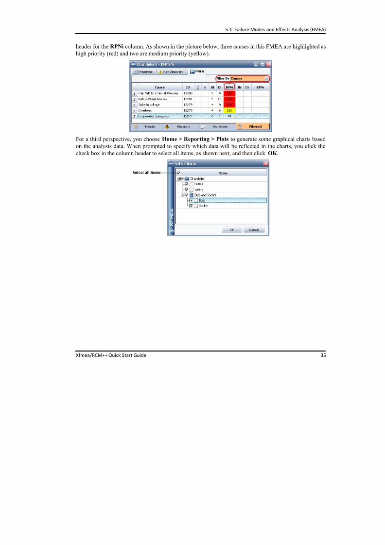
header for the RPNi column. As shown in the picture below, three causes in this FMEA are highlighted as
high priority (red) and two are medium priority (yellow).
For a third perspective, you choose Home > Reporting > Plots to generate some graphical charts based
on the analysis data. When prompted to specify which data will be reflected in the charts, you click the
check box in the column header to select all items, as shown next, and then click OK .
5 Performing Design FMEAs

7/27/2019 QS_Xfmea.pdf
http://slidepdf.com/reader/full/qsxfmeapdf 40/102
36 Xfmea/RCM++ Quick Start Guide
In the Plot Viewer window, you choose to create an RPN (Pareto) chart that displays the top ten issues
ranked by RPN. As shown next, when you point to a bar in the chart, the software displays the cause
description, the name and number of the item that the FMEA belongs to (in parentheses) and the RPN.
Next, you change the plot type to Occurrence/Severity Matrix, which displays the severity ratings on the
horizontal axis and occurrence ratings on the vertical axis, then plots each cause at the intersection of its
severity and occurrence ratings. You can see that when the analysis considers only the S and O
components of the RPN equation, all of the issues fall into the “High Priority” range. Once again, pointing
Tip: The Plot Type field allows you to select which chart will be displayed. When a bar chart is selected, the
Display Range area allows you to specify the number of records you want to be displayed in the plot. For example,
since there
are
17
cause
records
in
the
chandelier
FMEAs,
you
could
specify
to
view
records
1 through
5,
1 through
10, 1 through 17, etc.
5.1 Failure Modes and Effects Analysis (FMEA)

7/27/2019 QS_Xfmea.pdf
http://slidepdf.com/reader/full/qsxfmeapdf 41/102
Xfmea/RCM++ Quick Start Guide 37
to a shape in the matrix displays the name of the failure cause and other relevant details, as shown in the
following picture.
After you are done reviewing the plots, you close the Plot Viewer window.
Managing Recommended Actions
The next step is to identify, assign and track the completion of the recommended actions that will help to
reduce the risk associated with potential failures.
The FMEA team identifies the actions that need to be performed to improve the chandelier design, and
you record the details in the appropriate locations within each FMEA. For example the team decides to
address the “Corrosion inside the socket” issue by developing a corrosion test protocol.
5 Performing Design FMEAs

7/27/2019 QS_Xfmea.pdf
http://slidepdf.com/reader/full/qsxfmeapdf 42/102
38 Xfmea/RCM++ Quick Start Guide
To create the action, you select the socket in the system hierarchy. Then you return to the Hierarchy view
of the FMEA and select the “Corrosion inside the socket” cause. After you choose FMEA > FMEA
Records > Actions to open the Add Action window, you set the action properties as shown in thefollowing picture.
5.1 Failure Modes and Effects Analysis (FMEA)

7/27/2019 QS_Xfmea.pdf
http://slidepdf.com/reader/full/qsxfmeapdf 43/102
Xfmea/RCM++ Quick Start Guide 39
Generating a Report
When you are ready to generate a print-ready report that displays the analysis information, you choose
Home > Reporting > Reports. The Reports window provides a choice of predefined and custom report
forms that can be included in a report document generated in either Microsoft Word or Excel.
You decide that the report should show:
The rating scales used
The risk discovery questions and answers
An FMEA spreadsheet that is consistent with Form A in the published AIAG FMEA-4 guidelines
A list of the causes ranked by initial RPN
A list of the recommended actions
To build the desired report, you do the following:
Select the check box in the header of the Select Items area to specify that the data from all four
FMEAs will be included in the report.
Click the Exclude All button (<<) to remove any existing reports in the Selected Reports area.
Actions Management in Xfmea/RCM++: One of the most costly mistakes among FMEA
practitioners is the failure to follow up and track the completion of recommended actions. Xfmea/
RCM++ provides multiple features to help your organization implement the improvements that are
identified during the FMEA activity. For example:
You can assign an action to any user with an account in the Synthesis repository and that
action will display in the user's My Portal.
You can generate e‐mails, both automatically and manually, when certain conditions are met
(e.g., action creation, action modification, action completion).
You can generate reports about the actions defined in the analysis project, such as a list of
actions sorted by due date or action category.
Actions are Synthesis resources, which means that they can be used in any FMEA within the
same project. Changes made in one place are reflected everywhere the action is used.
5 Performing Design FMEAs

7/27/2019 QS_Xfmea.pdf
http://slidepdf.com/reader/full/qsxfmeapdf 44/102
40 Xfmea/RCM++ Quick Start Guide
Select Excel Spreadsheet in the Select Output Type area.
Select the five desired report forms from the Available Reports area and move them to the
Selected Reports area.
For example, to include the causes ranked by initial RPN, you select the Causes report in the FMEA
Records section in the Available Reports area. To move it to the Selected Reports area, you click the
report and then drag it to the desired location in the Selected Reports area. To sort it by initial RPN,
you click inside the Sort By column and choose Initial RPN from the drop-down list.
After selecting the reports, the window will look like this:
You click Generate Report and specify the name and location where the report file will be saved. The
report will then open automatically in Microsoft Excel.
5.1 Failure Modes and Effects Analysis (FMEA)

7/27/2019 QS_Xfmea.pdf
http://slidepdf.com/reader/full/qsxfmeapdf 45/102
Xfmea/RCM++ Quick Start Guide 41
Updating the DFR Planner
After you are finished creating all the FMEAs and performing all the tasks associated with that, you can
indicate in the DFR planner that this step of the Design for Reliability process has been completed. Youreturn to the planner by selecting the chandelier in the system hierarchy and then viewing the DFR Planner
tab on the Analysis panel. After double-clicking the “DFMEA” gate and entering a completion date, the
plan appears as shown next.

7/27/2019 QS_Xfmea.pdf
http://slidepdf.com/reader/full/qsxfmeapdf 46/102

7/27/2019 QS_Xfmea.pdf
http://slidepdf.com/reader/full/qsxfmeapdf 47/102
Xfmea/RCM++ Quick Start Guide 43
The innovative failure modes and reliability analysis (FMRA) tool in
Xfmea/RCM++ enables you to use the information from the system
hierarchy and FMEAs to perform a variety of reliability-related analyses.
One application for this tool is to generate a preliminary quantitative
estimate of the system’s baseline reliability using the qualitative occurrence
ratings specified in the project’s FMEAs.
Specifically, you can use the occurrence ratings to assign quantitative
models to describe the probability of failure due to each failure cause
identified in the FMEA, and then you can estimate the system’s reliability
based on those models. As better information about the system becomes
available, you can then update the FMRA to improve your understanding of
the system’s reliability and the components/failure modes that have the
biggest impact on that reliability.
6.1 Using the FMRA to Generate a Baseline Reliability Estimate
After completing the assembly- and component-level FMEAs (see Chapter 5), the next step in the DFR
planner is to generate a baseline reliability estimate for the chandelier. Since little data is available at this
point in the process, you will start by using the occurrence ratings assigned in the FMEAs.
Objectives
Display the FMRA interface and customize it so you only see the columns that are relevant for
estimating the system’s reliability.
Produce a first draft of the FMRA and use it to generate a preliminary estimate of the system’s
baseline reliability.
FMRA‐Reliability
Estimation 6
Failure modes
and reliability
analysis (FMRA)
Estimating the
system reliability
Project baselines
FMRA vetting
Watch a video of this example at
http://www.ReliaSoft.tv/xfmea/startguide/xfmea_qsg_6.html.
6 FMRA ‐ Reliability Estimation
C b li f h i j “ i ” b f b i dj i h

7/27/2019 QS_Xfmea.pdf
http://slidepdf.com/reader/full/qsxfmeapdf 48/102
44 Xfmea/RCM++ Quick Start Guide
Create a baseline of the entire project to use as a “restore point” before you begin adjusting the
analysis.
Begin the “FMRA vetting” process by reviewing and updating the first draft.
Solution
First, you choose View > FMRA > Show FMRA. The FMRA interface shows each item from the systemhierarchy, along with all the functions, failures and causes that are defined in the FMEAs. The columns in
the FMRA display various kinds of information and analysis results for each record. To select which
columns to show on your computer, you right-click a column header in the FMRA and choose Customize
Columns. You only want to see the columns that are relevant to estimating the system’s reliability (and
the reliabilities of its components), so you make the selections shown next.
When you return to the FMRA hierarchy, you click the system (i.e., the top-level item) and enter 5000 for
the Operating Time on the properties tab to estimate the reliability at 5,000 hours.
Note: Instead of creating your own project, you can open the “Chandelier4 ‐ FMRA Draft” project in the quick
start repository to see the first draft of the FMRA. The “Chandelier5 ‐ FMRA Revised” project contains the updated
version of the analysis.
6.1 Using the FMRA to Generate a Baseline Reliability Estimate
N t h P j t > M t > C fi bl S tti > O t th

7/27/2019 QS_Xfmea.pdf
http://slidepdf.com/reader/full/qsxfmeapdf 49/102
Xfmea/RCM++ Quick Start Guide 45
Next, you choose Project > Management > Configurable Settings > Occurrence to see the occurrence
scale that is in effect for this project and confirm that the settings will allow the software to create
appropriate probability of failure models for use in the FMRA.
The probability of failure model that is associated with each rating in the scale will be determined by the
number in the Quantitative Value column and the option selected in the Treat Quantitative Values As
area.
For example, if Fixed probability of failure (Q) were selected, then a cause with a rating of 4 (1 in 1,000)
would always be assigned a fixed probability of 0.1% (or 0.001) regardless of the operating time.
However, in this case, you know that the FMEA team assigned occurrence ratings based on the probabilitythat the failure would occur by 1,000 hours of operation, so it is possible to use a time-dependent
exponential distribution instead of a fixed probability. This will allow the software to calculate the
probability of failure for any operating time specified for the analysis (which is 5,000 hours in this case).
You make sure the Exponential distribution option is selected and you set T to 1,000 hours. With this
6 FMRA ‐ Reliability Estimation
setting an exponential model will be built for each rating using the probability of failure entered in the

7/27/2019 QS_Xfmea.pdf
http://slidepdf.com/reader/full/qsxfmeapdf 50/102
46 Xfmea/RCM++ Quick Start Guide
setting, an exponential model will be built for each rating using the probability of failure entered in the
Quantitative Value field and the time specified for T .
After confirming that the quantitative values reflect the criteria that the team used for the FMEAs, you
click OK to close the window. The next step is to configure the software so each cause is automatically
assigned an appropriate model based on the initial occurrence ratings from the FMEAs. While you could
do this by modifying the reliability policy for each cause individually (on the Properties tab), you know it
Probability Models in the FMRA: If you choose to associate exponential models with the
occurrence ratings, the parameter for each model will be estimated using the same calculation
performed in the Quick Parameter Estimator. The probability of failure (Q) and time (T) that you
specified in the scale are used to solve for the lambda parameter of the exponential distribution as
follows:
Note that if you used the Application Setup window to configure the software to use mean time to
failure (MTTF) as the parameter of the exponential distribution instead of lambda, the application
will first
solve
for
lambda
and
then
calculate
the
reciprocal
of
lambda
to
obtain
the
MTTF.
1 Q T – R T e t – = =
1 Q T – ln –
t ----------------------------------- =
6.1 Using the FMRA to Generate a Baseline Reliability Estimate
will be faster to update all the causes simultaneously by choosing FMRA > RAM Analysis > Policy

7/27/2019 QS_Xfmea.pdf
http://slidepdf.com/reader/full/qsxfmeapdf 51/102
Xfmea/RCM++ Quick Start Guide 47
will be faster to update all the causes simultaneously by choosing FMRA > RAM Analysis > Policy
Update. In the window that appears, you select Cause and choose Based on Initial Occurrence from the
drop-down list.
After you click OK , the reliability policy type for each cause record is changed to Based on Initial
Occurrence. Now, when you click any cause record, you can see the updated policy and view information
about the assigned model on the Properties tab.
For example, for the “Corrosion” cause shown next, the name of the model indicates that it is based on an
Occurrence rating of 6, which in this project corresponds to a probability of 1 in 100 at 1,000 hours. The
information in brackets indicates that the model uses a 1-parameter exponential distribution (EX1), andthe value of lambda is 0.000010.
6 FMRA ‐ Reliability Estimation
You scan through the FMRA to make sure that all of the models were assigned properly and then choose

7/27/2019 QS_Xfmea.pdf
http://slidepdf.com/reader/full/qsxfmeapdf 52/102
48 Xfmea/RCM++ Quick Start Guide
ou sc oug e o e su e o e ode s we e ss g ed p ope y d e c oose
FMRA > RAM Analysis > Calculate (Reliability) to solve for the system’s baseline reliability. To color-
code the reliability values (which uses a gradient from green to red to indicate which are the highest valuesand which are the lowest), you choose FMRA > RAM Analysis > Highlight.
The results are displayed in the FMRA as shown next. (In this picture, the records for the frame and wiring
are hidden, but they can be shown by clicking the + button and expanding those parts of the hierarchy.)
The value shown in the Reliability (Analytical) column for the top-level item is the computed baseline
reliability (84.95%) for the entire chandelier at 5,000 hours. To calculate this value, the occurrence rating
for each cause was converted into an exponential distribution. Then these distributions were used to obtain
Note: By default, the software assumes that the occurrence of any one cause is sufficient for the entire system to
fail (i.e., it assumes a reliability‐wise series configuration). If you also have ReliaSoft's BlockSim software, you can
synchronize the FMRA in Xfmea/RCM++ with RBDs or fault trees in BlockSim. You can then use the RBDs/fault
trees to define more complex reliability‐wise configurations in your FMRA, if appropriate. For details, please
consult the Synthesis Platform guide or one of the product help files.
6.1 Using the FMRA to Generate a Baseline Reliability Estimate
the reliability for each failure mode (i.e., the probability that none of the causes for that failure mode

7/27/2019 QS_Xfmea.pdf
http://slidepdf.com/reader/full/qsxfmeapdf 53/102
Xfmea/RCM++ Quick Start Guide 49
y ( p y
would occur). Finally, these reliabilities were “rolled up” to get the reliabilities of the components/
assemblies and then the system.
When you generate this first draft of the FMRA, you are aware that the computed values may be far from
the true reliabilities. The next step is to work through the “FMRA vetting” process by carefully reviewing
and updating the analysis with the goal of improving its accuracy and thereby achieving a more accurate
understanding of the system’s baseline reliability.
Note: In this example, since we are assuming a reliability‐wise series configuration, “rolling up” from a lower
level is done by simply multiplying the calculated reliability values at the lower level and assigning the result to the
higher‐level record that is set to “Inherit.” For example, looking at the “Overheat” and “Spike in voltage” cause
records, the reliability is the reciprocal of the cause’s probability of occurrence (i.e., the probability that the cause
will not occur before the specified operating time). So, according to the above FMRA, the probability of the bulb
not overheating before 5,000 hours is estimated to be 99.50%, and the probability of a spike in voltage not
occurring
is
also
99.50%.
Thus, the
probability
of
the
bulb
not
shattering
before
5,000
hours
(i.e.,
the
failure
mode’s reliability) is 99.50% x 99.50% = 99.00%. This is then multiplied by the reliabilities of the other failure
modes under the “Provide light” function to obtain the reliability of the bulb.
FMRA Vetting: In general, the FMRA vetting process involves these two steps:
Cleaning Up
During this step, you review the failure causes that are being considered in the analysis and
perform any cleanup that may be required to make sure the FMRA considers all the causes
that impact
the
system’s
reliability,
but
does
not
consider
causes
that
don't.
Reviewing and Validating Inputs
During this step, you examine the calculated reliability estimates for each record to see if
they fit your expectations. If not, you determine which inputs to the FMRA and DFMEAs
might need to be revised with better information.
The ReliaWiki resource portal provides more information about the FMRA vetting process at:
http://www.ReliaWiki.org/index.php/Using_FMRA_to_Estimate_Baseline_Reliability.
6 FMRA ‐ Reliability Estimation
Creating a Baseline

7/27/2019 QS_Xfmea.pdf
http://slidepdf.com/reader/full/qsxfmeapdf 54/102
50 Xfmea/RCM++ Quick Start Guide
Before you begin the vetting process, you decide to create a “baseline” of the entire project that you can
restore or roll back to at any point in the future.
To create the baseline, you choose Project > Management > Project Baselines > Create Baseline and
enter text to indicate the purpose of the baseline, as shown next.
You click OK to create the baseline. Then you choose Project > Management > Project Baselines >
Restore Baseline and open the Restore Baseline window to confirm that the baseline was created.
If needed in the future, you will have the option to either roll back the existing project to the state it was in
when this baseline was created (by choosing Overwrite existing project) or to restore the baseline as a
6.1 Using the FMRA to Generate a Baseline Reliability Estimate
new project that is separate from the one you are currently working with (by choosing Create new

7/27/2019 QS_Xfmea.pdf
http://slidepdf.com/reader/full/qsxfmeapdf 55/102
Xfmea/RCM++ Quick Start Guide 51
project).
Reviewing and Updating the FMRA
After saving a baseline of the project, you examine the FMRA and look for ways to improve it. One issue
you notice is that the “Bulb wattage too low” failure cause (which occurs if the user installs the wrongtype of bulb) was something that needed to be considered during the FMEA, but it should not affect the
chandelier’s calculated reliability.
To prevent the software from considering this cause, you select it in the FMRA. Then, on the Properties
tab, you set the reliability policy to Define at this level. By default, the software will assign a model with
100% reliability (“Default - Cannot Fail”), as shown next.
By assigning this default model, the cause record will essentially be ignored in the reliability calculations
because the cause reliability will always be 100%.
Tip: The commands in the Project tab of the Ribbon allow you to create or restore any baseline that is associated
with the project that is currently open. In addition, authorized users can choose File > Manage Repository >
Project Baselines in order to view and manage all of the stored baselines for any of the projects in the repository.
6 FMRA ‐ Reliability Estimation
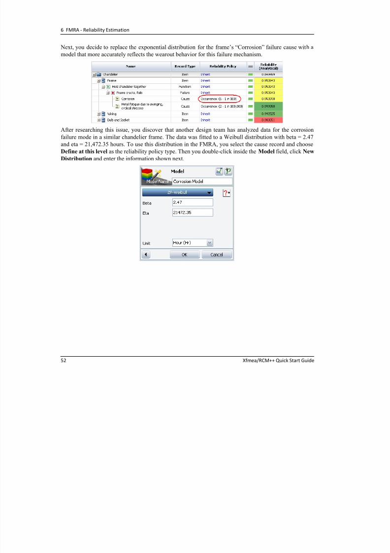
Next, you decide to replace the exponential distribution for the frame’s “Corrosion” failure cause with a
d l th t t l fl t th t b h i f thi f il h i
7/27/2019 QS_Xfmea.pdf
http://slidepdf.com/reader/full/qsxfmeapdf 56/102
52 Xfmea/RCM++ Quick Start Guide
model that more accurately reflects the wearout behavior for this failure mechanism.
After researching this issue, you discover that another design team has analyzed data for the corrosion
failure mode in a similar chandelier frame. The data was fitted to a Weibull distribution with beta = 2.47
and eta = 21,472.35 hours. To use this distribution in the FMRA, you select the cause record and choose
Define at this level as the reliability policy type. Then you double-click inside the Model field, click New
Distribution and enter the information shown next.
6.1 Using the FMRA to Generate a Baseline Reliability Estimate
After you click OK , the software creates a probability of failure model that uses the distribution you
defined and it assigns this model to the record

7/27/2019 QS_Xfmea.pdf
http://slidepdf.com/reader/full/qsxfmeapdf 57/102
Xfmea/RCM++ Quick Start Guide 53
defined, and it assigns this model to the record.
Finally, you recalculate the FMRA and see that the system’s reliability estimate is now 87.79%.
Tip: As you can see, you don’t have to use models that are based on the qualitative occurrence ratings from the
FMEAs. The Synthesis Platform allows you to use any probability model that is created within any Synthesis‐
enabled application (e.g., Weibull++, ALTA or BlockSim) or create independent model resources that are not
linked to data sets. In this case, you created a model without linking to an analyzed data set. However, if you had
access to the data for the corrosion failure mode, you could have used Weibull++ to analyze the data and publish
the results as a model. With this approach, if the underlying data analysis ever changes, you have the option to
republish the model with updated information and any Synthesis analysis that uses this model would be updated
automatically as well.
6 FMRA ‐ Reliability Estimation
Updating the DFR Planner
O fi i h tti th FMRA i di t i th DFR l th t thi t f th D i f

7/27/2019 QS_Xfmea.pdf
http://slidepdf.com/reader/full/qsxfmeapdf 58/102
54 Xfmea/RCM++ Quick Start Guide
Once you finish vetting the FMRA, you indicate in the DFR planner that this step of the Design for
Reliability process has been completed. You return to the planner by selecting the chandelier in theFMRA hierarchy and then viewing the DFR Planner tab on the Analysis panel. After double-clicking the
“Compute Baseline Reliability” gate and entering a completion date, the plan appears as shown next.

7/27/2019 QS_Xfmea.pdf
http://slidepdf.com/reader/full/qsxfmeapdf 59/102
Xfmea/RCM++ Quick Start Guide 55
The example in Chapter 6 demonstrated how the new failure modes and
reliability analysis (FMRA) tool can be used to estimate a system's baseline
reliability using whatever is currently known about the probability of occurrence for potential failure modes and/or the reliability of the
components. The analysis can continue to be refined and improved over
time as better information becomes available. In RCM++, this tool can also
be used to perform simulation-based calculations that take into account the
maintenance characteristics of a repairable system.
Specifically, RCM++ uses a Synthesis resource called the “Universal Reliability Definition (URD)” to
record not only the reliability characteristics, but also the corrective and preventive maintenancecharacteristics for repairable components. The software uses this information to simulate the operation of
the system for a specified period of operating time in order to calculate a variety of useful metrics,
including the reliability, availability and operating costs. This chapter presents an example in which these
simulation results are used to estimate the availability and operating costs that can be expected from a
specified maintenance strategy. Similar techniques can also be used for comparing different possible
maintenance strategies to determine which approach is expected to provide the desired level of availability
for the minimum cost.
FMRA‐Maintenance
Planning in RCM++ 7
Note: This chapter describes steps for performing calculations that are
available only in RCM++.
Tasks, crews, spare part pools
Maintenance
costs
Availability
Watch a video of this example at
http://www.ReliaSoft.tv/rcm/startguide/rcm_qsg_7_1.html
7 FMRA ‐ Maintenance Planning in RCM++
7.1 Using the FMRA to Estimate Availability and Maintenance Costs

7/27/2019 QS_Xfmea.pdf
http://slidepdf.com/reader/full/qsxfmeapdf 60/102
56 Xfmea/RCM++ Quick Start Guide
After you finish vetting the FMRA and obtain the initial design reliability of the chandelier (Chapter 6),
you are asked to estimate the availability of the system and the maintenance costs that are expected to beincurred by the user over 2 years of use.
Objectives
Display the FMRA interface and customize it so you only see the columns that are relevant for
estimating availability and maintenance costs.
Define all the maintenance tasks for the chandelier’s bulb and socket.
Calculate the chandelier’s availability over 2 years (1,000 hours) of usage, and obtain the
maintenance costs that are expected over this time.
Solution
In RCM++ you first choose View > FMRA > Show FMRA. To select which columns in the FMRA to
show on your computer, you right-click a column header in the FMRA and choose Customize Columns.
Note: This example starts with the completed FMRA in the “Chandelier6 ‐ FMRA Final” project in the quick start
repository. Note that because these calculations only need component‐level information (i.e., we are only
concerned with system availability and the maintenance of components, not with the influence of particular
failure modes, etc.), the completed FMRA does not show any FMEA records. Instead, all of the reliability
information is
defined
at
the
item
level,
and
you
will
define
maintenance
characteristics
at
the
item
level
as
well.
To see the FMRA with all the maintenance tasks already defined, see the “Chandelier7 ‐ FMRA Maintenance”
project in the quick start repository. You can follow the steps below to see how the example was performed in the
sample project, or you can copy data/analyses from the project to help you perform the steps on your own.
7.1 Using the FMRA to Estimate Availability and Maintenance Costs
You only want to see the columns that are relevant to estimating availability and maintenance costs, so
you make the selections shown next.

7/27/2019 QS_Xfmea.pdf
http://slidepdf.com/reader/full/qsxfmeapdf 61/102
Xfmea/RCM++ Quick Start Guide 57
Because you wish to estimate the availability and maintenance costs at 2 years (or 1,000 hours) of
operation, you click the top-level system in the FMRA and enter 1,000 for the Operating Time on the
Properties tab.
Since the owner of the chandelier is unlikely to repair it when it fails due to problems with the frame or
wiring, only the maintenance of the bulb and socket will be considered. To consider the maintenance tasks
associated with these components, you will need to create and define a maintenance task resource for both
the bulb and the socket.
7 FMRA ‐ Maintenance Planning in RCM++
Defining a New Maintenance Task for the Bulb
To define a maintenance task for the bulb, you need to add a task resource to the Universal Reliability

7/27/2019 QS_Xfmea.pdf
http://slidepdf.com/reader/full/qsxfmeapdf 62/102
58 Xfmea/RCM++ Quick Start Guide
, y y
Definition (URD) that’s currently assigned to the bulb. To do this, you select the bulb in the FMRA and,on the Properties tab, you double-click inside the Corrective Task field.
In the Corrective Task Wizard that appears, you click the Add icon to open the Maintenance Task
window.
In this case, maintenance of the bulb will consist of all the tasks associated with replacing it. The
following is assumed about the bulb’s replacement:
The bulb will be replaced only after it has already failed, and it will be replaced by the owner of the
chandelier.
The owner does not keep spare bulbs on hand and will have to purchase one from a nearby home
improvement store. The total time for the trip is 2 hours on average (with a standard deviation of 20 minutes), and
the cost of transportation (fuel, etc.) is $6 on average (with a standard deviation of $0.50).
The cost for a new bulb is $5 on average (with a standard deviation of $0.50).
7.1 Using the FMRA to Estimate Availability and Maintenance Costs
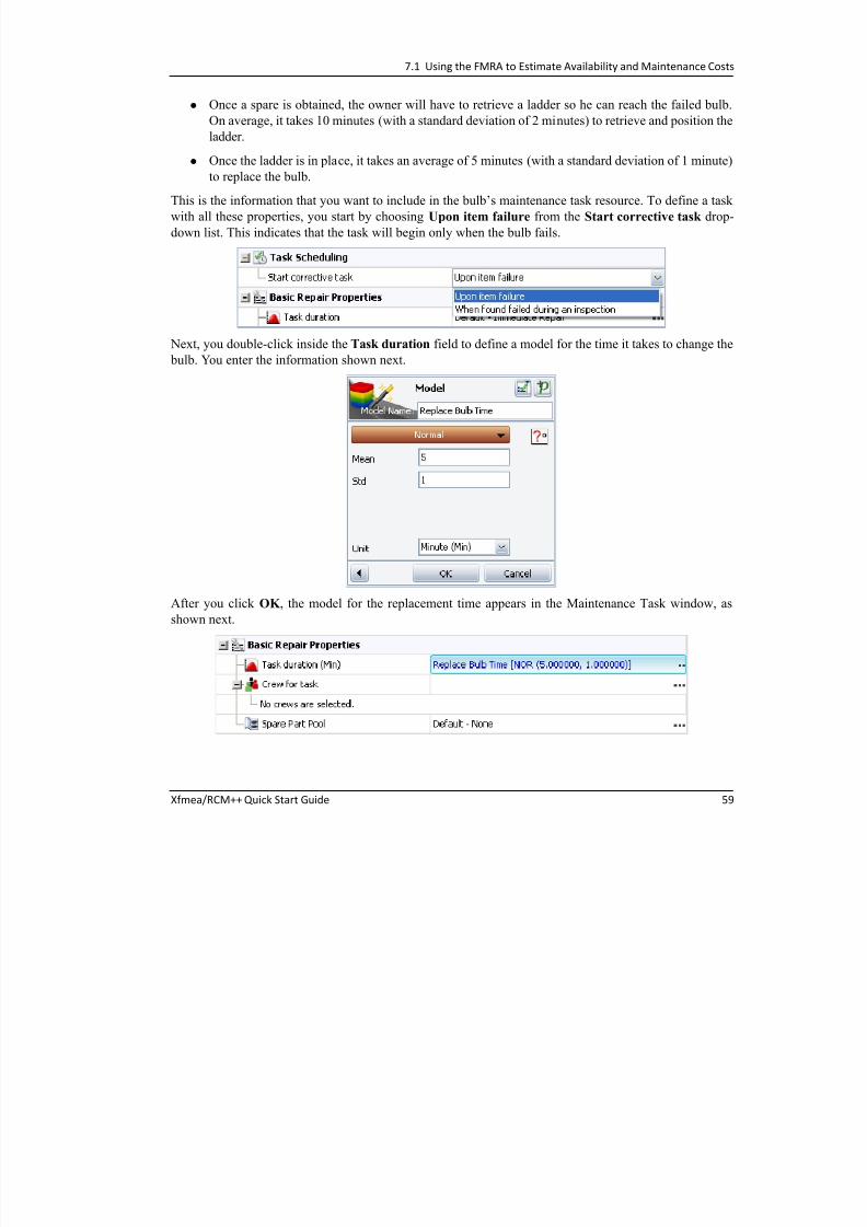
Once a spare is obtained, the owner will have to retrieve a ladder so he can reach the failed bulb.
On average, it takes 10 minutes (with a standard deviation of 2 minutes) to retrieve and position the
l dd
7/27/2019 QS_Xfmea.pdf
http://slidepdf.com/reader/full/qsxfmeapdf 63/102
Xfmea/RCM++ Quick Start Guide 59
ladder.
Once the ladder is in place, it takes an average of 5 minutes (with a standard deviation of 1 minute)
to replace the bulb.
This is the information that you want to include in the bulb’s maintenance task resource. To define a task
with all these properties, you start by choosing Upon item failure from the Start corrective task drop-
down list. This indicates that the task will begin only when the bulb fails.
Next, you double-click inside the Task duration field to define a model for the time it takes to change the
bulb. You enter the information shown next.
After you click OK , the model for the replacement time appears in the Maintenance Task window, as
shown next.
7 FMRA ‐ Maintenance Planning in RCM++
Next, you want to define a crew so you can indicate who will perform the task and take into account the
time required to retrieve the ladder. You double-click inside the Crew for task field and click the Add
icon The Crew window appears as shown next
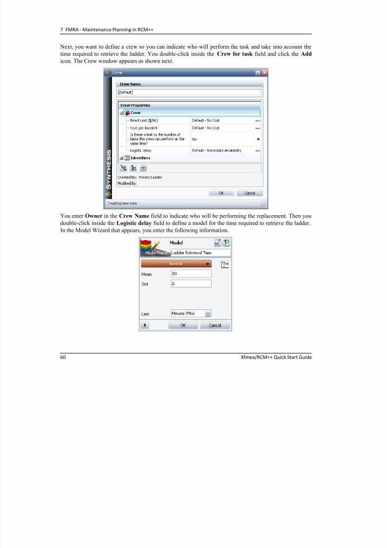
7/27/2019 QS_Xfmea.pdf
http://slidepdf.com/reader/full/qsxfmeapdf 64/102
60 Xfmea/RCM++ Quick Start Guide
icon. The Crew window appears as shown next.
You enter Owner in the Crew Name field to indicate who will be performing the replacement. Then you
double-click inside the Logistic delay field to define a model for the time required to retrieve the ladder.
In the Model Wizard that appears, you enter the following information.
7.1 Using the FMRA to Estimate Availability and Maintenance Costs
After you click OK , you can see the model that was defined for the ladder, as shown next.

7/27/2019 QS_Xfmea.pdf
http://slidepdf.com/reader/full/qsxfmeapdf 65/102
Xfmea/RCM++ Quick Start Guide 61
You click OK to close the Crew window and return to the Maintenance Task window.
What you need to do now is take into account the transportation-related costs and delays, as well as the
cost of the spare bulb itself. You double-click inside the Spare Part Pool field and then click the Add
icon to create a new spare part pool resource. You enter Bulb Purchase for the spare part pool’s name.
Then, to define a model for the bulb’s cost, you double-click inside the Direct cost per dispensed item
field, then you enter the information shown next and click OK .
7 FMRA ‐ Maintenance Planning in RCM++
To define a model for the round trip time required to get to the home improvement store, you double-click
inside the Logistic time for spare acquisition field and enter the information shown next. (Note that both
mean and standard deviation are entered in minutes.)

7/27/2019 QS_Xfmea.pdf
http://slidepdf.com/reader/full/qsxfmeapdf 66/102
62 Xfmea/RCM++ Quick Start Guide
mean and standard deviation are entered in minutes.)
After you click OK , you can see the models defined for the bulb’s price and the drive to the store.
7.1 Using the FMRA to Estimate Availability and Maintenance Costs
The only part of the task left to define is the cost of transportation to the store (e.g., fuel). You click OK to
close the Spare Part Pool window and return to the Maintenance Task window. Then you double-click
inside the Cost per task field under the Additional Costs to Consider header.

7/27/2019 QS_Xfmea.pdf
http://slidepdf.com/reader/full/qsxfmeapdf 67/102
Xfmea/RCM++ Quick Start Guide 63
p
In the Model Wizard that appears, you enter this information.
7 FMRA ‐ Maintenance Planning in RCM++
After you click OK , you can view all the properties defined for the bulb replacement task, as shown next.

7/27/2019 QS_Xfmea.pdf
http://slidepdf.com/reader/full/qsxfmeapdf 68/102
64 Xfmea/RCM++ Quick Start Guide
You save the new task by clicking OK , and now you can see that the new task is part of the bulb’sreliability policy.
7.1 Using the FMRA to Estimate Availability and Maintenance Costs
Defining a New Maintenance Task for the Socket
To define a maintenance task for the socket, you follow steps similar to those described above.

7/27/2019 QS_Xfmea.pdf
http://slidepdf.com/reader/full/qsxfmeapdf 69/102
Xfmea/RCM++ Quick Start Guide 65
In this case, maintenance of the socket will consist of all the tasks associated with hiring an electrician to
replace it. The following is assumed about the socket replacement:
The task is performed only after the socket fails, and it will be performed by an electrician.
On average, it takes 4 days (with a standard deviation of 1 day) for the electrician to arrive after the
owner calls to schedule an appointment.
Once he arrives, the electrician will charge $90 per hour, plus a fixed fee of $50 per visit. In addition, there is a $50 charge for the spare socket that will be used for the repair.
There is also a 50% chance that the electrician will not have a spare socket available. If no
socket is available, the electrician will drive to a nearby home improvement store (the same
store where the owner buys spare bulbs) to purchase one.
It takes an average of 60 minutes (with a standard deviation of 20 minutes) to perform the socket
replacement.
You start by choosing Upon item failure from the Start corrective task drop-down list. Next, you
double-click inside the Task duration field to define a model for the time it takes for the electrician to
repair the socket. You enter the information shown next.
7 FMRA ‐ Maintenance Planning in RCM++
After you click OK , the model for the replacement time appears in the Maintenance Task window, as
shown next.

7/27/2019 QS_Xfmea.pdf
http://slidepdf.com/reader/full/qsxfmeapdf 70/102
66 Xfmea/RCM++ Quick Start Guide
Next, you want to define a crew so you can take into account how much the electrician charges and how
long it takes him to arrive after you first schedule an appointment. You double-click inside the Crew for
task field and click the Add icon. In the Crew window that appears, you enter Electrician for the crew
name. Then you double-click inside the Direct cost field to specify how much the electrician charges per
hour. In the Model Wizard that appears, you click the New Constant button.
Then you enter the information shown next.
To define the flat fee that the electrician charges per visit, you double-click inside the Cost per incident
field and click the New Constant button. Then you enter Crew - Per Incident for this model’s name and
enter 50 in the Constant Cost field.
7.1 Using the FMRA to Estimate Availability and Maintenance Costs
To define a model that describes the time it takes for the electrician to arrive after you first call to schedule
an appointment, you double-click inside the Logistic delay field and enter this information.
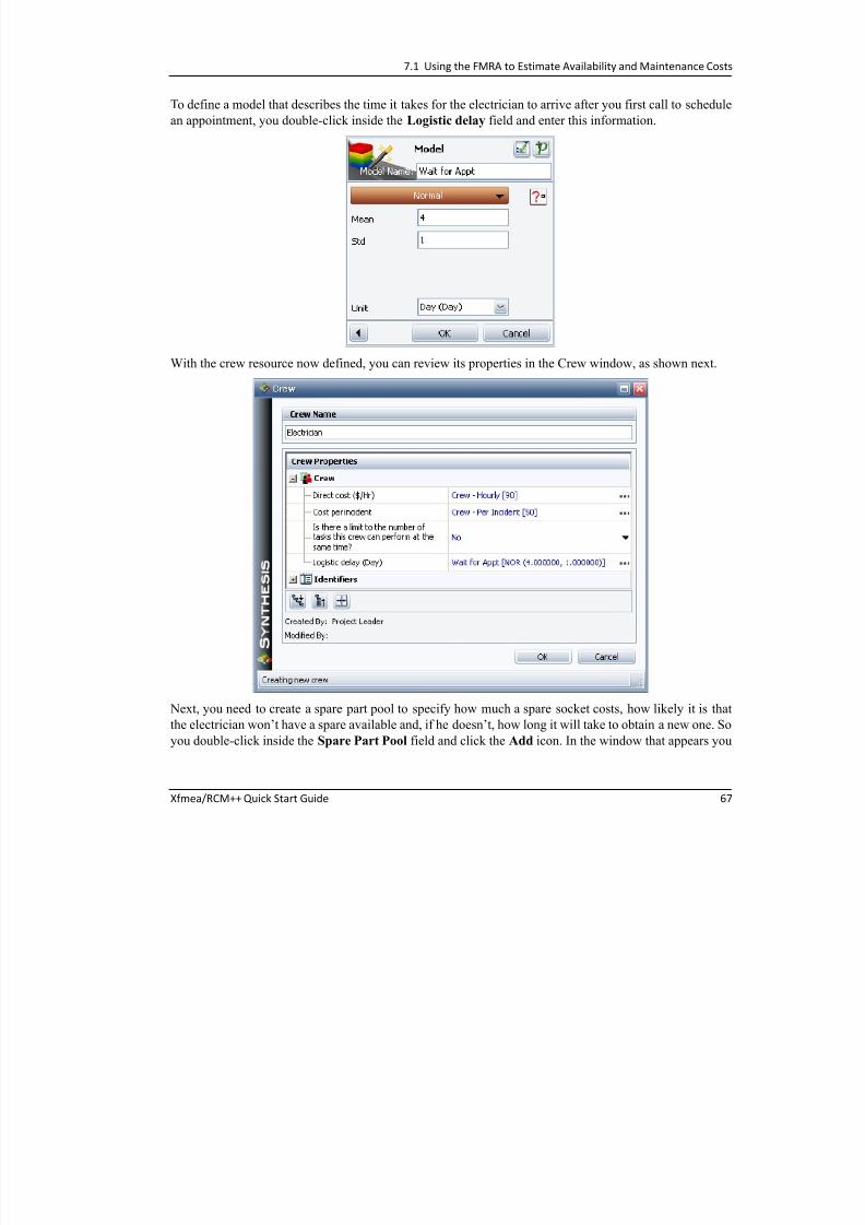
7/27/2019 QS_Xfmea.pdf
http://slidepdf.com/reader/full/qsxfmeapdf 71/102
Xfmea/RCM++ Quick Start Guide 67
With the crew resource now defined, you can review its properties in the Crew window, as shown next.
Next, you need to create a spare part pool to specify how much a spare socket costs, how likely it is that
the electrician won’t have a spare available and, if he doesn’t, how long it will take to obtain a new one. So
you double-click inside the Spare Part Pool field and click the Add icon. In the window that appears you
7 FMRA ‐ Maintenance Planning in RCM++
enter Socket Part for the spare part pool name, and then you double-click inside the Direct cost per
dispensed item field and then click the New Constant button.
In the Model Wizard that appears you enter Socket Price for the model’s name and enter 50 in the

7/27/2019 QS_Xfmea.pdf
http://slidepdf.com/reader/full/qsxfmeapdf 72/102
68 Xfmea/RCM++ Quick Start Guide
In the Model Wizard that appears, you enter Socket Price for the model s name and enter 50 in theConstant Cost field. Then you choose Fixed probability of stockout from the Spare acquisition type
drop-down list. This indicates that the probability that the electrician will not have a spare socket available
is always the same. In the Fixed probability value field, you specify that the probability of having no
spare available is always 0.5.
If the electrician does not have a spare on hand, he will have to take the time to drive to the home
improvement store and buy a new one. So you select the Can obtain emergency spares if needed check
box under the Emergency Spare Provisions heading. Then you double-click inside the Required time
for emergency spares field and click the Select Existing icon.
Since the “Trip Time” model was already created to define how long it would take the owner to go to the
store and buy new bulbs, you use this same model for this field. After you select the model, the Spare Part
Pool window now looks like this.
7.1 Using the FMRA to Estimate Availability and Maintenance Costs
You click OK to save this resource and include it in the maintenance task. Now, in the Maintenance Task
window, you can view all the properties defined for the socket repair, as shown next.

7/27/2019 QS_Xfmea.pdf
http://slidepdf.com/reader/full/qsxfmeapdf 73/102
Xfmea/RCM++ Quick Start Guide 69
After you click OK to save the entire task resource, you can see that the new task is part of the socket’s
reliability policy in the FMRA.
Estimating the Availability and Maintenance Costs
Now that maintenance tasks have been defined for the bulb and socket, and since updated reliability
models have already been assigned to each item in the system hierarchy, you can use simulation to
estimate the availability of the chandelier and the operating costs that are expected over 1,000 hours of
operation.
7 FMRA ‐ Maintenance Planning in RCM++
To perform the calculation, you choose FMRA > RAM Analysis > Simulate (Availability). The
Simulate window will appear so you can review or edit the options for how the simulation-based values
will be obtained. You choose to perform 2,000 simulations, and you select to use a starting seed of 1. (The
starting seed will ensure that you get the same result every time you perform the simulation )

7/27/2019 QS_Xfmea.pdf
http://slidepdf.com/reader/full/qsxfmeapdf 74/102
70 Xfmea/RCM++ Quick Start Guide
starting seed will ensure that you get the same result every time you perform the simulation.)
Then you click OK to perform the simulation.
To color-code the availability values using a gradient from red to green (where red is the lowest
availability and green is the highest), you choose FMRA > RAM Analysis > Highlight. The FMRA
simulation results appear as shown next.
As you can see, the total operating cost for the chandelier is expected to be $436.18 over 1,000 hours of
operation. Almost all of this is due to costs resulting from the socket’s maintenance ($435.96). In addition,
the total availability of the chandelier is 98.94%. This means that the chandelier is estimated to beavailable for 989 hours (98.95% x 1,000 hours) during its 1,000 hours of operation.
T diti l RCM A l i 8

7/27/2019 QS_Xfmea.pdf
http://slidepdf.com/reader/full/qsxfmeapdf 75/102
Xfmea/RCM++ Quick Start Guide 71
Traditional reliability centered maintenance (RCM) analysis provides a
structured framework for analyzing the functions and potential failures for a
physical asset (such as an airplane, a manufacturing production line, etc.) in
order to develop a scheduled maintenance plan that will provide an
acceptable level of operability, with an acceptable level of risk, in an
efficient and cost-effective manner.
The RCM++ software is shipped with predefined profiles that fit the major
published standards and logic diagrams for such analyses (e.g., ATA MSG-3
and SAE JA1011/1012). In general, the analysis methodology described inthese standards involves four basic steps: 1) equipment selection,
2) functional failure analysis, 3) failure effect categorization and
4) maintenance task selection.
8.1 Reliability Centered Maintenance (RCM)
Now that the design for the chandelier is complete and the product has entered production, you begin
working with the manufacturing team to assist with process FMEAs (PFMEAs), maintenance planning
and other relevant tasks. Your next assignment is to explore the possibility of using traditional RCM
Traditional RCM
Analysis
for a Conveyor Belt 8
Note: This chapter describes the steps for performing a reliability centered
maintenance analysis with failure effect categorization and maintenance
task selection. This functionality is available only in RCM++.
Project creation
Equipment
selection
Functional failure
analysis
Failure effect
categorization
Maintenance task
selection
Reports
Watch a video of this example at
http://www.ReliaSoft.tv/rcm/startguide/rcm_qsg_8_1.html.
8 Traditional RCM Analysis for a Conveyor Belt
analysis techniques to develop effective scheduled maintenance plans for the manufacturing equipment.
You begin by conducting a pilots project to perform a simple RCM analysis for a conveyor belt. You
assemble a cross-functional team of experts to participate in the analysis, and you take responsibility for
recording the analysis results in Xfmea/RCM++.

7/27/2019 QS_Xfmea.pdf
http://slidepdf.com/reader/full/qsxfmeapdf 76/102
72 Xfmea/RCM++ Quick Start Guide
g y
Objectives
Create a project and define an item in the system hierarchy.
Use the equipment selection questions from the SAE JA1012 guidelines to determine whether
RCM analysis should be performed for the item.
Perform a functional failure analysis.
Use the failure effect categorization (FEC) logic from the SAE JA1012 guidelines to classify the
effects of each potential functional failure.
Use the associated maintenance task selection logic to identify and record the recommended
scheduled maintenance tasks.
Create print-ready reports for the completed analysis.
Solution
The first step is to create a new project in RCM++ that uses the configurable settings your organization
has standardized upon for RCMs. With the repository open, you choose Project > Management > CreateProject and set the project properties as shown in the following picture.
Note: Instead of creating your own project, you can open the “Conveyor Belt ‐ RCM” project in the quick start
repository. This guide provides instructions for recording one branch of the functional failure analysis. If you are
performing the complete analysis on your own in a new project, you can enter the rest of the analysis information
in a similar manner or copy/paste the data from the sample project.
8.1 Reliability Centered Maintenance (RCM)

7/27/2019 QS_Xfmea.pdf
http://slidepdf.com/reader/full/qsxfmeapdf 77/102
Xfmea/RCM++ Quick Start Guide 73
You choose Effects Before Causes from the FMEA Structure drop-down list. As discussed on page 28
in Chapter 5, the software offers a choice of three ways that the software can display the effect and failure
mode (cause) records in a functional failure analysis. While some RCM practitioners use the Causes
Before Effects structure, your organization uses the Effects Before Causes structure because you prefer not to duplicate the effect (and the FEC value) when a functional failure has the same effect regardless of
which specific failure mode caused it.
You choose SAE RCM (4 Categories) from the Select Profile from Library drop-down list. This copies
the predefined settings (including the RCM logic diagrams) from the active library so they can be used in
the current project.
In the Project Category drop-down list, you accept the default option of Not Categorized.
Tip: This example uses the default options that are shipped with the software for the Project Category and the
Select Profile from Library drop‐down lists. For your own implementation, it is likely that you (or someone else in
your organization) will configure these lists to meet the specific needs of your organization.
8 Traditional RCM Analysis for a Conveyor Belt
When you create a new project, the software automatically adds an item to the system hierarchy. To
rename the item to “Conveyor Belt,” you select the item and then type inside the Item Name field of the
Properties tab. You also enter some additional properties to describe the item, as shown next.

7/27/2019 QS_Xfmea.pdf
http://slidepdf.com/reader/full/qsxfmeapdf 78/102
74 Xfmea/RCM++ Quick Start Guide
Finally, you right-click one of the system hierarchy column headers and choose Customize Columns. For
this project, you choose to enable only the Risk Discovery and FMEA columns.
8.1 Reliability Centered Maintenance (RCM)
A Note
About
RCM
Terminology
in
the
Software:
RCM++
combines
RCM
capabilities
and
FMEA biliti t th i th ft i t f Alth h th i il iti

7/27/2019 QS_Xfmea.pdf
http://slidepdf.com/reader/full/qsxfmeapdf 79/102
Xfmea/RCM++ Quick Start Guide 75
Equipment Selection
When the team convenes for the first meeting, you start by reviewing the criteria that will be used to
determine whether RCM should be performed for the item. To see the equipment selection questions thathave been defined for this project, you choose Project > Management > Configurable Settings > RD
FMEA capabilities together in the same software interface. Although there are many similarities
between the two analysis methodologies, there are some basic differences in the terminology and
conventions that affect the application interface. As you are using the software, it may be helpful to
note that:
FMEA and Functional Failure Analysis: Regardless of whether you are performing an RCM
analysis or an FMEA, all of the information related to the functions and failure modes will be
displayed in
the
FMEA
tab
of
the
Analysis
panel,
and
you
will
use
the
commands
in
the
FMEA
tab of the Ribbon to manage this information. In other words, the term “FMEA” is often used
within the software interface in place of “functional failure analysis.”
Functional Failures, Failure Modes and Causes: Although the property names within the
software are fully configurable to fit the specific analysis terminology used by your
organization, the Ribbon commands, icons and window names are not. When a name is not
configurable, the term “Failure” is used to refer to the second level in the analysis hierarchy
and the
term
“Cause”
is
used
to
refer
to
the
fourth
level.
If
you
are
performing
a functional
failure analysis, you might refer to these levels as the “Functional Failure” and “Failure
Mode.” If you are performing an FMEA, you might refer to these levels as the “Failure Mode”
and “Cause.”
8 Traditional RCM Analysis for a Conveyor Belt
Questions. The following picture show the questions that will be available for any equipment selection
analysis performed in this project.

7/27/2019 QS_Xfmea.pdf
http://slidepdf.com/reader/full/qsxfmeapdf 80/102
76 Xfmea/RCM++ Quick Start Guide
The team agrees to use these questions without modification (you click OK to close the window) and
proceeds to analyze the conveyor belt. You select the item and choose Insert > Planning > Add Risk
Discovery. The software adds a new Risk Discovery tab to the Analysis panel and puts the icon into
the Risk Discovery column of the system hierarchy.
When they consider each of these issues for the conveyor belt, the team answers “yes” to two questions:
the conveyor belt’s failure could have an operational effect and there is a potential for a significant
economic impact if the conveyor belt breaks. To record this in the risk discovery worksheet, you click the
Response cells of the Operational and Economic rows to toggle the answers from “No” to “Yes.” As
shown in the following picture, you also use the Comments field to enter the team’s reasons for
answering “yes” to the questions.
8.1 Reliability Centered Maintenance (RCM)
Based on these two concerns, the team leaves the Mark item for more detailed analysis check box
selected and the software displays a red icon in the Risk Discovery column of the system hierarchy.
Functional Failure
Analysis
To perform a functional failure analysis to the conveyor belt you select the item and then choose Insert >

7/27/2019 QS_Xfmea.pdf
http://slidepdf.com/reader/full/qsxfmeapdf 81/102
Xfmea/RCM++ Quick Start Guide 77
To perform a functional failure analysis to the conveyor belt, you select the item and then choose Insert >
FMEA > Add FMEA. The software adds a new FMEA tab to the Analysis panel and puts the icon
into the FMEA column of the system hierarchy.
In the Add Function window, you define the primary function of the conveyor belt by typing the following
into the Function field:
Convey solid material from one location to another at 1000 pounds per
hour while maintaining system integrity and providing feedback to the
distributed control system (DCS).
After adding the text, the Add Function window looks like this:
8 Traditional RCM Analysis for a Conveyor Belt
Tip: The Short Description field is a brief version of the record description that appears in diagrams where the full
description would
be
too
long
to
display.
If
you
do
not
enter
text
in
this
field,
the
software
automatically
populates
the field when you save the record (based on the first 50 characters of the record description). Note that the
d f ld ll d d f l h f h b k h

7/27/2019 QS_Xfmea.pdf
http://slidepdf.com/reader/full/qsxfmeapdf 82/102
78 Xfmea/RCM++ Quick Start Guide
When you click the Add Failure button, the software saves the new function record and opens the Add
Failure window. You type the following description into the Functional Failure field:
Conveys no material
You then click the Add Effect button to open the Add Effect window.
In the Add Effect window, you type the following description in the Effect field:
Loss of production
To perform the failure effect categorization (FEC) for this effect, you click the Effect Categorization
button.
As shown below, you answer Yes to Question 1 and No to Question 2. Using these answers, the software
automatically categorizes the effect as 2 - Evident Economic Consequences.
description fields are not automatically updated if you later change one of them, so you must be sure to make the
same changes to both fields if necessary.
Tip: You can also use the drop‐down list in the Category field to choose the category directly. In this case, the
software automatically sets the answers for you.
8.1 Reliability Centered Maintenance (RCM)
Instead of recording the reason for each Yes/No answer, you use the Remarks field to record the reason
why the team chose this category: “Will have an impact on other equipment and will result in loss of
income.”

7/27/2019 QS_Xfmea.pdf
http://slidepdf.com/reader/full/qsxfmeapdf 83/102
Xfmea/RCM++ Quick Start Guide 79
You click OK to close the Failure Effect Categorization window, then you click Add Cause. In the AddCause window, you type the following description in the Failure Mode field:
Belt conveyor bearing worn or seized due to improper lubrication
You then click Add Cause to add a second failure mode called:
Chain drive failure due to chain wear and/or damage
8 Traditional RCM Analysis for a Conveyor Belt
You click Add Failure to open the Add Failure window and record the second potential failure (“Conveys
less than the required rate”). Then you continue recording the rest of the analysis in a similar manner.
When completed, the analysis hierarchy will look like the following:

7/27/2019 QS_Xfmea.pdf
http://slidepdf.com/reader/full/qsxfmeapdf 84/102
80 Xfmea/RCM++ Quick Start Guide
Selecting and Defining a Maintenance Task
When the team is ready to begin working through the maintenance task selection logic, you double-click
the Tasks node associated with the first failure mode (“Belt conveyor bearing worn or seized due to
improper lubrication”) to open the Task Manager window. Notice that the FEC value for the effect is
displayed under the window’s Ribbon, along with the task selection questions from the RCM logic that
are applicable for effects with “Evident Economic Consequences.”
8.1 Reliability Centered Maintenance (RCM)
The team determines that an appropriate task is to lubricate the conveyor bearings on a regular basis. To
indicate this, you change the answer to question 5A to Yes and enter additional comments in the
Explanation field, as shown next.

7/27/2019 QS_Xfmea.pdf
http://slidepdf.com/reader/full/qsxfmeapdf 85/102
Xfmea/RCM++ Quick Start Guide 81
To define a task, you click the Add Task button.
In the Maintenance Task window, you do the following:
Enter “Lubricate conveyor bearings” in the Task Name field.
Choose Lubrication (LU) from the Task Type drop-down list.
To set the interval, click the drop-down list in the Task Scheduling area and select At certain
intervals. Click Based on the calendar time and then click OK . Two new rows appear in the
table so you can enter the interval.
8 Traditional RCM Analysis for a Conveyor Belt
Enter 2 in the Fixed Interval field.
Choose Week (Wk) from the Unit drop-down list to set the lubrication interval to 2 weeks.
The Maintenance Task window will look like the following picture:

7/27/2019 QS_Xfmea.pdf
http://slidepdf.com/reader/full/qsxfmeapdf 86/102
82 Xfmea/RCM++ Quick Start Guide
8.1 Reliability Centered Maintenance (RCM)
You then close both the Maintenance Task window and the Task Manager window by clicking OK on
each window. The analysis hierarchy looks like the following:

7/27/2019 QS_Xfmea.pdf
http://slidepdf.com/reader/full/qsxfmeapdf 87/102
Xfmea/RCM++ Quick Start Guide 83
Generating a Report
When you are ready to generate a print-ready report that displays the analysis information, you choose
Home > Reporting > Reports. The Reports window provides a choice of predefined and custom report
forms that can be included in a report document generated in either Microsoft Word or Excel.
You decide that the report should show the following:
Equipment selection details
Functional failure analysis
Failure effect categorization
Maintenance task selection
8 Traditional RCM Analysis for a Conveyor Belt
Assigned maintenance tasks
To build the desired report, you do the following:
Select Conveyor Belt in the Select Items area.
Select Excel Spreadsheet in the Select Output Type area.

7/27/2019 QS_Xfmea.pdf
http://slidepdf.com/reader/full/qsxfmeapdf 88/102
84 Xfmea/RCM++ Quick Start Guide
Select Excel Spreadsheet in the Select Output Type area.
Click the Exclude All button (<<) to remove any existing reports in the Selected Reports area.
Select the five desired report forms from the Available Reports area and move them to the
Selected Reports area.
For example, to include the results of the equipment selection analysis, you select the Risk Discovery
Details (One per Item) report in the Risk Discovery section in the Available Reports area. To move
it to the Selected Reports area, you click the report and then drag it to the desired location in the
Selected Reports area.
After selecting all five reports, the window will look like this:
You click Generate Report and specify the name and location where the report file will be saved. The
report then opens automatically in Microsoft Excel.
RELIASOFT CORPORATION END-USER LICENSE
AGREEMENT
This ReliaSoft Corporation End User License Agreement is a legal agreement between You and ReliaSoft

7/27/2019 QS_Xfmea.pdf
http://slidepdf.com/reader/full/qsxfmeapdf 89/102
This ReliaSoft Corporation End-User License Agreement is a legal agreement between You and ReliaSoftCorporation for ReliaSoft Corporation's software products, which includes computer software and associatedmedia and printed materials as well as on-line or electronic documentation and any software updates or upgrades, henceforth collectively called the “Application.”
By installing, copying or otherwise using the Application, You agree to be bound by the terms of this End-User License Agreement and represent and warrant that You are authorized to do so. If You do not agree to theterms of this End-User License Agreement, do not install or use the Application and promptly return the Application to the vendor from which you obtained it within fourteen (14) calendar days from the date of purchase for a full refund.
This Agreement is effective from the earlier of the date You open the sealed software package, if applicable, or install the Application, or fourteen (14) calendar days from the date the Application was purchased or otherwiseobtained from ReliaSoft Corporation, and continues until expressly terminated by ReliaSoft Corporation.
This Application is protected by copyright laws and international copyright treaties, as well as other intellectual
property laws and treaties. This Application is licensed, not sold.
1 DEFINITIONS
1.1 Access. Means connected to or using the Application in any manner, either directly or indirectly through any middle tier application or system.
1.2 Activate. Means the act of enabling the Application to operate on a specific computer byregistering the Application license with the ReliaSoft License Server and activating the
Application for operation.1.3 Location. Means the postal address of the site where the Application shall be installed.
Location shall mean a single physical location.
1.4 Named User(s). Means the individual(s) permitted to Access the Application, and it refersto specific individuals.
1.5 ReliaSoft License Server . Means the ReliaSoft server(s) that provides license activation,registered end-user management, license management and license complianceenforcement services for the Application.
1.6 You. Means the licensee or the individual acquiring the license of this Application and, ineither case, the affiliates, employees, contractors and agents of said licensee or individual.
2 LICENSE GRANT
2.1 Grant. Subject to the license types defined in Section 3 hereof, You are granted a personal,non-exclusive and limited license to install, Activate and Access the Application under thelicense type and in the quantities for which You have obtained a license. You may installand Activate the Application onto designated equipment at the specified Location(s), solely
as necessary to use the Application in accordance with this Agreement. You may not
distribute, sublicense, copy (except as expressly permitted in this Agreement), transfer
(except as expressly permitted in this Agreement), nor give the Application to any thirdparty.
2.2 Ownership. The Application and the information it contains, including any updates,

7/27/2019 QS_Xfmea.pdf
http://slidepdf.com/reader/full/qsxfmeapdf 90/102
upgrades, modifications and derivative works, and all copies of them, are the property of ReliaSoft Corporation (or its licensors), and title remains with ReliaSoft Corporation (or ReliaSoft Corporation's licensors). All applicable rights in patents, copyrights and tradesecrets in the Application are and will remain with ReliaSoft Corporation (or ReliaSoftCorporation’s licensors). No title to, or ownership of, the Application or the information
contained therein is transferred to You. ReliaSoft Corporation reserves all rights notexplicitly granted in this Agreement.
2.3 Rights to Developments. This Agreement also governs your use of any enhancements,data, or information provided by ReliaSoft Corporation while performing any technical,training or consulting services. Any ideas, know-how, techniques and software developedby ReliaSoft Corporation, including any enhancements or modifications made to the Application by any person, are the property of ReliaSoft Corporation.
3 INSTALLATION AND USE
ReliaSoft Corporation licenses any Application under this Agreement on a per user basis. In other words, ReliaSoft Corporation licenses an Application to each user and not to a particular computer.This Agreement grants You the following rights, depending on the license You have obtained fromReliaSoft Corporation:
3.1 Single User License. The Single User License is licensed to one individual Named User.This is a perpetual license. Each software package includes the installation media and onecopy of the Application documentation per license, either in physical/hard copy formatand/or electronic format. The Named User may install, Activate and Access the Application
on up to three computers (i.e., multiple Locations), such as a work computer, a homecomputer and a portable computer, provided that the Named User is the only person whouses this Application, at any time, in any of these Locations. In the event that installationand activation of the Application is performed on three computers, the Named User will berequired to deactivate at least one installation before being allowed to Activate the Application again. There is a limit of 6 activations allowed per calendar year. The SingleUser License cannot be installed on multi-user capable environments such as Windows,Terminal or Citrix servers.
Use of the Application on any of the computers by any user other than the Named User whohas licensed the Application is strictly prohibited. Such other users must obtain a separatelicense of the Application from ReliaSoft before any use.
3.2 Standard Network License. The Standard Network License is licensed to Named Users inan organization on a single network of computers at a specified Location. This is aperpetual license. The software package includes the installation media and one copy of the Application documentation per license, either in physical/hard copy format and/or electronicformat. Note: This is not a Concurrent Network License.
This license provides for a limited number of Named Users, dependent on the quantity of
seats licensed, to install, Activate and Access the Application, with a single activationallowed for each Named User. For example, if You purchase a ten (10) seat StandardNetwork License, only ten (10) specific Named Users are allowed Access. If an eleventh(11th) user wishes to have Access to the Application an additional seat must be licensed In

7/27/2019 QS_Xfmea.pdf
http://slidepdf.com/reader/full/qsxfmeapdf 91/102
(11th) user wishes to have Access to the Application, an additional seat must be licensed. Inthe event that installation and activation of the Application is required on a new computer for a Named User, the Named User will be required to deactivate the active installation beforebeing allowed to install and Activate the Application on the new computer. The StandardNetwork License allows for installation on multi-user capable environments such asWindows, Terminal or Citrix servers.
Under this license, no other copies can be installed on non-network computers, such asportable computers, home computers, etc.
3.3 Concurrent Network License. The Concurrent Network License is licensed to anorganization with multiple regular and occasional Named Users on a single network of computers at a specified Location. This is a perpetual license. The software packageincludes the installation media and one copy of the Application documentation per license,either in physical/hard copy format and/or electronic format. Concurrent Network Licenses
are specified by two attributes:(i) Number of Named User Activations, which is the maximum number of computers on
which a Named User can Activate the Application (i.e., make it available for operation).More than one activation is allowed for each Named User (e.g., to install the Application on both a work computer and a portable computer), but each activation iscounted toward the maximum available under the license.
(ii) Number of Concurrent Access Licenses (or CALs), which is the maximum number of computers that can Access the Application at any given time.
For example, for a Concurrent Network License with thirty (30) Named User Activations andten (10) CALs, the Application can be installed and activated on up to 30 computers (e.g.,by 30 Named Users each activating the Application on only one computer, by 15 NamedUsers each activating the Application on two computers, etc.), and only ten (10) of thosecomputers will be able to Access the Application at the same time. If a user attempts to Access the Application from an eleventh (11th) computer, the user must wait until one of theother ten users ends their session and releases the CAL. The Concurrent Network Licenseallows for installation on multi-user capable environments such as Windows, Terminal or
Citrix servers.Under this license, Named Users are allowed to check out a CAL from the ReliaSoftLicense Server for a specified period of time, effectively being guaranteed Access to the Application while simultaneously reducing the number of available CALs for the rest of theuser pool until the CAL is checked back into the ReliaSoft License Server or otherwisereleased. This ability to check out a CAL from the ReliaSoft License Server is only availablefor Applications designated as Major Version 8 and above (e.g., 8.0.1, 8.0.2, etc).
This type of license requires that you provide/allow internet access from the Application to
the ReliaSoft License Server at https://Validate.ReliaSoft.org. Concurrency authorization
and control is managed and provided by this server. You may need to modify and adjust
your internet and/or firewall settings and/or set the aforementioned server as a trustedlocation in order to use the Application. This requirement for connectivity to the ReliaSoftLicense Server for concurrency authorization and control only applies for Applicationsdesignated as Major Version 8 and above (e g 8 0 1 8 0 2 etc)

7/27/2019 QS_Xfmea.pdf
http://slidepdf.com/reader/full/qsxfmeapdf 92/102
designated as Major Version 8 and above (e.g., 8.0.1, 8.0.2, etc).
3.4 Asset-based License (only applies to Orion eAPI software). The Asset-based License islicensed to all direct employees of a corporate entity within one or more specified Sites,depending on the license obtained. This license excludes subcontractors, suppliers or temporary employees, unless they are using the Application inside an eligible Site on a
computer owned by that Site. This is a perpetual license.Under this license, an unlimited number of Named Users from the licensing Site or Sites isallowed to Access the Application; however, the license restricts the number of physicalassets (commonly referred to as Asset TAGs) that can be configured and managed withinthe Application. For this license, a Site is defined as a distinct physical address/site of acorporate entity, where the physical assets being managed reside (e.g., a refinery or a mineor a power station). The license specifically excludes broader geographical areas, such ascities or states/provinces (where multiple Sites might exist).
3.5 Unlimited User License. The Unlimited User License is licensed to all direct employees of a corporate entity within a specified Site, Division, or Corporation, depending on the type of license obtained. This license excludes subcontractors, suppliers or temporary employees,unless they are using the Application inside an eligible facility on a computer owned by thatfacility. This is a perpetual license.
Site-Wide License: Covers all direct employees working at a distinct physical address/site of a corporate entity. A Site-Wide License specifically excludes broader geographical areas,such as cities or states/provinces (where multiple sites might exist).
Division-Wide License: Covers all direct employees affiliated with a unique business unit of a corporate entity organized in multiple divisions/business units. Examples of divisions arethe Aerospace Division of a large conglomerate or the Brakes Division of an automotivecorporation. A Division-Wide license might additionally be restricted to a specificgeographical area to facilitate licensee requirements (for example, the Aerospace Divisionof a conglomerate in North America).
Corporate-Wide License: Covers all direct employees of a corporate entity.
This license entitles the specified corporate entity at the specified Site/Division/Corporation
to make and distribute copies of the Application in executable code in its entirety, assupplied by ReliaSoft Corporation, OR install and distribute the Application over a network.The software package includes the installation media and one copy of the Applicationdocumentation per license, either in physical/hard copy format and/or electronic format. TheUnlimited User License allows for installation on multi-user capable environments such asWindows, Terminal or Citrix servers.
3.6 Rental License. Rental licenses are available for the Single User, Standard Network andConcurrent Network licenses. The license terms are the same as the corresponding license
type being rented except that the license expires according to the term purchased. Therental fee will not be prorated or refunded if license rental is cancelled or not used in full. Astandard non-expiring license may be purchased at any time at the current Application listprice.
3 7 Evaluation Demo No Save Demo Beta or Otherwise Expiring or Non-Expiring

7/27/2019 QS_Xfmea.pdf
http://slidepdf.com/reader/full/qsxfmeapdf 93/102
3.7 Evaluation, Demo, No Save Demo, Beta, or Otherwise Expiring or Non-ExpiringLicenses of any Type Provided for Evaluation Purposes. These are Evaluation/Not for Sale licenses and, notwithstanding any other section of this Agreement, You may not usethe Application for commercial purposes, nor sell or otherwise transfer it for value.“Commercial purposes” include the use of the Application in creation of publicly distributedcomputer software. You are acquiring only the limited right to use a single copy of the Application solely for evaluation purposes and for a limited time. ReliaSoft Corporation canterminate this Agreement at any time. You have no rights under any sections of this Agreement other than those specifically allowed for within this section (Section 3.7). THE APPLICATION IS LICENSED AS IS with no representations or warranties of any kind.Note: As the section title implies, users of any license provided by ReliaSoft Corporation for evaluation purposes (even if it is, for example, a Single User or Network License), shallabide by the rules set forth in this section.
3.8 Complimentary License. Complimentary Licenses have the same installation and userights as their corresponding purchased licenses (e.g., a Complimentary Single User License provides the same installation and use rights as the Single User License).However, You have no rights under any other sections of this Agreement other than thosespecifically allowed for within this section (Section 3.8). THE APPLICATION IS LICENSED AS IS with no representations or warranties of any kind and license transfers are NOTallowed.
Regardless of the license type You have obtained from ReliaSoft Corporation, You may accessshared data storage files or databases relating to the Application across a wide area network (WAN)or a virtual private network (VPN), instead of a local area network (LAN), as long as such access ispermitted by your policies and authorized by You via appropriate Application and networkconfiguration settings. Although such access is not prohibited by ReliaSoft Corporation, youacknowledge that WAN and VPN data transfer rates vary widely and could lead to decreased andunpredictable performance (as compared to a LAN) and therefore disclaim any expectation of Application performance should you choose to a) configure any part of the Application, b) use the Application, or c) access shared data storage files in a distributed environment over a WAN or VPN.Such disclaimer does not apply to any Application designated and licensed as a native Web-based
Application by ReliaSoft Corporation.
4 SOFTWARE TRANSFERS
4.1 Single User License. You may permanently transfer all of your rights related to a SingleUser License under this Agreement, provided that You retain no copies, You transfer all of the Application (including all component parts, media, printed or electronic materials, anyupgrades and this Agreement) and the transferee agrees to the terms of this Agreement. If the Application is an upgrade, any transfer must include all prior versions of the Application.
Single User License transfers are only allowed between Named Users of the same
organization (i.e., transfers are not allowed across different organizations). The NamedUser transferring the Application must deactivate any and all active installations of the Application before the transferee can Activate the Application. A Single User License maynot be transferred more than two times in a calendar year. This section also applies toSingle User License Rentals.

7/27/2019 QS_Xfmea.pdf
http://slidepdf.com/reader/full/qsxfmeapdf 94/102
g
4.2 Standard Network, Concurrent Network, Asset-based and Unlimited User Licenses.Standard Network, Concurrent Network, Asset-based and Unlimited User licenses are NOTtransferable across organizations, and licensing rights CANNOT be split or transferredbetween multiple organizations in cases of corporate acquisitions or divestitures, except asallowed in items (a) and (b) of this section (Section 4.2), and with ReliaSoft Corporation’swritten consent.
In the case of Standard and Concurrent Network Licenses, Named User Activations can bedeactivated and replaced by new users on a permanent basis. In other words, replacementof users is allowed to accommodate attrition and reassignment of user responsibilities in theordinary course of doing business. However, replacing users on a daily, weekly, monthly or even quarterly basis and frequently reactivating users that were previously replaced is anindication that the number of Named Users (for Standard Network Licenses) or NamedUser Activations (for Concurrent Network Licenses) obtained by You is not adequate toserve the pool of users intending to Access the Application and is therefore prohibited. EachStandard Network License seat or Concurrent Network Named User Activation can bereassigned to a different Named User no more than two times in a calendar year.
In cases of corporate acquisitions or divestitures: (a) Standard Network and ConcurrentNetwork licenses remain with the organization that originally obtained the licenses, (e.g., if the organization that holds the license is acquired by another entity, the licensing rights willbe transferred to the acquiring entity); (b) Unlimited Site-Wide licenses remain with theoriginal licensing site and therefore pass on to the owner of the specific licensing site aslong as the site continues to exist; (c) Unlimited Division-Wide licenses remain with theorganization that originally obtained the licenses in cases where the Division is beingpartially divested, and are terminated when the Division is fully divested. As an example, ina partial divestiture, the portions of the Division divested will not have access to theDivision-Wide license whereas the portions of the Division that remain will continue to haveaccess to the Division-Wide license; and (d) Unlimited Corporate-Wide licenses remain withthe organization that originally obtained the licenses as long as said organization divested aportion of its business or acquired other organizations, and are terminated in cases where
said organization was acquired by another organization. As an example, in a partialdivestiture, the portions of the corporation divested will not have access to the Corporate-Wide license whereas the portions of the corporation that remain will continue to haveaccess to the Corporate-Wide license. As a further example, an organization with aCorporate-Wide license having acquired other entities (either in part or in whole) willcontinue to have the same licensing rights as before the acquisition and can thereforedeploy the same licensing rights to the newly acquired entities.
This section also applies to Standard Network and Concurrent Network License Rentals.
5 DESCRIPTION OF OTHER RIGHTS, LIMITATIONS AND MISCELLANEOUS
ITEMS5.1 Limitations on Reverse Engineering, Decompilation and Disassembly. You may not
reverse engineer, decompile or disassemble the Application. You shall not provide, discloseor otherwise make available the Application in any form to any person other than your

7/27/2019 QS_Xfmea.pdf
http://slidepdf.com/reader/full/qsxfmeapdf 95/102
or otherwise make available the Application, in any form, to any person other than your employees and under your direction and control for purposes specifically related to your permitted use of the Application. You will not: (a) alter, modify or prepare derivative worksof the Application; (b) transmit the Application electronically by any means; or (c) cause or permit the translation, reverse engineering, disassembly, or decompilation of the Application
to determine any design structure, source code, concepts and methodology behind the Application, whether to incorporate it within any product of your own creation, create aderivative work, create any product that is competitive with the Application or other ReliaSoft Corporation products, or for any other purpose.
5.2 Copyright. All title and copyrights to the Application are owned by ReliaSoft Corporation (or its suppliers or licensors). The Application is protected by copyright laws and internationaltreaty provisions. Therefore, You must treat the Application like any other copyrightedmaterial except that You may make one copy of the media solely for backup or archival
purposes.5.3 Proprietary Notices. All title, trademarks, copyrights and intellectual property rights in and
pertaining to the Application (including but not limited to any copies thereof, softwarestructure and organization, source code, images and new releases) are valuable property of ReliaSoft Corporation and are owned or licensed by ReliaSoft Corporation. You may notintentionally remove, alter or destroy any form of copyright and trademark notices,proprietary markings or confidential legends placed upon or contained within the Application, including but not limited to any such notices contained in physical and/or
electronic media or documentation, in the Application interface boxes, or in any of theruntime resources, code or other embodiments originally contained in or dynamically or otherwise created by the Application.
5.4 Use of ReliaSoft Corporation’s Marks. You may not use the name, logos, trade names or trademarks of ReliaSoft Corporation or any of its affiliates in any manner including, withoutlimitation, in your advertising, promotional literature or any other material, whether inwritten, electronic, or other form distributed to any third party, except in the form provided byReliaSoft Corporation and then solely for the purposes of identifying your use of the
ReliaSoft Corporation Application.5.5 Verification. You will provide, on ReliaSoft Corporation’s reasonable written request,
written verification that the Application is being used according to the terms of this Agreement. Upon thirty days prior written notice, if ReliaSoft Corporation has reasonablegrounds to believe that this Agreement has been breached, ReliaSoft may audit your use of the Application provided such audit is: (a) limited to records relating solely to the Applicationnecessary to verify compliance with the terms of this Agreement; (b) performed by areputable independent third party auditor acceptable to You (acting reasonably); (c) the
third party auditor shall comply with your standard security policies; (d) the third party
auditor shall execute your standard protective non-disclosure agreement; and (d) the cost of any requested audit will be solely borne by ReliaSoft Corporation if no breach is found as aresult of the audit or will be solely borne by You if a breach is found. Such audit shall occur no more than once every twelve months and shall not unreasonably interfere with your normal business operations.

7/27/2019 QS_Xfmea.pdf
http://slidepdf.com/reader/full/qsxfmeapdf 96/102
5.6 Modification. ReliaSoft Corporation reserves the right to modify or enhance the Applicationwithout obligation to notify You of such changes or to furnish them to You, unless otherwiseagreed upon with a separate agreement (such as an annual maintenance agreement).
5.7 Copying. You may not, under any circumstances, copy the Application, in whole or in part,
except as expressly provided under the Copyright section above.5.8 Separation of Components. The Application is licensed as a single product. Its
component parts may not be separated for use on more than one computer.
5.9 Rental or Other Exploitation. You may not publish, sub-license, re-license, assign, sell,distribute, license, transfer, rent, lease or lend the Application to any party, except transfer the Application as expressly provided under the Transfer section above. If you received anyrevenues from the unlawful distribution of the Application, such revenues will be forfeited toReliaSoft Corporation.
5.10 Fees. You will pay ReliaSoft Corporation all fees or other amounts due under this Agreement, plus any and all applicable taxes, within the payment term due date specifiedon the respective invoice. In the event that the respective invoice is not paid on time, or atall, ReliaSoft Corporation reserves the right to terminate this Agreement and revoke thecorresponding licenses issued to You within the scope of this Agreement.
5.11 Termination. Without prejudice to any other rights, ReliaSoft Corporation may terminatethis Agreement if You fail to comply with the terms and conditions of this Agreement andsuch breach is not cured within thirty days of notice of such breach. In such event, You
must destroy all copies of the Application and all of its component parts. Additionally, Youmay be held liable for any damage or loss of profit caused to ReliaSoft Corporation arisingfrom unauthorized use or duplication of this Application.
5.12 Supplemental Licenses. If, after the effective date of this Agreement, You subsequentlypurchase additional licenses of the Application, these supplemental licenses will beincluded under this Agreement.
5.13 Press Releases. As part of this Agreement, You acknowledge that ReliaSoft Corporationmay make reference to You as a customer of ReliaSoft Corporation in press releases,advertising and promotional materials, and You consent to any such reference. ReliaSoftCorporation will NOT disclose any further details beyond referring to You as a customer without prior written consent, not to be unreasonably withheld.
5.14 Relationship. You and ReliaSoft Corporation are independent contractors and neither is anagent, joint venture partner, partner or employee of the other, and ReliaSoft Corporation willnot be obligated by any agreements or representations made by You to any person, nor with respect to any other action by You, nor will ReliaSoft Corporation be obligated for any
damages to any person, whether caused by your actions, failure to act, negligence or willfulconduct.
5.15 Upgrades. If the Application is an upgrade from another product, whether from ReliaSoftCorporation or another supplier, You may use or transfer the Application only in conjunctionwith that upgraded product, unless You destroy the upgraded product. If the Application is
7/27/2019 QS_Xfmea.pdf
http://slidepdf.com/reader/full/qsxfmeapdf 97/102
an upgrade of a ReliaSoft Corporation product, You may use the upgraded product only inaccordance with this Agreement. If the Application is an upgrade of a component of apackage of software programs that You licensed as a single product, the Application maybe used and transferred only as part of that single product package and may not beseparated for use on more than one computer.
5.16 U.S. Government Restricted Rights. The Application was developed at private expense.No portion of the Application was developed with government funds and the Application is atrade secret of ReliaSoft Corporation for all purposes of the Freedom of Information Act.The Application and documentation are provided with RESTRICTED RIGHTS. Use,duplication or disclosure by the Government is subject to restrictions as set forth insubparagraph (c)(1)(ii) of the Rights in Technical Data and Computer Software clause atDFARS 252.227-7013 (or its successor) or subparagraphs (c)(1) and (2) of the CommercialComputer Software Restricted Rights at 48 CFR 52.227-19 (or its successor), asapplicable. Manufacturer is ReliaSoft Corporation, 1450 S. Eastside Loop, Tucson, Arizona85710, USA.
5.17 Limited Warranty. ReliaSoft Corporation warrants that: (a) the Application will performsubstantially in accordance with the accompanying written materials, and on machinesmeeting the published minimum requirements, for a period of sixty (60) days from the dateof receipt; and (b) any media on which the Application is furnished will be free from defectsfor a period of sixty (60) days from the date of receipt. Some states and jurisdictions do notallow limitations on duration of an implied warranty, so the above limitation may not apply toYou; in such states and jurisdictions the liability of ReliaSoft Corporation shall be limited tothe minimum extent permitted by law. To the extent allowed by applicable law, impliedwarranties on the Application and media, if any, are limited to sixty (60) days; and (c) at thetime of installation, the Application will be free from any mechanism, feature or any other codes or instructions that: (i) cause the Application to remotely transmit information toReliaSoft or any third party, except to communicate with one of ReliaSoft’s servers tofacilitate specific functions of the Application (such as to communicate with the ReliaSoftLicense Server, access the online help files, etc.); or (ii) may be used to permit Access to,
or use of, the Application or computer system on which the Application is loaded, or towhich the Application is linked, by ReliaSoft or any third party.
5.18 Customer Remedies. ReliaSoft Corporation's and its suppliers' or licensors’ entire liabilityand Your exclusive remedy shall be, at ReliaSoft Corporation's option, either (a) return of the fee paid for the Application, or (b) repair or replacement of the Application or media thatdoes not meet ReliaSoft Corporation's Limited Warranty and which is returned to ReliaSoftCorporation with a copy of your receipt or invoice. Any replacement Application or mediawill be warranted for the remainder of the original warranty period or thirty (30) days,
whichever is longer. None of these remedies nor any product support services offered byReliaSoft Corporation are available without a valid License Certificate issued by ReliaSoftCorporation.
5.19 Warranty Exclusions. The Limited Warranty is void if the damage or defect has resultedfrom accident, abuse or misapplication. Any modification of the Application by any personth th R li S ft C ti h ll id thi t A i l ti f th

7/27/2019 QS_Xfmea.pdf
http://slidepdf.com/reader/full/qsxfmeapdf 98/102
other than ReliaSoft Corporation shall void this warranty. Any manipulation of the Application’s data storage infrastructure or direct storage of data into the Application’s datastorage from outside the Application by any person other than ReliaSoft Corporation or ReliaSoft Corporation’s authorized representative shall void this warranty. The warranties inthis section extend only to You and are contingent upon proper use of the Application. Thewarranties will not apply to any failure caused by (a) accident, (b) unusual physical,electrical or electro-magnetic stress, (c) negligence, (d) misuse, (e) failure of electricalpower, air conditioning or humidity control, (f) use of the Application with any equipment or software not reflected in ReliaSoft Corporation’s specifications, (g) installation, alteration or repair of the Application by anyone other than ReliaSoft Corporation or ReliaSoftCorporation’s authorized representative, or (h) or installation on equipment on which theoriginal identification marks have been removed or altered.
5.20 No Other Warranties. No oral or written information or advice given by ReliaSoftCorporation, its suppliers, dealers, distributors or agents shall create a warranty or in anyway increase the scope of the Limited Warranty, and You may not rely on any suchinformation or advice as a warranty.
5.21 Use of Results Provided By the Application Disclaimer . You understand that the resultsprovided by the Application cannot replace judgment required for important decisions. Useof the results provided is done completely at your own risk. ReliaSoft Corporation does notwarrant that the functions of this Application will meet your requirements or be error free.You assume all risk of the use, quality and performance of the Application, and You areadvised to use your own discretion and judgment regarding the use of the Application.
5.22 RELIASOFT CORPORATION, ON BEHALF OF ITSELF AND ITS LICENSORS,DISCLAIMS ALL OTHER WARRANTIES, EITHER EXPRESS OR IMPLIED, INCLUDING,BUT NOT LIMITED TO, IMPLIED WARRANTIES OF MERCHANTABILITY AND FITNESSFOR A PARTICULAR PURPOSE, WITH REGARD TO THE APPLICATION. IN NO EVENTSHALL RELIASOFT CORPORATION OR ITS SUPPLIERS OR LICENSORS BE LIABLEFOR ANY SPECIAL, INCIDENTAL, INDIRECT, OR CONSEQUENTIAL DAMAGESWHATSOEVER (INCLUDING, WITHOUT LIMITATION, DAMAGES FOR LOSS OFBUSINESS PROFITS, BUSINESS INTERRUPTION, LOSS OF BUSINESS INFORMATIONOR ANY OTHER PECUNIARY LOSS) ARISING OUT OF THE USE OF OR INABILITY TOUSE THE APPLICATION, EVEN IF RELIASOFT CORPORATION HAS BEEN ADVISEDOF THE POSSIBILITY OF SUCH DAMAGES. USE OF THIS APPLICATION IS DONECOMPLETELY AT YOUR OWN RISK, INCLUDING THE USE OF RESULTS PROVIDEDBY THIS APPLICATION. RELIASOFT CORPORATION’S LIABILITY HEREUNDERSHALL BE LIMITED TO PHYSICAL DAMAGE DIRECTLY CAUSED BY THE SOLENEGLIGENCE OF RELIASOFT CORPORATION AND SHALL NOT EXCEED THE PRICE
PAID FOR THE SOFTWARE PRODUCT. NOTWITHSTANDING ANYTHING HEREIN TOTHE CONTRARY, THE FOREGOING DISCLAIMER AND LIMITATION OF LIABLITYSHALL NOT APPLY TO RELIASOFT CORPORATION’S OBLIGATIONS UNDER ANYCLAIM OF INFRINGEMENT AS DESCRIBED IN SECTION 5.28 OF THIS AGREEMENT.
5.23 Venue. Venue for any proceedings arising out of or relating to this Agreement shall be inTucson Pima County Arizona The parties disclaim the application of the United Nations

7/27/2019 QS_Xfmea.pdf
http://slidepdf.com/reader/full/qsxfmeapdf 99/102
Tucson, Pima County, Arizona. The parties disclaim the application of the United NationsConvention on Contracts for the International Sale of Goods. This Agreement is governedby the laws of the State of Arizona, USA, without reference to conflict to law principles.Each party to this Agreement submits to the exclusive jurisdiction of the state and federalcourts in the State of Arizona for the purpose of resolving any disputes arising under or relating to this Agreement. Each party waives any jurisdictional, venue or inconvenientforum objections to such courts.
5.24 Legal Expenses. If legal action is taken by either party to enforce this Agreement, all costsand expenses (including reasonable attorney fees) incurred by the prevailing party inexercising any of its rights or remedies or in enforcing any of the terms, conditions, or provisions of this Agreement will be paid by the other party.
5.25 Force Majeure. ReliaSoft Corporation will not be responsible for delays or failures in its
performance due, in whole or in part, to any cause beyond its reasonable control.5.26 Export Control. Regardless of any disclosure made by You to ReliaSoft Corporation of an
ultimate destination of the Application, You will not export, either directly or indirectly any Application without first obtaining all licenses required, from the U.S. Department of Commerce or any other agency or department of the United States Government, andcomplying with the applicable laws. Neither the Application nor any direct product thereof may be exported, directly or indirectly, in violation of applicable export laws, or may be usedfor any purpose prohibited by these laws including, without limitation, nuclear, chemical or
biological weapons proliferation. ReliaSoft Corporation will provide You with all reasonableinformation requested by You in connection to exporting the Application, including providingYou with the U.S. Export Controls Classification Number (ECCN) for the Application.
5.27 Waiver . The waiver by either party of any breach of this Agreement shall be in writing andshall not constitute a waiver of any other or subsequent breach. No waiver of any of theprovisions of this Agreement will be deemed, or will constitute, a waiver of any other provision, whether or not similar, nor will any waiver constitute a continuing waiver. Thefailure by a party to enforce any provision of this Agreement will not be deemed a waiver of
future enforcement of that or any other provision.5.28 Indemnification. You will indemnify and hold ReliaSoft Corporation harmless against any
and all claims, damages, losses, costs or other expenses (including reasonable attorneyfees) that arise directly or indirectly from your breach of this Agreement. ReliaSoftCorporation shall defend, indemnify and hold harmless, at its own expense, You and your assigns, successors, directors, officers and employees (each an “Indemnified Party”)against any and all claims incurred by or made against an Indemnified Party by a third partyin connection with a claim, suit or action which is based on an allegation that the Application
when used by You as authorized under this Agreement, misappropriates or infringes any
third party patent, copyright, trade secret or other intellectual property right (each, a “Claim”)provided that ReliaSoft Corporation shall have received from the Indemnified Party: (i)notice of such Claim as soon as possible after You receive notice of the Claim; given that afailure to provide notice shall only relieve ReliaSoft Corporation of its indemnity obligation tothe extent ReliaSoft Corporation was prejudiced by such failure; (ii) the exclusive right tocontrol and direct the investigation, defense or settlement of such claim; and (iii) all

7/27/2019 QS_Xfmea.pdf
http://slidepdf.com/reader/full/qsxfmeapdf 100/102
g , ; ( )reasonable necessary cooperation by You. If your use of any of the Application is, or inReliaSoft Corporation’s opinion is likely to be, enjoined due to a Claim, ReliaSoftCorporation may, at its sole discretion: (a) modify the Application so that it becomes non-infringing, provided such modifications result in software with substantially similar
functionality and performance; (b) procure for You the right to continue using the Applicationunder substantially the same terms and conditions as provided for hereunder; or (c) if (a)and (b) are commercially impracticable, terminate the Agreement and refund to You thelicense fee paid by You for the Application which is the subject of the Claim as reduced toreflect a three-year straight-line depreciation from the applicable license purchase date. Theforegoing indemnification obligation of ReliaSoft Corporation shall not apply: (1) if the Application is modified by any party other than ReliaSoft Corporation and such modificationwas not authorized in writing by ReliaSoft Corporation, but solely to the extent the alleged
infringement is caused by such modification; or (2) to any release of the Application other than the most current release, provided that: (I) the most current release was either madeavailable at no cost to You and (II) You had a commercially reasonable period of time (notto exceed 60 days) after availability of the current release to implement the current releaseso as to avoid the infringement claim. This section (Section 5.28) sets forth ReliaSoftCorporation’s sole liability and your sole and exclusive remedy with respect to any claim of infringement.
5.29 Equitable Relief. You acknowledge and agree that, due to the unique nature of the
Application, there can be no adequate remedy at law for any breach of your obligationsunder this Agreement, that any such breach may allow You or third parties to unfairlycompete with ReliaSoft Corporation resulting in irreparable harm and therefore that, uponany such breach or threat thereof, ReliaSoft Corporation shall be entitled to injunctive andother appropriate equitable relief in addition to whatever remedies it may have at law.
5.30 Entire Agreement; Amendments. This Agreement is the complete and exclusivestatement of the agreement between the parties and supersedes all prior agreements andcommunications with respect to the subject matter, and there are no oral representations,
understandings or agreements that are not fully expressed herein. Any terms appearing onany order or other form used by You which modify or conflict with the terms and conditionsset forth herein are expressly rejected. Except for the purpose of negating impliedwarranties, no course of prior dealings between the parties and no usage of the trade shallbe relevant to supplement or explain any term used in this Agreement. No ReliaSoftCorporation employee other than an officer of ReliaSoft Corporation (Vice President andabove) shall have any actual or apparent authority to modify the terms of this Agreement inany way. All amendments shall be in writing and signed by the authorized representative of
ReliaSoft Corporation.
5.31 Severability. If any one or more of the provisions of this Agreement shall for any reason beheld to be invalid, illegal or unenforceable in any respect, any such provision shall beseverable from this Agreement, in which event this Agreement shall be construed as if suchprovision had never been contained herein.
5.32 Electronic Signatures. ReliaSoft Corporation and You agree that this Agreement may beexecuted electronically and that electronic copies of this Agreement shall be binding upon

7/27/2019 QS_Xfmea.pdf
http://slidepdf.com/reader/full/qsxfmeapdf 101/102
executed electronically and that electronic copies of this Agreement shall be binding uponthe parties to the same extent as manually-executed copies.

7/27/2019 QS_Xfmea.pdf
http://slidepdf.com/reader/full/qsxfmeapdf 102/102


