Embed Size (px)
Citation preview
Regulation No. 131 協定規則第第 131 号
Uniform provisions concerning the approval of motor vehicles with regard to
the Advanced Emergency Braking Systems (AEBS)
衝突被害軽減制動制御装置(AEBS)に係る自動車の認可に関する統一規定
Contents
Regulation
Introduction (for information)
1. Scope and purpose
2. Definitions
3. Application for approval
4. Approval
5. Specifications
6. Test procedure
7. Modification of vehicle type and extension of approval
8. Conformity of production
9. Penalties for non-conformity of production
10. Production definitively discontinued
11. Names and addresses of the Technical Services responsible for conducting
approval tests and of Type Approval Authorities
目次
協定規則
緒言(参考)
1. 適用範囲と目的
2. 定義
3. 認可申請
4. 認可
5. 仕様
6. 試験手順
7. 車両型式の変更及び認可の拡大
8. 生産の適合性
9. 生産の不適合に対する罰則
10. 生産中止
11. 認可試験の実施を担当する技術機関と行政官庁の名称と所在地
Annexes
1 Communication
2 Arrangements of approval marks
3 Warning and activation test requirements - Pass/fail values
4 Special requirements to be applied to the safety aspects of complex electronic
vehicle control systems
附則
附則 1 通知
附則 2 認可マークの配置
附則 3 警告及び作動試験要件 - 許可/不許可値
附則 4 複合型電子車両制御システムの安全要素に適用される特別要件
Introduction (for information)
The intention of this Regulation is to establish uniform provisions for advanced
emergency braking systems (AEBS) fitted to motor vehicles of the categories M2,
緒言(参考)
本規則の目的は、主に高速道路条件で使用される、M2、M3、N2及び N31区分自
動車に取り付けられる衝突被害軽減制動制御装置(AEBS)に対する統一規定を
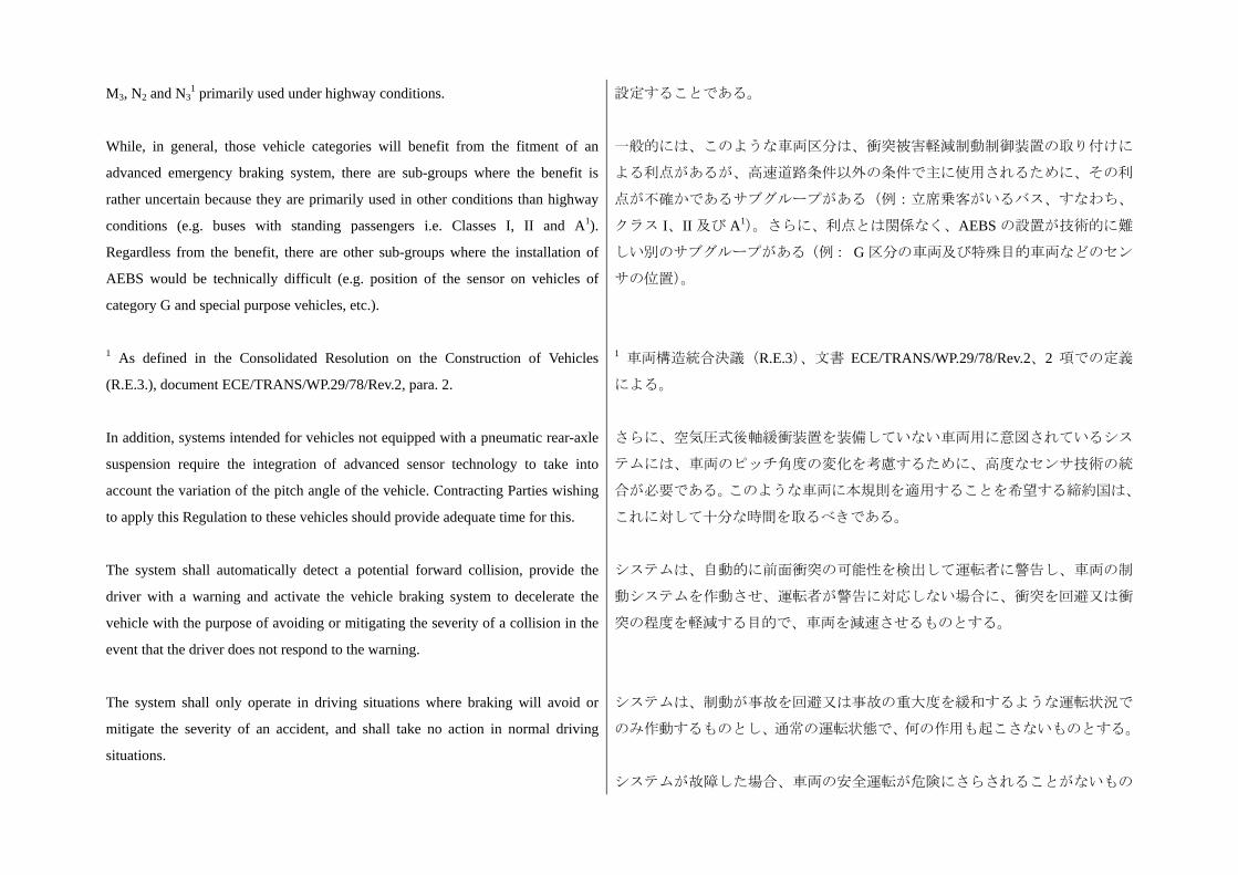
M3, N2 and N31 primarily used under highway conditions.
While, in general, those vehicle categories will benefit from the fitment of an
advanced emergency braking system, there are sub-groups where the benefit is
rather uncertain because they are primarily used in other conditions than highway
conditions (e.g. buses with standing passengers i.e. Classes I, II and A1).
Regardless from the benefit, there are other sub-groups where the installation of
AEBS would be technically difficult (e.g. position of the sensor on vehicles of
category G and special purpose vehicles, etc.).
1 As defined in the Consolidated Resolution on the Construction of Vehicles
(R.E.3.), document ECE/TRANS/WP.29/78/Rev.2, para. 2.
In addition, systems intended for vehicles not equipped with a pneumatic rear-axle
suspension require the integration of advanced sensor technology to take into
account the variation of the pitch angle of the vehicle. Contracting Parties wishing
to apply this Regulation to these vehicles should provide adequate time for this.
The system shall automatically detect a potential forward collision, provide the
driver with a warning and activate the vehicle braking system to decelerate the
vehicle with the purpose of avoiding or mitigating the severity of a collision in the
event that the driver does not respond to the warning.
The system shall only operate in driving situations where braking will avoid or
mitigate the severity of an accident, and shall take no action in normal driving
situations.
設定することである。
一般的には、このような車両区分は、衝突被害軽減制動制御装置の取り付けに
よる利点があるが、高速道路条件以外の条件で主に使用されるために、その利
点が不確かであるサブグループがある(例:立席乗客がいるバス、すなわち、
クラス I、II 及び A1)。さらに、利点とは関係なく、AEBS の設置が技術的に難
しい別のサブグループがある(例: G 区分の車両及び特殊目的車両などのセン
サの位置)。
1 車両構造統合決議(R.E.3)、文書 ECE/TRANS/WP.29/78/Rev.2、2 項での定義
による。
さらに、空気圧式後軸緩衝装置を装備していない車両用に意図されているシス
テムには、車両のピッチ角度の変化を考慮するために、高度なセンサ技術の統
合が必要である。このような車両に本規則を適用することを希望する締約国は、
これに対して十分な時間を取るべきである。
システムは、自動的に前面衝突の可能性を検出して運転者に警告し、車両の制
動システムを作動させ、運転者が警告に対応しない場合に、衝突を回避又は衝
突の程度を軽減する目的で、車両を減速させるものとする。
システムは、制動が事故を回避又は事故の重大度を緩和するような運転状況で
のみ作動するものとし、通常の運転状態で、何の作用も起こさないものとする。
システムが故障した場合、車両の安全運転が危険にさらされることがないもの
In the case of a failure in the system, the safe operation of the vehicle shall not be
endangered.
The system shall provide as a minimum an acoustic or haptic warning, which may
also be a sharp deceleration, so that an inattentive driver is made aware of a critical
situation.
During any action taken by the system (the warning and emergency braking
phases), the driver can, at any time through a conscious action, e.g. by a steering
action or an accelerator kick-down, take control and override the system.
The Regulation cannot include all the traffic conditions and infrastructure features
in the type-approval process. Actual conditions and features in the real world
should not result in false warnings or false braking to the extent that they
encourage the driver to switch the system off.
とする。
システムは、不注意な運転者が緊急事態に気付くように、 低でも、聴覚又は
触覚の警告をするものとし、急速な減速ともなりうる。
システムによる措置が講じられている間(警告と緊急制動段階)、運転者は、た
とえば、かじ取操作やアクセルのキックダウンのような意識行動を通じて随時、
システムを制御し、作動しないようにすることができる。
本規則は、すべての交通条件やインフラ機能を型式認可プロセスに含めること
はできない。現実の条件と機能は、運転者にシステムをオフに切り替えさせる
ような誤った警告や誤った制動をもたらさないようにすべきものとする。
1. Scope and purpose
This Regulation applies to the approval of vehicles of category M2, N2, M3 and N31
with regard to an on-board system to avoid or mitigate the severity of a rear-end in
lane collision. 1 As defined in the Consolidated Resolution on the Construction of Vehicles
(R.E.3.), document ECE/TRANS/WP.29/78/Rev.2, para. 2.
(a)N2 above 8 tons,
(b) M3 and
(c) N3.
Equipped with a pneumatic or air over hydraulic braking system with regard to an
on-board system to avoid or mitigate the severity of a rear-end in lane collision.
1. 適用範囲と目的
本規則は、車線での追突を回避又は重大度を緩和するための搭載システムに関
して、車両区分 M2、N2、M3及び N31の車両の認可に適用する。
1 車両構造統合決議(R.E.3)、文書 ECE/TRANS/WP.29/78/Rev.2、2 項の定義に
よる。
(a) 8 トンを超える N2、
(b) M3 及び
(c) N3。
車線での追突を回避又はその重大度を緩和するための搭載システムに関して、
空気圧式又は空気圧液圧複合式制動システムを備えているもの。
2. Definitions
2.1.
"Advanced Emergency Braking System (AEBS)" means a system which can
automatically detect a potential forward collision and activate the vehicle braking
system to decelerate the vehicle with the purpose of avoiding or mitigating a
collision.
2. 定義
2.1.
「衝突被害軽減制動制御装置(AEBS)」とは、自動的に前面衝突の可能性を検
出して、車両の制動システムを作動させ、衝突を回避又は軽減する目的で、車
両を減速させるシステムをいう。
2.2.
"Vehicle type with regard to its Advanced Emergency Braking System" means a
category of vehicles which do not differ in such essential respects as:
(a) The manufacturer's trade name or mark;
(b) Vehicle features which significantly influence the performances of the
Advanced Emergency Braking System;
(c) The type and design of the Advanced Emergency Braking System.
2.2.
「衝突被害軽減制動制御装置に係る車両型式」とは、以下のような本質的な観
点において差異のない車両の分類上の区分をいう。
(a) メーカーの商号又は商標、
(b) 衝突被害軽減制動制御装置の性能に著しい影響を及ぼす車両の機能、
(c) 衝突被害軽減制動制御装置の方式及び設計。
2.3.
"Subject vehicle" means the vehicle being tested.
2.4.
"Target" means a high volume series production passenger car of category M1 AA
saloon1 or in the case of a soft target an object representative of such a vehicle in
terms of its detection characteristics applicable to the sensor system of the AEBS
under test. 1 As defined in the Consolidated Resolution on the Construction of Vehicles
(R.E.3.), document ECE/TRANS/WP.29/78/Rev.2, para. 2.
2.3.
「被験車両」とは、試験されている車両をいう。
2.4.
「ターゲット」とは、M1 AA 区分のセダン 1の量産乗用車をいい、また、ソフ
トターゲットの場合は、試験中の AEBS のセンサシステムに適用される検出特
性という観点から、かかる車両を代表する目標物をいう。 1 車両構造統合決議(R.E.3)、文書 ECE/TRANS/WP.29/78/Rev.2、2 項での定義
による。
2.5.
"Moving target" means a target travelling at a constant speed in the same direction
and in the centre of the same lane of travel as the subject vehicle.
2.6.
"Stationary target" means a target at standstill facing the same direction and
2.5.
「移動ターゲット」とは、被験車両と同じ方向及び同じ走行車線の中央におい
て一定速度で走行するターゲットをいう。
2.6.
「静止ターゲット」とは、被験車両と同じ方向を向き、かつ同じ試験走行車線
positioned on the centre of the same test lane of travel as the subject vehicle. の中央に配置された、停止状態のターゲットをいう。
2.7.
"Soft target" means a target that will suffer minimum damage and cause minimum
damage to the subject vehicle in the event of a collision.
2.8.
"Collision warning phase" means the phase directly preceding the emergency
braking phase, during which the AEBS warns the driver of a potential forward
collision.
2.7.
「ソフトターゲット」とは、衝突時に 小限の損傷を被り、被験車両に対して
小限の損傷をもたらすターゲットをいう。
2.8.
「衝突警告段階」とは、AEBS が運転者に前面衝突の可能性を警告する、緊急
制動段階の直前の段階をいう。
2.9.
"Emergency braking phase" means the phase starting when the AEBS emits a
braking demand for at least 4 m/s2 deceleration to the service braking system of the
vehicle.
2.9.
「緊急制動段階」とは、AEBS が車両の常用制動システムに対し少なくとも 4
m/s2の減速の制動要求を発するときに開始する段階をいう。
2.10.
"Common space" means an area on which two or more information functions (e.g.
symbol) may be displayed, but not simultaneously.
2.11.
"Self-check" means an integrated function that checks for a system failure on a
semi-continuous basis at least while the system is active.
2.12.
"Time to collision (TTC)" means the value of time obtained by dividing the
distance between the subject vehicle and the target by the relative speed of the
subject vehicle and the target, at an instant in time.
2.10.
「共有領域」とは、2 つ以上の情報機能(たとえば記号)を、同時ではないが
表示することができる領域をいう。
2.11.
「セルフチェック」とは、少なくともシステムの作動中、半連続的にシステム
故障のチェックを行う統合機能をいう。
2.12.
「衝突余裕時間(TTC)」とは、ある瞬間の被験車両とターゲット間の距離を被
験車両とターゲットの相対速度で割ることにより得られる時間の値をいう。
3. Application for approval
3.1.
3. 認可申請
3.1.
The application for approval of a vehicle type with regard to the Advanced
Emergency Braking System shall be submitted by the vehicle manufacturer or by
his authorized representative.
衝突被害軽減制動制御装置に係る車両型式の認可申請は、車両メーカー又は正
規の委任代理人が提出するものとする。
3.2.
It shall be accompanied by the documents mentioned below in triplicate:
3.2.1.
A description of the vehicle type with regard to the items mentioned in paragraph
2.2., together with a documentation package which gives access to the basic design
of the AEBS and the means by which it is linked to other vehicle systems or by
which it directly controls output variables. The numbers and/or symbols identifying
the vehicle type shall be specified.
3.2.
それには、下記の文書を 3 部添付するものとする。
3.2.1.
2.2 項で言及されている項目に関する車両型式の説明に、AEBS の基本設計並び
に本システムをその他の車両システムに接続するための手段、又は出力変数を
直接制御するための手段を入手することができる文書パッケージを添付したも
の。車両型式を識別する数字及び/又は記号を指定するものとする。
3.3.
A vehicle representative of the vehicle type to be approved shall be submitted to
the Technical Service conducting the approval tests.
3.3.
認可対象の車両型式の代表的な車両を、認可試験を実施する技術機関に提出す
るものとする。
4. Approval
4.1.
If the vehicle type submitted for approval pursuant to this Regulation meets the
requirements of paragraph 5. below, approval of that vehicle shall be granted.
4.2.
An approval number shall be assigned to each type approved; its first two digits (at
present 01 corresponding to the 01 series of amendments) shall indicate the series
of amendments incorporating the most recent major technical amendments made to
the Regulation at the time of issue of the approval. The same Contracting
Party shall not assign the same number to the same vehicle type equipped with
another type of AEBS, or to another vehicle type.
4. 認可
4.1.
本規則に従って認可を求めるために提出される車両型式が、下記の 5 項の要件
を満たす場合、その車両の認可が付与されるものとする。
4.2.
認可番号は、認可された型式毎に割り当てられるものとし、認可番号の 初の
2 桁(現在のところ、第 1 改訂版に対応する「01」)は、認可発行時点において
本規則に 新の主要な技術的改訂を組み込んだ改訂版を示すものとする。同一
締約国において、別の型式の AEBS を備えている同一車両型式に、又は別の車
両型式に、同じ番号を割り当てないものとする。
4.3. 4.3.
Notice of approval or of refusal or withdrawal of approval pursuant to this
Regulation shall be communicated to the Parties to the Agreement which apply this
Regulation by means of a form conforming to the model in Annex 1 and
documentation supplied by the applicant being in a format not exceeding A4 (210
x297 mm), or folded to that format, and on an appropriate scale or electronic
format.
本規則に係る認可、又は認可の拒否、又は認可の取消の通知は、附則 1 のひな
形に適合する書式と、A4 版(210×297 mm)を超えないか、又は A4 版に折り畳
んだ状態で、適切な縮尺又は電子的形式で申請者によって提供される文書によ
って、本規則を適用している協定締約国に通知するものとする。
4.4.
There shall be affixed, conspicuously and in a readily accessible place specified on
the approval form, to every vehicle conforming to a vehicle type approved under
this Regulation, an international approval mark conforming to the model described
in Annex 2, consisting of:
4.4.
本規則の下で認可された車両型式に一致するすべての車両において、認可書式
で指定されていて近づきやすい目立つ場所に、附則 2 で説明されているひな形
に従った国際認可マークを付けるものとする。それは以下で構成されている。
4.4.1.
A circle surrounding the letter "E" followed by the distinguishing number of the
country which has granted approval;2 2 The distinguishing numbers of the Contracting Parties to the 1958 Agreement are
reproduced in Annex 3 to the Consolidated Resolution on the Construction of
Vehicles (R.E.3),
document ECE/TRANS/WP.29/78/Rev.2/Amend.3 -
www.unece.org/trans/main/wp29/wp29wgs/wp29gen/wp29resolutions.html
4.4.1.
文字「E」の後に、認可を付与した国の識別番号を記載し、その全体を円で囲ん
だもの、2 2 1958 年協定の締約国の識別番号は、車両構造統合決議(R.E.3)の附則 3、文
書 ECE/TRANS/WP.29/78/Rev.2/Amend.3
-www.unece.org/trans/main/wp29/wp29wgs/wp29gen/wp29resolutions.html に再録さ
れている。
4.4.2.
The number of this Regulation, followed by the letter "R", a dash and the approval
number to the right of the circle prescribed in paragraph 4.4.1. above.
4.4.2.
上記 4.4.1 項で説明されている円の右側に、本規則の番号、文字「R」、ダッシュ、
及び認可番号が続く。
4.5.
If the vehicle conforms to a vehicle type approved under one or more other
Regulations, annexed to the Agreement, in the country which has granted approval
under this Regulation, the symbol prescribed in paragraph 4.4.1. above need not be
repeated; in such a case, the Regulation and approval numbers and the additional
4.5.
車両が、協定に付属している 1 つ以上のその他の規則に基づいて認可された車
両型式に適合する場合、本規則の下で認可を付与した国においては、上記 4.4.1
項で説明されている記号は、繰り返す必要はない。そのような場合、規則及び
認可番号と追加記号は、上記 4.4.1 項で説明されている記号の右側に縦に並べて
symbols shall be placed in vertical columns to the right of the symbol prescribed in
paragraph 4.4.1. above.
配置するものとする。
4.6.
The approval mark shall be clearly legible and be indelible.
4.7.
The approval mark shall be placed close to or on the vehicle data plate.
4.6.
認可マークは明確に判読でき、かつ消えないものとする。
4.7.
認可マークは、車両データプレートの近くか、プレート上に貼付するものとす
る。
5. Specifications
5.1. General
5.1.1.
Any vehicle equipped with an AEBS complying with the definition of paragraph
2.1. shall meet the performance requirements contained in paragraphs 5.1. to 5.6.2.
of this Regulation and shall be equipped with an anti-lock braking function in
accordance with the performance requirements of Annex 13 of Regulation No.13."]
[This amendment is necessary only if the alternative drafting for paragraph 5.1.1.
in ECE/TRANS/WP.29/2011/92/Amend.1 is adopted]
5. 仕様
5.1. 一般要件
5.1.1.
2.1 項の定義に適合する AEBS を取り付けた車両は、本規則の 5.1 項から 5.6.2
項に含まれている性能要件を満たすものとし、協定規則第 13 号の附則 13 の性
能要件に従ったアンチロック制動機能を備えるものとする。この改訂は、
ECE/TRANS/WP.29/2011/92/Amend.1の5.1.1項に対する代替のドラフトが採用さ
れる場合のみ必要である。
5.1.2.
The effectiveness of the AEBS shall not be adversely affected by magnetic or
electrical fields. This shall be demonstrated by compliance with Regulation No.10,
03 Series of amendments to the Regulation.
5.1.2.
AEBS の有効性は、磁界又は電界による悪影響を受けないものとする。これは、
協定規則第 10 号、第 3 改訂版への適合により証明するものとする。
5.1.3.
Conformity with the safety aspects of complex electronic control systems shall be
shown by meeting the requirements of Annex 4.
5.2. Performance requirements
5.1.3.
複合型電子制御システムの安全要素に対する適合は、附則 4 の要件を満たすこ
とにより示すものとする。
5.2. 性能要件
5.2.1.
The system shall provide the driver with appropriate warning(s) as below:
5.2.1.
システムは、運転者に対し、以下のように適切な警告を出すものとする。
5.2.1.1.
A collision warning when the AEBS has detected the possibility of a collision with
a preceding vehicle of category M, N or O in the same lane which is travelling at a
slower speed, has slowed to a halt or is stationary having not being identified as
moving. The warning shall be as specified in paragraph 5.5.1.above
5.2.1.2.
A failure warning when there is a failure in the AEBS that prevents the
requirements of this Regulation of being met. The warning shall be as specified in
paragraph 5.5.4. below.
5.2.1.1.
同一車線にいる M、N 又は O 区分の先行車両のうち、より低速で走行中の車両、
減速して停止した車両、又は移動が確認されなかった静止車両との衝突の可能
性を AEBS が検出したときの衝突警告。警告は下記 5.5.1 項に規定されている通
りとする。
5.2.1.2.
AEBS に本規則の要件を満たすことが妨げられる故障があるときの故障警告。
警告は、下記 5.5.4 項に規定されている通りとする。
5.2.1.2.1.
There shall not be an appreciable time interval between each AEBS self-check, and
subsequently there shall not be an appreciable delay in illuminating the warning
signal, in the case of an electrically detectable failure.
5.2.1.2.1.
電気的に検出可能な故障の場合、AEBS による各セルフチェックの合間に感知
できるほどの時間間隔がないものとし、これに続く警告信号の点灯に感知でき
るほどの遅延がないものとする。
5.2.1.3.
A deactivation warning, if the vehicle is equipped with a means to manually
deactivate the AEBS, shall be given when the system is deactivated. This shall be
as specified in paragraph 5.4.2. below.
5.2.1.3.
AEBS を手動で無効化する手段が車両に備わっている場合には、システムが無
効化されたときに無効化警告が出されるものとする。これは、下記 5.4.2 項に規
定された通りとする。
5.2.2.
Subsequent to the warning(s) of paragraph 5.2.1.1. above, and subject to the
provisions of paragraphs 5.3.1. to 5.3.3. below, there shall be an emergency
braking phase having the purpose of significantly decreasing the speed of the
subject vehicle. This shall be tested in accordance with paragraphs 6.4. and 6.5. of
this Regulation.
5.2.2.
上記 5.2.1.1 項の警告に続き、また、下記 5.3.1 項から 5.3.3 項の規定を条件とし
て、被験車両の速度を著しく低下させる目的を有する緊急制動段階があるもの
とする。これは、本規則の 6.4 項及び 6.5 項に従って試験するものとする。
5.2.3.
The system shall be active at least within the vehicle speed range of 15 km/h up to
the maximum design speed of the vehicle, and at all vehicle load conditions, unless
manually deactivated as per paragraph 5.4. below.
5.2.3.
システムは、少なくとも 15 km/h から当該車両の 大設計速度までの車両速度
範囲内で、かつすべての車両負荷条件において機能するものとする。ただし、
下記 5.4 項に従って手動で無効化された場合は除く。
5.2.4.
The system shall be designed to minimize the generation of collision warning
signals and to avoid autonomous braking in situations where the driver would not
recognize an impending forward collision. This shall be demonstrated in
accordance with paragraph 6.8. of this Regulation.
5.2.4.
システムは、衝突警告信号の発生を 小限にし、かつ差し迫った前面衝突を運
転者が認識しない事態における自律制動を回避するように設計するものとす
る。これは、本規則の 6.8 項に従って証明するものとする。
5.3. Interruption by the driver
5.3.1.
The AEBS may provide the means for the driver to interrupt the collision warning
phase. However, when a vehicle braking system is used to provide a haptic
warning, the system shall provide the driver with a means to interrupt the warning
braking.
5.3. 運転者による中断
5.3.1.
AEBS は、運転者に衝突警告段階の中断手段を提供してもよい。ただし、車両
制動システムを用いて触覚警告を出すときは、当該システムは運転者に、警告
制動を中断する手段を提供するものとする。
5.3.2.
The AEBS shall provide the means for the driver to interrupt the emergency
braking phase.
5.3.2.
AEBS は、運転者による緊急制動段階の中断手段を提供するものとする。
5.3.3.
In both cases above, this interruption may be initiated by any positive action (e.g.
kick-down, operating the direction indicator control) that indicates that the driver is
aware of the emergency situation. The vehicle manufacturer shall provide a list of
these positive actions to the technical service at the time of type approval and it
shall be annexed to the test report.
5.4.
When a vehicle is equipped with a means to deactivate the AEBS function, the
following conditions shall apply as appropriate:
5.4.1.
The AEBS function shall be automatically reinstated at the initiation of each new
ignition cycle.
5.4.2.
5.3.3.
上記の 5.3.1 項及び 5.3.2 項の両方の場合においては、運転者が緊急事態に気付
いていることを示す積極的な行為(例:キックダウン、方向指示器の操作)に
よって、中断を起こすことができる。車両メーカーは、型式認可時にこれらの
積極的な行為のリストを技術機関に提供するものとし、これを試験成績書に添
付するものとする。
5.4.
車両に AEBS 機能を無効化する手段が備わっている場合には、必要に応じて以
下の条件を適用するものとする。
5.4.1.
AEBS 機能は、新しいイグニッション(始動)サイクルの開始の都度、自動的
に復帰するものとする。
5.4.2.
A constant optical warning signal shall inform the driver that the AEBS function
has been deactivated. The yellow warning signal specified in paragraph 5.5.4.
below may be used for this purpose.
光学警告信号を点灯し続けることによって、運転者に対し AEBS 機能が無効化
されたことを知らせるものとする。この目的のために、下記 5.5.4 項に規定され
ている黄色の警告信号を使用してもよいものとする。
5.5. Warning indication
5.5.1.
The collision warning referred to in paragraph 5.2.1.1. above shall be provided by
at least two modes selected from acoustic, haptic or optical. The timing of the
warning signals shall be such that they provide the possibility for the driver to react
to the risk of collision and take control of the situation, and shall also avoid
nuisance for the driver by too early or too frequent warnings. This shall be tested in
accordance with the provisions of paragraphs 6.4.2. and 6.5.2. of this Regulation
5.5.2.
A description of the warning indication and the sequence in which the collision
warning signals are presented to the driver shall be provided by the vehicle
manufacturer at the time of type-approval and recorded in the test report.
5.5. 警告表示
5.5.1.
上記 5.2.1.1 項で言及されている衝突警告は、聴覚、触覚又は光学モードのうち
から選ばれた少なくとも 2 つのモードで提供するものとする。警告信号のタイ
ミングは、運転者が衝突のリスクに反応して事態をコントロールする可能性を
提供するようなものとし、また、早すぎる警告又は頻繁すぎる警告による運転
者への迷惑を回避するものとする。これは、本規則の 6.4.2 項及び 6.5.2 項の規
定に従って試験するものとする。
5.5.2.
車両メーカーは、型式認可時に、警告の表示並びに衝突警告信号が運転者に提
示される順序に関する説明を提出し、試験成績書に記録するものとする。
5.5.3.
Where an optical means is used as part of the collision warning, the optical signal
may be the flashing of the failure warning signal specified in paragraph 5.5.4.
below.
5.5.3.
衝突警告の一部として光学的手段を使用する場合、光学信号は、下記 5.5.4 項に
規定されている故障警告信号の点滅としてもよい。
5.5.4.
The failure warning referred to in paragraph 5.2.1.2. above shall be a constant
yellow optical warning signal.
5.5.4.
上記 5.2.1.2 項で言及されている故障警告は、黄色光学警告信号を点灯し続ける
ものとする。
5.5.5.
Each AEBS optical warning signal shall be activated either when the ignition
(start) switch is turned to the "on" (run) position or when the ignition (start) switch
is in a position between the "on" (run) and "start" that is designated by the
manufacturer as a check position (initial system (power-on)). This requirement
5.5.5.
各 AEBS 光学警告信号は、イグニッション(始動)スイッチが「オン」(走行)
位置になったとき、又はイグニッション(始動)スイッチがチェック位置(初
期システム(電源オン))としてメーカーから指定されている「オン」(走行)
と「スタート」の間の位置にあるときのいずれかに作動するものとする。この
does not apply to warning signals shown in a common space.
5.5.6.
The optical warning signals shall be visible even by daylight; the satisfactory
condition of the signals must be easily verifiable by the driver from the driver's
seat.
要件は、共有領域に示される警告信号には適用しない。
5.5.6.
光学警告信号は、昼光下でも視認できるものとする。この信号の満足のいく状
態とは、運転席にいる運転者から容易に確認できるものでなければならない。
5.5.7.
When the driver is provided with an optical warning signal to indicate that the
AEBS is temporarily not available, for example due to inclement weather
conditions, the signal shall be constant and yellow in colour. The failure warning
signal specified in paragraph 5.5.4. above may be used for this purpose.
5.5.7.
運転者に対し、例えば厳しい天候条件により、AEBS が一時的に利用できない
ことを示す光学警告信号が出される場合、信号は点灯し続けるものとし、黄色
とする。この目的のために、上記 5.5.4 項に規定されている故障警告信号を使用
してもよい。
5.6. Provisions for the periodic technical inspection
5.6.1.
At a periodic technical inspection it shall be possible to confirm the correct
operational status of the AEBS by a visible observation of the failure warning
signal status, following a "power-ON" and any bulb check. In the case of the
failure warning signal being in a common space, the common space must be
observed to be functional prior to the failure warning signal status check.
5.6.2.
At the time of type approval, the means to protect against simple unauthorized
modification of the operation of the failure warning signal chosen by the
manufacturer shall be confidentially outlined.
Alternatively, this protection requirement is fulfilled when a secondary means of
checking the correct operational status of the AEBS is available.
5.6. 定期技術検査に関する規定
5.6.1.
定期技術検査では「電源オン」及びバルブチェックの後、故障警告信号の状態
を目視で確認することにより AEBS の適正な作動状態を確認することが可能で
あるものとする。
共有領域にある故障警告信号の場合、故障警告信号の状態の確認に先立ち、共
有領域が機能していることが観察されなければならない。
5.6.2.
型式認可時、メーカーが選んだ故障警告信号の作動の簡単な不正改造に対する
保護手段は、機密として概要を説明するものとする。
あるいは、この保護要件は、AEBS の適正な作動状態を確認するための二次的
な手段がある場合に満たされる。
6. Test procedure
6.1. Test conditions
6. 試験手順
6.1. 試験条件
6.1.1.
The test shall be performed on a flat, dry concrete or asphalt surface affording good
adhesion.
6.1.2.
The ambient temperature shall be between 0 deg. C and 45 deg. C.
6.1.3.
The horizontal visibility range shall allow the target to be observed throughout the
test.
6.1.4.
The tests shall be performed when there is no wind liable to affect the results.
6.1.1.
試験は、良好な粘着が得られる平らで乾燥したコンクリート又はアスファルト
の路面で実施するものとする。
6.1.2.
周囲温度は、0℃から 45℃の間とする。
6.1.3.
水平方向の視認性の範囲は、試験全体を通してターゲットが観察できる範囲と
する。
6.1.4.
試験は、結果に影響を及ぼす可能性のある風がないときに実施するものとする。
6.2. Vehicle conditions
6.2.1. Test weight
The vehicle shall be tested in a condition of load to be agreed between the
manufacturer and the Technical Service. No alteration shall be made once the test
procedure has begun.
6.2. 車両条件
6.2.1. 試験重量
車両は、メーカーと技術機関の間で合意された積載条件で試験するものとする。
試験手順の開始後は一切の変更を行わないものとする。
6.3. Test targets
6.3.1.
The target used for the tests shall be a regular high volume series production
passenger car of category M1 AA saloon, or alternatively a "soft target"
representative of such a vehicle in terms of its identification characteristics
applicable to the sensor system of the AEBS under test.3 3 The identification characteristics of the soft target shall be agreed upon between
the Technical Service and the vehicle manufacturer as being equivalent to a
passenger car of category M1 AA saloon
6.3. 試験ターゲット
6.3.1.
試験に使用するターゲットは、M1 AA 区分セダンの通常の量産乗用車、あるい
は、試験中の AEBS のセンサシステムに適用される識別特性という観点から、
そのような車両を代表する「ソフトターゲット」とする。3 3 ソフトターゲットの識別特性は、区分 M1 AA セダンの乗用車と同等であると
して技術機関と車両メーカーの間で合意されたものとする。
6.3.2.
Details that enable the target(s) to be specifically identified and reproduced shall be
recorded in the vehicle type approval documentation.
6.3.2.
ターゲットを厳密に識別し、再現できる詳細情報は、車両型式認可文書に記録
するものとする。
6.4. Warning and activation test with a stationary target
6.4.1.
The subject vehicle shall approach the stationary target in a straight line for at least
two seconds prior to the functional part of the test with a subject vehicle to target
centreline offset of not more than 0.5 m.
The functional part of the test shall start when the subject vehicle is travelling at a
speed of 80 +/- 2 km/h and is at a distance of at least 120 m from the target. From
the start of the functional part until the point of collision there shall be no
adjustment to any control of the subject vehicle by the driver other than slight
adjustments to the steering control to counteract any drifting.
6.4. 静止ターゲットを用いた警告及び作動試験
6.4.1.
被験車両は、試験の機能的部分が開始する前の少なくとも 2 秒間、ターゲット
中心線に対する被験車両のずれが 0.5 m 以下となる状態で、静止ターゲットに
一直線に接近するものとする。
試験の機能的部分は、被験車両が 80 ± 2 km/h の速度で走行しており、ターゲッ
トからの距離が少なくとも 120 m であるときに開始するものとする。機能的部
分の開始から衝突点までの間、ドリフトを防ぐためのかじ取ハンドルへの若干
の調整を除き、運転者による被験車両の制御への調整はないものとする。
6.4.2.
The timing for the collision warning modes referred to in paragraph 5.5.1. above
shall comply with the following:
6.4.2.
上記 5.5.1 項で言及されている衝突警告モードのタイミングは、以下に適合する
ものとする。
6.4.2.1.
At least one warning mode shall be provided no later than specified in Table I
Column B of Annex 3.
In the case of the vehicles referred to in Table I, row 1 of Annex 3, the warning
shall be haptic or acoustic.
In the case of the vehicles referred to in Table I, row 2 of Annex 3, the warning
shall be haptic, acoustic or optical
6.4.2.2.
At least two warning modes shall be provided no later than specified in Table I
Column C of Annex 3.
6.4.2.3.
Any speed reduction during the warning phase, shall not exceed either 15 km/h or
30 per cent of the total subject vehicle speed reduction, whichever is higher.
6.4.2.1.
附則 3 の表 I の B 列に指定されている値までに、少なくとも 1 つの警告モード
を出すものとする。
附則 3 の表 I の行 1 に言及する車両の場合、当該警告は触覚又は聴覚によるも
のとする。
附則 3 の表 I の行 2 に言及する車両の場合、当該警告は触覚、聴覚又は視覚に
よるものとする。
6.4.2.2.
附則 3 の表 I の C 列に指定されている値までに、少なくとも 2 つの警告モード
を出すものとする。
6.4.2.3.
警告段階中の減速は、15 km/h 又は被験車両の総減速量の 30%のいずれか高い方
を超えないものとする。
6.4.3. 6.4.3.
The collision warning phase shall be followed by the emergency braking phase.
6.4.4.
The total speed reduction of the subject vehicle at the time of the impact with the
stationary target shall be not less than the value specified in Table I, column D of
Annex 3.
衝突警告段階の後に緊急制動段階が続くものとする。
6.4.4.
静止ターゲットとの衝突時における被験車両の総減速量は、附則 3 の表 I の D
列に指定されている値以上とする。
6.4.5.
The emergency braking phase shall not start before a TTC equal to or less than 3.0
seconds. Compliance shall be verified by either actual measurement during the test
or using documentation provided by the vehicle manufacturer, as agreed between
the Technical Service and the vehicle manufacturer.
6.5.
Warning and activation test with a moving target
6.4.5.
緊急制動段階は、TTC が 3.0 秒以下になってから開始するものとする。
技術機関と車両メーカーの合意に基づき、試験中に実際に測定を行うか、又は
車両メーカーにより提供された文書を使用して、適合を確認するものとする。
6.5.
移動ターゲットを用いた警告及び作動試験
6.5.1.
The subject vehicle and the moving target shall travel in a straight line, in the same
direction, for at least two seconds prior to the functional part of the test, with a
subject vehicle to target centreline offset of not more than 0.5m.
The functional part of the test shall start with the subject vehicle travelling at a
speed of 80 +/- 2 km/h, the moving target at speed of the value specified in Table I,
column H of Annex 3, and a separation distance of at least 120 m between them.
From the start of the functional part of the test until the subject vehicle comes to a
speed equal to that of the target there shall be no adjustment to any subject vehicle
control by the driver other than slight steering adjustments to counteract any
drifting.
6.5.2.
The timing for the collision warning modes referred to in paragraph 5.5.1. above
shall comply with the following:
6.5.1.
被験車両及び移動ターゲットは、試験の機能的部分が開始する前の少なくとも
2 秒間、ターゲット中心線に対する被験車両のずれが 0.5 m 以下となる状態で、
同一方向に一直線に走行するものとする。
試験の機能的部分は、被験車両が 80 ± 2 km/h の速度で走行しており、移動ター
ゲットが附則 3 の表 I の H 列に指定されている値の速度で走行して、それらの
間の車間距離は、少なくとも 120m のときに開始するものとする。
試験の機能的部分の開始から、被験車両がターゲットの速度と等しい速度に達
するまで、ドリフトを防ぐためのステアリングの若干の調整を除き、運転者に
よる被験車両の制御の調整はないものとする。
6.5.2.
上記 5.5.1 項で言及されている衝突警告モードのタイミングは、以下に適合する
ものとする。
6.5.2.1. 6.5.2.1.
At least one haptic or acoustic warning mode shall be provided no later than
specified in Table I Column E of Annex 3
6.5.2.2.
At least two warning modes shall be provided no later than specified in Table I
Column F of Annex 3.
6.5.2.3.
Any speed reduction during the warning phase shall not exceed either 15 km/h or
30 per cent of the total subject vehicle speed reduction, whichever is higher.
6.5.3.
The emergency braking phase shall result in the subject vehicle not impacting the
moving target.
6.5.4.
The emergency braking phase shall not start before a TTC equal to or less than 3.0
seconds.
Compliance shall be verified by either actual measurement during the test or using
documentation provided by the vehicle manufacturer, as agreed between the
Technical Service and the vehicle manufacturer.
附則 3 の表 I の E 列に指定されている値までに、少なくとも 1 つの触覚又は聴
覚警告モードを提供するものとする。
6.5.2.2.
附則 3 の表 I の F 列に指定されている値までに、少なくとも 2 つの警告モード
を提供するものとする。
6.5.2.3.
警告段階中の減速は、15 km/h 又は被験車両の総減速量の 30%のいずれか高い方
を超えないものとする。
6.5.3.
緊急制動段階は、被験車両が移動ターゲットに衝突しないようにするものとす
る。
6.5.4.
緊急制動段階は、TTC が 3.0 秒以下になってから開始するものとする。
技術機関と車両メーカーの合意に基づき、試験中に実際に測定を行うか、又は
車両メーカーにより提供された文書を使用して、適合を確認するものとする。
6.6. Failure detection test
6.6.1.
Simulate an electrical failure, for example by disconnecting the power source to
any AEBS component or disconnecting any electrical connection between AEBS
components. When simulating an AEBS failure, neither the electrical connections
for the driver warning signal of paragraph 5.5.4. above nor the optional manual
AEBS deactivation control of paragraph 5.4. shall be disconnected.
6.6.2.
The failure warning signal mentioned in paragraph 5.5.4. above shall be activated
and remain activated not later than 10 seconds after the vehicle has been driven at a
6.6. 故障検出試験
6.6.1.
例えば、AEBS 構成部品の電源を切断するか、AEBS 構成部品間の電気接続を切
断して、電気的故障を再現する。AEBS の故障を再現する際、上記 5.5.4 項の運
転者警告信号及び 5.4 項の光学式手動 AEBS 無効化制御の電気接続は、切断し
ないものとする。
6.6.2.
上記 5.5.4 項で言及されている故障警告信号は、再現された故障が存在する限
り、当該車両が 15 km/h を超える速度で運転されてから 10 秒以内に作動して、
speed greater than 15 km/h and be reactivated immediately after a subsequent
ignition "off" ignition "on" cycle with the vehicle stationary as long as the
simulated failure exists.
作動したままとなり、その後の車両静止状態におけるイグニッション「オフ」
イグニッション「オン」サイクル後に直ちに再作動するものとする。
6.7. Deactivation test
6.7.1.
For vehicles equipped with means to deactivate the AEBS, turn the ignition (start)
switch to the "on" (run) position and deactivate the AEBS. The warning signal
mentioned in paragraph 5.4.2. above shall be activated. Turn the ignition (start)
switch to the "off" position. Again, turn the ignition (start) switch to the "on" (run)
position and verify that the previously activated warning signal is not reactivated,
thereby indicating that the AEBS has been reinstated as specified in paragraph
5.4.1. above. If the ignition system is activated by means of a "key", the above
requirement shall be fulfilled without removing the key.
6.7. 無効化試験
6.7.1.
AEBS を無効化する手段が備わっている車両の場合は、イグニッション(始動)
スイッチを「オン」(走行)位置にして、AEBS を無効化する。上記 5.4.2 項で
言及されている警告信号が作動するものとする。イグニッション(始動)スイ
ッチを「オフ」位置にする。再度、イグニッション(始動)スイッチを「オン」
(走行)位置にして、これより前に作動していた警告信号が再作動しないこと
を確認する。これは、AEBS が上記 5.4.1 項で規定されている通りに復帰したこ
とを意味する。イグニッションシステムが「キー」により作動した場合、上記
の要件はキーを外さずに満たすものとする。
6.8. False reaction test
6.8.1.
Two stationary vehicles, of category M1 AA saloon, shall be positioned:
(a) So as to face in the same direction of travel as the subject vehicle,
(b) With a distance of 4.5 m between them4, 4 The point of reference of each stationary vehicle for establishing the distance
between the two stationary vehicles, shall be determined in accordance with ISO
612-1978.
(c) With the rear of each vehicle aligned with the other.
6.8. 誤反応試験
6.8.1.
車両区分 M1 AA のセダンである静止車両 2 台を以下の通りに配置するものとす
る。
(a) 被験車両と同じ走行方向を向いている。
(b) 両車両間の距離が 4.5 m である 4。 4 2 台の静止車両間の距離を設定するための各静止車両の基準点は、ISO
612-1978 に従って決定するものとする。
(c) 各車両の後部が一直線に並んでいる。
6.8.2.
The subject vehicle shall travel for a distance of at least 60 m, at a constant speed
of 50 +/- 2 km/h to pass centrally between the two stationary vehicles. During the
test there shall be no adjustment of any subject vehicle control other than slight
steering adjustments to counteract any drifting.
6.8.2.
被験車両は、2 台の静止車両間の中心を通過するように、50 ± 2 km/h の一定速
度で少なくとも 60 m の距離を走行するものとする。
試験中は、ドリフトを防ぐためのステアリングの若干の調整を除き、被験車両
の制御の調整はないものとする。
6.8.3.
The AEBS shall not provide a collision warning and shall not initiate the
emergency braking phase.
6.8.3.
AEBS は、衝突警告は出さないものとし、緊急制動段階を開始しないものとす
る。
7. Modification of vehicle type and extension of approval
7.1.
Every modification of the vehicle type as defined in paragraph 2.2. above shall be
notified to the Type Approval Authority which approved the vehicle type. The Type
Approval Authority may then either:
7.1.1.
Consider that the modifications made do not have an adverse effect on the
conditions of the granting of the approval and grant an extension of approval;
7. 車両型式の変更及び認可の拡大
7.1.
上記 2.2 項で定義されている車両型式のあらゆる変更は、車両型式を認可した
行政官庁に通知するものとする。行政官庁は以下のいずれかの処置をとること
ができる。
7.1.1.
実施される変更は、認可の付与の条件に悪影響を及ぼさないので、認可の拡大
を認めることを検討する。
7.1.2.
Consider that the modifications made affect the conditions of the granting of the
approval and require further tests or additional checks before granting an extension
of approval.
7.1.2.
実施される変更は、認可の付与の条件に影響するので、認可の拡大を認める前
に、追加の試験又は追加の検査を要求することを検討する。
7.2.
Confirmation or refusal of approval, specifying the alterations, shall be
communicated by the procedure specified in paragraph 4.3. above to the
Contracting Parties to the Agreement which apply this Regulation.
7.2.
認可の確認又は拒否は、変更点を明記して、上記 4.3 項に規定されている手順
によって、本規則を適用する協定締約国に通知するものとする。
7.3.
The Type Approval Authority shall inform the other Contracting Parties of the
extension by means of the communication form which appears in Annex 1 to this
Regulation. It shall assign a serial number to each extension, to be known as the
extension number.
7.3.
行政官庁は本規則の附則 1 にある通知書を使って、拡大について、他の締約国
に通知するものとする。当局は、各拡大に対し通し番号を割り当て、拡大番号
を通知するものとする。
8. Conformity of production 8. 生産の適合性
8.1.
Procedures concerning conformity of production shall conform to the general
provisions defined in Appendix 2 to the Agreement
(E/ECE/324-E/ECE/TRANS/505/Rev.2) and meet the following requirements:
8.2.
A vehicle approved pursuant to this Regulation shall be so manufactured as to
conform to the type approved by meeting the requirements of paragraph 5.
above;
8.1.
生産の適合性に関する手続きは、協定(E/ECE/324-E/ECE/TRANS/505/Rev.2)の
付録 2 で規定されている一般規定に準拠し、下記の要件を満たすものとする。
8.2.
本規則に従って認可された車両は、上記 5 項の要件を満たすことによって認可
された型式に適合するように製造するものとする。
8.3.
The Type Approval Authority which has granted approval may at any time verify
the conformity of control methods applicable to each production unit. The normal
frequency of such inspections shall be once every two years.
8.3.
認可を付与した行政官庁は、各生産施設に適用可能な管理方法の適合性を随時
検証できる。このような検証の通常の頻度は、2 年毎に 1 回とする。
9. Penalties for non-conformity of production
9.1.
The approval granted in respect of a vehicle type pursuant to this Regulation may
be withdrawn if the requirements laid down in paragraph 8. above are not complied
with.
9.2.
If a Contracting Party withdraws an approval it had previously granted, it shall
forthwith so notify the other Contracting Parties applying this Regulation by
sending them a communication form conforming to the model in Annex 1 to this
Regulation.
9. 生産の不適合に対する罰則
9.1.
本規則に従って車両型式に関して付与した認可は、上記 8 項に規定されている
要件が順守されていない場合、取り消すことができる。
9.2.
以前に付与した認可を締約国が取り消す場合、本規則を適用する他の締約国に
対して、本規則の附則 1 にあるひな形に適合する通知書を送ることによって、
速やかにその旨を通知するものとする。
10. Production definitively discontinued
If the holder of the approval completely ceases to manufacture a type of vehicle
approved in accordance with this Regulation, he shall so inform the Type Approval
10. 生産中止
認可の保有者が、本規則に従って認可された車両型式の製造を完全に中止する
場合には、その認可を付与した行政官庁にその旨を通知するものとする。当該
Authority which granted the approval, which in turn shall forthwith inform the
other Contracting Parties to the Agreement applying this Regulation by means of a
communication form conforming to the model in Annex 1 to this Regulation.
当局は、本規則を適用する他の協定締約国に対し、本規則の附則 1 に示すひな
形に準拠する通知書によって、速やかにその旨を通知するものとする。
11. Names and addresses of the Technical Services responsible for conducting
approval tests and of Type Approval Authorities
The Contracting Parties to the Agreement applying this Regulation shall
communicate to the United Nations Secretariat the names and addresses of the
Technical Services responsible for conducting approval tests and of the Type
Approval Authorities which granted approval and to which forms certifying
approval or extension or refusal or withdrawal of approval are to be sent.
11. 認可試験の実施を担当する技術機関と行政官庁の名称と所在地
本規則を適用する協定締約国は、認可試験の実施を担当する技術機関の名称と
所在地、並びに認可を付与し、また、認可、認可の拡大、拒否又は取消の証明
書の送付先となる行政官庁の名称と所在地を、国連事務局に通知するものとす
る
12. Transitional provisions 12. 過渡規定
12.1. As from the official date of entry into force of the 01 series of amendments,
no Contracting Party applying the 01 series of amendments to this Regulation, shall
refuse to grant type Approvals in accordance with the 01 series of amendments of
this Regulation.
12.1. 第 1 改訂版の正式発効日以後、本規則の第 1 改訂版を適用するどの締約国
も、本規則の第 1 改訂版に従って型式認可の付与を拒否しないものとする。
12.2. As from the date of into force of the 01 series of amendments to this
Regulation, Contracting Parties applying this Regulation may continue granting
type approvals and extensions of type approvals to the 00 series of amendments to
this Regulation.
In accordance with Article 12 of the 1958 Agreement, the 00 series of amendments
may be used as an alternative to the 01 series. Contracting Parties shall notify to
the Secretariat General which alternative they apply. In the absence of notification
of Contracting Parties to the Secretariat General, Contracting Parties will be
considered to apply the 01 series.
12.2. 本規則の第 1 改訂版の正式発効日以後、本規則を適用する締約国は引き続
き、本規則への第 0 改訂版に対し、型式認可の付与と、型式認可の拡大を認め
てもよい。
1958 年協定の第 12 条に従い、第 0 改訂版は、第 1 改訂版の代替として使用し
てもよい。締約国は、事務総局に、どの代替を適用するかを通知するものとす
る。締約国から事務総局への通知がないと、締約国は第 1 改訂版を適用すると
みなされる。
12.3. As from the date of entry into force of the 01 series of amendments, no 12.3. 第 1 改訂版の正式発効日以後、本規則を適用するどの締約国も、本規則へ
Contracting Party applying this Regulation shall refuse national or regional type
approval of a vehicle type approved to the 01 series of amendments to this
Regulation.
の第 1 改訂版に対して認可された車両型式に関する国又は地域の型式認可を拒
否しないものとする。
12.4. Until 1 November 2016, no Contracting Party applying this Regulation shall
refuse national or regional type approval of a vehicle type approved to the 00 series
of amendments to this Regulation.
12.4. 2016 年 11 月 1 日まで、本規則を適用するどの締約国も本規則への第 0 改
訂版に対して認可された車両型式に関する国又は地域の型式認可を拒否しない
ものとする。
12.5. As from 1 November 2016, Contracting Parties applying the 01 series of
amendments to this Regulation shall not be obliged to accept, for the purpose of
national or regional type approval, a vehicle type approved to the 00 series of
amendments to this Regulation.
12.5. 2016 年 11 月 1 日以後、本規則に第 1 改訂版を適用する締約国は、国又は
地域の型式認可のために、本規則への第 0 改訂版に対して認可された車両型式
を受け入れる義務はないものとする。
Annex 1
Communication
(Maximum format: A4 (210 x 297 mm))
issued by : Name of administration:
......................................
......................................
......................................
附則 1
通知
( 大 A4 版(210×297 mm))
発行:行政官庁名
......................................
......................................
......................................
1Distinguishing number of the country which has
granted/extended/refused/withdrawn an approval (see approval provisions in the
Regulation).
Concerning:2 2 Delete what does not apply.
1 認可を付与/拡大/拒否/取消した国の識別番号(本規則の認可規定を参
照)。
協定規則第 131 号に基づく、衝突被害軽減制動制御装置に関する車両型式の
認可付与
認可拡大
Approval granted
Approval extended
Approval refused
Approval withdrawn
Production definitively discontinued
of a type of vehicle with regard to the advanced emergency braking system
pursuant to Regulation No. 131
Approval No.:
Extension No.
認可拒否
認可取消
生産中止
について 2 2 該当しないものを抹消する。
認可番号
拡大番号
1. Trademark:
2. Type and trade name(s):
3. Name and address of manufacturer:
4. If applicable, name and address of manufacturer's representative:
5. Brief description of vehicle:
6. Data to enable the identification of the type of AEBS:
7. Date of submission of vehicle for approval:
8. Technical Service performing the approval tests:
9. Date of report issued by that Service:
10. Number of report issued by that Service:
11. Approval with regard to the AEBS is granted/refused:2 2 Delete what does not apply.
12. Place:
13. Date:
14. Signature:
15. Annexed to this communication are the following documents, bearing the
approval number indicated above:
List of the positive actions enabling the driver to interrupt the braking phase
1. 商標
2. 型式と商品名
3. メーカーの名称及び所在地
4. 該当する場合、メーカーの代理人の名称及び所在地
5. 車両の簡単な説明
6. AEBS の型式の識別を可能にするデータ
7. 認可用の車両の提出日
8. 認可試験を実施する技術機関
9. その技術機関によって発行される試験成績書発行日
10. その技術機関によって発行される試験成績書番号
11. AEBS に関連した認可の付与/拒否 2 2 該当しないものを抹消する。
12. 場所
13. 日付
14. 署名
15. 上記の認可番号を有する下記の文書を本通知書に添付する。
運転者が制動段階を中断するのを可能にする積極的な行為のリスト
AEBS 警告ストラテジーの説明
Description of the AEBS warning strategy
Details which enable the targets to be specifically identified
16. Any remarks:
ターゲットを特別に識別できるようにする詳しい説明
16. 備考
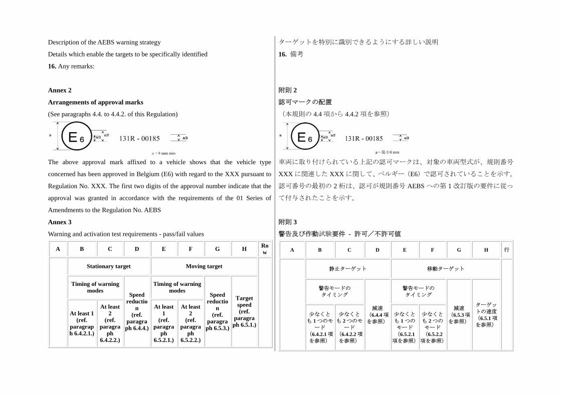
Annex 2
Arrangements of approval marks
(See paragraphs 4.4. to 4.4.2. of this Regulation)
The above approval mark affixed to a vehicle shows that the vehicle type
concerned has been approved in Belgium (E6) with regard to the XXX pursuant to
Regulation No. XXX. The first two digits of the approval number indicate that the
approval was granted in accordance with the requirements of the 01 Series of
Amendments to the Regulation No. AEBS
附則 2
認可マークの配置
(本規則の 4.4 項から 4.4.2 項を参照)
車両に取り付けられている上記の認可マークは、対象の車両型式が、規則番号
XXX に関連した XXX に関して、ベルギー(E6)で認可されていることを示す。
認可番号の 初の 2 桁は、認可が規則番号 AEBS への第 1 改訂版の要件に従っ
て付与されたことを示す。
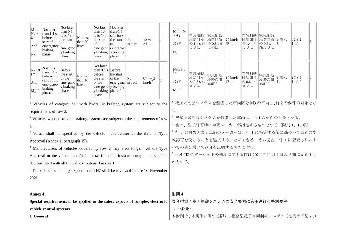
Annex 3
Warning and activation test requirements - pass/fail values
A B C D E F G H Row
Stationary target Moving target
Timing of warning modes
Speed reductio
n (ref.
paragraph 6.4.4.)
Timing of warning modes
Speed reductio
n (ref.
paragraph 6.5.3.)
Target speed(ref.
paragraph 6.5.1.)
At least 1(ref.
paragraph 6.4.2.1.)
At least 2
(ref. paragra
ph 6.4.2.2.)
At least 1
(ref. paragra
ph 6.5.2.1.)
At least 2
(ref. paragra
ph 6.5.2.2.)
附則 3
警告及び作動試験要件 - 許可/不許可値
A B C D E F G H 行
静止ターゲット 移動ターゲット
警告モードの タイミング
減速 (6.4.4 項
を参照)
警告モードの タイミング
減速 (6.5.3項を参照)
ターゲッ
トの速度
(6.5.1 項
を参照)
少なくと
も 1 つのモ
ード (6.4.2.1 項
を参照)
少なくと
も 2 つのモ
ード (6.4.2.2 項
を参照)
少なくと
も 1 つの
モード
(6.5.2.1項を参照)
少なくと
も 2 つの
モード
(6.5.2.2項を参照)
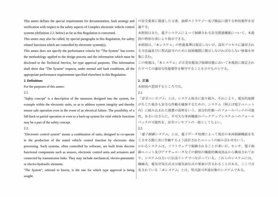
M31,
N2 > 8 t And N3
Not later than 1.4 s. before the start of emergency braking phase
Not later than 0.8 s. before the start of emergency braking phase
Not less than 20 km/h
Not later than 1.4 s. before the start of emergency braking phase
Not later than 0.8 s. before the start of emergency braking phase
No impact
12 +/- 2 km/h 1
N2< 8 t 2, 4 And M2
2, 4
Not later than 0.8 s before the start of the emergency braking phase
Before the start of the emergency braking phase 3
Not less than 10 km/h
Not later than 0.8 s before the start of the emergency braking phase
Before the start of the emergency braking phase 3
No impact
67 +/- 2 km/h 5 2
1 Vehicles of category M3 with hydraulic braking system are subject to the
requirements of row 2. 2 Vehicles with pneumatic braking systems are subject to the requirements of row
1. 3 Values shall be specified by the vehicle manufacturer at the time of Type
Approval (Annex 1, paragraph 15). 4 Manufacturers of vehicles covered by row 2 may elect to gain vehicle Type
Approval to the values specified in row 1; in this instance compliance shall be
demonstrated with all the values contained in row 1. 5 The values for the target speed in cell H2 shall be reviewed before 1st November
2021.
M31、N2
> 8 t 及び N3
緊急制動段階開始の 1.4 s 前までに
緊急制動段階開始の 0.8 s 前までに
20 km/h以上
緊急制動段階開始の1.4 s前までに
緊急制動段階開始の 0.8 s前までに
影響なし
12 ± 2 km/h 1
N2≦8 t 2,4 及び M2
2,4
緊急制動段階開始の 0.8 s 前までに
緊急制動段階の開始前 3
10 km/h以上
緊急制動段階開始の0.8 s前までに
緊急制動段階の開始前 3
影響なし
67 ± 2 km/h5 2
1 液圧式制動システムを装備した車両区分 M3 の車両は、行 2 の要件の対象とな
る。
2 空気圧式制動システムを装備した車両は、行 1 の要件の対象となる。 3 値は、型式認可時に車両メーカーが指定するものとする(附則 1、15 項)。 4 行 2 の対象となる車両のメーカーは、行 1 に指定する値に基づいて車両の型
式認可を受けることを選択することができる。その場合、行 1 に記載されたす
べての値を用いて適合を証明するものとする。 5 セル H2 のターゲットの速度に関する値は 2021 年 11 月 1 日より前に見直すも
のとする。
Annex 4
Special requirements to be applied to the safety aspects of complex electronic
vehicle control systems
1. General
附則 4
複合型電子車両制御システムの安全要素に適用される特別要件
1. 一般要件
本附則は、本規則に関する限り、複合型電子車両制御システム(定義は下記 2.3)
This annex defines the special requirements for documentation, fault strategy and
verification with respect to the safety aspects of Complex electronic vehicle control
systems (definition 2.3. below) as far as this Regulation is concerned.
This annex may also be called, by special paragraphs in this Regulation, for safety
related functions which are controlled by electronic system(s).
This annex does not specify the performance criteria for "The System" but covers
the methodology applied to the design process and the information which must be
disclosed to the Technical Service, for type approval purposes. This information
shall show that "The System" respects, under normal and fault conditions, all the
appropriate performance requirements specified elsewhere in this Regulation.
の安全要素に関連した文書、故障ストラテジー及び検証に関する特別要件を定
義する。
本附則はまた、電子システムによって制御される安全関連機能について、本規
則の特別な項により指示できる。
本附則は、「本システム」の性能基準は規定しないが、設計プロセスに適用され
る方法論並びに型式認可のために技術機関に開示しなければならない情報を対
象に含む。
この情報は、「本システム」が正常状態及び故障状態において本規則に規定され
たすべての適切な性能要件を順守することを示すものとする。
2. Definitions
For the purposes of this annex:
2.1.
"Safety concept" is a description of the measures designed into the system, for
example within the electronic units, so as to address system integrity and thereby
ensure safe operation even in the event of an electrical failure. The possibility of a
fall-back to partial operation or even to a back-up system for vital vehicle functions
may be a part of the safety concept.
2. 定義
本附則の意図するところでは、
2.1.
「安全コンセプト」とは、システム保全に取り組み、それにより、電気的故障
が生じた場合も安全な作動を確保するための、システム(例えば電子ユニット
内)に組み込まれた措置の説明をいう。部分的作動へのフォールバックの可能
性、あるいはさらに、不可欠な車両機能のバックアップシステムへのフォール
バックの可能性を、安全コンセプトの一部としてもよい。
2.2.
"Electronic control system" means a combination of units, designed to co-operate
in the production of the stated vehicle control function by electronic data
processing. Such systems, often controlled by software, are built from discrete
functional components such as sensors, electronic control units and actuators and
connected by transmission links. They may include mechanical, electro-pneumatic
or electro-hydraulic elements.
"The System", referred to herein, is the one for which type approval is being
sought.
2.2.
「電子制御システム」とは、電子データ処理によって規定の車両制御機能を生
じさせる際に共に作動するよう設計されたユニットの組み合わせをいう。
かかるシステムは、ソフトウェアで制御されることが多いが、センサ、電子制
御ユニット及びアクチュエータなどの個別の機能的構成部品から構成されてお
り、システムは互いに伝送リンクでつながっている。これらのシステムには、
機械式、電気空気圧式又は電気液圧式の要素が含まれることがある。ここで言
及されている「本システム」とは、型式認可申請対象のシステムである。
2.3.
"Complex electronic vehicle control systems" are those electronic control systems
which are subject to a hierarchy of control in which a controlled function may be
over-ridden by a higher level electronic control system/function. A function which
is over-ridden becomes part of the complex system.
2.4.
"Higher-level control" systems/functions are those which employ additional
processing and/or sensing provisions to modify vehicle behaviour by commanding
variations in the normal function(s) of the vehicle control system.
This allows complex systems to automatically change their objectives with a
priority which depends on the sensed circumstances.
2.3.
「複合型電子車両制御システム」とは、制御対象機能がより高度な電子制御シ
ステム/機能によって作動しないようにされる場合がある制御階層の対象とな
る電子制御システムをいう。作動しないようにされる機能は、複合型システム
の一部になる。
2.4.
「より高度な制御」システム/機能とは、車両制御システムの通常の機能を変
化させるコマンドにより車両挙動を修正するための追加的な処理又は感知対策
を採用したシステム/機能をいう。
これにより、複合型システムは、感知した状況に応じた優先度に基づき自動的
に目標を変えることができる。
2.5.
"Units" are the smallest divisions of system components which will be considered
in this annex, since these combinations of components will be treated as single
entities for purposes of identification, analysis or replacement.
2.6.
"Transmission links" are the means used for inter-connecting distributed units for
the purpose of conveying signals, operating data or an energy supply.
This equipment is generally electrical but may, in some part, be mechanical,
pneumatic, hydraulic or optical.
2.5.
「ユニット」とは、本附則の対象に含まれるシステム構成部品の 小区分をい
う。これらの構成部品の組み合わせは、識別、分析又は交換の目的においては、
単一の構成要素として扱われる。
2.6.
「伝送リンク」とは、信号の伝送、データの操作又はエネルギー供給の目的の
ために、分散したユニットを相互接続するのに使用される手段をいう。
この装置は、全般的には電気式であるが、部分的には機械式、空気圧式、液圧
式又は光学式のこともある。
2.7.
"Range of control" refers to an output variable and defines the range over which
the system is likely to exercise control.
2.8.
"Boundary of functional operation" defines the boundaries of the external physical
limits within which the system is able to maintain control
2.7.
「制御範囲」とは、出力変数を指し、システムが制御を実行する可能性の高い
範囲を定義する。
2.8.
「機能的作動の境界」とは、システムが制御を維持することができる範囲とな
る外部の物理的限界の境界を定義する。
3. Documentation 3. 文書
3.1. Requirements
The manufacturer shall provide a documentation package which gives access to the
basic design of "The System" and the means by which it is linked to other vehicle
systems or by which it directly controls output variables.
The function(s) of "The System" and the safety concept, as laid down by the
manufacturer, shall be explained.
Documentation shall be brief, yet provide evidence that the design and
development has had the benefit of expertise from all the system fields which are
involved.
For periodic technical inspections, the documentation shall describe how the
current operational status of "The System" can be checked.
3.1. 要件
メーカーは、「本システム」の基本設計、並びに本システムをその他の車両シス
テムに接続するための手段又は本システムが出力変数を直接制御するための手
段を入手することができる文書パッケージを提供するものとする。
メーカーによって定められた「本システム」の機能並びに安全コンセプトにつ
いて説明するものとする。
当該文書は簡潔なものとするが、関与するすべてのシステム分野の専門知識を
利用して設計及び開発が行われたことの証拠を提供するものとする。
定期的技術検査に関しては、当該文書は、「本システム」の現在の作動状態を確
認できる方法を説明するものとする。
3.1.1.
Documentation shall be made available in 2 parts:
(a) The formal documentation package for the approval, containing the material
listed in paragraph 3. of this annex (with the exception of that of paragraph 3.4.4.
below) which shall be supplied to the Technical Service at the time of submission
of the type approval application. This will be taken as the basic reference for the
verification process set out in paragraph 4. of this annex.
(b) Additional material and analysis data of paragraph 3.4.4. below, which shall be
retained by the manufacturer, but made open for inspection at the time of type
approval.
3.1.1.
当該文書は、以下 2 つの部分から成るものとする。
(a) 型式認可申請の提出時に技術機関に提供するものとする本附則の 3 項に記
載されている資料(下記 3.4.4 項の資料は除く)を含む、正式な認可用文書パッ
ケージ。これは、本附則の 4 項に規定されている検証プロセスの基本参照資料
とみなされる。
(b) 下記 3.4.4 項の追加的資料及び分析データ。これは、メーカーが保持するも
のとするが、型式認可時には検査のために開示するものとする。
3.2.
Description of the functions of "The System"
A description shall be provided which gives a simple explanation of all the control
functions of "The System" and the methods employed to achieve the objectives,
including a statement of the mechanism(s) by which control is exercised.
3.2.1.
3.2.
「本システム」の機能の説明
制御が実施されるメカニズムに関する記述を含む「本システム」のすべての制
御機能並びに目標を達成するために採用された方法に関する簡単な説明を提供
するものとする。
3.2.1.
A list of all input and sensed variables shall be provided and the working range of
these defined.
3.2.2.
A list of all output variables which are controlled by "The System" shall be
provided and an indication given, in each case, of whether the control is direct or
via another vehicle system. The range of control (see paragraph 2.7. of this annex)
exercised on each such variable shall be defined.
3.2.3.
Limits defining the boundaries of functional operation (see paragraph 2.8. of this
annex) shall be stated where appropriate to system performance.
すべての入力変数及び感知変数のリスト、並びにこれらの定義された有効範囲
を提供するものとする。
3.2.2.
「本システム」により制御されるすべての出力変数のリストを提供し、各ケー
スに対し、直接制御なのか、又は他の車両システムを介した制御なのかを示す
ものとする。かかる各変数で実行される制御の範囲(本附則の 2.7 項を参照)
を定義するものとする。
3.2.3.
システム性能に適切な場合は、機能的作動の境界(本附則の 2.8 項を参照)を
定義する限界値を記載するものとする。
3.3. System layout and schematics
3.3.1.
Inventory of components
A list shall be provided, collating all the units of "The System" and mentioning the
other vehicle systems which are needed to achieve the control function in question.
An outline schematic showing these units in combination shall be provided with
both the equipment distribution and the interconnections made clear.
3.3. システムの配置及び略図
3.3.1.
構成部品の目録
「本システム」のすべてのユニットが順に並べられ、かつ当該制御機能を達成
するために必要なその他の車両システムが記載されたリストを提供するものと
する。
装置の分布及び相互接続が共に明確にされた、これらのユニットの組み合わせ
を示す概略図を提供するものとする。
3.3.2. Functions of the units
The function of each unit of "The System" shall be outlined and the signals linking
it with other Units or with other vehicle systems shall be shown. This may be
provided by a labelled block diagram or other schematic, or by a description aided
by such a diagram.
3.3.2. ユニットの機能
「本システム」の各ユニットの機能の概要を述べ、当該ユニットをその他のユ
ニット又はその他の車両システムとつなぐ信号を示すものとする。これは、ラ
ベル付きのブロック図又はその他の略図、又はかかる図を用いた説明によって
提供してもよい。
3.3.3. Interconnections
Interconnections within "The System" shall be shown by a circuit diagram for the
electric transmission links, by an optical-fiber diagram for optical links, by a piping
diagram for pneumatic or hydraulic transmission equipment and by a simplified
3.3.3. 相互接続
「本システム」内の相互接続は、電気式伝送リンクの場合は回路図、光学リン
クの場合は光ファイバー図、空気圧式又は液圧式トランスミッション装置の場
合は配管図、機械式リンク機構の場合は簡略化された配置図によって示すもの
diagrammatic layout for mechanical linkages.
3.3.4. Signal flow and priorities
There shall be a clear correspondence between these transmission links and the
signals carried between units.
Priorities of signals on multiplexed data paths shall be stated, wherever priority
may be an issue affecting performance or safety as far as this Regulation is
concerned.
とする。
3.3.4. 信号の流れ及び優先順位
このような伝送リンクとユニット間を流れる信号との間には、明確な対応があ
るものとする。
本規則に関する限り、多重化データ経路上の信号の優先順位が、性能や安全に
影響を及ぼす問題となる可能性がある場合は常に、かかる優先順位を記載する
ものとする。
3.3.5. Identification of units
Each unit shall be clearly and unambiguously identifiable (e.g. by marking for
hardware and marking or software output for software content) to provide
corresponding hardware and documentation association. Where functions are
combined within a single Unit or indeed within a single computer, but shown in
multiple blocks in the block diagram for clarity and ease of explanation, only a
single hardware identification marking shall be used. The manufacturer shall, by
the use of this identification, affirm that the equipment supplied conforms to the
corresponding document.
3.3.5.1.
The identification defines the hardware and software version and, where the latter
changes such as to alter the function of the unit as far as this Regulation is
concerned, this identification shall also be changed.
3.3.5. ユニットの識別
各ユニットは、対応するハードウェアと文書との関係性を示すためにはっきり
と明確に識別できるものとする(例:ハードウェアの場合はマーキング、ソフ
トウェアコンテンツの場合はマーキング又はソフトウェア出力による)。
1 つのユニット内又は実際には 1 台のコンピュータ内で複数の機能が組み合わ
されているものの、ブロック図では明確性及び説明の容易性のためにそれが複
数のブロックで示されている場合には、1 つのハードウェア識別マーキングの
みを使用するものとする。メーカーは、この識別情報を用いて、供給された装
置が対応文書に適合していることを確認するものとする。
3.3.5.1.
識別情報は、ハードウェアとソフトウェアのバージョンを定義し、本規則に関
する限りでは、ユニットの機能を変更するなど、ソフトウェアに変更が生じた
場合には、この識別情報も変更するものとする。
3.4. Safety concept of the manufacturer
3.4.1.
The manufacturer shall provide a statement which affirms that the strategy chosen
to achieve "The System" objectives will not, under non-fault conditions, prejudice
the safe operation of systems which are subject to the prescriptions of this
Regulation.
3.4. メーカーの安全コンセプト
3.4.1.
メーカーは、「本システム」の目標を達成するために選ばれたストラテジーが非
故障条件において本規則の規定の対象であるシステムの安全な作動を侵害しな
いことを確認する宣言書を提供するものとする。
3.4.2. 3.4.2.
In respect of software employed in "The System", the outline architecture shall be
explained and the design methods and tools used shall be identified. The
manufacturer shall be prepared, if required, to show some evidence of the means
by which they determined the realisation of the system logic, during the design and
development process.
「本システム」で使用されるソフトウェアに関しては、構築の概要を説明し、
使用した設計方法及びツールを特定するものとする。メーカーは、設計及び開
発プロセスにおいてシステム論理の具現化を決定したときに用いた手段の証拠
を、要求に応じて提示する準備をしておくものとする。
3.4.3.
The manufacturer shall provide the technical authorities with an explanation of the
design provisions built into "The System" so as to generate safe operation under
fault conditions. Possible design provisions for failure in "The System" are for
example:
(a) Fall-back to operation using a partial system.
(b) Change-over to a separate back-up system.
(c) Removal of the high level function.
In case of a failure, the driver shall be warned for example by warning signal or
message display. When the system is not deactivated by the driver, e.g. by turning
the Ignition (run) switch to "off", or by switching off that particular function if a
special switch is provided for that purpose, the warning shall be present as long as
the fault condition persists.
3.4.3.
メーカーは、故障条件下で安全な作動を生じさせるために「本システム」に導
入した設計規定に関する説明を技術当局に提供するものとする。「本システム」
の故障に対する設計規定としては、以下が考えられる。
(a) 部分システムを使用する作動へのフォールバック。
(b) 独立したバックアップシステムへの切り替え。
(c) 高度な機能の排除。
故障の場合、運転者は、例えば警告信号又はメッセージ表示による警告を受け
るものとする。例えばイグニッション(走行)スイッチをオフにする、又は当
該特定機能のスイッチ(この目的のために特別なスイッチが装備されている場
合)をオフにすることによって、運転者がシステムを無効化していない場合、
当該警告は、当該故障条件が持続する限り存在するものとする。
3.4.3.1.
If the chosen provision selects a partial performance mode of operation under
certain fault conditions, then these conditions shall be stated and the resulting
limits of effectiveness defined.
3.4.3.2.
If the chosen provision selects a second (back-up) means to realize the vehicle
control system objective, the principles of the change-over mechanism, the
logicand level of redundancy and any built in back-up checking features shall be
explained and the resulting limits of back-up effectiveness defined.
3.4.3.1.
選択した設計規定が、特定の故障条件下での部分性能モードの作動である場合、
これらの条件を記載し、これにより生じる有効性の限界を定義するものとする。
3.4.3.2.
選択した設計規定が、車両制御システムの目標を具現化するための 2 番目(バ
ックアップ)の手段である場合、切り替え機構の原理、冗長性の論理とレベル、
並びに内蔵されている
バックアップチェック機能について説明し、結果として生じるバックアップの
有効性の限界を定義するものとする。
3.4.3.3.
If the chosen provision selects the removal of the higher level function, all the
corresponding output control signals associated with this function shall be
inhibited, and in such a manner as to limit the transition disturbance.
3.4.3.3.
選択した設計規定が、高度な機能の排除である場合、この機能と関連のある該
当するすべての出力制御信号を抑止し、移行障害を制限するような方法で行う
ものとする。
3.4.4.
The documentation shall be supported, by an analysis which shows, in overall
terms, how the system will behave on the occurrence of any one of those specified
faults which will have a bearing on vehicle control performance or safety.
This may be based on a Failure Mode and Effect Analysis (FMEA), a Fault Tree
Analysis (FTA) or any similar process appropriate to system safety considerations.
The chosen analytical approach(es) shall be established and maintained by the
manufacturer and shall be made open for inspection by the technical service at the
time of the type approval.
3.4.4.
当該文書は、車両の制御性能又は安全に影響を及ぼすような規定された故障の
いずれかが生じた際のシステム挙動を全体的に示す分析によって裏付けるもの
とする。
これは、故障モード影響解析(FMEA)、故障の木解析(FTA)又はシステム安
全の検討に適している類似のプロセスに基づくことができる。選択される分析
手法は、メーカーが確立して保持するものとし、型式認可時に技術機関による
検査のために開示されるものとする。
3.4.4.1.
This documentation shall itemize the parameters being monitored and shall set out,
for each fault condition of the type defined in paragraph 3.4.4. above, the warning
signal to be given to the driver and/or to service/technical inspection personnel.
3.4.4.1.
本文書は、監視対象パラメータを箇条書きにし、上記 3.4.4 項に定義されている
型式の各故障条件に関して運転者及び/又は整備/技術検査員に出される警告
信号を規定するものとする。
4. Verification and test
4.1.
The functional operation of "The System", as laid out in the documents required in
paragraph 3. above, shall be tested as follows:
4.1.1. Verification of the function of "The System"
As the means of establishing the normal operational levels, verification of the
performance of the vehicle system under non-fault conditions shall be conducted
against the manufacturer's basic benchmark specification unless this is subject to a
specified performance test as part of the approval procedure of this or another
Regulation.
4. 検証及び試験
4.1.
上記 3 項で要求されている文書に規定されているように、「本システム」の機能
的作動は、以下のように試験するものとする。
4.1.1. 「本システム」の機能の検証
正常な作動レベルを確保する手段として、メーカーの基本ベンチマーク仕様に
照らして、非故障条件における車両システムの性能の検証を実施するものとす
る。ただし、これが本規則又は別の規則に定められた認可手順の一部として規
定されている性能試験の対象である場合は除く。
4.1.2. Verification of the safety concept of paragraph 3.4. above
The reaction of "The System" shall, at the discretion of the Type Approval
Authority, be checked under the influence of a failure in any individual unit by
applying corresponding output signals to electrical units or mechanical elements in
order to simulate the effects of internal faults within the unit. The verification
results shall correspond with the documented summary of the failure analysis, to a
level of overall effect such that the safety concept and execution are confirmed as
being adequate.
4.1.2. 上記 3.4 項の安全コンセプトの検証
行政官庁の裁量に基づき、個々のユニットの内部故障の影響を再現するために、
該当する出力信号を電気式ユニット又は機械的要素に適用することによって、
当該ユニットの故障の影響下での「本システム」の反応をチェックするものと
する。
検証結果は、安全コンセプト及び実行が適切であると確認されるような全体的
影響レベルまで、故障分析の要約文書に合致するものとする。