Embed Size (px)
Citation preview

Instructions for use
Title Scanning Electron Microscope as a Tool in Geology and Biology
Author(s) Kimoto, Sizuo; Honjo, Susumu
Citation Journal of the Faculty of Science, Hokkaido University. Series 4, Geology and mineralogy = 北海道大學理學部紀要,14(1): 57-69
Issue Date 1968-02
Doc URL http://hdl.handle.net/2115/35974
Type bulletin
File Information 14(1)_57-70.pdf
Hokkaido University Collection of Scholarly and Academic Papers : HUSCAP
SCANNING ELECTRON MICROSCOPE AS A TOOL IN GEOLOGY AND BIOLOGY
by
Sizuo KiMoTo* and Susumu HoNJo**
(with 5 Text-"figures and 6 plates)
(Contributions from the Department of Geology and Mineralogy, Faculty of Science, Hokkaido University. No. Ie70)
Preparation techniques in the electron microscopy on biologic or geologic
materials have been significantly developed in the recent years. Especially, in
field of biology, ultramicrotomy as well as negative stain technique have enabled
us to lool< into the microstructure of organic tissue down to a molecuiar level. On
the other hand, the introduction of super high voltage electron microscope has
extended the possibility of transmitted electronmicroscopic observation, penetrating
through highly opaque material such as a thicl<er metalic foil. Geologists have been
successful to observe a rock specimen applying elaborated two stage replica prepara-
tion technique.
Since reflective electron microscopy is matter fact useless became of its poor
resolution and operational diMculties, microscopists depend on the replica when
they observe the surface of an opaque or bulky specimen. However, some are im-
possible to be replicated became they are so fragile, and are not able to stand for the
replication treatment. Also, a specimen with a complex surface are often impossible
to be replicated,
The single stage replication technique is supposed to be the best method to
reproduce the surface topography so far as the obtainable resolution conserned.
However, this preparation requires the destruction of the original specimen and it
can be a serious impedent in some types of investigation such as taxonony which
requires the permanent preservation of an original specimen for the later references
(Honjo and Berggren, 1967).
Any kinds of replication technique require certain skillness and the procedures
are time consuming as well. The surface observation of a small and fragile biologic
specimens such as a tentacles of moth, mold calix are almost impossible to appiy the
two stage replica method. Neither the single stage method is applicable on such
organic tissue because the tissue is hard to be removed by melting in a solvent.
* Research Laboratory, Japan Electron Optics Laboratory Co., Ltd.
'* Department of Geology and Mineralogy, Hokkaido University, Sapporo, Japan,
58 S. KiMoTo and S. HoHJo
Microscopists have been confronted to the difliculty of relating an optical
image to the eiectron optical one of the same specimen. There is a certain range
of break of magnification between an optical and electron microscope. Especially
in the reflective observation of a solid specimen, the magnification jumps into
few thousand times directly from a binocular microscope which enlarges the object
into merely less than a hundred times. This practice leads one being lost himself
in a very narrow view field of strongly magnified image.
A low magnification such as times 200 or even Iittle less is usually available in a
regular electron microscope. However, the image of a carbon replica is both
ered by the shadow of gridbars which support specimen, carbon replica is usually
broken, fractured or winkled. Therefore, only a small part is available for the
observation especially when an original surface has a complex topography or the
replica is produced from a solid specimen such as a small spheric body.
The scanning electron microscope may be one of the answers to those prQblems.
The principal of a scanning microscope is greatly diflerent from the transmission
electron microscope or reflective electron microscope. In the scanning electron
microscope, a finely focused electron probe scans across a specimen surface in a
manner similar to that of a television raster, and a bombardment of the probe emits
secondary or backscattered electrons from the specimen. Those electrons are col-
lected and modulated on a cathode ray tube as a light spot in different brightness,
The image is desplayed by scanning the spot synchronously with the probe through-
out the screen.
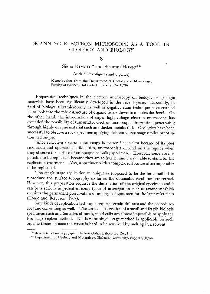
A regular transmission electron microscopic image is formed on a fluorescent
screen or on a photographic plate by the electrons which pass through a specimen.
The transmitted electrons are scattered elastically or inelastically in the specimen
and some of these electrons are obstructed by a small aperture in the focal plane of
the objective lens. The re'sultant absence of such electrons in the image is a prin-
cipal source of image contrast (Fig. 1).
Scanning electron microscope has been developed chiefiy to observe the elec-
trical properties of the semi-conductor divice. However, this instrument has been
found to be a powerfu1 method to observe any solid specimen surface under far
greater magnification than optical methods. Microscopists have been eajoyed its
great depth of focus and the resolution as fine as less than a few hundred angstromes.
The scanning electron microscope can magnify the object in less than a hundred
times up to more than a ten thousand times without a leap of magnification.
The history of the scanning electron microscope can be traced back to1935, to an instrument built by Kn611. ARDENNE (1937) advocated that scanning
microscopy is a promising method to avoid the chromatic error in electron
microscope, ARDENNE (1940), McMuLLAN (19S3) and SMiTH (19S5) constructedpractical models; however, the earlier attempts did not receive particular attention,
because the limit of resolution was not drastically improved over the optical micro-
SCANNING
A
ELECTRON MICROSCOPE AS A
B
TOOL S9
source
illuminatingb
specimen
muai・<(i[!l'r)r71objectivelens
imageplane/
EIectron
Fig. 1
Principals of
mtcroscope
beam
[liiii]XX
XiX
[lff.lll;ll;'JinningIL
AI condenser
1
Zens
image forming in electron
detecbor
speclmen
micoscope (A) and
((l)ii;
I
display
Scanning
scannmg
-lmage
unit
mlcroscope
mlcroscope (B).
scope and the over-all ability of this type of microscope was thought to be quite
inferior to a regular transmission electron microscope.
The behavior of the emitted electrons from the electron bombarded surface has
been precisely studied by EvERHEART, and the Cambridge group since 19S7. Thsoe
studies have led to the remarkable improvement of resolution and image contrast
of the scanning electron microscope and have found a wide field of application,
especially in solid state physics.
Two kinds of electrons are concerned with the image forming in scanning
electron microscope. When an electron beam is directed on a small area, back-・
scattered electrons and secondary electrons are emitted from the bombarded spot.
The backscattered electrons are the original electrons'which are emitted from the
beam source, then reflected on the surface of a sample. The electron bombard-
ment discharges the sample surface, and the electrons fred by the discharge are called
secontinry electrons, The intensity of backscattered and secondary electrons is in-
fluenced by the surface topography and physico--chemical properties of the sample
surface.
Only secondary electrons are detected for image production in regular scanning
microscopy. The resulted secondary electrons are so weak and they are amplified
60 S. KiMoTo and S. HoNJoafter collected by an energy analyzer. The beam spot of electrons which areemitted from a heated filament, is focused on a sample and is swept in a regular
raster with a defiection coil which is synchronized with a modulated light spot on the
tube, and the integration of such light spots forms the enlarged image of the object.
Etvperimental i<ipparatus:
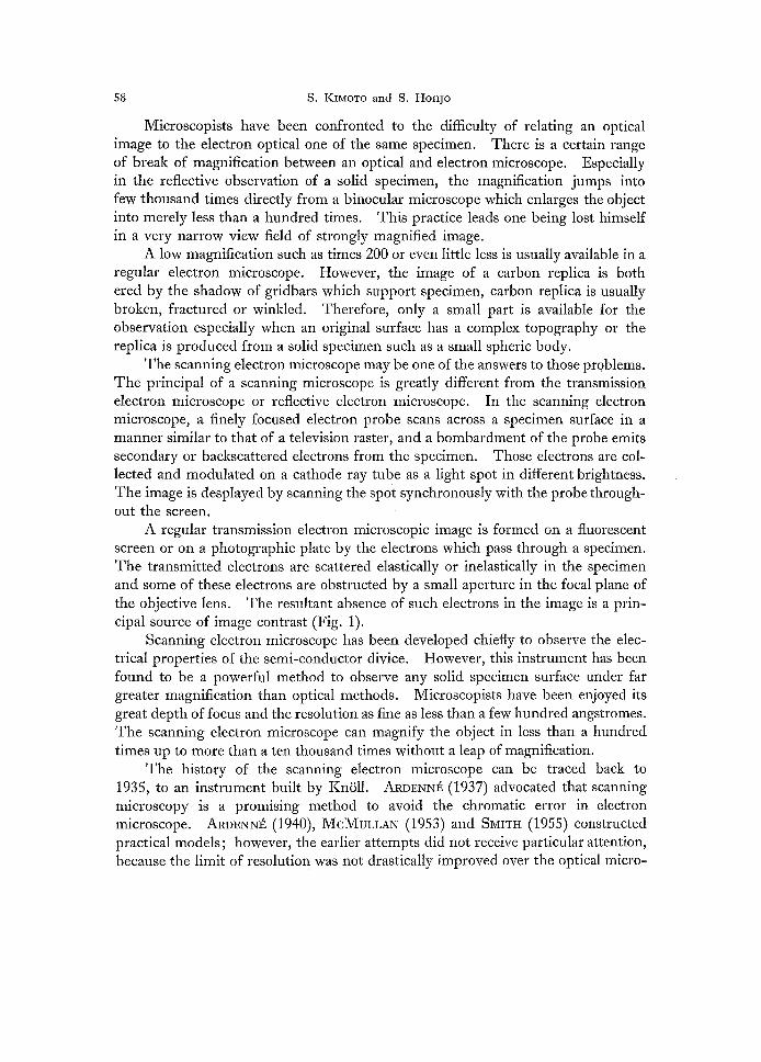
Our experiments are carried out with a JSM scanning electron microscope,
manufactured by Japan Electron Optics Laboratory Co., Ltd., Tokyo.
The whole outfit of instrument consists of three blocks. They are the main
cabinet which includes an electron optical system, specimen chamber, detector
system, etc. Electronic circuits and display unit are facilitated in a control console.
A power supply box is independent.
An electron beam emitted from a heated tungsten filament is finely focused on
a specimen surface by an electron optical system which is provided in the main
column. The electron optical system is composed of a triode electron gun, a single
condenser lens, an objective iens and a astigmator. This system produces finely
focused electron probe with variable energy between 5 to 50 KV. Double scanning
coils are mounted in the objective lens and make the probe sweeping on a specimen.
The magnetic deflection system controls the scanning of the probe in a manner
similar to that of a television raster across the specimen.
In this experiment, a 45 degree inclined specimen stage is used. A horizontal
specimen stage is available to examine a larger specimen as 2S mm in diameter.
A specimen up to 12 mm in diameter, 10 mm in thickness can be fixed onto a speci-
men holder for a inclined specimen stage. In either case, a specimen can be
shifted in two orthogonal directions to examine any desired specific area, Speci--
mens can be exchanged within few minutes through an simple airlock system without
breaking the vacuum of the main part of microscopic column.
The secondary electrons are emitted as a result of excitation by the incident
electron probe and the most of them has low energies which are less than a few
hundredseV. While the backscattered electrons are a portion of the incident elec-
trons which are backscattered from the specimen and their energies are nearly as
large as those of the incident ones. The secondary and the backscattered electrons
are detected by the separate detector systems respectively.
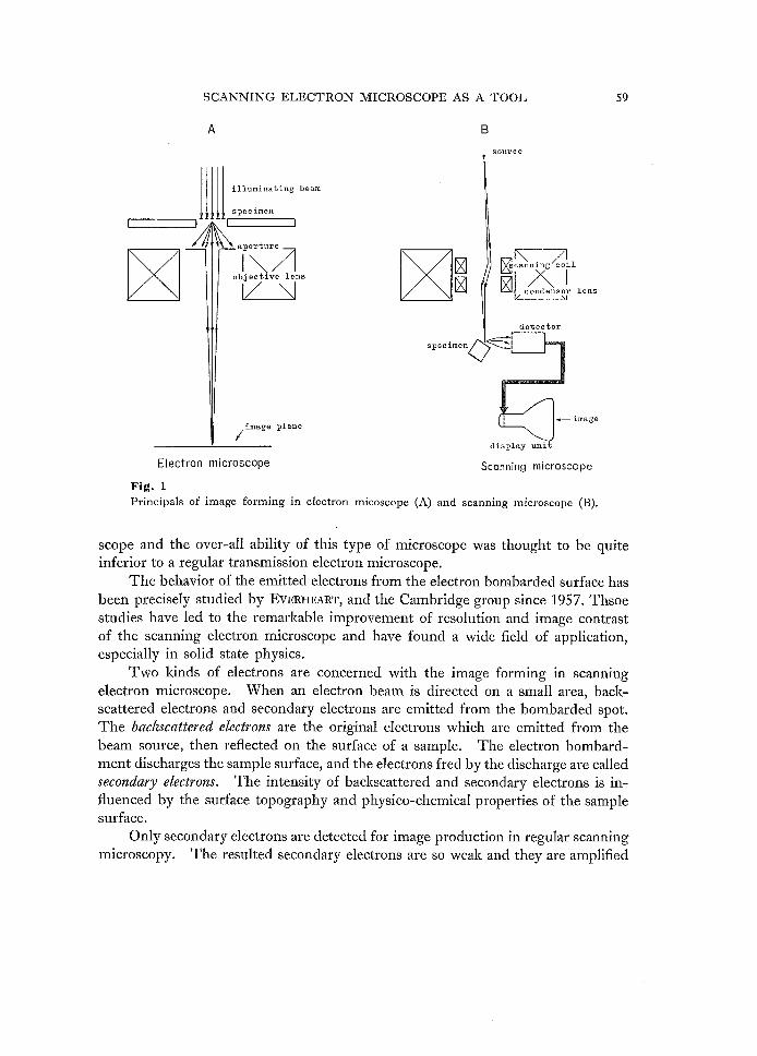
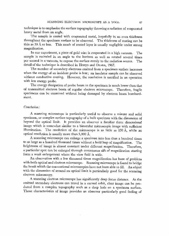
The collecting system for secondary electron consists of electrostatic focusing
electrodes and a positively biased scintillator which is optically coupled to a photo-
multiplier tube through a translucent light pipe. The collected secondary electrons
are accelerated to 10 KV before exciting the scintillator in order to produce a suf-
ficient light intensity. The light energy is amplified through a photomultiplier
tube. The collecting efliciency can be controlled by adjusting the potentials which
are supplied onto a focusing electrodes.
gg'i'
g.diasE
g-mov・mggg2.xeq
B8'8govP
.N.
paN
'
l
1
1
(MA!N CONSOLE)
'
l
l
1
OIL ROTARY
PUMP ×2
OlLDI FFUSI ON
PUMP
VACUUMGAUGE
SAFETY &WARN]NG1NDI CATOR
OPERAT] ONPANEL FOR VACUUM SYSTEM
:
Ltu-lt
--
l
Xx
Xx x
1
l
(DiSPLAY
1
[
[
l
'
i
AND OPERATION
HIGHVOLTAGERECTIFIER
GUNSCILLATOR
H. F,SCi LLATOR
CONOENSER LENS SUPPLY
STIGMATOR SUPPLY
OBJECTIVE LENSSUPPLY
OPERATiON PANELF OR E. O. S,
SYSTEM) ] ll
1
,
-J
t..t--t.tt
SWEEPGENERATORi GRIDBIAS
SUPPLY
[DErECTeR FenSEeONMARYELECTRON)
ACCELE-g.A.TbO.N,
(
SPECI MEN
ll
[oE,T.E,e,T,O,R,
FORTE r
1
PRE-AMPLI- FIER(C)
,,stYf12tl,,
supp y
i
11
ELECTROM pRE-AMPLI FI ER (A)
CONNECTOR BOX
PRE-AMPLI FI ER (B
,
X
X
Xt "
Vi DEO AM PU FI ER &OPERATIONAL AMPLIF!ER{I)
lMAGE SELECTOR-I -o--
2
3
-o4
.ABSORBED
2.
3.
4.
ELECTRON IMAGETOPOGRAPHY[MAGECOMPOSI TI ONlMAGESECONDARYELECTRON tMAGE
1
l] 1
1J
... rr
VIDEO AMPLIFIER &OPERAT[ONAL AMPLiFI ER([)
ii'
・x・
l
---=
za"XH
-
1
if1
[
:
]
F
r
1
l:
E
mot"illZNzopmtrg
ur
osxoZK5xomoovm>m>qoov
Eo-w-ER SUPPLY STABILYZER
9
62 S. KIMoTo and S. HoNJo
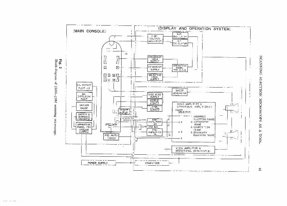
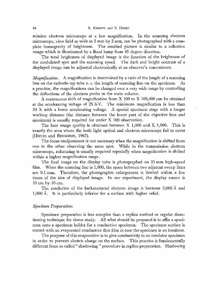
The detector fbr backscattered electrons consists of pair of silicon p-n junc-
tions. This simple detector facilitates an eMcient amplification of the higher energy
electrons (Fig. 2).
The column vacuum is an important factor for the signal gain. The better the
vacuum, the image characteristics are improved. This relation is more clitical in
scanning microscope than regular transmission electron microscope. At least 10-5
torr or better vacuum is required in between the specimen and the secondary elec-
tron collecting electrode. In our experiment, rough vacuum is obtained by mech-
anical rotally pumps and final vacuum, at the better range of 10F5 torr, is furnished
by oil diffusion pumps.
Characteristics of image:
The scanning electron microscopy provides various information from a same
specimen simultaneously, such as the intensity of secondary electrons, backscat-
tered electrons, absorbed electrons, electromotive force, cathodoluminescence and
X-rays, However, we would like to limit our discussion on the secondary and
backscattered electron images, because these two images are the most important for
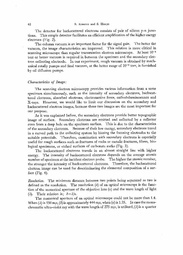
our purpose. As it was explained befbre, the secondary electrons provide better topographic
image of surface. Secondary electrons are emitted and collected by a coliector
even from a deep hole on the specimen surface. This is due to the characteristics
of the secondary electrons. Because of their low energy, secondary electrons travel
in a curved path to the collecting system by biasing the focusing electrodes to the
suitable potentials. Therefore, examination with secondary electrons is especially
usefu1 for rough surfaces such as fractures of rocks or metalic fractures, fibers, bio-
logical specimens, or etched surfaces of carbonate rocks (Fig. 3).
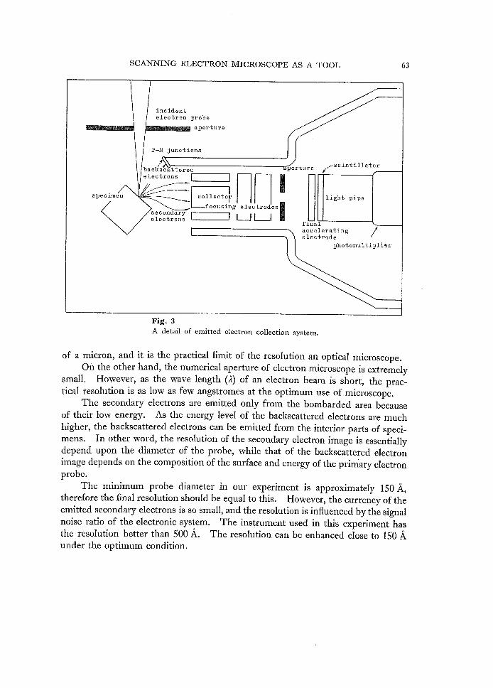
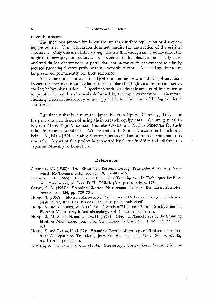
The backscattered electrons travels in an almost straight line with higher
energy. The intensity of backscattered electrons depends on the average atomic
number of specimen at the incident electron probe. The higher the atomic number,
the stronger the intensity of backscattered electrons. Therefbre, the backscattered
electron image can be used for descriminating the elemental composition of a sur・d
face (Fig, 4).
Resointion. The minimum distance between two points being separated as two is
defined as the resolution. The resolution (6) of an optical microscope is the func-
tion of the numerical aperture of the objective lens (a) and the wave length of light
(2). Their relation is; S=21a.
The numerical aperture of an optical microscope could not be more than 1.4.
When (R) is SSO my, (6) is approxirnately 444 mFt, when (a) is 1.25. In case the mono-ny
chromatic ultra-violet ray'with the wave length of 275 mpt, is utilized, (2) is a quarter
SCANNING ELEC'I'RON MICROSCOPE AS A TOOL 63
incidentelectron probe
aperture
P-N ]'unetions
speclmen
/batckscattered
electrons Mv
secondaryelectrons
O,ecO-desl
uLl g
perture
collector 1focusing
/scintillator
light pipe
finalacceleratinff oelectrode
/
photomultiplier
Fig. 3
A detail of emitted electron collection system.
of a micron, and it is the practical limit of the resolution an optical microscope.
On the other hand, the numerical aperture of electron microscope is extremely
small. However, as the wave length (2) of an electron beam is short, the prac-
tical resolution is as low as few angstromes at the optimum use of microscope.
The electrons are emitted only from the bombarded area because secondary
of their low energy. As the energy level of the backscattered electrons are much
higher, the backscattered electrons can be emitted from the interior parts of speci-
the resolution of the secondary electron image is essentiallymens. Inotherword,depend upon the diameter of the probe, while that of the backscattered electronimage depends on the composition of the surface and energy of the prim'ary electron
probe.
The minimum probe diameter in our experiment is approximately 150A,therefore the final resolution should be equal to this. However, the currency of the
emitted secondary electrons is so small, and the resolution is influenced by the signal
noise ratio of the electronic system, The instrument used in this experiment has
the resolution better than 500 A. The resolution can be enhanced ciose to 150 A
under the optimum condition,
64
pA
l4
t"s
g
6 12g8
brd. IO:kH
g¢
v81:
:6v
gx
S4gcexm
l2
S. KiMoTo and S. HoNJO
] lN '
xi
Nx
:2I
I・l/
xxN I
I
NIi'
N :
×N II
IIxl [
x L
E
N I
NN :
N l
NN
O.29
O.27
O.25
O.23
O.21
O.19
O,17
AgtntsH
hpvG::e
g£:
G
E
l
l
10 20 30 40 50 60 70 80 90 Atornic Number
Fig. 4The relation between intensity of bacl{scattered current and the atomic number of the
bombarded specimen.
Dqfinition. The definition of microscopic image is depend on the astigmatism of
the probe spot and chromatic error of the probe beam.
The astigmatism can be minimized with the electronically controlled stigmator.
Since the supply of high voltage to the electron gun is highly stablized by the stabliz-
ing circuit, chromatic error is almost negligible.
The number of scanning lines on the final dispay is also an important factor
for the image demarcation, In our experimental instrument, 1,eOO scanning lines
are available for the maximum performance.
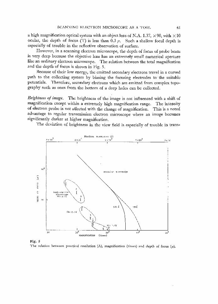
Dopth qf'focus. In an optical microscope, the depth of focus is in reverse relation
to the numerical aperture of the objective lens (a) and the total magnification.
Therefore, the depth of focus (T) is shallower at a higher magnification. When a
total magnification is (M), and the index of the material surrounding the object is
n; T(pt)i=iO.24nfaM.
For instance, a Cargille's oil (n=:1.515) immersed specimen is observed with
SCANNING ELECrl"RON MICROSCOPE AS A TOOL 65
a high magnification optical system with an object lens of N.A. 1.37, × 90, with × 10
ocular, the depth of focus (T) is less than O.3 pt. Such ashallow focul depth is
especially of trouble in the refiective observation of surface.
However, in a scanning electron microscope, the depth of focus of probe beam
js very deep because the objective lens has an extremely small numerical aperture
Iike an ordinary electron microscope. The relation between the total magnification
and the depth of focus is shown in Fig. 5.
Because of their low energy, the emitted secondary electrons travel in a curved
path to the collecting system by biasing the focusing electrodes to the suitable
potentials. Therefbre, secondary electrons which are emitted from complex topo-
graphy such as ones from the bottom of a deep holes can be collected.
'Brightness of image. The brightness of the image is not infiuenced with a shift of
magnification except within a extremely high magnification range. The intensity
of electron probe is not affected with the change of magnification. This is a noted
advantage to regular transmission electron microscope where an image becomes
significantly darker at higher magnification.
The deviation of brightness in the view field is especially of trouble in transil=
2x10⁵
PRATICAL RESeLUSION 42XIO 2x
(x}
3!o 2xlo22x 10
lo2
3
9BA
g
:k ioA
seannlng mieresco'pe
xl "x [s txtl 'Sx
tt Xs SN N2N LN sNii mghi:I:g::;2Vsx l Xx tsx NA: o.2S kX 3X XN. Xx I 1/ sl si y-.- .4--. sooX t;' I "hs.s NA:o.7o X x sX I s5X ss NN ssx...{LR.)1'
ltt---L-x `i3.xx ""IB-.N.et !'25
xxxxx e'X 15eA
x N N x x x x
x
xN
10・ io2 io MAGNIFICATION {times)
Fig. 5
The relation between practical resolution (A),
3
magnification
IO4
(times) and depth of
lo5
focus (p)・
66 S. KiMoTo and S. HoNJomission electron microscope at a low magnification. In the scanning electron
microscope, view field as wide as 2 mm by 2 mm, can be photographed with a comhi
plete homogenity of brightness. The resulted picture is similar to a reflective
image which is illuminated by a flood lump from 45 degree direction.
The total brightness of displayed image is the function of the brightness of
the modulated spot and the scanning speed. The dark and bright contrast of a
displayed image can be adjusted electronically at an observer's convenience.
Magnipcation, A magnification is determined by a ratio of the length of a scanning
line on the cathode--ray tube w. s. the length of scanning line on the specimen. As
a practice, the magnifications can be changed over a very wide range by controlling
the deflections of the electron probe in the main column.
A contenuous shift of magnification from X 100 to X 100,OOO can be obtained
at the accelerating voltage of 25 KV. The minimum magnification is less than
30 X with a lower accelerating voltage. A special specimen stage with a longer
working distance (the distance between the lower part of the objective lens and
specimen) is usually required for under X 100 observation.
The best image quality is obtained between X i,OOO and X 5,OOO. This is
exactly the area where the both light optical and electron microscope fail to cover
(HoNJo and BERGGREN, 1967). The fbcus readjustment is not necessary when the magnification is shifted from
one to the other observing the same spot. While in the transmission electron
microscope, refocusing is usually required especially when magnification is shifted
within a higher magnification range.
The final image on the display tube is photographed on 3S mm high-speed
film. When the scanning line is 1,OOO, the space between two adjacent sweep lines
are O.1 mm. Therefbre, the photographic enlargement is limited within a few
times of the size of displayed image, In our experiment, the display screen is
10 cm by 10 cm. The resolution of the backscattered electron image is between S,OOOA and
1,OOO A. It is particularly inferior for a surface with higher relief.
SPecimen Preparation:
Specimen preparation is less complex than a replica method or regular disec-
tioning technique for tissue study. All what should be prepared is to afix a speci-・
men onto a specimen holder for a conductive specimen. The specimen surface is
coated with an evaporated conductive thin film in case the specimen is an insulator.
The purpose of this evaporation is to give conductivity to an insulator specimen
in order to prevent electric charge on the surface. This practice is fundamentally
different from so called " shadowing " procedure in replica preparation, Shadowing
SCANNING ELECTRON MICROSCOPE AS A 'IrOOL 67technique is to emphasize the surface topography throwing a radiation of evaporated
heavy metal from an angle,
The sample is coated with evaporated metal, hopefu11y in an even thickness
throughout. the specimen surface to be observed, The thickness of coating can be
thin as 30 A or less. This much of coated layer is usually negligible under strong
magnification.
In our experiment, a piece of gold wire is evaporated in a high vacuum. The
sample is swiveled in an angle to the horizon as well as rotated several times
per second in a vacuum, to expose the surface evenly to the radiation source. The
detail of the technique is described in HoNJo and OKADA, 1967.
The number of secondary electrons emitted from a specimen surface increases
when the energy of an incident probe is low; an insulator sample can be observed
without conductive coating. However, the resolution is sacrified in an operation
with low energy probe.
The energy dissipation of probe beam in the specimen is much lower than that
of transmitted electron beam of regular electron microscope, Therefore, fragile
specimens can be examined without being damaged by electron beam bombard-ti
ment.
Concinsion:
A scanning microscope is particularly usefu1 to observe a minute and solid
specimen, or complex surface topography of a bulk specimen with the dimension of
beyond the optical limit. It provides an observer a familiar three dimensional
image which is somewhat similar to a binocular microscopic image with sufficient
illumination. The resolution of the microscope is as little as ISOA, while an
optical resolution is usually more than S,OOO A.
A scanning microscope can enlarge a specimen into less than a hundred times
to as large as a hundred thousand times without a bold leap of magnification. The
brightness of image is almost constant under diflerent magnification. Therefore,
a particular spot can be enlarged through contenuous sift of magnification starting
form a weak enlargement where the view field is wide,
An observation with a few thousand times magnification has been of problem
with both optical and electron microscope. Scanning microscope is found to bridge
the break which the conventional microscopies have not been ,able to fi11. An object
with the dimension of around an optical limit is particularly good for the scanning
electron microscopy.
A scanning electron microscope has significantly deep focus distance. As the
emitted secondary electrons can travel in a curved orbit, clear image can be pro-
duced from a complex topography such as a deep hole on a specimen surface.
Those characteristics of image provides an observer particularly good feeiing of
68 S. KiMoTo and S. HoNJothree dimensions.
The specimen preparation is less tedium than surface replication or disection-
ing procedure. The preparation does not require the destruction of the original
specimen. Only thin metal film coating, which is thin enough and does not affect the
original topography, is required. A specimen to be observed is usually keep
unaltred during observation; a particular spot on the surface is exposed to a finely
focused sweeping electron probe within a very short time. A coated specimen can
be preserved permanently for later reference.
A specimen to be observed is subjected under high vacuum during observation.
In case the specimen is an insulator, it is also placed in high vacuum for conductive
coating before observation. A specimen with considerable amount of free water or
evaporative material is obviously deformed by the rapid evaporation. Therefore,
scanning electron microscopy is not applicable for the most of biological tissue
'speclmens.
Our sincere thanks due to the Japan Electron Optical Company, Tokyo, for
the generous permission of using their research equipments. We are gratefu1 to
Kiyoshi MAsE, Yuji NAKAJiMA, Hisatake OKADA and Nachio MiNouRA for theirvaluable technical assistance. We are gratefu1 to Sumio KuMANo fbr his editofial
help. A JEOL-JSM scanning electron microscope has been used throughout this
research. A part of this project is supported by Grant-in-Aid Ah-091008 from the
Japanese Ministry of Education.
References
ARDENNE, M. (1938): Das Elektronen Rastermikroskop, Praktische Aufifhrung, Zeit-
schrift fUr Technische Physik, vol. 19, pp. 407-416.
BRADLEy, D. E. (1965): Replica and Shadowing Techniques. In Techniques for Elec-
tron Microscopy, ed. Kay, D. H., Philadelphia, particularly p. 137.
CREws, C.A. (1966): Scanning Electron Microscope: Is High Resolution Possible?,
Science, vol, 154, pp. 729-738.
HoNJo, S. (1967): Electron Microscopic Techniques in Carbonate Geology and Nanno-
fdssil Study, Rep. Res. Kansas Geol. Sur. (to be published).
HoNJo, S. and BERGGREN, W. A. (1967): A Study of Pianktonic Forminifera by Scanning
Electron Microscope, Micropaleonology, vol. 13 (to be published).
HoNJo, S., MiNouRA, N, and OKADA, H. (1967): Study of Nannofbssils by the Scanning
Electron Microscope, Jour. Fac. Sci., Hokkaido Univ. Ser. 4, vol. 13, pp. 427-
431.HoNJo, S. and OKADA, H. (1967): Scanning Electron Microscopy of Planktonic Formini-
fera; A Preparation Technique, Jour. Fac. Sci., Hokkaido Univ., Ser. 4, vol. 15,
no. 1 (to be published).
KiMoTo, S. and HAsHiMoTo, H. (1964): Stereoscopic Observation in Scanning Micro-
P

SCANNING ELECTRON MICROSCOPE AS A TOOL 69 scopy Using Multiple Detectors, Read to Symp. Electrothemics and Metall., Electro-
chem. Soc,, Washington, D, C., John Wiley and Sons, N, Y.
KiMoTo S. HAsHmoTo, H. and SATo, M. (1966): On a Scanning Type Electron Micro-
scope, Sixth International Congress fbr Electron Microscopy, Kyoto, Japan, vol. 1,
pp. 197-198, Maruzen Co., Tokyo.KN6LL, M. (1935): Aufladepotent{al und Schundiremission electronenbestrahlter K6r--
per, Zeitschrift fur Technische Physik, vol. 16, pp. 467-47S.
McMuLLAN, D. (1953): An Improved Scanning Electron IVIicroscope for Opaque Speci-
mens, Proc. Inst. Elct. Engneer. vol. 100, pp. 245-259.
OATLEy, C. W, (l958): The Scanning Electron Microscope, Allew Scientist, vol. 5, p. 155.
(Manuscript recieved July 16, 1967)

1董AN夏)鴛XP影A翼AT玲LA
ExplaRation of Plate ll
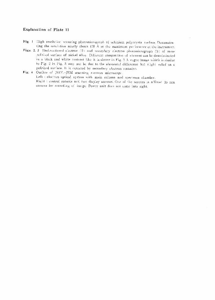
Fig. 1 High reso}ution scanning photomicrograph of selenium polycrystal surface, Demonstra-
ting the }"esolution near}y clears 150 A at the maximum performnce of the instrument,
Figs, 2, 3 Backscattered electron (2) and seconclary e]ectron photomicrograph (3> of same
polished surface of nickel alloy. Different composition ol' element can be descriminated
in a black-and-white contrast iike it is shown in Fig. 2 A vague image which is similar
to Fig. 2 in Fig. 3 may not be due to the elementai difference but slight relief on a
polished surfaee, It is cletected bv secondarxr eleetron ernission,
Fig. 4 Outline oi' .IEOL-JSM scanning electron microscope. Lelt : electron optical system x・vith main column and specimen chamber. Right '. control console and two display screens. One of the $creens is aft'ixed 35 mm
camera t'or recorcling of image. Power unit cloes, not conie into sight.
K至M(.)iC)anCl H(.)\」O SしanlMng eieCtroll InlcrosCol)e
P茎ate 11
晶
靴
鰍・
藩
4

PLATE 12 AND EXPLANATIO

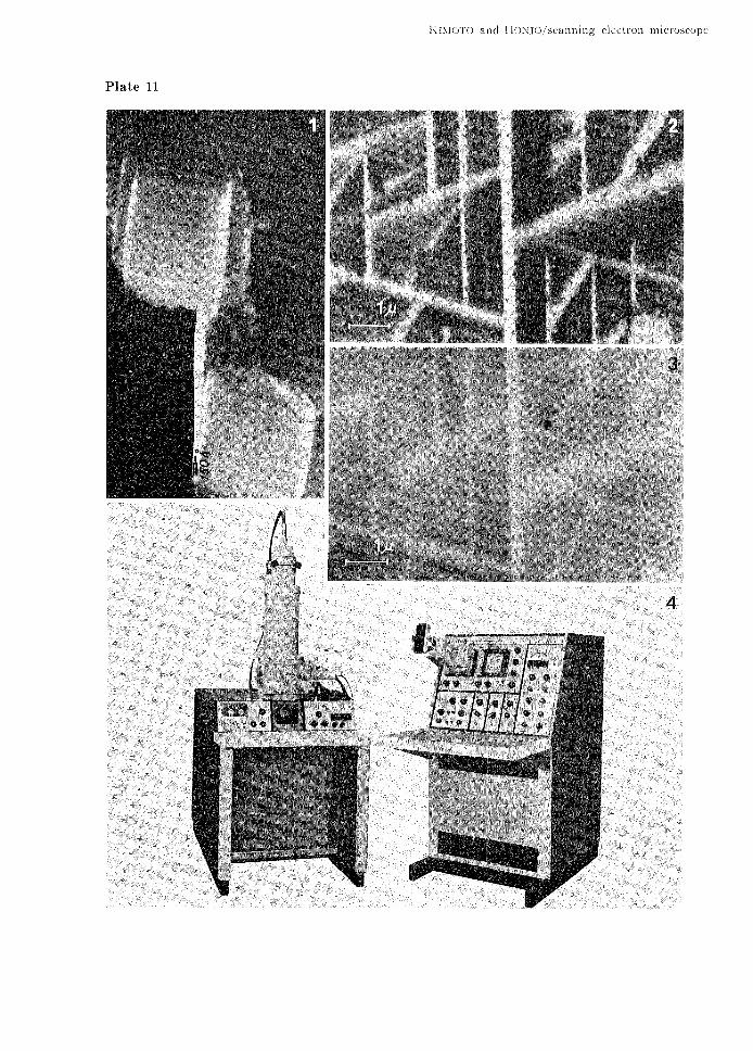
Explanation of I'late l2
Scanning photomicrograph oi' Hantfeenina alabamaensis CusHMAN
IJ'ig, 1 A time consuming sketch of a naicroi'ossils can be replaced by the low magnification
scanning micrograph,Fig. 2, 3 rl"he magniiication between X 1,OOO to 5,OOO times is par-ticularly usul'ul, The
depth of focus is still deep enough at X 5, OOO for this much of relietT.
Fig, 4 Ciose up photo of a perforation in Fig, 3 Secondary electron image prox,ides better
itnage of comp}ex topography even from the bottoni of a hole.
KIMo'ro and HONJO,'ScEinning electron mlcroscope
Plate I2
geut .vea imSSkiS
w-
itijbe・
'tigeSk-
・@・ ,tt- ,ltt 'thew

13A醤豆)遍XP監ANA.顎◎NA

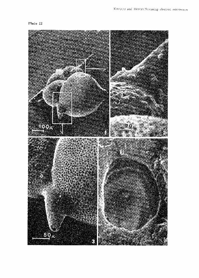
EXplanatioil of Plate
Recent pollen g. rains ancl
i3
the close up. Species unknoivn,
Ik]LdoTo and I'IoNJo /Scanning electr'on mlcroscope
P}ate 13
ge
x,r
k' ¥.
va
pa.
ges.vet
dig
mpigtw
tiLtwin.
・wa
as
as-nt
-・
as
'k'-.
/:."・
ttbl
-eets,
.genvst."-,
ec
esS' A・
ne
g
zaxwwew'gept
imeq
'scyas ...t,tuwtvt ..t ex.-k$ins ...-im-..t..

PLATE 14 AND EXPLANA7貰ON

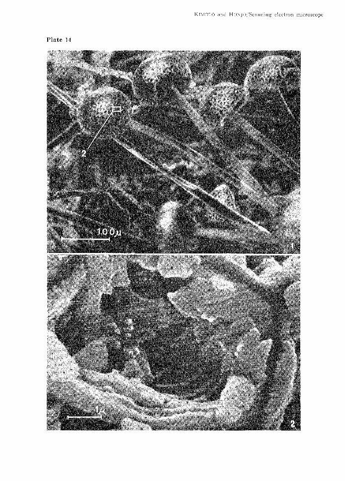
Explanation ef Plate 14
A cluste}' ot'
signiticant]y
dehvdration.
inoth. ,As
deformecl,
Notice the
the specimen'v. i, a ``calix
magnificent
Nvas subjected in a high
shin'' is turned inside
clepth of i'ocus,
vacuunl, lt "Tas
out. Stems are
dehydrated
constricted
and b},
n1且CrOSCOpeelectro罰HつNJご)/Scannh19alld1く夏N’1(.)「rc)
14P韮ate
碑簸
、誌膨
霧
嚢鱈 鴛。ド内売β
鍔譜パ
彫
籔、、凡掃ご
夢繧
伽
轟、勲
蒸熱
繋
・・、、・曽..璃Pフ、ご・瀟欝離
欝響
予嚇欝欝く ’…内 M姦...讐驚
愈縦鮎.鴫騰議
緯職
譲

15AN蔓)EXP瓢A}マA710P亙。A

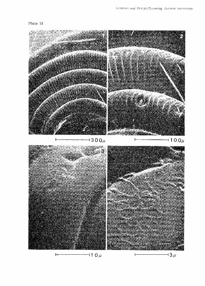
Explanation of Plate 15
Proboscis of a moth of unidentii'ied species,
cenes ancl pegs sunk in shailow depressions
li]{ely to be ehemoreceptors, Peculiar patters
oi
Oll
on
note is the presence of two types ol' sensilla,
the surface (Upper left, right.//, They are
a segment surface (lo"'e}' Ieft, rgght.s,
inlC「OSCOpeelectrOn1-lr)Njo/Scamlin91く二INI()rギ() alld
15P藍ate
ぜ難壁4・
蕊繍 「黛シ
、藪淋
郵醗響、伍、
》.餓欝欝馨
説
撫
磁漉編
添蕨
ウへ
・㌦臨へ
ぐ.くへ・ ド禽..飲粛
なぴ
@
@織隠
ゴ内ご擁鵠鍬
ひ勢
v∴ぐ凪凡.の∵
い博踊躍撚齢、・
こ内閣 ㌔
と梅簗/シ 讃
灘瀦灘
0O1030
無難譲
縫・
磁騨
簿慧
、門下湘轍へ
念胤^ 匹
㌦/
内て匁ぐ
㌧「
執競難
慰、然懇懇
,驚難
トー一一一一一一→30μ1

PLA7E 16 A潜D EXPLANA翌玲N

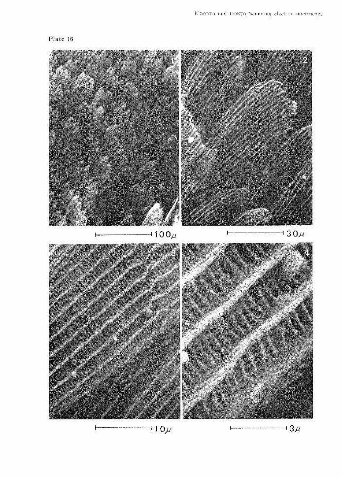
Expl往nat壼OR of P垂ate 16
Bu重亡erfly scales(.F量9,1,2)and thel…・texture(.F量93,・1)
K韮NI(.)「韮、(.) Zl 1、⊂… {一1(:)NJO,Seanllillg eiectroll lユユ1croscope
Pla重e 16
薮. 躍
籔トー一100μ ト 一一30μ
ト 州10μ トー一一一一一一→3み


![Loeng 1 - utkodu.ut.ee/~jaakk/oppetoo/LOFY_02_002/LOFY_02_002k_3.doc · Web view[In] the JSM-6400 scanning electron microscope ... the energy of electrons in the electron beam can](https://img.pdfslide.tips/doc/110x75/60628b12b4cca93c0445bcbc/loeng-1-jaakkoppetoolofy02002lofy02002k3doc-web-view-in-the-jsm-6400.jpg)