Embed Size (px)
Citation preview
Subsea Deployment Systems Ltd.
The SDS Skip
Subsea Deployment Systems Ltd.
2
SUBSEA SKIP•An alternative to enhance the recovery of structures, spool pieces, mattresses etc. during decommissioning work
•Can be used to transport complex structures or spool pieces to field for installation by another vessel
•Reduces working and transit time for more costly vessel
•Operations have decreased weather dependency
•Safer than lifting to deck
•Schedule flexibility
Subsea Deployment Systems Ltd.
3
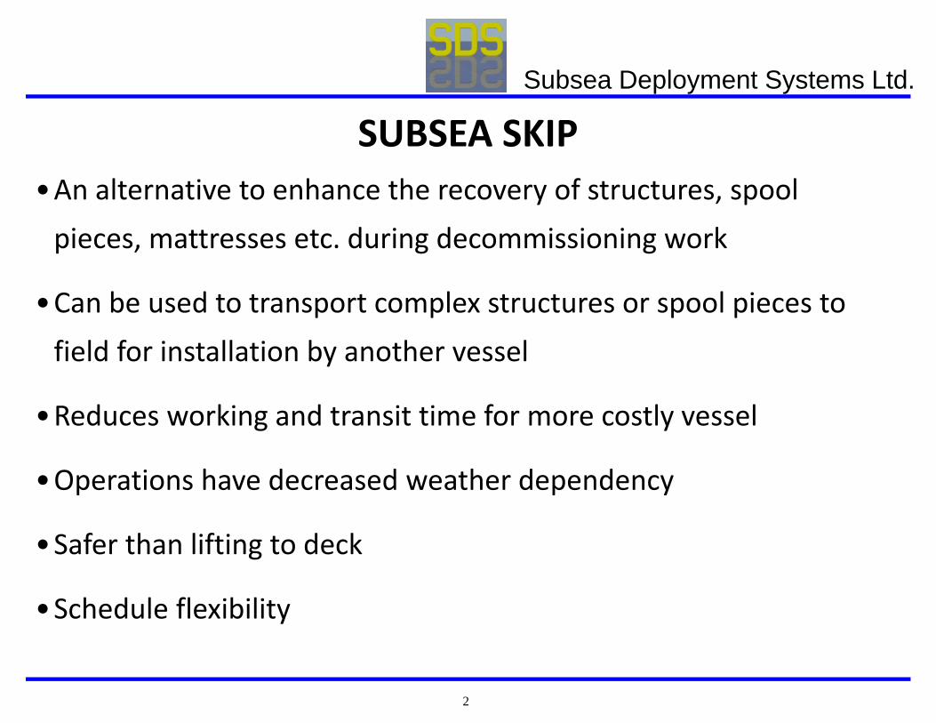
The SKIP consists of UPPER SEALED TUBULARS designed to required water depth (typ. 150m). The amount of buoyancy is sufficient to render the SKIP slightly positively buoyant when without payload and the lower tubular fully flooded
SKIP
Subsea Deployment Systems Ltd.
4
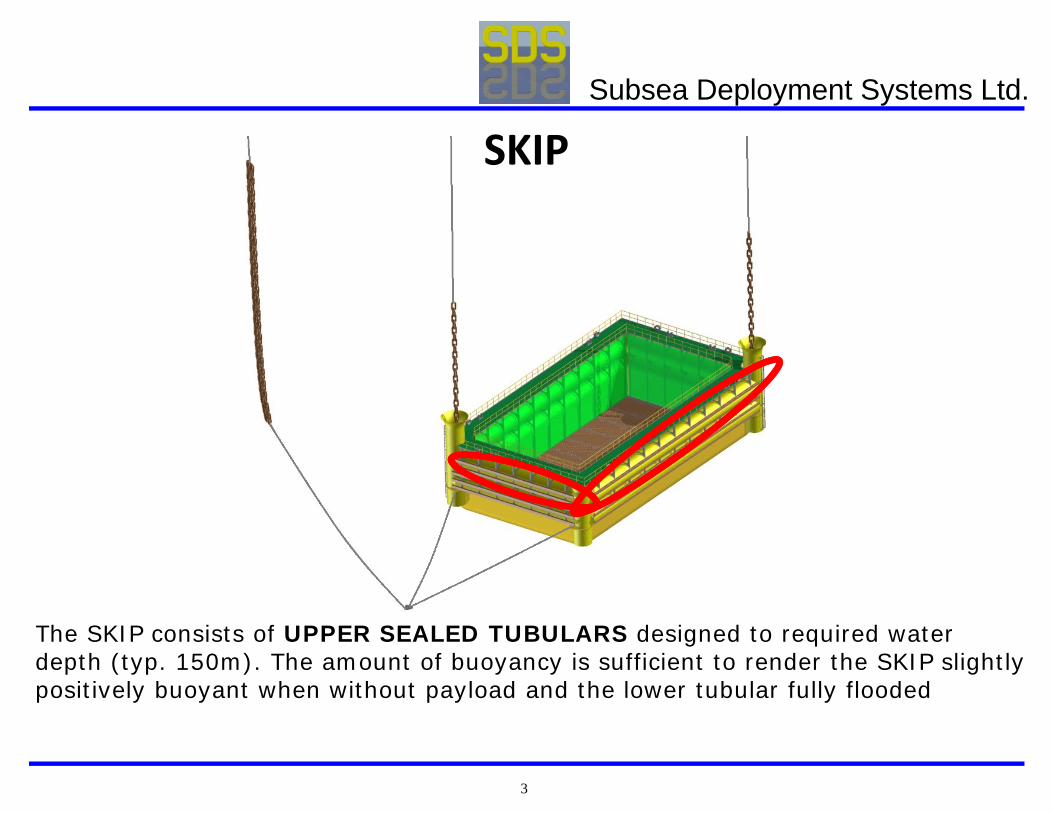
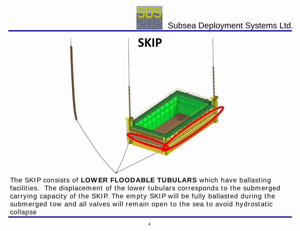
The SKIP consists of LOWER FLOODABLE TUBULARS which have ballasting facilities. The displacement of the lower tubulars corresponds to the submerged carrying capacity of the SKIP. The empty SKIP will be fully ballasted during the submerged tow and all valves will remain open to the sea to avoid hydrostatic collapse
SKIP
Subsea Deployment Systems Ltd.
5
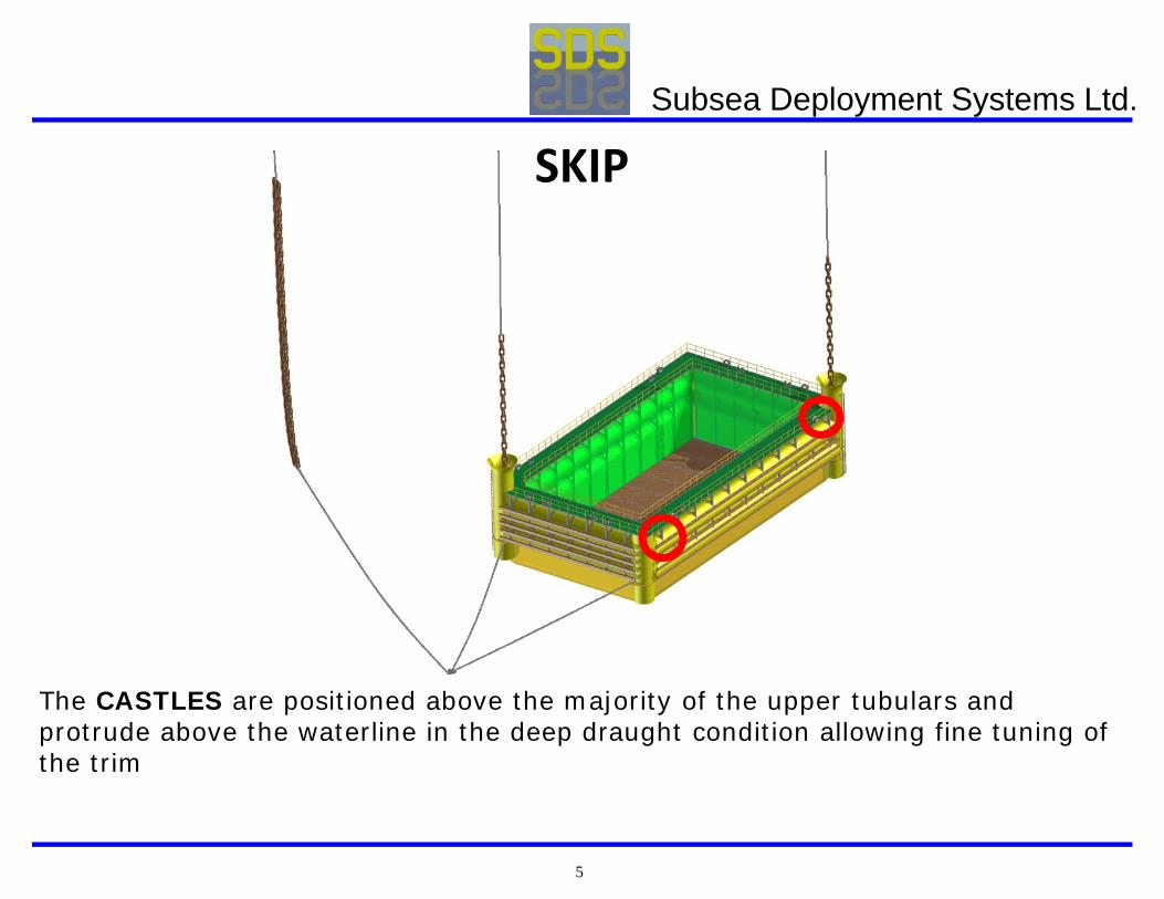
The CASTLES are positioned above the majority of the upper tubulars and protrude above the waterline in the deep draught condition allowing fine tuning of the trim
SKIP
Subsea Deployment Systems Ltd.
6
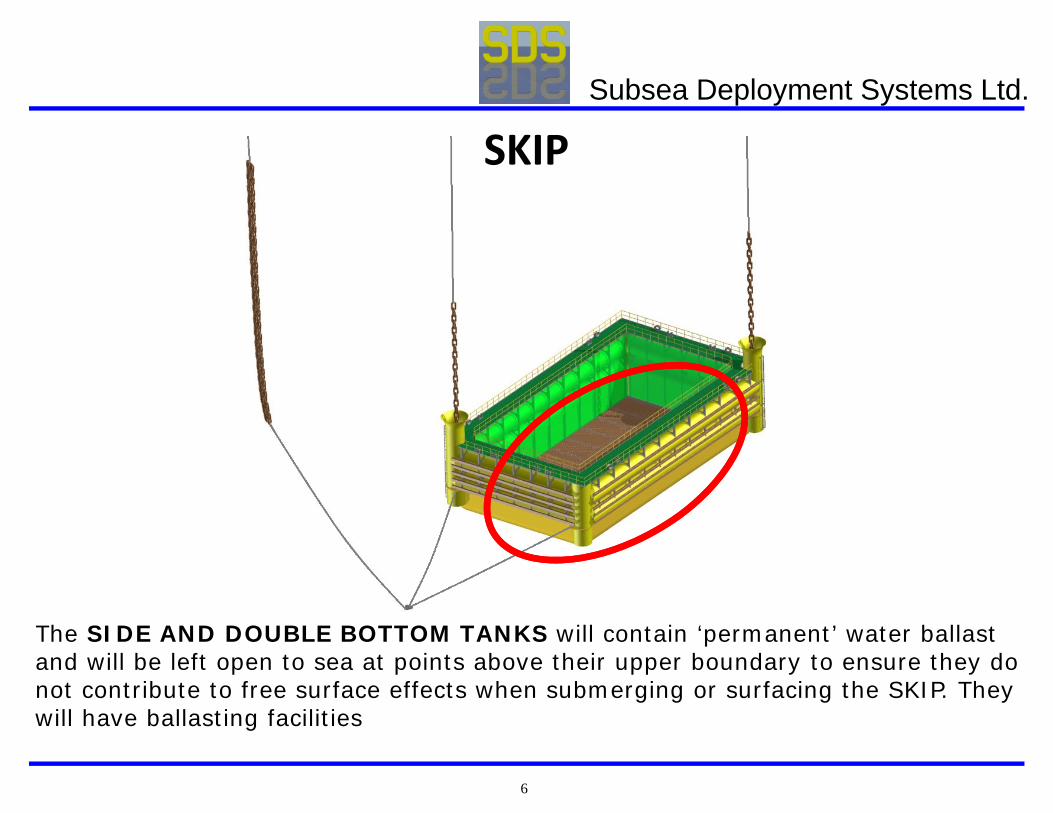
The SIDE AND DOUBLE BOTTOM TANKS will contain ‘permanent’ water ballast and will be left open to sea at points above their upper boundary to ensure they do not contribute to free surface effects when submerging or surfacing the SKIP. They will have ballasting facilities
SKIP
Subsea Deployment Systems Ltd.
7
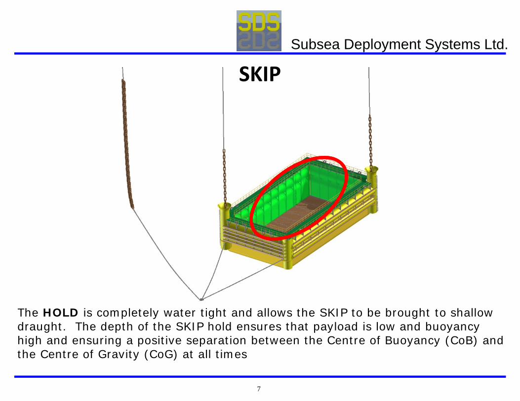
The HOLD is completely water tight and allows the SKIP to be brought to shallow draught. The depth of the SKIP hold ensures that payload is low and buoyancy high and ensuring a positive separation between the Centre of Buoyancy (CoB) and the Centre of Gravity (CoG) at all times
SKIP
Subsea Deployment Systems Ltd.
8
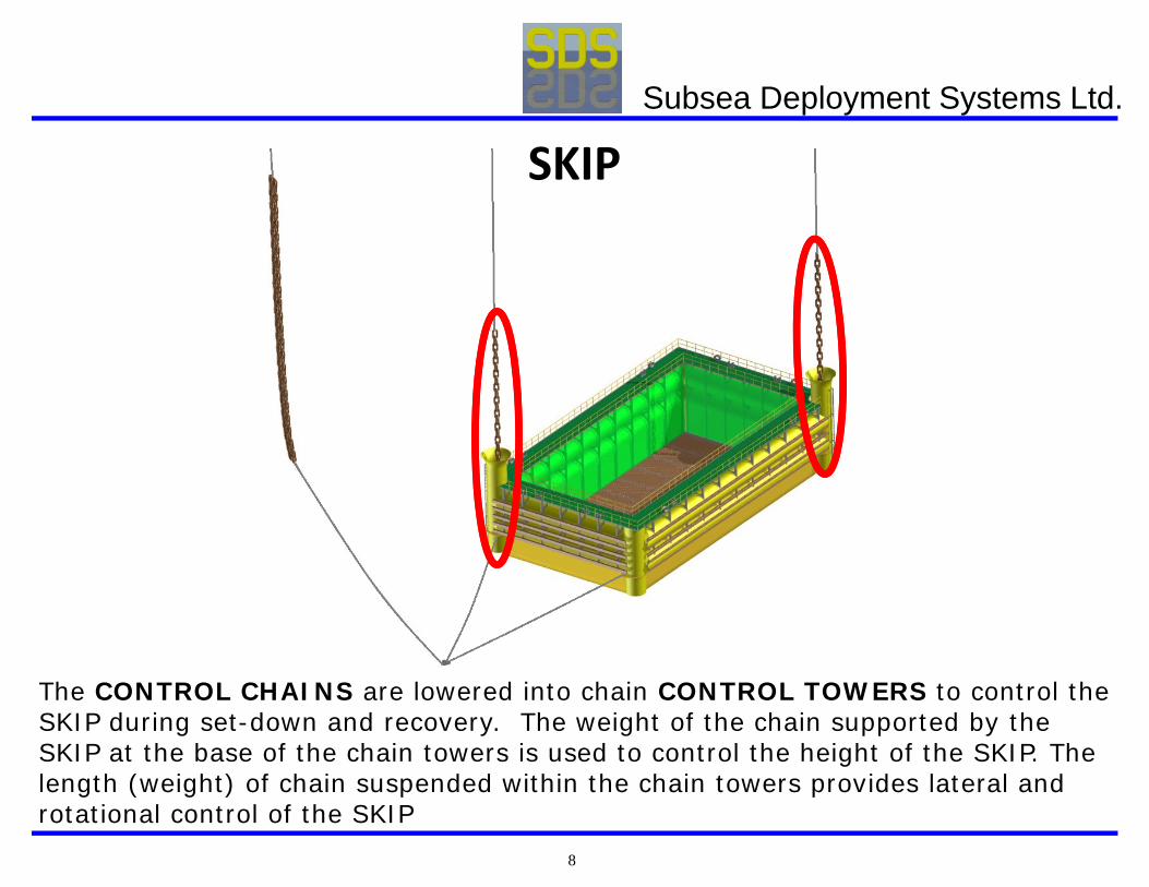
The CONTROL CHAINS are lowered into chain CONTROL TOWERS to control the SKIP during set-down and recovery. The weight of the chain supported by the SKIP at the base of the chain towers is used to control the height of the SKIP. The length (weight) of chain suspended within the chain towers provides lateral and rotational control of the SKIP
SKIP
Subsea Deployment Systems Ltd.
9
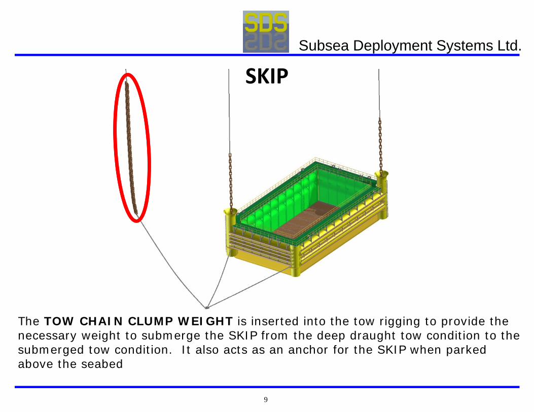
The TOW CHAIN CLUMP WEIGHT is inserted into the tow rigging to provide the necessary weight to submerge the SKIP from the deep draught tow condition to the submerged tow condition. It also acts as an anchor for the SKIP when parked above the seabed
SKIP
Subsea Deployment Systems Ltd.
10
HOW SDV WORKS
Subsea Deployment Systems Ltd.
11
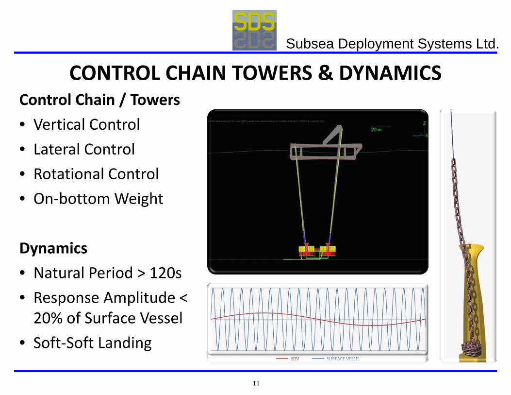
CONTROL CHAIN TOWERS & DYNAMICSControl Chain / Towers• Vertical Control• Lateral Control• Rotational Control• On‐bottom Weight
Dynamics• Natural Period > 120s• Response Amplitude < 20% of Surface Vessel
• Soft‐Soft Landing
Subsea Deployment Systems Ltd.
12
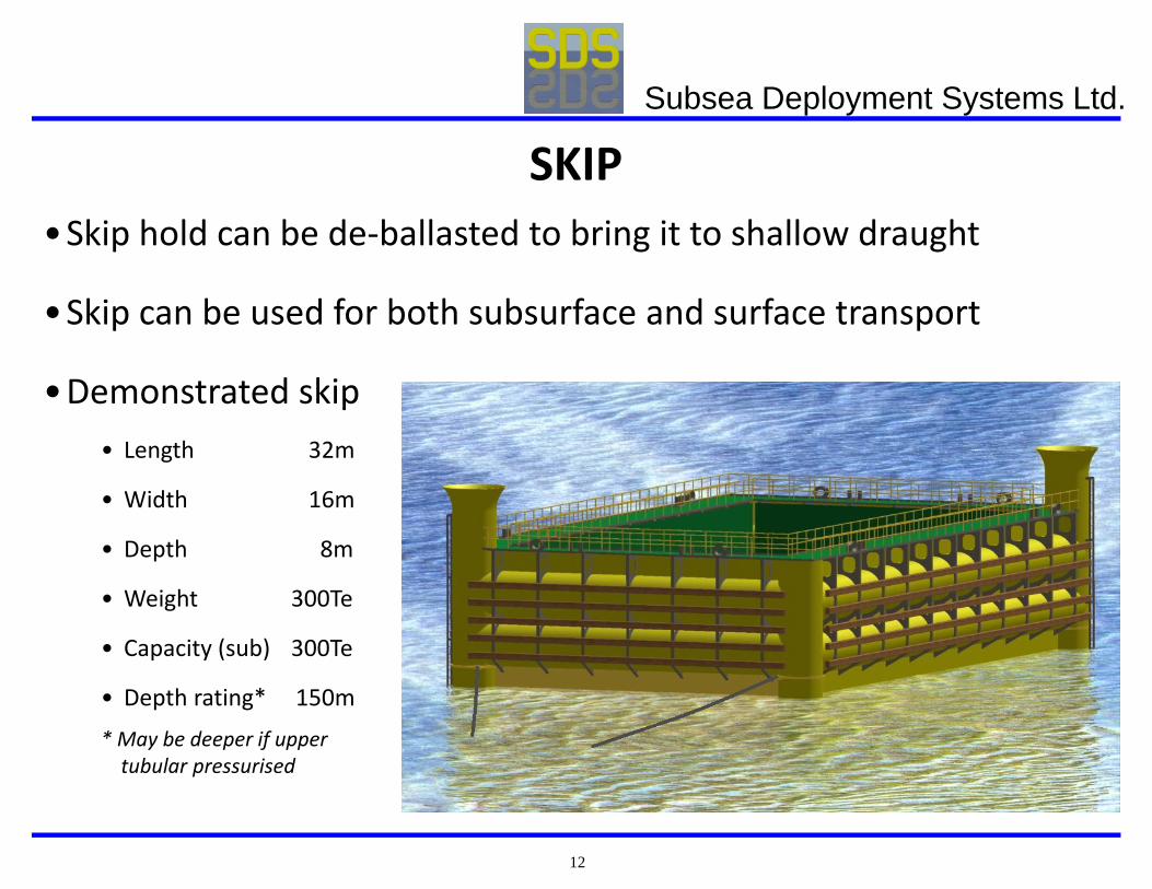
SKIP•Skip hold can be de‐ballasted to bring it to shallow draught
•Skip can be used for both subsurface and surface transport
•Demonstrated skip• Length 32m
• Width 16m
• Depth 8m
• Weight 300Te
• Capacity (sub) 300Te
• Depth rating* 150m
* May be deeper if uppertubular pressurised
Subsea Deployment Systems Ltd.
13
SKIP BASICS•Upper tubulars are fully sealed and buoyant and designed for the maximum water depth
•Lower tubular compartments are designed with a ballasting facility
•Side and double bottom compartments are fully flooded and open to the sea
•Skip fitted with remotely operated system (power and control pods) to control the de‐ballasting function of the hold
•The hold is fitted with centrifugal pumps powered by the pressurised air in the lower tubular compartments
Subsea Deployment Systems Ltd.
14
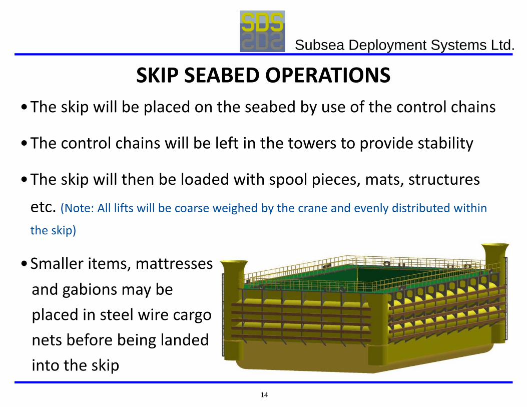
SKIP SEABED OPERATIONS•The skip will be placed on the seabed by use of the control chains
•The control chains will be left in the towers to provide stability
•The skip will then be loaded with spool pieces, mats, structures etc. (Note: All lifts will be coarse weighed by the crane and evenly distributed within the skip)
•Smaller items, mattressesand gabions may beplaced in steel wire cargonets before being landedinto the skip
Subsea Deployment Systems Ltd.
15
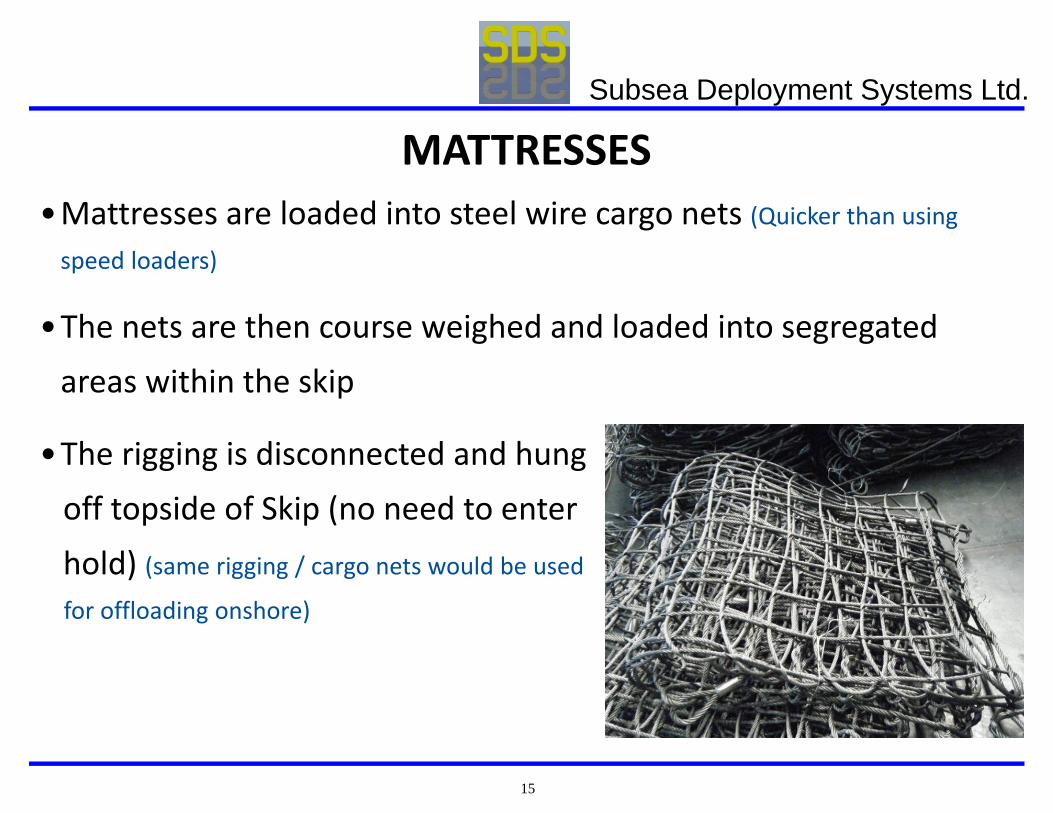
MATTRESSES•Mattresses are loaded into steel wire cargo nets (Quicker than using speed loaders)
•The nets are then course weighed and loaded into segregated areas within the skip
•The rigging is disconnected and hungoff topside of Skip (no need to enterhold) (same rigging / cargo nets would be used
for offloading onshore)
Subsea Deployment Systems Ltd.
16
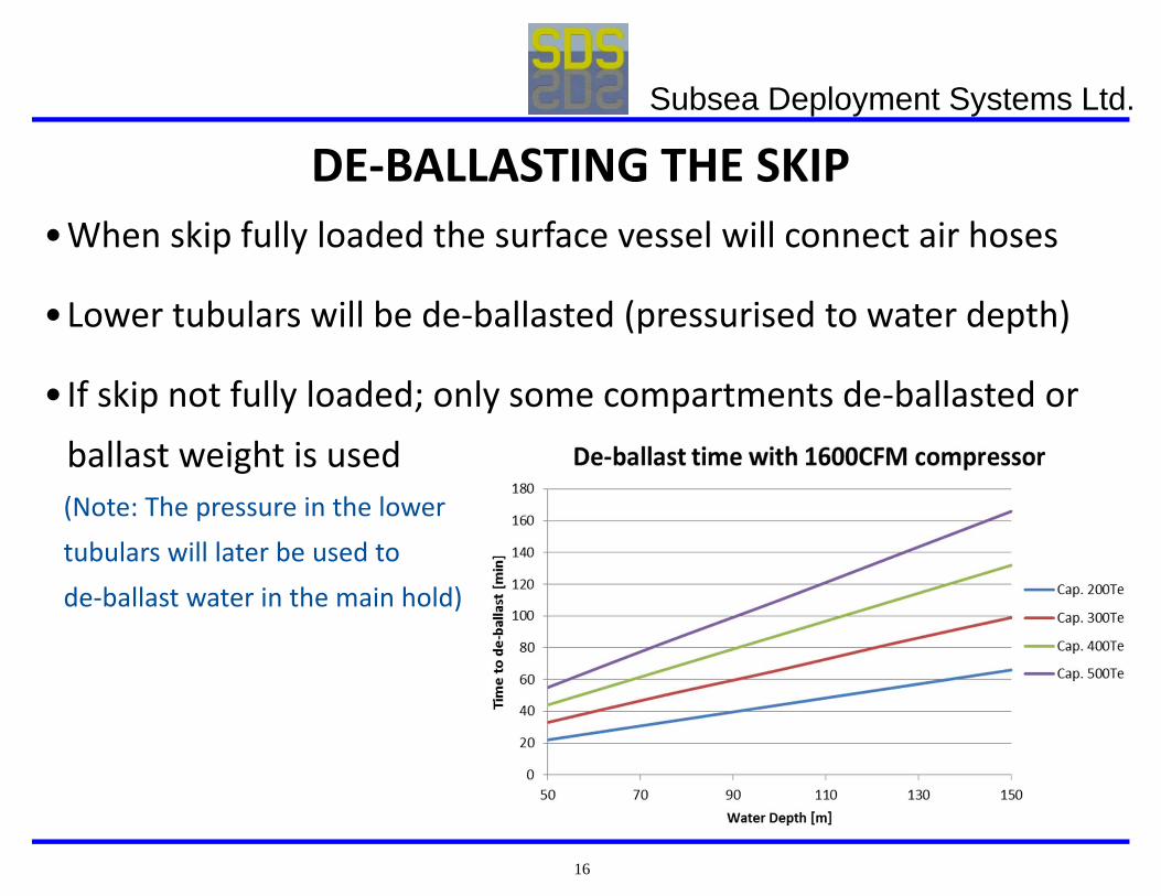
DE‐BALLASTING THE SKIP•When skip fully loaded the surface vessel will connect air hoses
•Lower tubulars will be de‐ballasted (pressurised to water depth)
•If skip not fully loaded; only some compartments de‐ballasted or ballast weight is used(Note: The pressure in the lowertubulars will later be used tode‐ballast water in the main hold)
Subsea Deployment Systems Ltd.
17
SKIP RECOVERY•The following measures ensure safe recovery of the skip
• Coarse weighing of each load by the crane• There is excess weight in the control chains to prevent early float‐off when de‐ballasting
• There is excess weight in the tow chain clump weight
•As the control chain are recovered the loaded skip rises off the seabed
•Once off the seabed, the load, trim & pitch are assessed
•If required, the skip would be re‐trimmed before starting the submerged tow
Subsea Deployment Systems Ltd.
18
SURFACING OF THE SKIP•Surfacing of skip would normally be done inshore in calm waters; however, it may be done offshore if weather permits
•The hold would be partitioned to ensure negligible shifting of payload during the surface tow
•During the submerged tow the skip is unaffected by the surface weather minimising roll and pitch
Subsea Deployment Systems Ltd.
19
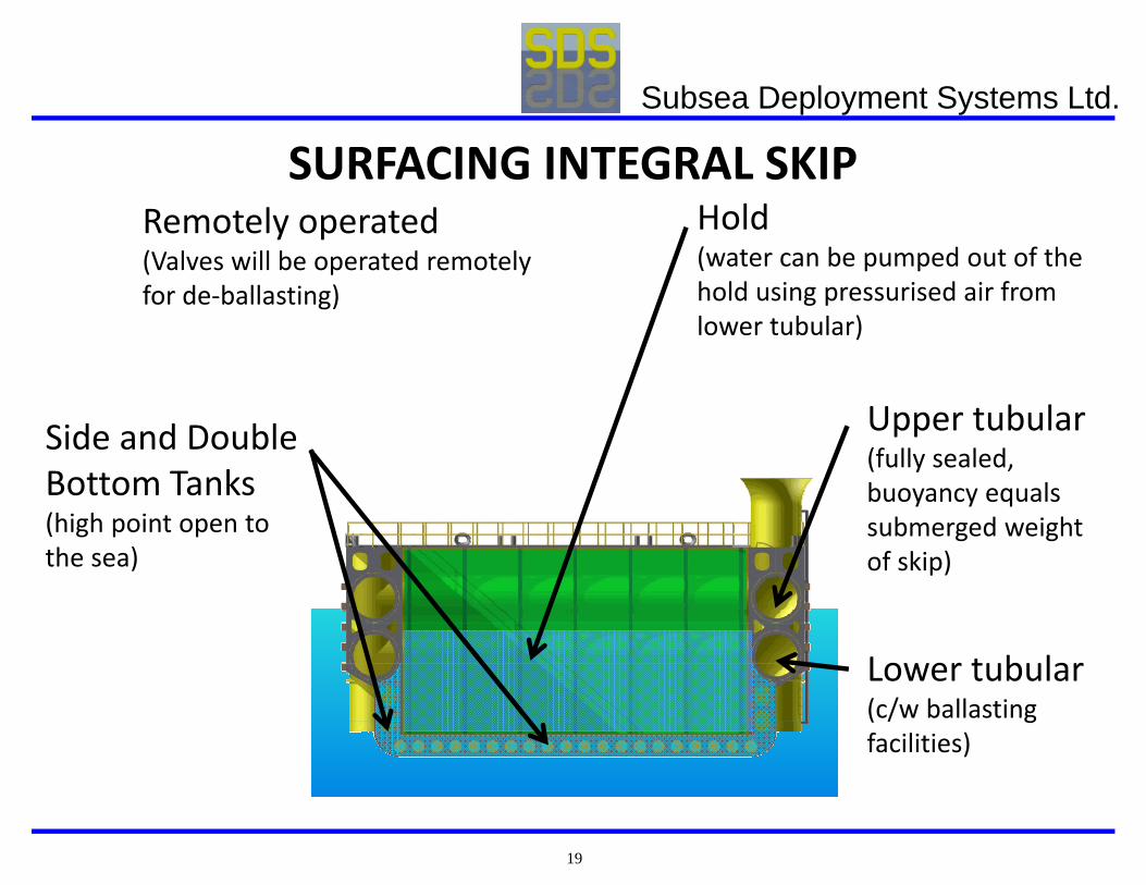
SURFACING INTEGRAL SKIP
Upper tubular (fully sealed, buoyancy equals submerged weight of skip)
Lower tubular (c/w ballasting facilities)
Side and Double Bottom Tanks (high point open to the sea)
Hold (water can be pumped out of the hold using pressurised air from lower tubular)
Remotely operated (Valves will be operated remotely for de‐ballasting)
Subsea Deployment Systems Ltd.
20
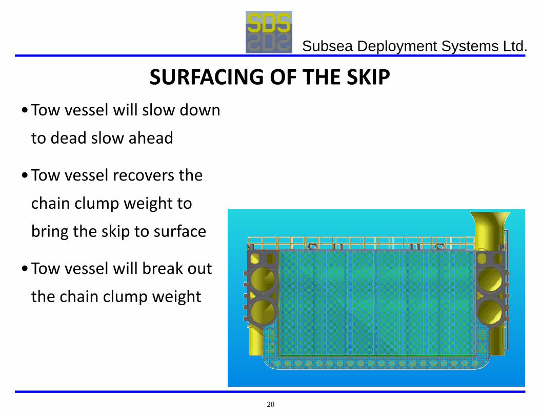
SURFACING OF THE SKIP•Tow vessel will slow down to dead slow ahead
•Tow vessel recovers the chain clump weight to bring the skip to surface
•Tow vessel will break out the chain clump weight
Subsea Deployment Systems Ltd.
21
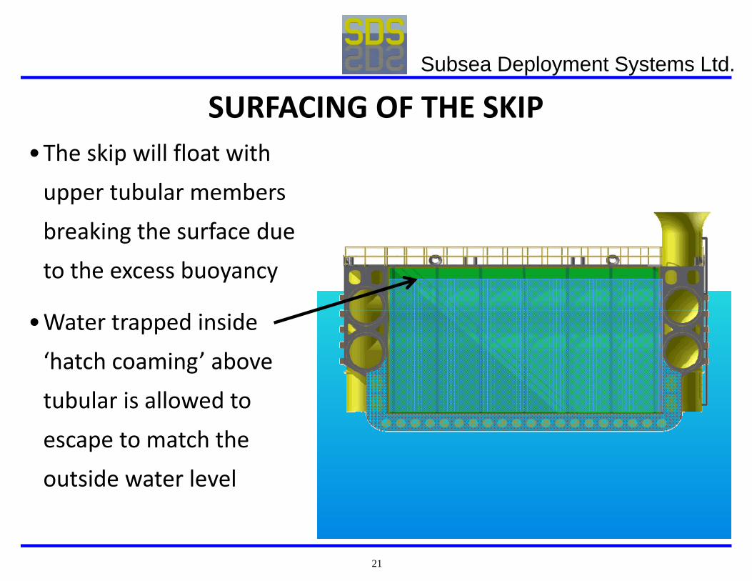
SURFACING OF THE SKIP•The skip will float with upper tubular members breaking the surface due to the excess buoyancy
•Water trapped inside ‘hatch coaming’ above tubular is allowed to escape to match the outside water level
Subsea Deployment Systems Ltd.
22
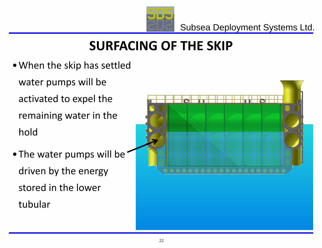
SURFACING OF THE SKIP•When the skip has settled water pumps will be activated to expel the remaining water in the hold
•The water pumps will be driven by the energy stored in the lower tubular
Subsea Deployment Systems Ltd.
23
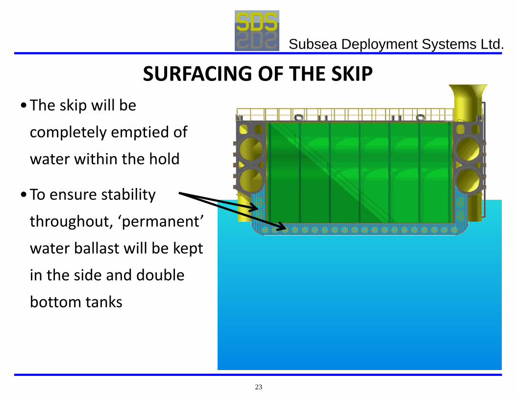
SURFACING OF THE SKIP•The skip will be completely emptied of water within the hold
•To ensure stability throughout, ‘permanent’ water ballast will be kept in the side and double bottom tanks
Subsea Deployment Systems Ltd.
24
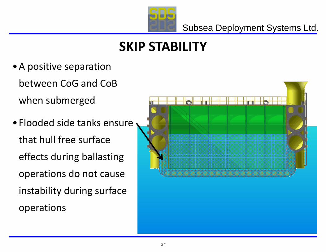
SKIP STABILITY•A positive separation between CoG and CoBwhen submerged
•Flooded side tanks ensure that hull free surface effects during ballasting operations do not cause instability during surface operations
Subsea Deployment Systems Ltd.
25
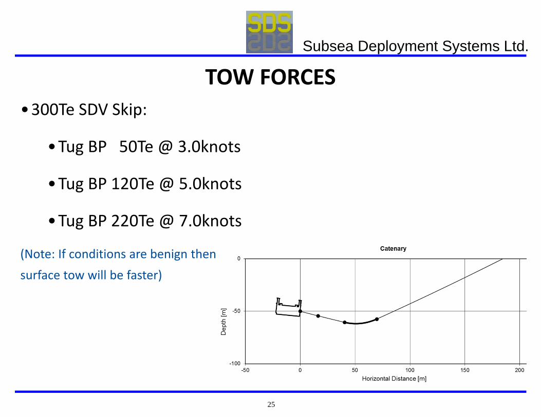
TOW FORCES•300Te SDV Skip:
•Tug BP 50Te @ 3.0knots
•Tug BP 120Te @ 5.0knots
•Tug BP 220Te @ 7.0knots
(Note: If conditions are benign then surface tow will be faster)
Subsea Deployment Systems Ltd.
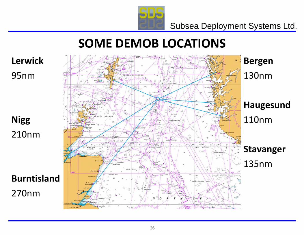
26
Lerwick95nm
Nigg210nm
Burntisland270nm
SOME DEMOB LOCATIONSBergen130nm
Haugesund110nm
Stavanger135nm
Subsea Deployment Systems Ltd.
27
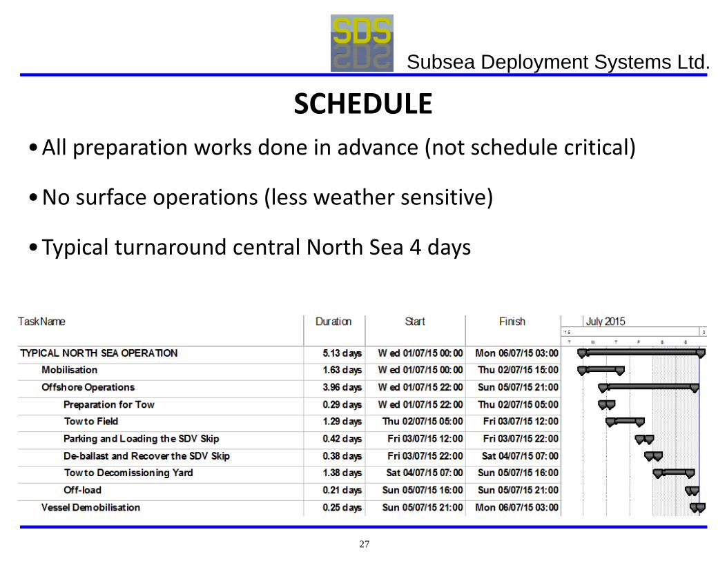
SCHEDULE•All preparation works done in advance (not schedule critical)
•No surface operations (less weather sensitive)
•Typical turnaround central North Sea 4 days
Subsea Deployment Systems Ltd.
28
CAPEX / OPEX•CAPEX
•300Te (wet) capacity approx. £1.5‐2.0m.
•OPEX
•AHT or Tug day rate vs. Construction Vessel time and weather downtime (can be significant when avoiding to recover to deck)
Subsea Deployment Systems Ltd.
29
SAFETY AND ENVIRONMENT•Low tech / fail safe
•Operations can be suspended at any time
•The overall operation is less sensitive weather
•Structures , spool pieces, mattresses etc. are not recovered to deck
•Reduces working and transit time for more costly vessel
Subsea Deployment Systems Ltd.