Embed Size (px)
Citation preview

1. INTRODUCTION
Recently, the advancement of broadband access systems is encouraging individual users to enjoy broad band ser-vices, and this is promoting further expansion of data communication networks. Among many access systems, the optical access system centered on FTTP (Fiber To The Premises) is playing a major role taking advantage of its superior communications throughput and immunity against external noise, and in particular, GE-PON (Gigabit Ethernet† Passive Optical Network) specified in IEEE 802.3 constitutes the mainstream. PON adopts a network architecture such that an optical transmission line from telecommunications providers is shared by multiple users, and is physically mid-branched to each user by using passive optical components. Therefore, the PON configu-ration is, as shown in Figure 1, categorized into point-to-multipoint (P2MP) network topology 1). This configuration involves a variety of asymmetry such as, for example, the distinction of upstream and downstream in a communica-tion system, and the difference in the number of line ter-minals installed on the telecommunications provider side
(i.e., optical line terminal, OLT) and on the subscriber side (i.e., optical network unit, ONU). When we focus our attention to the latter aspect, it may be possible for us to advantageously develop new GE-PON markets by impart-ing novelty to the ONU that occupies the majority side.
Furukawa Electric has long been involved with the research and development of optical sub-assemblies (OSAs) and optical transceiver modules on PMD (Physical Medium Dependent) sublayer 2), and is also marketing GE-PON-related products. In the development program here, after seeking the novelty mentioned above, we have identified beforehand a direction for development by merging our long-cultivated equipment technology and sublayer module technology. In this paper, individual ele-mental technologies will be described together with the characteristics of the developed product.
2. INTERNAL CONSTRUCTION AND ITS AIMS
It holds true for industrial products in general that, while those in the lower assembly level (i.e., parts) are mostly specified in their forms by the standards, equipment on which these parts and modules installed are less con-scious of specifications with respect to their forms. The same can be said of optical networks.
For optical transceivers in the sublayer of PHY (Physical Layer) and optical subassemblies like TOSA and ROSA, there are standards formulated by standardizing organi-zations, along with MSA (Multi Source Agreement) in which suppliers formulate standards as their common specifications 3). But, there are few discussions on the form of ONU as a CPE (Customer Premises Equipment). This may be justified from a viewpoint that places little significance on form as long as standardized input- and output-interfaces are equipped with. However, the present
SFP ONU as CPE for GE-PON
Nobuhiko Hattori *, Kunio Odaka *, Naoto Nakamura *, Kazutaka Shimoosako *2, Katsuya Aboshi *2
* FITEL-Photonics Lab., R&D Div. *2 Broadband Products Dept., Telecommunications Co.
† Ethernet is a registered trademark of Xerox Corporation.
Figure 1 System of PON architecture.
ONU
Downstream
OLT Upstream
Furukawa Review, No. 36 2009 6
In order to play a part in the expansion of data communication networks, we have developed ONU equipment for GE-PON in the form of SFP transceivers
that are standardized by the MSA. By simply mounting this ONU on any network equipment provided with an SFP interface port, it becomes possible to configure the integrated equipment under a GE-PON system. Since this equipment ensures high system reliability despite its simple implementation, it is expected that the equipment will be widely used in its best suited applications such as, for example, the line service for enterprises, and furthermore that it plays a role in developing new GE-PON markets. In this paper, its elementary technologies will be described and transmission characteristics etc. will be presented.
ABSTRACT
grated equipment under a GE-PON system. This leads to facilitating the introduction of a GE-PON system.
•PowersupplytothisONUcanbedonevianetworkequipment. In contrast to normal ONUs power of which is supplied via an AC adapter on a commercial power line, this contributes to enhancing system reli-ability.
Taking the security performance of GE-PON systems into consideration, the reliability of an application system that employs this ONU is high. Therefore, this ONU is best suited for such applications as, e.g., enterprise-targeted services and MDU (Multi Dwelling Unit) for complex hous-ings, and is expected to develop wide-ranging new GE-PON markets.
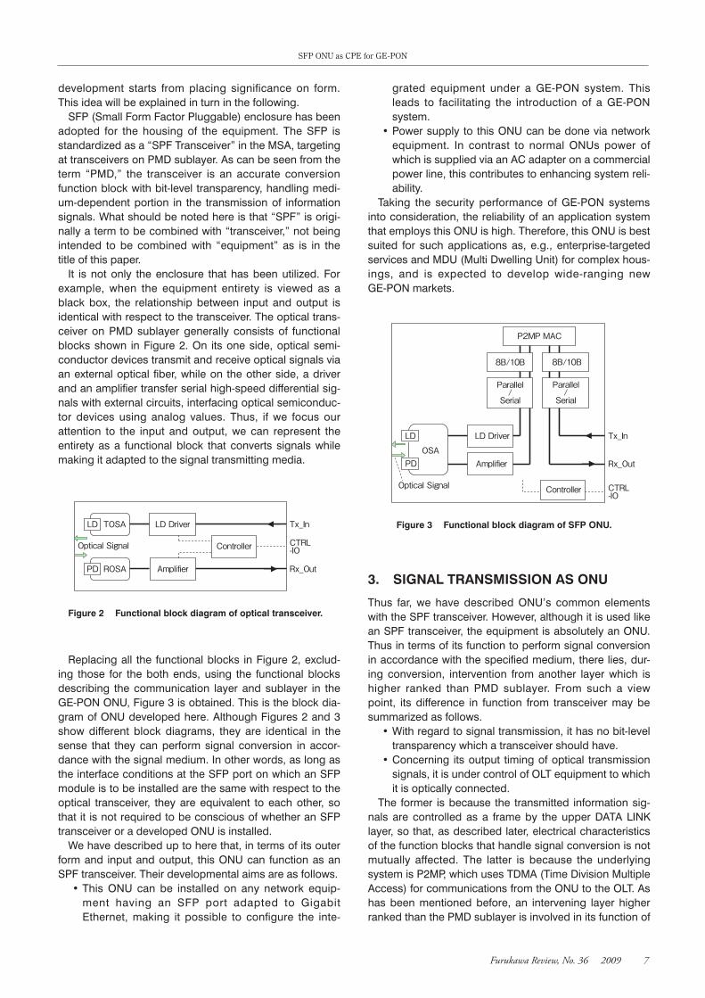
P2MP MAC
LD
OSA PD
LD Driver
Amplifier
Controller
Tx_In
Rx_Out
Parallel / Serial
8B/10B
Parallel / Serial
8B/10B
Optical Signal CTRL-IO
Figure 3 Functional block diagram of SFP ONU.
3. SIGNAL TRANSMISSION AS ONU
Thus far, we have described ONU’s common elements with the SPF transceiver. However, although it is used like an SPF transceiver, the equipment is absolutely an ONU. Thus in terms of its function to perform signal conversion in accordance with the specified medium, there lies, dur-ing conversion, intervention from another layer which is higher ranked than PMD sublayer. From such a view point, its difference in function from transceiver may be summarized as follows.•Withregardtosignaltransmission,ithasnobit-level
transparency which a transceiver should have.•Concerning itsoutput timingofoptical transmission
signals, it is under control of OLT equipment to which it is optically connected.
The former is because the transmitted information sig-nals are controlled as a frame by the upper DATA LINK layer, so that, as described later, electrical characteristics of the function blocks that handle signal conversion is not mutually affected. The latter is because the underlying system is P2MP, which uses TDMA (Time Division Multiple Access) for communications from the ONU to the OLT. As has been mentioned before, an intervening layer higher ranked than the PMD sublayer is involved in its function of
development starts from placing significance on form. This idea will be explained in turn in the following.
SFP (Small Form Factor Pluggable) enclosure has been adopted for the housing of the equipment. The SFP is standardized as a “SPF Transceiver” in the MSA, targeting at transceivers on PMD sublayer. As can be seen from the term “PMD,” the transceiver is an accurate conversion function block with bit-level transparency, handling medi-um-dependent portion in the transmission of information signals. What should be noted here is that “SPF” is origi-nally a term to be combined with “transceiver,” not being intended to be combined with “equipment” as is in the title of this paper.
It is not only the enclosure that has been utilized. For example, when the equipment entirety is viewed as a black box, the relationship between input and output is identical with respect to the transceiver. The optical trans-ceiver on PMD sublayer generally consists of functional blocks shown in Figure 2. On its one side, optical semi-conductor devices transmit and receive optical signals via an external optical fiber, while on the other side, a driver and an amplifier transfer serial high-speed differential sig-nals with external circuits, interfacing optical semiconduc-tor devices using analog values. Thus, if we focus our attention to the input and output, we can represent the entirety as a functional block that converts signals while making it adapted to the signal transmitting media.
LD TOSA
PD ROSA
LD Driver
Amplifier
Controller
Tx_In
Rx_Out
Optical Signal CTRL-IO
Figure 2 Functional block diagram of optical transceiver.
Replacing all the functional blocks in Figure 2, exclud-ing those for the both ends, using the functional blocks describing the communication layer and sublayer in the GE-PON ONU, Figure 3 is obtained. This is the block dia-gram of ONU developed here. Although Figures 2 and 3 show different block diagrams, they are identical in the sense that they can perform signal conversion in accor-dance with the signal medium. In other words, as long as the interface conditions at the SFP port on which an SFP module is to be installed are the same with respect to the optical transceiver, they are equivalent to each other, so that it is not required to be conscious of whether an SFP transceiver or a developed ONU is installed.
We have described up to here that, in terms of its outer form and input and output, this ONU can function as an SPF transceiver. Their developmental aims are as follows.•ThisONU can be installed on any network equip-
ment having an SFP port adapted to Gigabit Ethernet, making it possible to configure the inte-
Furukawa Review, No. 36 2009 7
SFP ONU as CPE for GE-PON

It should be pointed out here that in making such observations on this equipment, for the reasons men-tioned above, it is necessary to input electrical signals in the Ethernet frame format, as well as to make optical con-nection of the equipment with an OLT for GE-PON, plac-ing the equipment under control thereof. Unless these conditions are met, optical signals will not be transmitted. The same holds true in bit error rate measurements aimed at reliability testing of transmission signals, where it is impossible to make measurements by simply connecting a bit error tester as in the case of normal optical transceiv-ers. In such measurements, it is required to use an Ethernet tester or the like via a GE-PON OLT, as shown in Figure 6.
Ethernet Tester[ Traffic Generator/Analyzer ]
EPON-OLT[ 1000BASE-PX ]
EUT(SFP ONU)
OpticalAttenuator1000Base-LX
TestBoard
DownstreamUpstream
Figure 6 Test setup for measurement of signal transmission.
The reliability of signal transmission was evaluated in order to confirm the equipment function of signal conver-sion via the above-mentioned higher ranked layer. The test set up shown in Figure 6 was used, and the optical input level to this equipment from OLT was set to approxi-mately –20 dBm, so as not to be affected by the SNR (Signal to Noise Ratio) in the optical receiving circuit. The results are shown in Table 1, indicating that a sufficient level of reliability is achieved, i.e., of the order of 10–14 at least when converted in bit error rate.
Table 1 Results of transmission function test.
Count Item of Tester Downstream Upstream
Frames Sent 71,114,562,290 71,114,562,290
Valid Frames Received 71,114,562,290 71,114,562,290
Frames Loss Count 0 0
•FrameConstruction:8Bytes_Preamble+64Bytes
4. OPTICAL RECEIVING CHARACTER-ISTICS
In the field of optical network systems where optical sig-nals of extremely low levels are handled, it is essential, just like wireless systems, to suppress the crosstalk com-ponents caused by various signals below allowable limits so that they do not interfere as noise with the receiving
‒2 dBm
‒28 dBm
‒15 dBm
General Optical Transceiver SFP ONU Input Power
Figure 4 Waveform comparison of electrical output.
signal conversion. This means that the signals before and after conversion are isolated with each other. For exam-ple, when an optical signal of identical power is input to a normal optical transceiver and to this SPF ONU, and their signal waveforms are observed while changing their power, the difference can be seen as shown in Figure 4.
It can be seen that, in the case of normal optical trans-ceiver that is a PMD, when the optical input power is near its minimum operating value, a variation of timing in signal waveform occurs in the time axis under the influence of noise, while in the case of ONU equipment such variation can not be observed. The same holds for the reversed direction. When electrical signals with different amount of timing variation are input, as can be seen from Figure 5, no difference can be observed in the optical output sig-nals converted from each input. Thus, it can be under-stood that there is isolation.
( Optical Waveform ) Output
( Electrical Waveform ) Input
Figure 5 Waveform comparison of optical output.
Furukawa Review, No. 36 2009 8
SFP ONU as CPE for GE-PON

own optical transmitting signals, from which the interfer-ing components (2b in peak to peak) are derived, individ-ually occur with the same probability.
Meanwhile, optical beat noise between the transmission and receiving signals is not taken into account, since this lies outside the receiving bandwidth. It is also probable for optical crosstalk components within the OSA to reach the receiving device via multipath. In such a case, the fol-lowing two items need consideration, but neither of them is serious enough to abandon the model mentioned above. •Bittimescale
When one compares the size of an OSA with the one-bit time of GE-PON electric signal (i.e., 800 ps), one can reason that they can be consolidated into a single path.
•OpticalcarriertimescaleDepending on the phase summation of optical crosstalk components, the total crosstalk can be observed to have different intensities. In total, how-ever, so long as the model described here is con-cerned, the crosstalk for a single path can be used as an appropriate parameter.
a/σ=2.5
a/b=2.5
2a 2a σσ
2b 2b
2b 2b
2a: Received signal amplitude
2b: Optical crosstalk amplitude
2a: Received signal amplitude
2b: Optical crosstalk amplitude
Figure 8 Probability density distribution with optical crosstalk
For proper comparison of the two Figures, the ratio of signal amplitude to random noise intensity has not been changed. When the distribution crosses over the decision threshold value that is an average of “High“ and “Low“ used for amplitude decision, a wrong decision with respect to threshold value is made, resulting in occur-rence of bit errors. While this situation corresponds to the peak tail portion of the probability density distribution crossing over the threshold, it would be clearly under-stood, comparing the two Figures, that the existence of crosstalk in the OSA has increased the probability of crossing over the threshold. In order to verify the concept of recognizing the adverse influence of internal optical crosstalk, the degradation degree was obtained by simu-lation, and was compared with the measurements. The
circuit. Therefore, considerable work has been done until now addressing this issue. Moreover, the GE-PON system prescribes the use of single optical fiber to transmit bidi-rectional optical signals. In most cases this has led to, together with the requirement for size reduction, the use of an OSA module that integrates both the transmitting and receiving circuits for GE-PON optical transceiver modules. For such an integrated transmitting-receiving OSA module, theoretical research work is also done by developing a model to simulate the crosstalk between the transmitting and receiving terminals 4).
As is described in such a model, there exists a kind of crosstalk in an integrated transmitting-receiving OSA module, in which its own optical transmitting signals directly couple into the photodiode of the optical receiv-ing circuit. This type of crosstalk that depends on the internal structure of OSA can not be ignored in some cases, so that it is one of the important issues for design-ing an OSA. Accordingly, we investigated in advance the degradation of optical receiving characteristics due to this optical crosstalk within the OSA.
As shown in Figure 7, the theoretical model for the bit error in an ideal receiving circuit can generally be described by a probability density distribution with double peaks, in which random noise having Gaussian distribu-tion (σ) is superimposed on the signal (2a in peak to peak). Here, it is depicted that the signals “High” and “Low” included in the optical received signals each occurs with the same probability. However this model does not include optical crosstalk.
2a 2a σσ
a/σ=2.5
2a: Received signal amplitude2a: Received signal amplitude
Figure 7 Probability density distribution without optical cross-talk.
On the other hand, since optical crosstalk is an optical coupling to the optical receiving device, the photocurrent of the interference includes direct current components. In this case, each of the double-peaked distribution shown in Figure 7 shifts into a double-peaked distribution again. An example of probability density distribution for this case is shown in Figure 8. Here too, to set limits to the discus-sions, it is depicted that the signals "High" and "Low" in its
Furukawa Review, No. 36 2009 9
SFP ONU as CPE for GE-PON

the optical input power range mentioned above, bit error rate was measured by converting from measurements while inputting a fixed optical power of 0 dBm in Figure 6. The result is shown in Table 3. Meanwhile, in evaluating the optical receiving characteristics in this equipment one has to be somewhat careful in that, while, as mentioned before, this equipment has to be under control of an OLT for GE-PON in such evaluation measurement, the system limit in the upstream direction can be reached first depending on the setting conditions for optical insertion loss—this may have wavelength dependence—thus breaking the logical link with the OLT. For this reason, the optical transmission line in the GE-PON section should be separated based on wavelength, between the upstream and the downstream, and the insertion loss of the upstream transmission line is fixed at an approximately middle value.
Table 2 Receiver sensitivity at room temperature.
Item Value
Sample size 47
Range (dBm) –27.5 to –26.2
Average (dBm) –26.90
Std. Deviation (dB) 0.27
-29
-28
-27
-26
-25
-24
-23
70350Case temperature ( ℃ )
Receiver sensitivity ( dBm )
Specified value of IEEE802.3
Figure 10 Temperature dependence of receiver sensitivity.
Table 3 Evaluation results for the upper bound of receiving range at room temperature.
Item Value
Input Optical Power 0 dBm
Case Temperature 0 °C 35 °C 70 °C
Equivalent Bit Error Rate < 10–12 < 10–12 < 10–12
•SpecifiedvalueofIEEE802.3:–3dBm,Samplesize:n=5
From the results shown above, it can be seen that this equipment has a sufficient margin to meet the specifica-tions for 1000BASE-PX10U/20U specified in IEEE 802.3. This ONU equipment as an optical receiver has an addi-tional function beside that of outputting received Ethernet
0
1
2
3
4
5
6
7
-15 -12 -9 -6 -3 0 3Relative internal optical crosstalk (dB)
Penalty (dB)
SimulationTest Result
Figure 9 Effect of internal optical crosstalk.
results are shown in Figure 9, where the relative optical power is on the horizontal axis, and the reference level of0 dB is defined as the optical input power to obtain a bit error rate of 10–12 under the absence of internal optical crosstalk. Close agreement can be seen between the simulated and measurement results, thus confirming the validity of the degradation model.
In view of this simulation results, the target value for the allowable internal optical crosstalk in the OSA was set to around –10 dB, according to the index defined here.
When the downstream optical input signals contain other signals of different wavelengths that turn into optical crosstalk components, the way the distribution changes corresponding to the input signal power changes is differ-ent from that mentioned above, since the signal to inter-ference ratio remains constant no matter how the input signal power into the optical receiver changes. Also, the horizontal axis of Figure 9 no longer shows the signal to interference ratio. For this reason, Figure 9 can not be applied as it stands.
Until now, the effects of crosstalk on optical receiving characteristics have been presented. In the actual pro-cess of signal recovery, on the other hand, the clock recovery function block in this equipment functions after the amplitude is fixed using the decision threshold value. The function performance is generally argued on the basis of jitter that represents the amount of timing varia-tion of signal waveforms in the direction of time axis. However, in an ONU for GE-PON, the existence period for upstream signals becomes bursty, since the upstream relies on TDMA as mentioned before. So we have to be rather careful in discussing the influence of internal opti-cal crosstalk on jitter.
Let us move from the theoretical aspects discussed so far to the evaluation results of receiving characteristics. Here the optical receiver sensitivity is defined as the mini-mum optical input power level in Figure 6 corresponding to a bit error rate of 10–12 converted from the number of lost frames. Table 2 and Figure 10 show the receiver sen-sitivity measured with upstream signals transmitted with the maximum load, and the typical temperature depen-dence of such receiver sensitivity, respectively.
Also, with an intention of evaluating the upper bound of
Furukawa Review, No. 36 2009 10
SFP ONU as CPE for GE-PON

-2
-1
0
1
2
3
4
5
0 35 70Case temperature (°C)
Average launch power (dBm)
Specified value of IEEE802.3
4
6
8
10
12
14
16
18
20
0 35 70Case temperature (°C)
Extinction ratio (dB)
Specified value of IEEE802.3
0
20
40
60
80
100
0 3 5Case temperature (°C)
Eye mask margin (%)
7 0
Specified value of IEEE802.3
Figure 11 Temperature dependence of typical optical transmit-ting characteristics.
trend graph shown in Figure 13. The vertical axis has a scale of 2 mV/DIV, with its center line corresponding to 166 mV. The fluctuations shown in the Figure lie within ±1 DIV over the centerline, which is equivalent to less than ±0.05 dB.
Finally, let us briefly discuss jitter that represents the amount of timing variation of transmission optical signals in the time axis direction. Although, as noted before, the optical transmitting signals are bursty, their timing is syn-chronized with the clock for transmission in the ONU. Since this clock operates in continuous oscillation rather than in a bursty mode, the timing of optical burst signals is based on a stabilized clock, so that the jitter of the opti-cal transmitting signals in this ONU is basically equivalent to that of normal optical transmitter equipment, in terms of design concepts. Functional parts of optical burst signals during information transmission to the OLT were mea-sured for estimation of their jitter, and the results are
frames in the form of electrical signals, such that it receives signals to maintain a GE-PON link with an OLT, thereby continuing to stay under the control of the OLT. In this context, in order to evaluate the limiting point of GE-PON link, we have measured the minimum optical receiving power in Figure 6 needed to maintain a GE-PON link with an OLT. Table 4 shows the results. The GE-PON link is seen to be maintained down to a considerably lower power with respect to the receiver sensitivity above mentioned. In this measurement also, the downstream and the upstream of the GE-PON optical transmission line are separated so as to make the results reflect the optical receiving characteristics only.
Table 4 Evaluation results for the lower bound of GE-PON link at room temperature.
Item Value
Sample size 10
Range (dBm) –31.5 to –30.3
Average (dBm) –30.99
Std. Deviation (dB) 0.40
As has been noted above, satisfactory receiving char-acteristics have been obtained. Considering that this has been achieved with extremely compact equipment as this ONU, it can be thought that this is the fruit of our succes-sively accumulated technologies starting from the research and development of GE-PON-related OSAs and optical transceiver modules.
5. OPTICAL TRANSMITTING CHARAC-TERISTICS
Optical transmission signals are generated by the light emitting element, which is driven by the optical transmit-ting function block under the control of GE-PON system. Figure 11 shows the temperature dependence of typical optical transmitting characteristics, indicating that this equipment has a sufficient margin over the specifications for 1000BASE-PX10U/20U defined by IEEE 802.3.
In an ONU for GE-PON, the existence period for upstream optical signals becomes bursty, since the upstream relies on TDMA. We have observed the optical burst signals while randomly changing the information amount in the upstream direction, and the results are shown in Figure 12, in which the vertical direction repre-sents optical power. Comparisons of each optical power of burst signals indicate that they are stabilized exhibiting no change. In order to make quantitative evaluation, the averaged optical power in the burst span during a time period of 0.6 μs ~ 2.6 μs after rising burst was measured as an averaged electrical voltage. The measurements for 1000 sweeps are plotted on the vertical axis against the number of sweeps on the horizontal axis, resulting in a
Furukawa Review, No. 36 2009 11
SFP ONU as CPE for GE-PON

Figure 12 Launching burst signal from optical transmitter.
Figure 13 Trend chart of optical average launch power at the beginning of each burst span.
Bathtub curve Trend of 1000TJs
Figure 14 TJ measured in optical burst signals.
shown below. What is sought is TJ (Total Jitter) 1) specified at a BER of 10-12. Here, the TJ is derivered, as shown in Figure 14, based on the bathtub curve given by the mea-surement equipment. In the Figure, the upper plots stand for the bathtub curve (in brown) together with the trend (in blue) of 1000 TJs for each burst section, while the lower plots show the optical burst signal at a certain instant. The vertical axis of the trend graph has a scale of 10 ps/DIV, with its center line corresponding to 100 ps. The averaged TJ is calculated from the trend graph to be 104 ps. Comparison on a burst-to-burst basis shows that they are stabilized confirming sufficient characteristics. Considering anincrementaljitterthatisestimatedtobe+40ps,whichis inherent to jitter evaluation systems for optical burst sig-nals compared with those for continuously emitted optical signals, the TJ for this ONU is thought to be fully 65 ps.
6. CONCLUSIONS
We have developed a SFP ONU for GE-PON by applying the PMD sublayer technology. As can be seen from the fact that the enclosure for SFP transceivers is used, this equipment densely integrates the functions of ONU equip-ment into the size of an optical transceiver. This is about one eighties the volume of our normal ONUs, although a simple comparison may be difficult to make. Also this equipment is provided with a number of features integrat-ed in its simple form. It is expected that this equipment will take advantage of its features to play a role in devel-oping new GE-PON markets.
REFERENCES
1) IEEE Standard 802.3 - 2005 2) Iwase et al.: Optical Transceiver Modules for Gigabit Ethernet PON
FTTH System, Furukawa Review, No. 28, (2005), p. 8 3) Yuji Akatsu: Recent Progress in Optical Module and Transceiver
Technology, NTT Technical Review, Vol. 4, No. 10, (2006), p. 12 4) Mori et al.: An Optical Module for Optical Line Terminal on
155Mb/s and 622Mb/s Downstream ATM-PON Systems, Technical Report, IEICE, Vol. 100, No. 611, (2001), OCS2000-97, p. 37 (in Japanese)
Furukawa Review, No. 36 2009 12
SFP ONU as CPE for GE-PON