Embed Size (px)
Citation preview
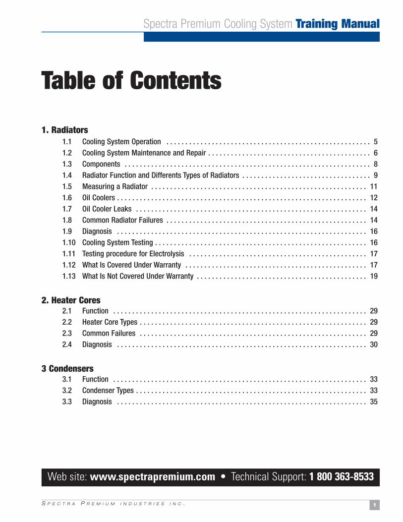
Spectra Premium Cooling System Training Manual
C o m p l e t e R a d i a t o r s • C o n d e n s e r s • H e a t e r s

S P E C T R A P R E M I U M I N D U S T R I E S I N C . 1
Table of Contents
1. Radiators1.1 Cooling System Operation . . . . . . . . . . . . . . . . . . . . . . . . . . . . . . . . . . . . . . . . . . . . . . . . . . . . . . 51.2 Cooling System Maintenance and Repair . . . . . . . . . . . . . . . . . . . . . . . . . . . . . . . . . . . . . . . . . . . 61.3 Components . . . . . . . . . . . . . . . . . . . . . . . . . . . . . . . . . . . . . . . . . . . . . . . . . . . . . . . . . . . . . . . . . 81.4 Radiator Function and Differents Types of Radiators . . . . . . . . . . . . . . . . . . . . . . . . . . . . . . . . . . 91.5 Measuring a Radiator . . . . . . . . . . . . . . . . . . . . . . . . . . . . . . . . . . . . . . . . . . . . . . . . . . . . . . . . . 111.6 Oil Coolers . . . . . . . . . . . . . . . . . . . . . . . . . . . . . . . . . . . . . . . . . . . . . . . . . . . . . . . . . . . . . . . . . . 12 1.7 Oil Cooler Leaks . . . . . . . . . . . . . . . . . . . . . . . . . . . . . . . . . . . . . . . . . . . . . . . . . . . . . . . . . . . . . 14 1.8 Common Radiator Failures . . . . . . . . . . . . . . . . . . . . . . . . . . . . . . . . . . . . . . . . . . . . . . . . . . . . . 141.9 Diagnosis . . . . . . . . . . . . . . . . . . . . . . . . . . . . . . . . . . . . . . . . . . . . . . . . . . . . . . . . . . . . . . . . . . 16 1.10 Cooling System Testing . . . . . . . . . . . . . . . . . . . . . . . . . . . . . . . . . . . . . . . . . . . . . . . . . . . . . . . . 161.11 Testing procedure for Electrolysis . . . . . . . . . . . . . . . . . . . . . . . . . . . . . . . . . . . . . . . . . . . . . . . 171.12 What Is Covered Under Warranty . . . . . . . . . . . . . . . . . . . . . . . . . . . . . . . . . . . . . . . . . . . . . . . . 171.13 What Is Not Covered Under Warranty . . . . . . . . . . . . . . . . . . . . . . . . . . . . . . . . . . . . . . . . . . . . . 19
2. Heater Cores2.1 Function . . . . . . . . . . . . . . . . . . . . . . . . . . . . . . . . . . . . . . . . . . . . . . . . . . . . . . . . . . . . . . . . . . . 292.2 Heater Core Types . . . . . . . . . . . . . . . . . . . . . . . . . . . . . . . . . . . . . . . . . . . . . . . . . . . . . . . . . . . . 292.3 Common Failures . . . . . . . . . . . . . . . . . . . . . . . . . . . . . . . . . . . . . . . . . . . . . . . . . . . . . . . . . . . . 292.4 Diagnosis . . . . . . . . . . . . . . . . . . . . . . . . . . . . . . . . . . . . . . . . . . . . . . . . . . . . . . . . . . . . . . . . . . 30
3 Condensers3.1 Function . . . . . . . . . . . . . . . . . . . . . . . . . . . . . . . . . . . . . . . . . . . . . . . . . . . . . . . . . . . . . . . . . . . 333.2 Condenser Types . . . . . . . . . . . . . . . . . . . . . . . . . . . . . . . . . . . . . . . . . . . . . . . . . . . . . . . . . . . . . 333.3 Diagnosis . . . . . . . . . . . . . . . . . . . . . . . . . . . . . . . . . . . . . . . . . . . . . . . . . . . . . . . . . . . . . . . . . . 35
Spectra Premium Cooling System Training Manual
Web site: www.spectrapremium.com • Technical Support: 1 800 363-8533

A R E T H E O N L Y C H O I C EWHY SPECTRA PREMIUM
RADIATORSA R E T H E O N L Y C H O I C E
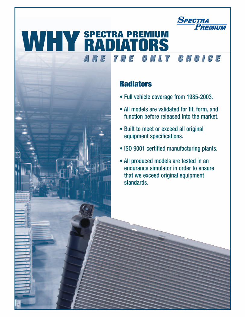
Radiators
• Full vehicle coverage from 1985-2003.
• All models are validated for fit, form, andfunction before released into the market.
• Built to meet or exceed all originalequipment specifications.
• ISO 9001 certified manufacturing plants.
• All produced models are tested in anendurance simulator in order to ensure that we exceed original equipmentstandards.

S P E C T R A P R E M I U M I N D U S T R I E S I N C . 5
Spectra Premium Cooling System Training Manual
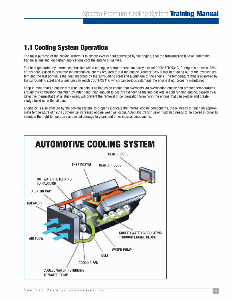
1.1 Cooling System OperationThe main purpose of the cooling system is to absorb excess heat generated by the engine, cool the transmission fluid on automatictransmissions and, on certain applications cool the engine oil as well.
The heat generated by internal combustion within an engine compartment can easily exceed 2000o F/1093o C. During this process, 33%of this heat is used to generate the mechanical energy required to run the engine. Another 33% is lost heat going out of the exhaust sys-tem and the last portion is the heat absorbed by the surrounding steel and aluminium of the engine. The temperature that is absorbed bythe surrounding steel and aluminum can reach 700o F/371o C which can seriously damage the engine if not properly maintained.
Keep in mind that an engine that runs too cold is as bad as an engine that overheats. An overheating engine can produce temperaturesaround the combustion chamber (cylinder head) high enough to destroy cylinder heads and gaskets. A cold running engine, caused by adefective thermostat that is stuck open, will prevent the removal of condensation forming in the engine that can oxidize and createsludge build up in the oil pan.
Engine oil is also affected by the cooling system. To properly lubricate the internal engine components, the oil needs to reach an approxi-mate temperature of 190o F; otherwise increased engine wear will occur. Automatic transmission fluid also needs to be cooled in order tomaintain the right temperature and avoid damage to gears and other internal components.
AUTOMOTIVE COOLING SYSTEM
THERMOSTAT
HEATER CORE
HEATER HOSES
HOT WATER RETURNING TO RADIATOR
RADIATOR CAP
RADIATOR
AIR FLOW
COOLED WATER RETURNINGTO WATER PUMP
COOLING FAN
BELTWATER PUMP
COOLED WATER CIRCULATINGTHROUGH ENGINE BLOCK
S P E C T R A P R E M I U M I N D U S T R I E S I N C .6
Spectra Premium Cooling System Training Manual
When replacing a radiator
Many reasons cause a radiator to fail. Finding the real cause will surely reduce shop comebacks. Here are a few steps that will help prevent comebacks.
1- Always ask yourself what caused the radiator to fail.Check all possible causes for the radiator deterioration.
2- Inspect radiator cap with tester.The radiator cap increases the boiling point of the coolant and ensures a constant level of coolant in the radiator.
3- Thoroughly flush the system including the heater core and overflow container.Any residue in the system may contaminate the new coolant and cause premature failure.
4- Install a new thermostat.Keeping the temperature right is what it’s all about… install the right temperature range thermostat.
5- Inspect hoses and install new clamps.
6- 50/50 mix of antifreeze and clean water (distilled water is recommended if water treatment in the region shows high signs of by-products).This mix will provide protection against boiling and freezing temperatures while providing maximum corrosion protection.
7- Once the work is completed, run the engine long enough for the electric cooling fans to turn on or inspect the mechanical thermalclutch fan for proper engagement.Cooling fans are crucial for proper system operation and preventing cooling problems at low speeds. For electric coolingfans, see manufacturer specification in the shop manual as most vehicles use the on-board computer via the enginecoolant temperature sensor to turn on the fans.
8- Ensure the drive belts, specially the one that runs the water pump is tight and in good condition.
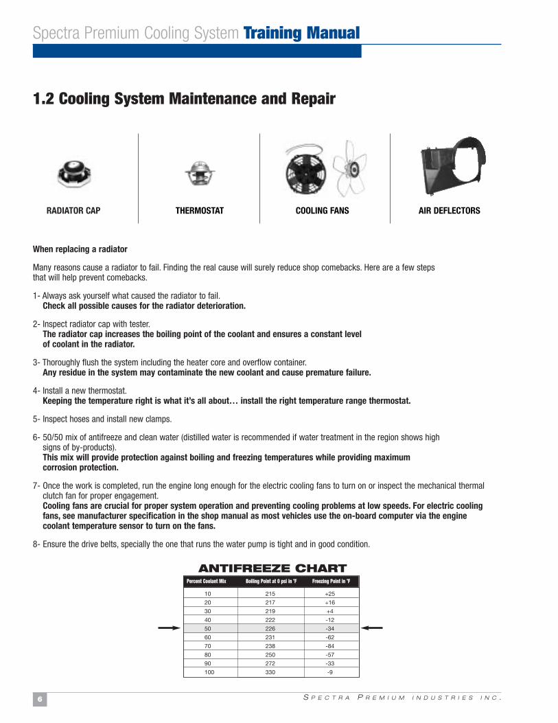
RADIATOR CAP THERMOSTAT AIR DEFLECTORSCOOLING FANS
10 215 +25
20 217 +16
30 219 +4
40 222 -12
50 226 -34
60 231 -62
70 238 -84
80 250 -57
90 272 -33
100 330 -9
Percent Coolant Mix Boiling Point at 0 psi in oF Freezing Point in oF
ANTIFREEZE CHART
1.2 Cooling System Maintenance and Repair
S P E C T R A P R E M I U M I N D U S T R I E S I N C . 7
Radiator CapThe radiator cap is used to control cooling system pressure and coolant recovery. The cap is spring-loaded to the manufacturer specifica-tion that varies between 5 and 15 Psi. This pressure is used to increase the boiling point of the coolant and prevent vapor build uparound the engine. As vapor is the last step in the change of state for a liquid, vapor cannot absorb anymore heat. Depending where thevapor will be located in the engine (usually on the upper portion, near the cylinder heads where the combustion occurs), this will causethe temperature around those components to rise beyond thermal breakdown. A defective radiator cap can easily damage radiator tanksif system pressure exceeds manufacturer specification.
ThermostatThe thermostat is mounted on the upper part of the engine usually near the cylinder heads. The thermostat incorporates a heat-sensingpellet that will cause the opening of a passage to the radiator. The sensing pellet is filled with wax impregnated of copper that willexpand when heated and contract when cooled. When the sensing pellet warms up, it will act on the piston and open the valve that willlet the coolant flow to the radiator. When the temperature is below the opening threshold, the thermostat is closed and coolant only circu-lates in the engine to absorb more heat. Coolant is also directed to the heater core. When the thermostat is opened, hot-soaked coolantwill flow through the thermostat to the upper radiator hose and into the radiator. At the same time, cooled liquid that was in the radiatorreturns to the engine by the lower radiator hose ready to start the cycle over again.
Cooling FansThe cooling fans are used to force the air through the radiator to accelerate heat exchange and cool the liquid. Cooling fans can be drivendirectly by the engine or driven by an electric motor. Cooling fans must be inspected on a regular basis and especially during radiator orcondenser replacement.
Deflector baffles and Shrouds Baffles and fan shrouds are designed to insure maximum airflow through the radiator and increasing cooling. Baffles are usually mountedin the front and below the radiator so a ram air effect is created. Missing baffles will cause a portion of the air to by-pass the radiatorand reduce cooling. All missing baffles must be replaced. On vehicles with low profile front ends, a lower radiator air deflector will carrythe air upwards insures airflow to the radiator. If the air deflector is missing, overheat condition will occur at speeds over 30 mph(50kmh).
Water PumpThe water is used to circulate coolant in the system. The coolant is circulated around the cylinder’s water jackets and heater core. Whenthe coolant has reached a certain temperature, the water pump will push the coolant into the radiator where it will be cooled andreturned to the engine. The water pump depends on the antifreeze ability to lubricate the seals and extend pump life. Corrosion in thesystem, will breakdown the water pump metallic impellers and reduce coolant circulation in the system.
CoolantCoolant must be replaced at recommended intervals. A 50/50 mix of water and antifreeze will insure maximum system protection againstfreezing and overheating conditions. When a cooling system is serviced, a thorough cleaning of the system is imperative. Any traces ofold coolant in the system can reduce corrosion inhibitor ability to protect the new replacement components. Test coolant pH level andelectrolysis during regular vehicle maintenance.
Spectra Premium Cooling System Training Manual
1.2 Cooling System Maintenance and Repair (cont’d)
S P E C T R A P R E M I U M I N D U S T R I E S I N C .8
Spectra Premium Cooling System Training Manual
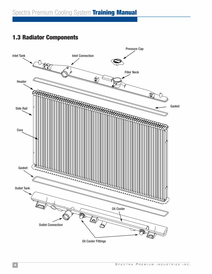
1.3 Radiator Components
Pressure Cap
Filler Neck
Gasket
Gasket
Outlet Tank
Outlet Connection
Oil Cooler Fittings
Oil Cooler
Inlet ConnectionInlet Tank
Header
Side Rail
Core
S P E C T R A P R E M I U M I N D U S T R I E S I N C . 9
1.4 Radiator Function and Types of Radiators
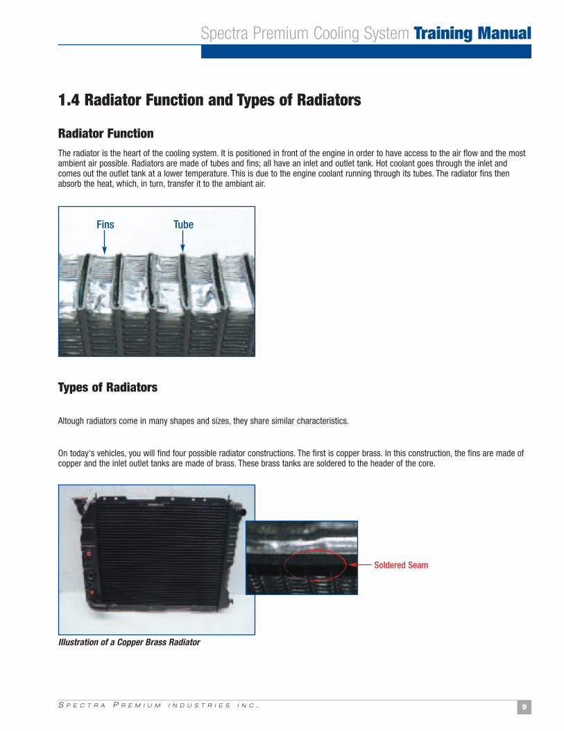
Radiator FunctionThe radiator is the heart of the cooling system. It is positioned in front of the engine in order to have access to the air flow and the mostambient air possible. Radiators are made of tubes and fins; all have an inlet and outlet tank. Hot coolant goes through the inlet andcomes out the outlet tank at a lower temperature. This is due to the engine coolant running through its tubes. The radiator fins thenabsorb the heat, which, in turn, transfer it to the ambiant air.
Types of Radiators
Altough radiators come in many shapes and sizes, they share similar characteristics.
On today's vehicles, you will find four possible radiator constructions. The first is copper brass. In this construction, the fins are made ofcopper and the inlet outlet tanks are made of brass. These brass tanks are soldered to the header of the core.
Spectra Premium Cooling System Training Manual
Fins Tube
Soldered Seam
Illustration of a Copper Brass Radiator
S P E C T R A P R E M I U M I N D U S T R I E S I N C .10
Spectra Premium Cooling System Training Manual
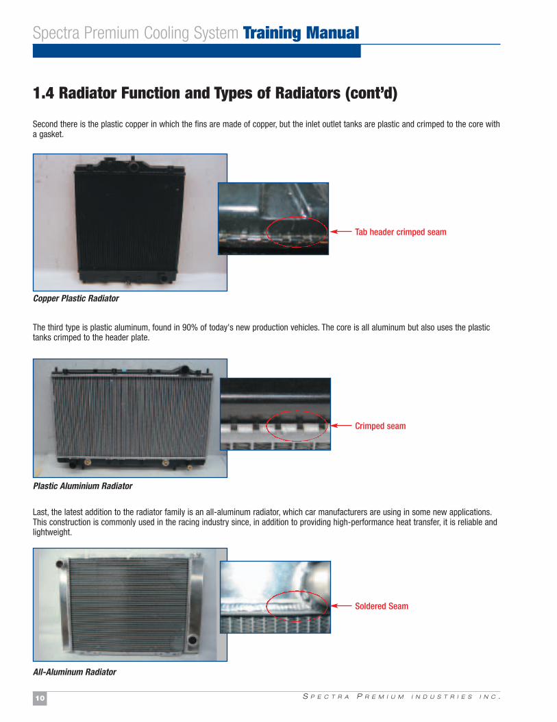
Crimped seam
Soldered Seam
Tab header crimped seam
Plastic Aluminium Radiator
All-Aluminum Radiator
Copper Plastic Radiator
1.4 Radiator Function and Types of Radiators (cont’d)
Second there is the plastic copper in which the fins are made of copper, but the inlet outlet tanks are plastic and crimped to the core witha gasket.
The third type is plastic aluminum, found in 90% of today's new production vehicles. The core is all aluminum but also uses the plastictanks crimped to the header plate.
Last, the latest addition to the radiator family is an all-aluminum radiator, which car manufacturers are using in some new applications.This construction is commonly used in the racing industry since, in addition to providing high-performance heat transfer, it is reliable andlightweight.
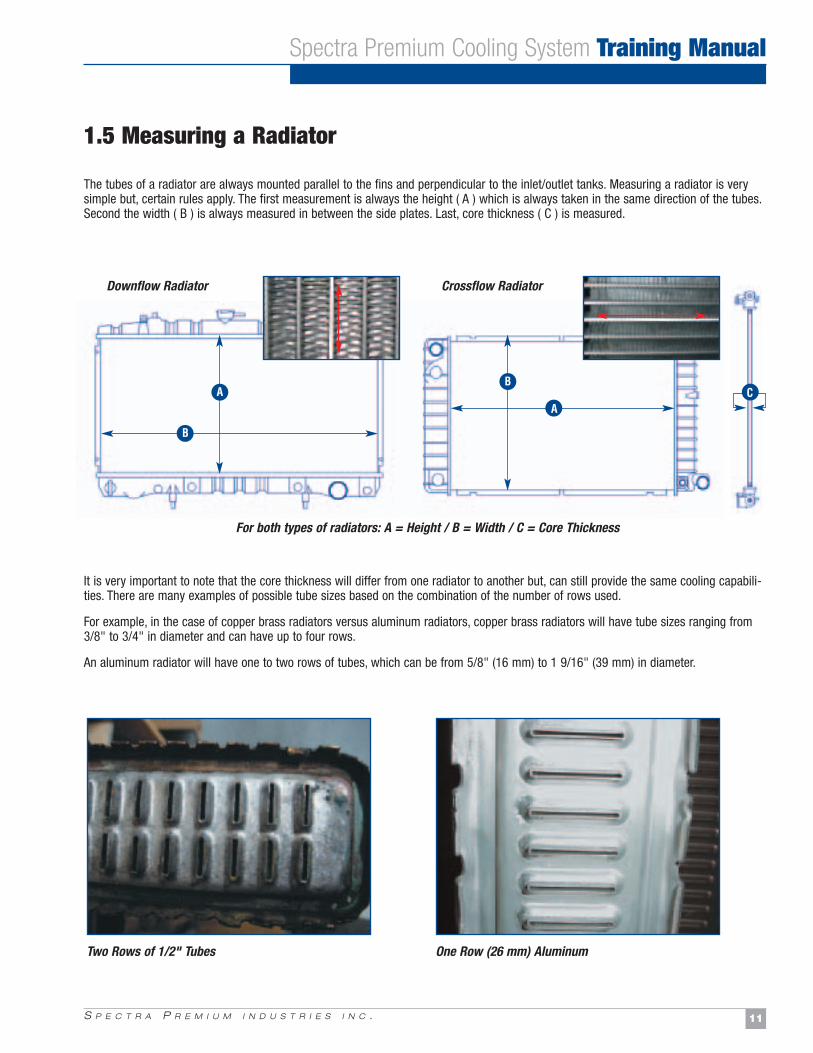
The tubes of a radiator are always mounted parallel to the fins and perpendicular to the inlet/outlet tanks. Measuring a radiator is verysimple but, certain rules apply. The first measurement is always the height ( A ) which is always taken in the same direction of the tubes.Second the width ( B ) is always measured in between the side plates. Last, core thickness ( C ) is measured.
It is very important to note that the core thickness will differ from one radiator to another but, can still provide the same cooling capabili-ties. There are many examples of possible tube sizes based on the combination of the number of rows used.
For example, in the case of copper brass radiators versus aluminum radiators, copper brass radiators will have tube sizes ranging from3/8" to 3/4" in diameter and can have up to four rows.
An aluminum radiator will have one to two rows of tubes, which can be from 5/8" (16 mm) to 1 9/16" (39 mm) in diameter.
S P E C T R A P R E M I U M I N D U S T R I E S I N C . 11
Spectra Premium Cooling System Training Manual
AB
A
B
C
Two Rows of 1/2" Tubes One Row (26 mm) Aluminum
Downflow Radiator
For both types of radiators: A = Height / B = Width / C = Core Thickness
Crossflow Radiator
1.5 Measuring a Radiator
S P E C T R A P R E M I U M I N D U S T R I E S I N C .12
Spectra Premium Cooling System Training Manual
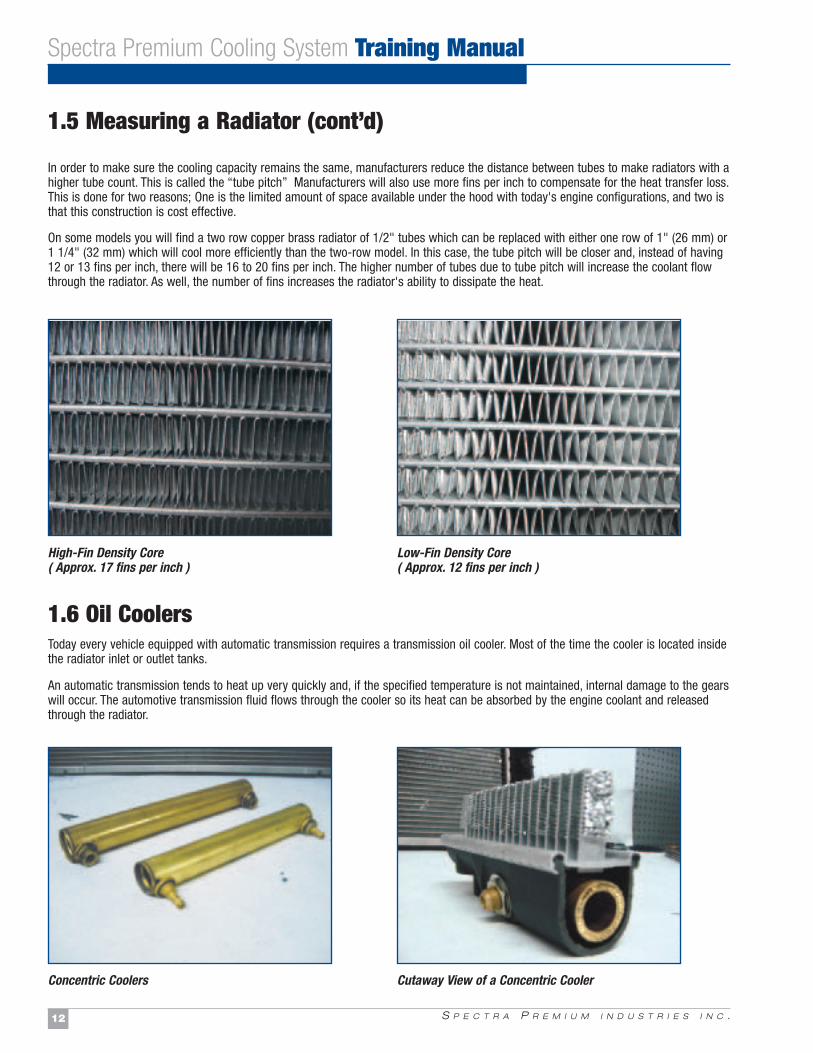
High-Fin Density Core( Approx. 17 fins per inch )
Low-Fin Density Core( Approx. 12 fins per inch )
Concentric Coolers Cutaway View of a Concentric Cooler
1.5 Measuring a Radiator (cont’d)
1.6 Oil CoolersToday every vehicle equipped with automatic transmission requires a transmission oil cooler. Most of the time the cooler is located insidethe radiator inlet or outlet tanks.
An automatic transmission tends to heat up very quickly and, if the specified temperature is not maintained, internal damage to the gearswill occur. The automotive transmission fluid flows through the cooler so its heat can be absorbed by the engine coolant and releasedthrough the radiator.
In order to make sure the cooling capacity remains the same, manufacturers reduce the distance between tubes to make radiators with ahigher tube count. This is called the “tube pitch” Manufacturers will also use more fins per inch to compensate for the heat transfer loss.This is done for two reasons; One is the limited amount of space available under the hood with today's engine configurations, and two isthat this construction is cost effective.
On some models you will find a two row copper brass radiator of 1/2" tubes which can be replaced with either one row of 1" (26 mm) or1 1/4" (32 mm) which will cool more efficiently than the two-row model. In this case, the tube pitch will be closer and, instead of having12 or 13 fins per inch, there will be 16 to 20 fins per inch. The higher number of tubes due to tube pitch will increase the coolant flowthrough the radiator. As well, the number of fins increases the radiator's ability to dissipate the heat.
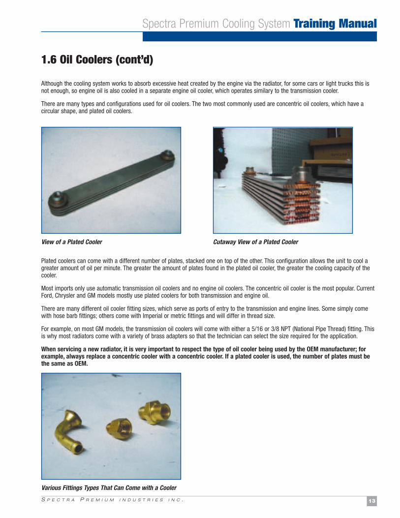
Although the cooling system works to absorb excessive heat created by the engine via the radiator, for some cars or light trucks this isnot enough, so engine oil is also cooled in a separate engine oil cooler, which operates similary to the transmission cooler.
There are many types and configurations used for oil coolers. The two most commonly used are concentric oil coolers, which have a circular shape, and plated oil coolers.
Plated coolers can come with a different number of plates, stacked one on top of the other. This configuration allows the unit to cool agreater amount of oil per minute. The greater the amount of plates found in the plated oil cooler, the greater the cooling capacity of thecooler.
Most imports only use automatic transmission oil coolers and no engine oil coolers. The concentric oil cooler is the most popular. CurrentFord, Chrysler and GM models mostly use plated coolers for both transmission and engine oil.
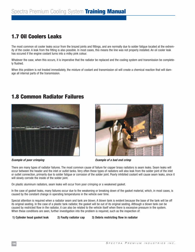
There are many different oil cooler fitting sizes, which serve as ports of entry to the transmission and engine lines. Some simply comewith hose barb fittings; others come with Imperial or metric fittings and will differ in thread size.
For example, on most GM models, the transmission oil coolers will come with either a 5/16 or 3/8 NPT (National Pipe Thread) fitting. Thisis why most radiators come with a variety of brass adapters so that the technician can select the size required for the application.
When servicing a new radiator, it is very important to respect the type of oil cooler being used by the OEM manufacturer; forexample, always replace a concentric cooler with a concentric cooler. If a plated cooler is used, the number of plates must bethe same as OEM.
S P E C T R A P R E M I U M I N D U S T R I E S I N C . 13
Spectra Premium Cooling System Training Manual
View of a Plated Cooler Cutaway View of a Plated Cooler
Various Fittings Types That Can Come with a Cooler
1.6 Oil Coolers (cont’d)
S P E C T R A P R E M I U M I N D U S T R I E S I N C .14
Spectra Premium Cooling System Training Manual
1.7 Oil Coolers Leaks
The most common oil cooler leaks occur from the brazed joints and fittings, and are normally due to solder fatigue located at the extrem-ity of the cooler. A leak from the fitting is also possible. In most cases, this means the line was not properly installed. An oil cooler leakhas occured if the engine coolant turns into a milky pink colour.
Whatever the case, when this occurs, it is imperative that the radiator be replaced and the cooling system and transmission be complete-ly flushed.
When this problem is not treated immediately, the mixture of coolant and transmission oil will create a chemical reaction that will dam-age all internal parts of the transmission.
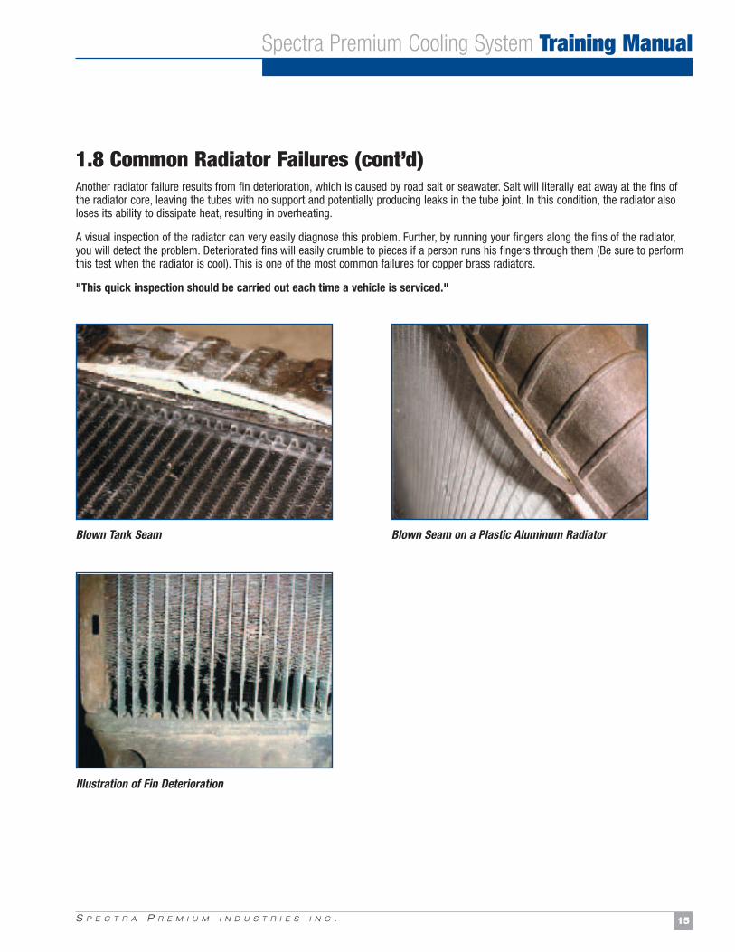
Example of poor crimping Example of a bad end crimp
1.8 Common Radiator Failures
There are many types of radiator failures. The most common cause of failure for copper brass radiators is seam leaks. Seam leaks willoccur between the header and the inlet or outlet tanks. Very often these types of radiators will also leak from the solder joint of the inletor outlet connection, primarily due to solder fatigue or corrosion of the solder joint. Poorly inhibited coolant will cause seam leaks, since itwill slowly corrode the inside of the solder joint.
On plastic aluminum radiators, seam leaks will occur from poor crimping or a weakened gasket.
In the case of gasket leaks, many failures occur due to the weakening or breaking down of the gasket material, which, in most cases, iscaused by the constant change in operating temperatures in the vehicle over time.
Special attention is required when a radiator seam and tank are blown. A blown tank is evident because the base of the tank will be offits original seating. In the case of a plastic tank radiator, the gasket will be out of its original seating. Although a blown tank can becaused by restricted flow in the radiator, it can also be related to the vehicle itself when there is excessive pressure in the system.When these conditions are seen, further investigation into the problem is required, such as the inspection of:
1) Cylinder head gasket leak 2) Faulty radiator cap 3) Debris restricting flow in radiator
S P E C T R A P R E M I U M I N D U S T R I E S I N C . 15
Spectra Premium Cooling System Training Manual
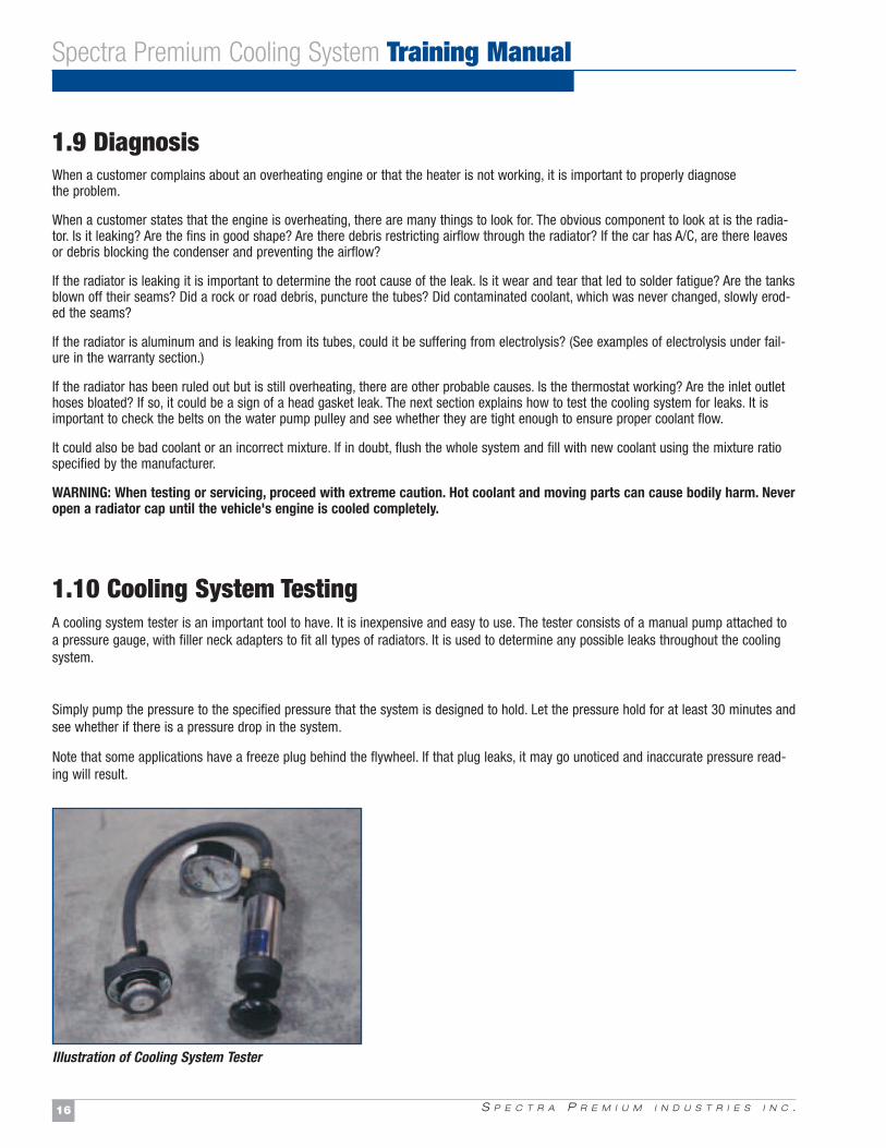
1.8 Common Radiator Failures (cont’d)Another radiator failure results from fin deterioration, which is caused by road salt or seawater. Salt will literally eat away at the fins ofthe radiator core, leaving the tubes with no support and potentially producing leaks in the tube joint. In this condition, the radiator alsoloses its ability to dissipate heat, resulting in overheating.
A visual inspection of the radiator can very easily diagnose this problem. Further, by running your fingers along the fins of the radiator,you will detect the problem. Deteriorated fins will easily crumble to pieces if a person runs his fingers through them (Be sure to performthis test when the radiator is cool). This is one of the most common failures for copper brass radiators.
"This quick inspection should be carried out each time a vehicle is serviced."
Blown Tank Seam Blown Seam on a Plastic Aluminum Radiator
Illustration of Fin Deterioration
S P E C T R A P R E M I U M I N D U S T R I E S I N C .16
Spectra Premium Cooling System Training Manual
1.9 DiagnosisWhen a customer complains about an overheating engine or that the heater is not working, it is important to properly diagnose the problem.
When a customer states that the engine is overheating, there are many things to look for. The obvious component to look at is the radia-tor. Is it leaking? Are the fins in good shape? Are there debris restricting airflow through the radiator? If the car has A/C, are there leavesor debris blocking the condenser and preventing the airflow?
If the radiator is leaking it is important to determine the root cause of the leak. Is it wear and tear that led to solder fatigue? Are the tanksblown off their seams? Did a rock or road debris, puncture the tubes? Did contaminated coolant, which was never changed, slowly erod-ed the seams?
If the radiator is aluminum and is leaking from its tubes, could it be suffering from electrolysis? (See examples of electrolysis under fail-ure in the warranty section.)
If the radiator has been ruled out but is still overheating, there are other probable causes. Is the thermostat working? Are the inlet outlethoses bloated? If so, it could be a sign of a head gasket leak. The next section explains how to test the cooling system for leaks. It isimportant to check the belts on the water pump pulley and see whether they are tight enough to ensure proper coolant flow.
It could also be bad coolant or an incorrect mixture. If in doubt, flush the whole system and fill with new coolant using the mixture ratiospecified by the manufacturer.
WARNING: When testing or servicing, proceed with extreme caution. Hot coolant and moving parts can cause bodily harm. Neveropen a radiator cap until the vehicle's engine is cooled completely.
1.10 Cooling System TestingA cooling system tester is an important tool to have. It is inexpensive and easy to use. The tester consists of a manual pump attached toa pressure gauge, with filler neck adapters to fit all types of radiators. It is used to determine any possible leaks throughout the coolingsystem.
Simply pump the pressure to the specified pressure that the system is designed to hold. Let the pressure hold for at least 30 minutes andsee whether if there is a pressure drop in the system.
Note that some applications have a freeze plug behind the flywheel. If that plug leaks, it may go unoticed and inaccurate pressure read-ing will result.
Illustration of Cooling System Tester
S P E C T R A P R E M I U M I N D U S T R I E S I N C .20
Spectra Premium Cooling System Training Manual
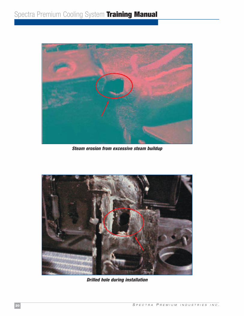
Steam erosion from excessive steam buildup
Drilled hole during installation
S P E C T R A P R E M I U M I N D U S T R I E S I N C . 21
Spectra Premium Cooling System Training Manual
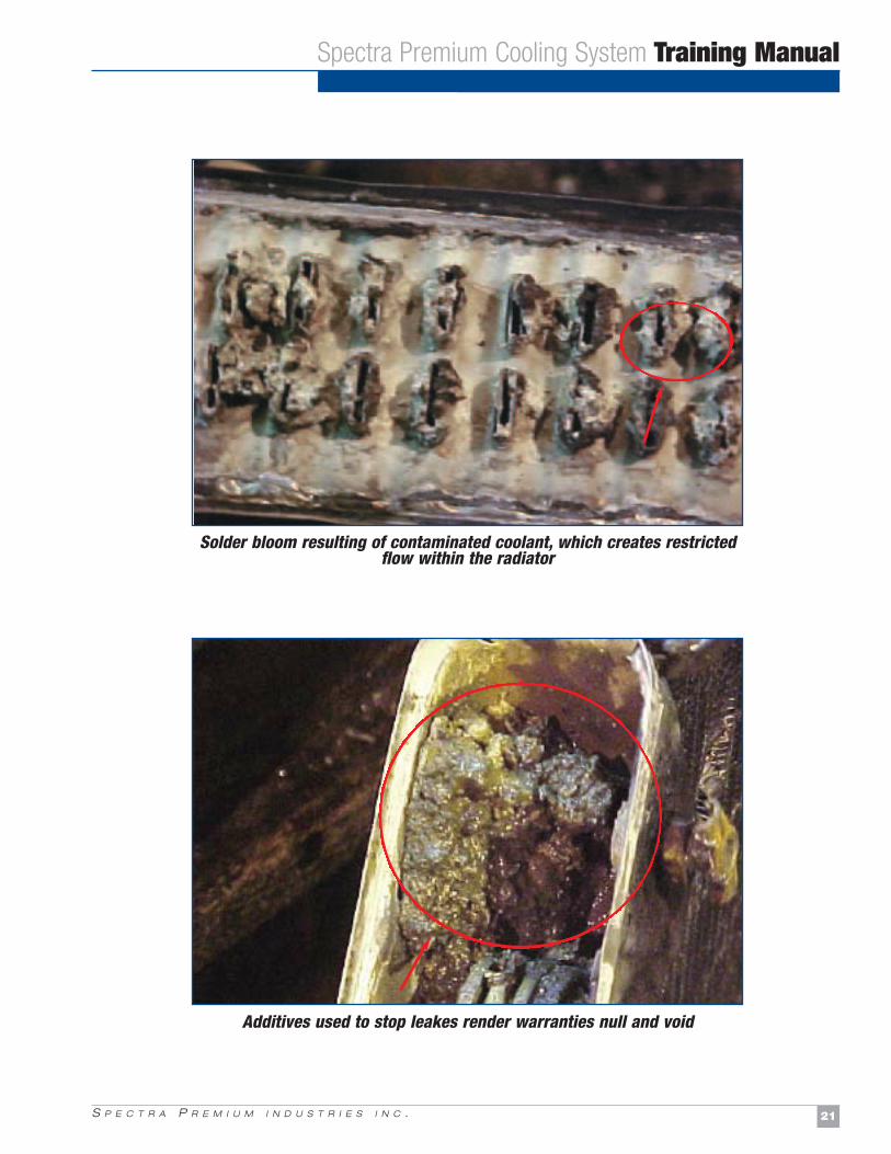
Solder bloom resulting of contaminated coolant, which creates restrictedflow within the radiator
Additives used to stop leakes render warranties null and void
S P E C T R A P R E M I U M I N D U S T R I E S I N C .22
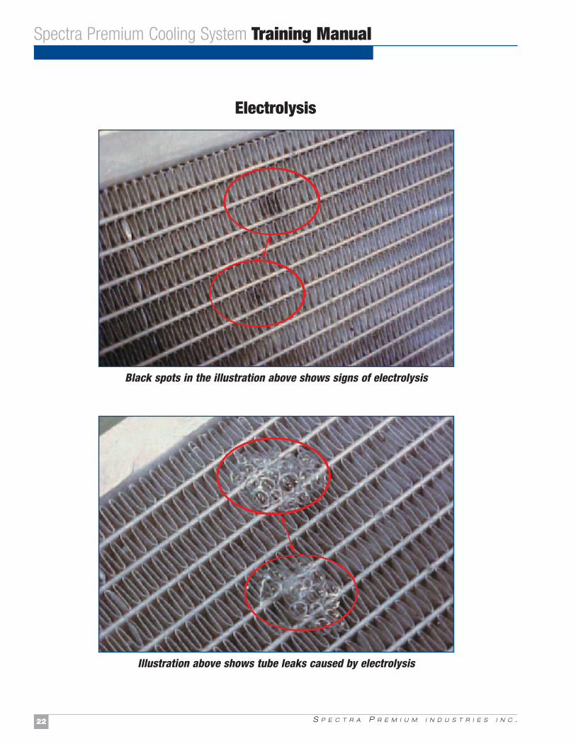
Electrolysis
Spectra Premium Cooling System Training Manual
Black spots in the illustration above shows signs of electrolysis
Illustration above shows tube leaks caused by electrolysis
S P E C T R A P R E M I U M I N D U S T R I E S I N C . 23
Spectra Premium Cooling System Training Manual
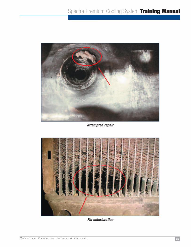
Attempted repair
Fin deterioration
S P E C T R A P R E M I U M I N D U S T R I E S I N C .24
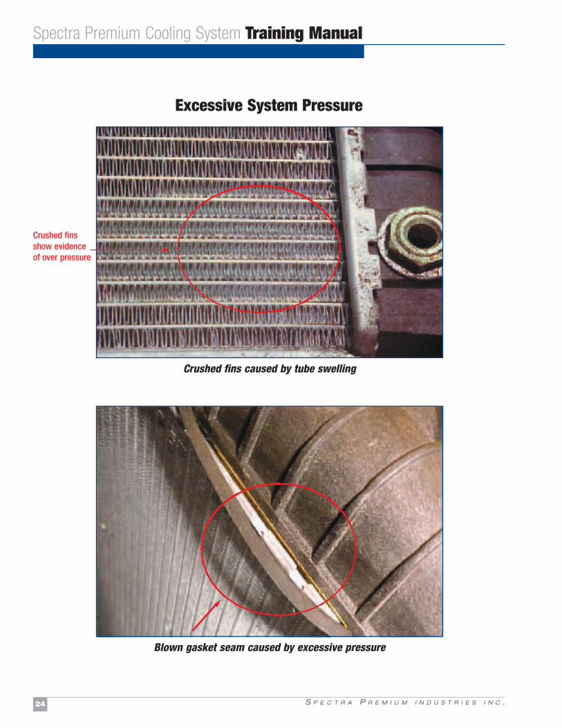
Excessive System Pressure
Spectra Premium Cooling System Training Manual
Crushed fins caused by tube swelling
Blown gasket seam caused by excessive pressure
Crushed finsshow evidenceof over pressure
S P E C T R A P R E M I U M I N D U S T R I E S I N C . 25
Spectra Premium Cooling System Training Manual
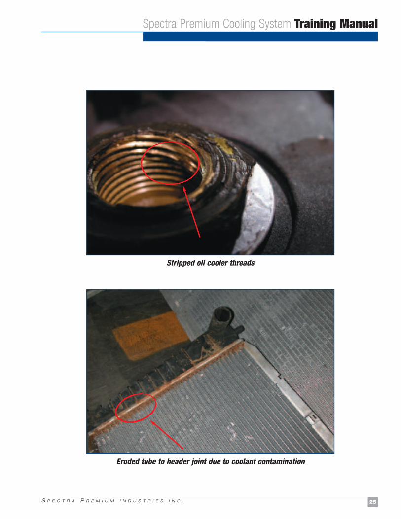
Stripped oil cooler threads
Eroded tube to header joint due to coolant contamination
S P E C T R A P R E M I U M I N D U S T R I E S I N C .26
Spectra Premium Cooling System Training Manual
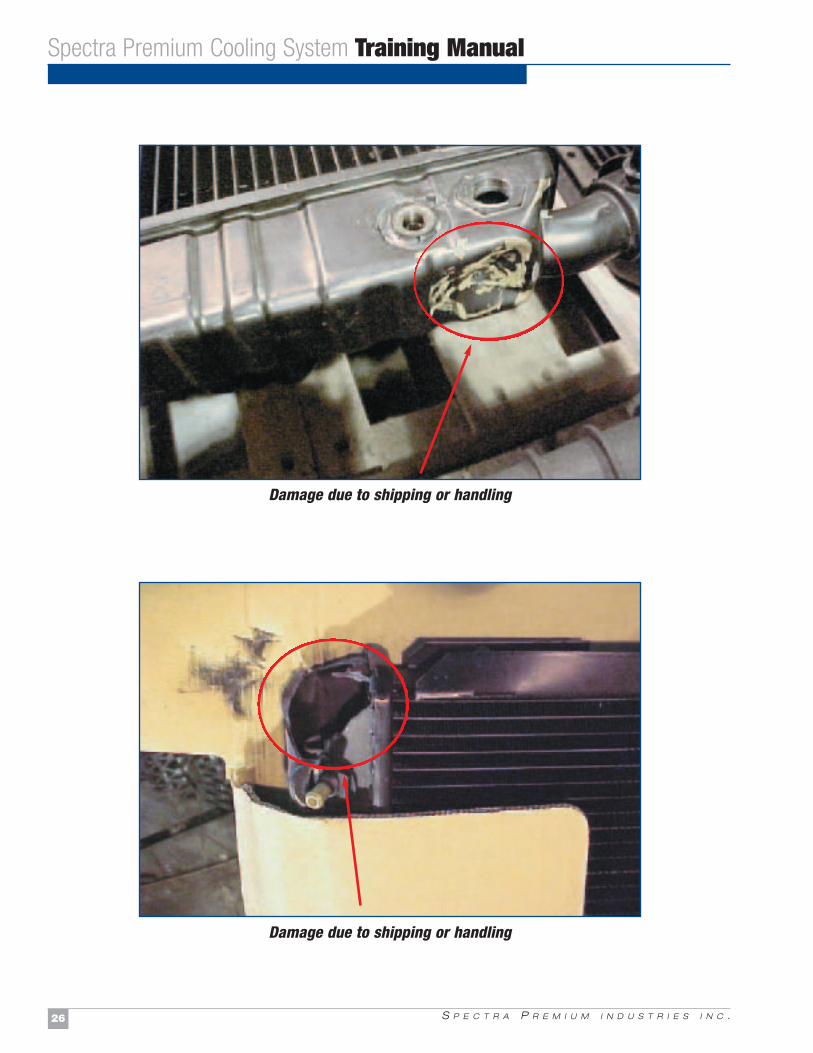
Damage due to shipping or handling
Damage due to shipping or handling
A R E T H E O N L Y C H O I C EWHY SPECTRA PREMIUM
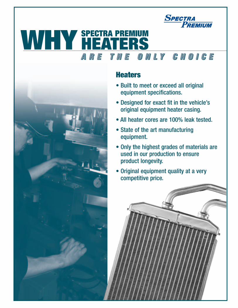
HEATERSA R E T H E O N L Y C H O I C E
Heaters• Built to meet or exceed all original
equipment specifications.
• Designed for exact fit in the vehicle’soriginal equipment heater casing.
• All heater cores are 100% leak tested.
• State of the art manufacturingequipment.
• Only the highest grades of materials areused in our production to ensureproduct longevity.
• Original equipment quality at a very competitive price.

S P E C T R A P R E M I U M I N D U S T R I E S I N C . 29
2.0 Heater Cores
2.1 FunctionHeater cores are like miniature radiators. They are located inside the dash of the vehicle next to the A/C evaporator. Their function is tosupply heat to the passenger compartment, using heat created by the engine. Hot coolant flows through the heater core to provideenough heat to warm the passenger compartment. It uses a blower motor that pushes the heat into the vehicles ventilation system.
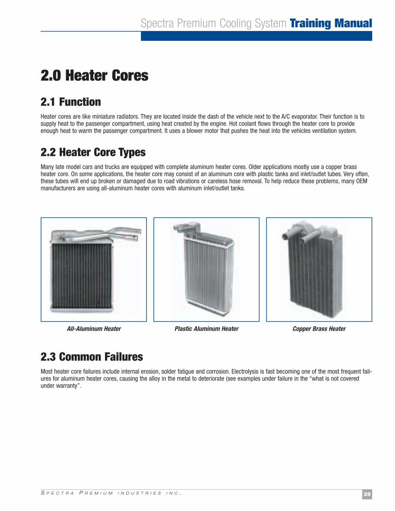
2.2 Heater Core TypesMany late model cars and trucks are equipped with complete aluminum heater cores. Older applications mostly use a copper brassheater core. On some applications, the heater core may consist of an aluminum core with plastic tanks and inlet/outlet tubes. Very often,these tubes will end up broken or damaged due to road vibrations or careless hose removal. To help reduce these problems, many OEMmanufacturers are using all-aluminum heater cores with aluminum inlet/outlet tanks.
2.3 Common Failures Most heater core failures include internal erosion, solder fatigue and corrosion. Electrolysis is fast becoming one of the most frequent fail-ures for aluminum heater cores, causing the alloy in the metal to deteriorate (see examples under failure in the “what is not coveredunder warranty”.
Spectra Premium Cooling System Training Manual
All-Aluminum Heater Plastic Aluminum Heater Copper Brass Heater
S P E C T R A P R E M I U M I N D U S T R I E S I N C .30
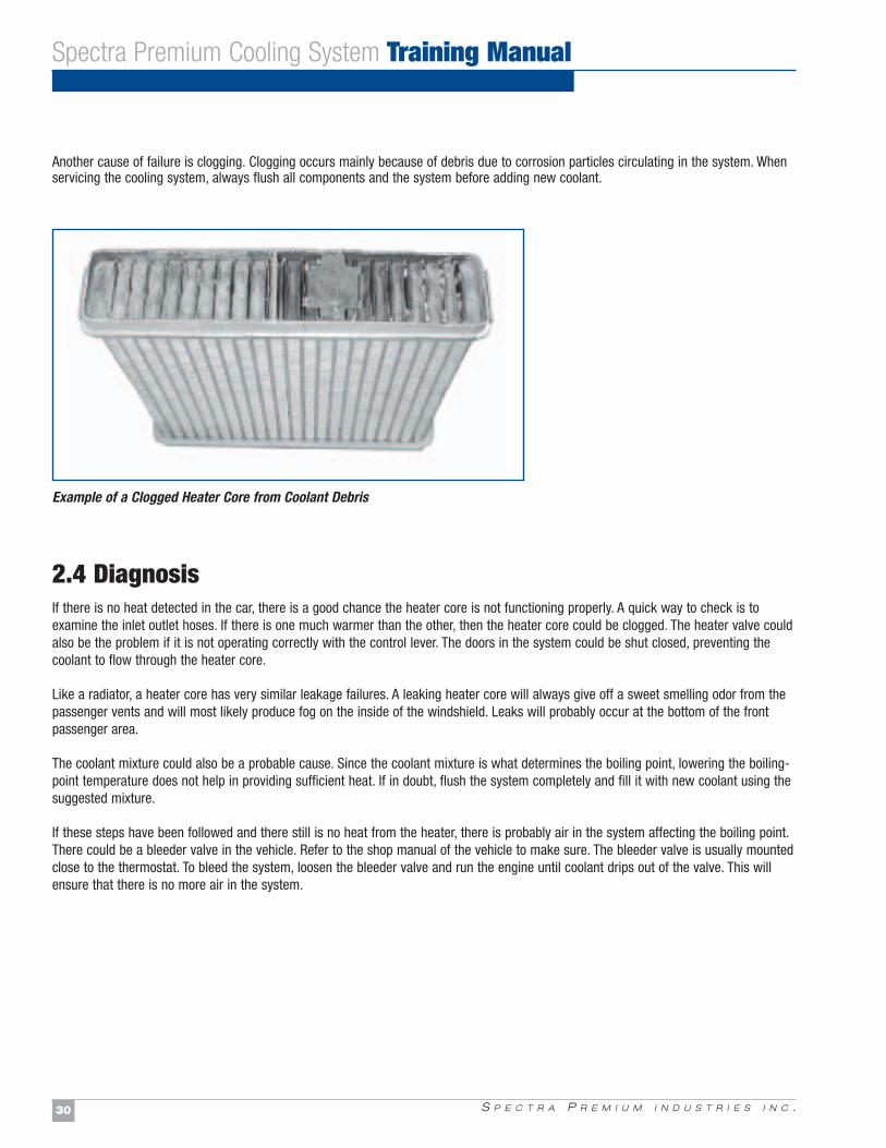
Another cause of failure is clogging. Clogging occurs mainly because of debris due to corrosion particles circulating in the system. Whenservicing the cooling system, always flush all components and the system before adding new coolant.
2.4 DiagnosisIf there is no heat detected in the car, there is a good chance the heater core is not functioning properly. A quick way to check is toexamine the inlet outlet hoses. If there is one much warmer than the other, then the heater core could be clogged. The heater valve couldalso be the problem if it is not operating correctly with the control lever. The doors in the system could be shut closed, preventing thecoolant to flow through the heater core.
Like a radiator, a heater core has very similar leakage failures. A leaking heater core will always give off a sweet smelling odor from thepassenger vents and will most likely produce fog on the inside of the windshield. Leaks will probably occur at the bottom of the frontpassenger area.
The coolant mixture could also be a probable cause. Since the coolant mixture is what determines the boiling point, lowering the boiling-point temperature does not help in providing sufficient heat. If in doubt, flush the system completely and fill it with new coolant using thesuggested mixture.
If these steps have been followed and there still is no heat from the heater, there is probably air in the system affecting the boiling point.There could be a bleeder valve in the vehicle. Refer to the shop manual of the vehicle to make sure. The bleeder valve is usually mountedclose to the thermostat. To bleed the system, loosen the bleeder valve and run the engine until coolant drips out of the valve. This willensure that there is no more air in the system.
Spectra Premium Cooling System Training Manual
Example of a Clogged Heater Core from Coolant Debris
A R E T H E O N L Y C H O I C EWHY SPECTRA PREMIUM
CONDENSERSA R E T H E O N L Y C H O I C E
A/C Condensers
• Built to meet or exceed all originalequipment cooling specifications.
• All models are supplied in the sameconstruction style of the Originalequipment manufacturer.
• QS9000/ISO9001 manufacturers supplyall A/C Condensers.
• Drop in fit for easy installation.
• Original equipment quality at a very competitive price.

S P E C T R A P R E M I U M I N D U S T R I E S I N C . 33
Condensers
3.1 FunctionThe function of a condenser is exactly the same as that of a radiator. For instance, it has tubes and fins to release heat. The radiator usesits tubes and fins to absorb heat from the engine coolant, the condenser does the same except it absorbs heat from the A/C refrigerant.
A condenser is always installed in between the radiator and the front grill. It needs as much airflow as possible to go through the fins andcool properly. If the condenser is not cooled sufficiently, it will not be able to change the refrigerant back from gas to liquid, which is thestate needed for cool air.
As its name suggests, a condenser will condense the refrigerant that circulates through it. At this point, this is where the refrigerant mustrelease its heat.
Heat is released from the condenser in many ways. First, when the A/C system is engaged, an electric or engine-driven coolant fan pullsfresh air through the condenser. Secondly, the front of the grill enables the outside ambiant air to flow through the condenser. Some moreaerodynamic vehicles have no front grill to let the fresh air from the outside in. These vehicles use special air deflectors located under thefront body to direct the air flow when the fan is running or when the vehicle is in motion.
Lastly, the majority of today's vehicles have deflectors in between the condenser and the front grill to concentrate the flow of fresh air tothe condenser
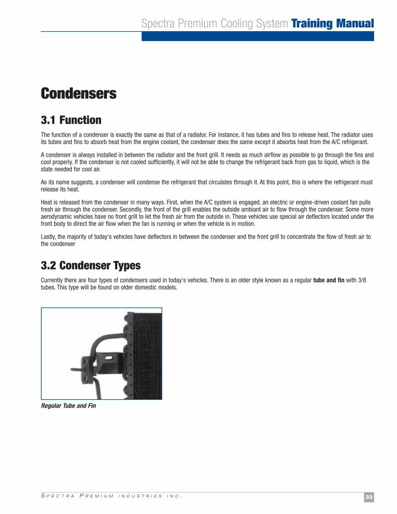
3.2 Condenser TypesCurrently there are four types of condensers used in today's vehicles. There is an older style known as a regular tube and fin with 3/8tubes. This type will be found on older domestic models.
Spectra Premium Cooling System Training Manual
Regular Tube and Fin
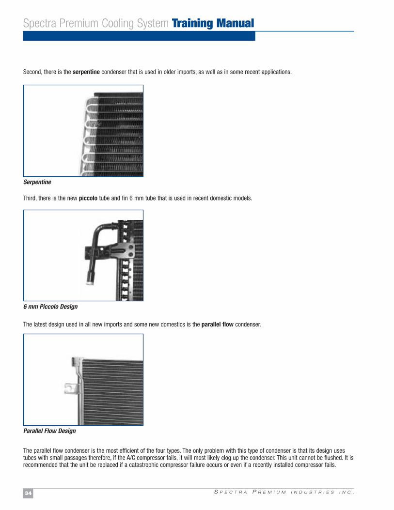
Second, there is the serpentine condenser that is used in older imports, as well as in some recent applications.
Third, there is the new piccolo tube and fin 6 mm tube that is used in recent domestic models.
The latest design used in all new imports and some new domestics is the parallel flow condenser.
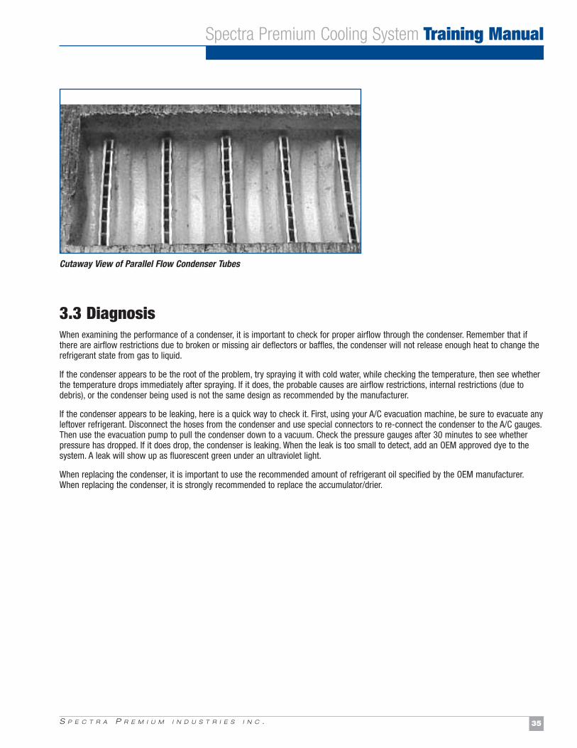
The parallel flow condenser is the most efficient of the four types. The only problem with this type of condenser is that its design usestubes with small passages therefore, if the A/C compressor fails, it will most likely clog up the condenser. This unit cannot be flushed. It isrecommended that the unit be replaced if a catastrophic compressor failure occurs or even if a recently installed compressor fails.
S P E C T R A P R E M I U M I N D U S T R I E S I N C .34
Spectra Premium Cooling System Training Manual
Serpentine
6 mm Piccolo Design
Parallel Flow Design
S P E C T R A P R E M I U M I N D U S T R I E S I N C . 35
Spectra Premium Cooling System Training Manual
3.3 DiagnosisWhen examining the performance of a condenser, it is important to check for proper airflow through the condenser. Remember that ifthere are airflow restrictions due to broken or missing air deflectors or baffles, the condenser will not release enough heat to change therefrigerant state from gas to liquid.
If the condenser appears to be the root of the problem, try spraying it with cold water, while checking the temperature, then see whetherthe temperature drops immediately after spraying. If it does, the probable causes are airflow restrictions, internal restrictions (due todebris), or the condenser being used is not the same design as recommended by the manufacturer.
If the condenser appears to be leaking, here is a quick way to check it. First, using your A/C evacuation machine, be sure to evacuate anyleftover refrigerant. Disconnect the hoses from the condenser and use special connectors to re-connect the condenser to the A/C gauges.Then use the evacuation pump to pull the condenser down to a vacuum. Check the pressure gauges after 30 minutes to see whetherpressure has dropped. If it does drop, the condenser is leaking. When the leak is too small to detect, add an OEM approved dye to thesystem. A leak will show up as fluorescent green under an ultraviolet light.
When replacing the condenser, it is important to use the recommended amount of refrigerant oil specified by the OEM manufacturer.When replacing the condenser, it is strongly recommended to replace the accumulator/drier.
Cutaway View of Parallel Flow Condenser Tubes