Embed Size (px)
Citation preview
Springback Characteristics of Magnesium Alloy Sheet AZ31B
in Draw-Bending
Takayuki Hama, Yuhta Kariyazaki*, Keisuke Ochi*, Hitoshi Fujimoto and Hirohiko Takuda
Department of Energy Science and Technology, Kyoto University, Kyoto 606-8501, Japan
In this study, we carried out a two-dimensional draw-bending test on an AZ31B magnesium alloy sheet at various forming temperaturesand blank holding forces, and the springback characteristics of the Mg alloy sheet were systematically examined. The amount of springbackdecreased with increasing temperature and blank holding force. The decrease in the amount of springback caused by the increase in temperaturewas much larger than that caused by the increase in blank holding force, which indicated that increasing temperature was much more effectivefor decreasing the amount of springback than increasing blank holding force. The amount of springback became negligible at 200�C and above.This result was attributable to the following factors: (a) flow stress decreased rapidly as temperature increased, (b) reverse bending on thesidewall arose at 150�C and above, and (c) fine grains due to dynamic recrystallization were formed at 200�C and above. Microstructureevolution during the draw-bending test was also observed with particular focus on twinning, and its effects on springback characteristics werestudied in detail. [doi:10.2320/matertrans.P-M2010803]
(Received August 31, 2009; Accepted January 18, 2010; Published March 25, 2010)
Keywords: magnesium alloy sheet AZ31B, springback, sheet metal forming, warm forming, reverse bending, twinning, recrystallization
1. Introduction
Magnesium (hereafter Mg) alloys are the lightest materialsused for structural components owing to their high specificstrength and stiffness.1,2) Besides, Mg alloys also haveadvantages in terms of functional properties, such asrecyclability1–3) and high electromagnetic shielding.1–4) Be-cause of increasing demand for lightweight materials forautomobile and electrical devices,1,2) Mg alloys have recentlybeen attracting much attention. Mg alloys are now applied invarious components, such as the housing of laptop computersand cellular phones, and automobile body structures.
Conventionally, the above components using Mg alloysare mainly manufactured by die casting and thixoform-ing.1,4–6) The press forming of Mg alloy sheets has recentlyattracted attention because the application of press formingcan further expand the use of Mg alloys. However, there arevery few applications of press forming because Mg alloysheets have poor formability at room temperature (RT)mainly owing to the limited number of slip systems inhexagonal close-packed (hereafter HCP) Mg alloys. Becausethe critical shear stress of non basal slip systems markedlydecreases with an increase in forming temperature, warmforming is one of the effective methods of improvingformability. Recently, warm forming has received muchinterest and many studies have been carried out particularlyon warm deep-drawing processes.5–10)
Springback is one of the most critical defects in sheetmetal forming, and a considerable amount of time is neededto compensate for this defect. For conventional structuralsheet metals such as steel and aluminum, springbackcharacteristics have been extensively studied both exper-imentally and numerically (e.g., Refs. 11–14)). On the otherhand, research studies on the springback of Mg alloy sheetsare few. Chen and Huang,15) Paisarn et al.,16) and Bruniet al.17) carried out experiments on air bending processes of
Mg alloy sheets and investigated the effects of temperatureon springback. Kim et al.4) and Matsui et al.18) conductedexperiments on two-dimensional draw-bending processesand studied the effects of temperature on springback.They reported that the amount of springback decreases withincreasing temperature and vanishes at about 300�C. Theyexplained that this is attributable to the decrease in flowstress with increasing temperature. Although the decreasein flow stress is apparently an important factor, this alonecannot explain why springback vanishes at 300�C. Further-more, Young’s modulus, one of the important factorsdetermining the amount of springback, may also changewith temperature. Kim et al. have examined the effectof blank holding force (BHF) on springback.4) However,considerable research is still required to understand theeffect of BHF in detail. In draw-bending, reverse bendingmay sometimes arise on the sidewall depending on theforming conditions, reducing the amount of springback.14,19)
Indeed, even springforward may arise when reverse bendingtakes place. Therefore, it is crucial to examine theoccurrence of reverse bending during draw-bending, whichhas not been studied until now.
It is also necesssary to determine the effect of micro-structure evolution during deformation on springback be-cause both twinning and recrystallization affect the defor-mation of Mg alloy sheets. Twinning plays a significant rolein the inflection of the stress-strain curve when Mg alloysheets are subjected to in-plane compression at RT .20) This isbecause a strong basal texture with most of the c-axes alignedin the sheet normal direction is initially formed in rolledMg alloy sheets.21,22) Recently, it has been reported thatin-plane tension after compressive deformation at RT isinitially dominated by the disappearance of twins, yieldingan inflected stress-strain curve similar to that observed inin-plane compression.21) Similar deformation characteristicshave also been observed in extruded Mg alloys.23,24) Intypical draw-bending, a sheet undergoes bending at the dieshoulder, followed by unbending on the sidewall; thus,*Graduate Student, Kyoto University
Materials Transactions, Vol. 51, No. 4 (2010) pp. 685 to 693#2010 The Japan Society for Technology of Plasticity
sheet surfaces undergo tension and compression during theprocess. Therefore, similar microstructure evolution shouldtake place on the surfaces of sheet. However, no suchmicrostructure observations during draw-bending tests havebeen reported yet.
In this study, we carried out a two-dimensional draw-bending test on an AZ31B Mg alloy sheet at varioustemperatures and BHF. Both macroscopic investigations,including the measurement of sidewall opening and theobservations of reverse bending at a sidewall, and micro-scopic investigations of microstructure evolution were con-ducted, and the springback characteristics of the Mg alloysheet were systematically studied in detail.
2. Tensile Properties of Material
2.1 Experimental proceduresA commercial Mg alloy sheet of AZ31B with a 0.8mm
thickness produced by Osaka Fuji Corporation was used.The material was annealed at 350�C for 1.5 h to obtain an Otemper before the experiment. A uniaxial tensile test wascarried out at various temperatures to determine the tensileproperties of the Mg alloy sheet. JIS13B tensile specimenswere machined parallel to the rolling direction. The experi-ment was carried out at 25 (RT), 75, 100, 150, 200, and225�C. The experiment at elevated temperatures was carriedout in a furnace, in which the internal atmosphere was heatedwith a heater and controlled to within �5�C of the presettemperature during the experiment. A strain gauge (KyowaElectronic Instruments Co., KFH-5-120-C1-23) was used toprecisely measure the small initial strains and Young’smodulus. On the other hand, the total strain to fracture atelevated temperatures was measured by image analysis usinga video camcorder placed outside the furnace, whereas thatat RT was measured using an extensometer. In both cases, thegage length was 50mm. Each tensile test was carried out atan initial strain rate of 0.003 s�1.
2.2 Tensile propertiesThe nominal stress-nominal strain curves obtained are
shown in Fig. 1. The fracture strain is about 20% at RT andincreases with temperature. At 200�C and above, the fracturestrain is about 60%, consistent with results in the literature.25)
On the other hand, the nominal strain at the tensile strength isabout 15% regardless of the temperature in this study. Thisresult indicates that fracture strain increases with temperaturemainly because of the enhancement of local elongation.
Figure 2 illustrates the relationships of temperature withtensile strength and 0.2% proof stress. Both tensile strengthand 0.2% proof stress decrease almost linearly with in-creasing temperature. The tensile strength at 225�C is almosthalf as large as that at RT . Figure 3 shows the relationshipbetween temperature and Young’s modulus. Young’s mod-ulus is almost constant from RT to 100�C, but it decreaseswhen the temperature exceeds 100�C. Young’s moduli atRT and 225�C are about 42 and 27GPa, respectively. Theseresults are qualitatively in agreement with those in theliterature.26)
Generally, decreases in tensile strength and 0.2% proofstress, i.e., flow stress, yield a smaller amount of springback,
whereas a decrease in Young’s modulus yields a largeramount of springback. Therefore, from the viewpoint oftensile properties, the change in the amount of springbackwith increasing temperature is determined from the relation-ship between flow stress and Young’s modulus.
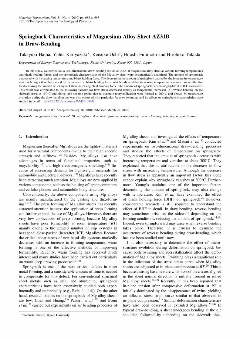
Figure 4 shows the nominal stress-nominal strain curvesat RT , 150�C, and 200�C in which the specimen wasunloaded and reloaded during the test. The result for amild steel sheet is also shown in Fig. 4(a) for reference.
Tensile strength300
RT
200 100°Cσ/M
Pa
150°C
100200°C
00
225°CNom
inal
str
ess,
0 0.2 0.4 0.6Nominal strain, ε
Fig. 1 Nominal stress-nominal strain curves at various temperatures.
300
0.2% proof stress
Tensile strength
/MPa
200σ
T/M
Paσ
0.2
100
00 50 100 150 200 250T
ensi
le s
tren
gth,
0.2%
pro
of s
tres
s,
Temperature, T /°C
Fig. 2 Relationships of temperature with tensile strength and 0.2% proof
stress.
50
40
30
20
10
You
ng’s
mod
ulus
, E /G
Pa
0 50 100 150 200 2500
Temperature, T /°C
Fig. 3 Relationship between temperature and Young’s modulus.
686 T. Hama, Y. Kariyazaki, K. Ochi, H. Fujimoto and H. Takuda
Compared with the mild steel sheet, the Mg alloy sheetexhibits significant strain hysteresis during unloading andreloading. This has also been reported in the literature.27–29)
Caceres et al. have shown that the hysteresis loopsprogressively developed up to a plastic strain of about 1–2%.27) As shown in Figs. 4(b) and 4(c), strain hysteresis isobserved irrespective of temperature. Because strain hys-teresis clearly yields a large amount of springback, theseresults show that its effect on springback characteristicsshould be studied at various temperatures. This will be partof our future work.
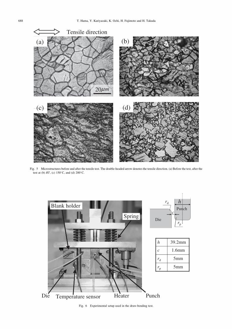
2.3 MicrostructuresMicrostructures before and after the tensile test are shown
in Fig. 5. Sheet surfaces near fracture regions were observedfor specimens after the test. The initial average graindiameter30) is about 20 mm. The grains are equiaxial, andtwins are rarely observed before the test (Fig. 5(a)). At RT ,the grain size remains the same and a small number of twinsare observed (Fig. 5(b)). At 150�C, most grains elongatealong the tensile direction and fine grains start to form nearthe grain boundaries (Fig. 5(c)). These fine grains may beattributed to dynamic recrystallization. They are dominantover the entire area of the specimen when the temperature is200�C and above (Fig. 5(d)). This result indicates that therecrystallization as well as the activation of nonbasal slipsystems31) is one of the factors causing the changes in thetensile properties at elevated temperatures shown in Figs. 2and 3.
3. Two-Dimensional Draw-Bending Test
3.1 Experimental proceduresFigure 6 shows the experimental setup developed for the
two-dimensional draw-bending test. The die and punchshoulder radii, rd and rp, respectively, were 5mm, and theclearance between the punch and the die, c, was 1.6mm. Thedimensions of the sheet blank were 220mm long, 50mmwide, and 0.8mm thick. The longitudinal direction of thesheet was parallel to the rolling direction. Lubrication oil (G-2576, Nihon Kohsakuyu Co.) was used at all temperatures.BHF was supplied by four springs with a spring constant of235.7N/mm and was set by screw nuts. BHFs of 0, 0.49,0.98, 1.96, and 4.90 kN were applied. Note that the aboveBHFs do not include the empty weight of the blank holder,which is about 0.17 kN.
The tools were heated using heaters inserted into the tools,and their temperatures were controlled to preset values usingtemperature controllers. Temperatures of 25 (RT), 75, 100,150, 200, and 225�C were used. Insulator plates (MiorekHR-1(PMX-561), Ryoden Kasei Co.) were intercalatedbetween the die and the lower base plate and between theblank holder and the upper base plate to avoid heat transferfrom the tools to the base plates. Preliminary experimentsshowed that the temperature distributions on the sheet couldbe considered sufficiently uniform with a maximum error of7.5% from the preset temperatures.
The sheet was drawn with a constant punch speed of10mm/min up to a punch stroke of 50mm. At this punch
100(b)
200(a) Mild steel
/MPa
50100
Mg alloy
/MPa
σσ
0 Nom
inal
str
ess,
Nom
inal
str
ess,
1
E
0 0.002 0.004 0.006 0.008 0.0100 0.002 0.004 0.006 0.008 0.01
0
Nominal strain, εNominal strain, ε
(c)
80
100
/MPa
60
σ
20
40
Nom
inal
str
ess,
0 0.002 0.004 0.006 0.008Nominal strain, ε
Fig. 4 Hysteresis during unloading at various temperatures. E denotes Young’s modulus at the beginning of the test at RT . (a) RT ,
(b) 150�C, and (c) 200�C.
Springback Characteristics of Magnesium Alloy Sheet AZ31B in Draw-Bending 687
Tensile direction
(a) (b)
20 mµ
(c) (d)
Fig. 5 Microstructures before and after the tensile test. The double-headed arrow denotes the tensile direction. (a) Before the test, after the
test at (b) RT , (c) 150�C, and (d) 200�C.
Die
rd
Spring
Blank holderc
Punch
rp
h 39.2mm
c 1.6mm
rd 5mm
rp 5mm
Die PunchTemperature sensor Heater
h
Fig. 6 Experimental setup used in the draw-bending test.
688 T. Hama, Y. Kariyazaki, K. Ochi, H. Fujimoto and H. Takuda
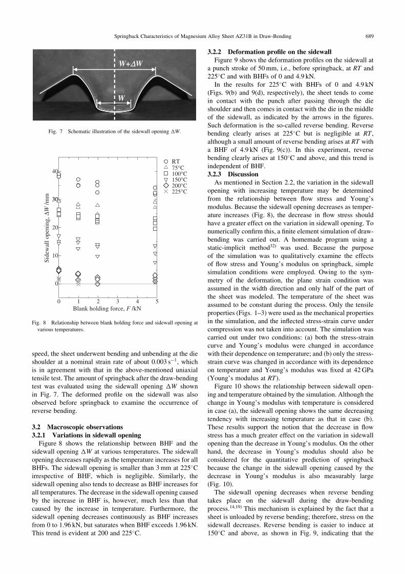
speed, the sheet underwent bending and unbending at the dieshoulder at a nominal strain rate of about 0.003 s�1, whichis in agreement with that in the above-mentioned uniaxialtensile test. The amount of springback after the draw-bendingtest was evaluated using the sidewall opening �W shownin Fig. 7. The deformed profile on the sidewall was alsoobserved before springback to examine the occurrence ofreverse bending.
3.2 Macroscopic observations3.2.1 Variations in sidewall opening
Figure 8 shows the relationship between BHF and thesidewall opening �W at various temperatures. The sidewallopening decreases rapidly as the temperature increases for allBHFs. The sidewall opening is smaller than 3mm at 225�Cirrespective of BHF, which is negligible. Similarly, thesidewall opening also tends to decrease as BHF increases forall temperatures. The decrease in the sidewall opening causedby the increase in BHF is, however, much less than thatcaused by the increase in temperature. Furthermore, thesidewall opening decreases continuously as BHF increasesfrom 0 to 1.96 kN, but saturates when BHF exceeds 1.96 kN.This trend is evident at 200 and 225�C.
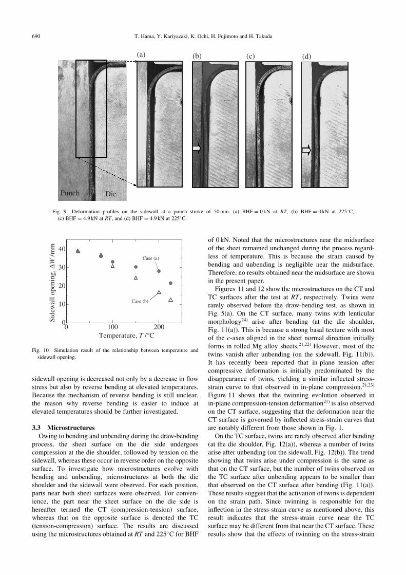
3.2.2 Deformation profile on the sidewallFigure 9 shows the deformation profiles on the sidewall at
a punch stroke of 50mm, i.e., before springback, at RT and225�C and with BHFs of 0 and 4.9 kN.
In the results for 225�C with BHFs of 0 and 4.9 kN(Figs. 9(b) and 9(d), respectively), the sheet tends to comein contact with the punch after passing through the dieshoulder and then comes in contact with the die in the middleof the sidewall, as indicated by the arrows in the figures.Such deformation is the so-called reverse bending. Reversebending clearly arises at 225�C but is negligible at RT ,although a small amount of reverse bending arises at RT witha BHF of 4.9 kN (Fig. 9(c)). In this experiment, reversebending clearly arises at 150�C and above, and this trend isindependent of BHF.3.2.3 Discussion
As mentioned in Section 2.2, the variation in the sidewallopening with increasing temperature may be determinedfrom the relationship between flow stress and Young’smodulus. Because the sidewall opening decreases as temper-ature increases (Fig. 8), the decrease in flow stress shouldhave a greater effect on the variation in sidewall opening. Tonumerically confirm this, a finite element simulation of draw-bending was carried out. A homemade program using astatic-implicit method32) was used. Because the purposeof the simulation was to qualitatively examine the effectsof flow stress and Young’s modulus on springback, simplesimulation conditions were employed. Owing to the sym-metry of the deformation, the plane strain condition wasassumed in the width direction and only half of the part ofthe sheet was modeled. The temperature of the sheet wasassumed to be constant during the process. Only the tensileproperties (Figs. 1–3) were used as the mechanical propertiesin the simulation, and the inflected stress-strain curve undercompression was not taken into account. The simulation wascarried out under two conditions: (a) both the stress-straincurve and Young’s modulus were changed in accordancewith their dependence on temperature; and (b) only the stress-strain curve was changed in accordance with its dependenceon temperature and Young’s modulus was fixed at 42GPa(Young’s modulus at RT).
Figure 10 shows the relationship between sidewall open-ing and temperature obtained by the simulation. Although thechange in Young’s modulus with temperature is consideredin case (a), the sidewall opening shows the same decreasingtendency with increasing temperature as that in case (b).These results support the notion that the decrease in flowstress has a much greater effect on the variation in sidewallopening than the decrease in Young’s modulus. On the otherhand, the decrease in Young’s modulus should also beconsidered for the quantitative prediction of springbackbecause the change in the sidewall opening caused by thedecrease in Young’s modulus is also measurably large(Fig. 10).
The sidewall opening decreases when reverse bendingtakes place on the sidewall during the draw-bendingprocess.14,19) This mechanism is explained by the fact that asheet is unloaded by reverse bending; therefore, stress on thesidewall decreases. Reverse bending is easier to induce at150�C and above, as shown in Fig. 9, indicating that the
W+∆∆W
W
Fig. 7 Schematic illustration of the sidewall opening �W .
4075°C100°C
RT
30
150°C200°C225°C
30
∆W/m
m
20
10
Side
wal
l ope
ning
,
0
0 1 2 3 4 5Blank holding force, F /kN
Fig. 8 Relationship between blank holding force and sidewall opening at
various temperatures.
Springback Characteristics of Magnesium Alloy Sheet AZ31B in Draw-Bending 689
sidewall opening is decreased not only by a decrease in flowstress but also by reverse bending at elevated temperatures.Because the mechanism of reverse bending is still unclear,the reason why reverse bending is easier to induce atelevated temperatures should be further investigated.
3.3 MicrostructuresOwing to bending and unbending during the draw-bending
process, the sheet surface on the die side undergoescompression at the die shoulder, followed by tension on thesidewall, whereas these occur in reverse order on the oppositesurface. To investigate how microstructures evolve withbending and unbending, microstructures at both the dieshoulder and the sidewall were observed. For each position,parts near both sheet surfaces were observed. For conven-ience, the part near the sheet surface on the die side ishereafter termed the CT (compression-tension) surface,whereas that on the opposite surface is denoted the TC(tension-compression) surface. The results are discussedusing the microstructures obtained at RT and 225�C for BHF
of 0 kN. Noted that the microstructures near the midsurfaceof the sheet remained unchanged during the process regard-less of temperature. This is because the strain caused bybending and unbending is negligible near the midsurface.Therefore, no results obtained near the midsurface are shownin the present paper.
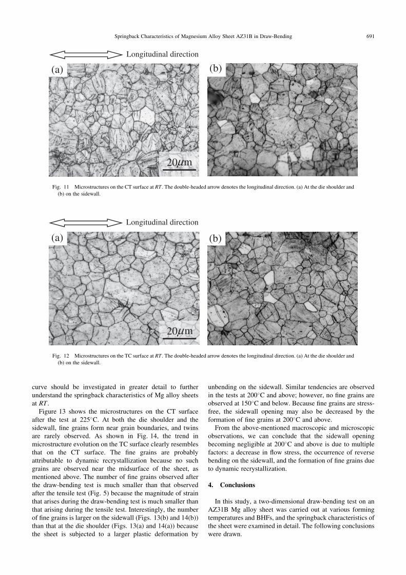
Figures 11 and 12 show the microstructures on the CT andTC surfaces after the test at RT , respectively. Twins wererarely observed before the draw-bending test, as shown inFig. 5(a). On the CT surface, many twins with lenticularmorphology24) arise after bending (at the die shoulder,Fig. 11(a)). This is because a strong basal texture with mostof the c-axes aligned in the sheet normal direction initiallyforms in rolled Mg alloy sheets.21,22) However, most of thetwins vanish after unbending (on the sidewall, Fig. 11(b)).It has recently been reported that in-plane tension aftercompressive deformation is initially predominated by thedisappearance of twins, yielding a similar inflected stress-strain curve to that observed in in-plane compression.21,23)
Figure 11 shows that the twinning evolution observed inin-plane compression-tension deformation21) is also observedon the CT surface, suggesting that the deformation near theCT surface is governed by inflected stress-strain curves thatare notably different from those shown in Fig. 1.
On the TC surface, twins are rarely observed after bending(at the die shoulder, Fig. 12(a)), whereas a number of twinsarise after unbending (on the sidewall, Fig. 12(b)). The trendshowing that twins arise under compression is the same asthat on the CT surface, but the number of twins observed onthe TC surface after unbending appears to be smaller thanthat observed on the CT surface after bending (Fig. 11(a)).These results suggest that the activation of twins is dependenton the strain path. Since twinning is responsible for theinflection in the stress-strain curve as mentioned above, thisresult indicates that the stress-strain curve near the TCsurface may be different from that near the CT surface. Theseresults show that the effects of twinning on the stress-strain
40
30Case (a)
∆W /m
m
20
10 Case (b)
0 100 2000Si
dew
all o
peni
ng,
Temperature, T /°C
Fig. 10 Simulation result of the relationship between temperature and
sidewall opening.
(a) (b) (c) (d)
DiePunch
Fig. 9 Deformation profiles on the sidewall at a punch stroke of 50mm. (a) BHF ¼ 0 kN at RT , (b) BHF ¼ 0 kN at 225�C,
(c) BHF ¼ 4:9 kN at RT , and (d) BHF ¼ 4:9 kN at 225�C.
690 T. Hama, Y. Kariyazaki, K. Ochi, H. Fujimoto and H. Takuda
curve should be investigated in greater detail to furtherunderstand the springback characteristics of Mg alloy sheetsat RT .
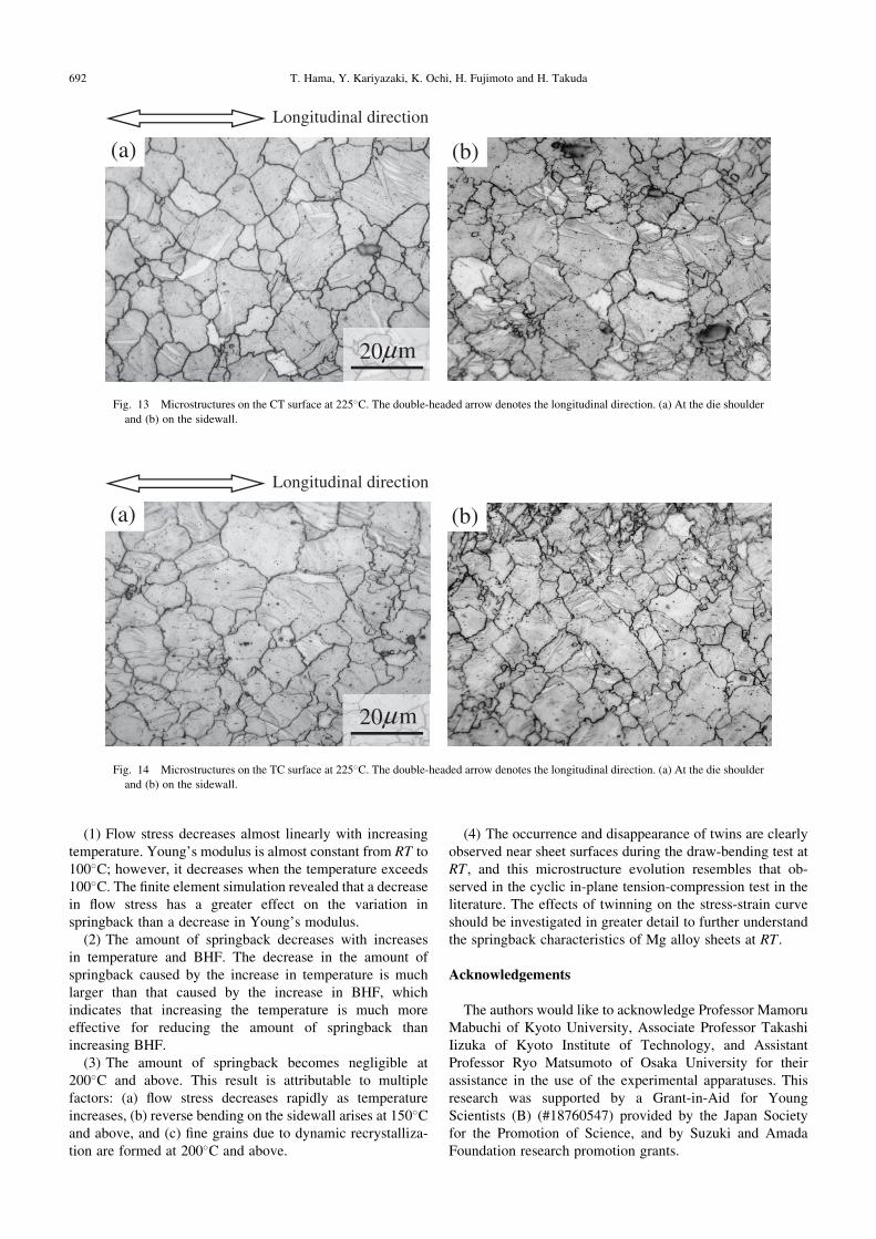
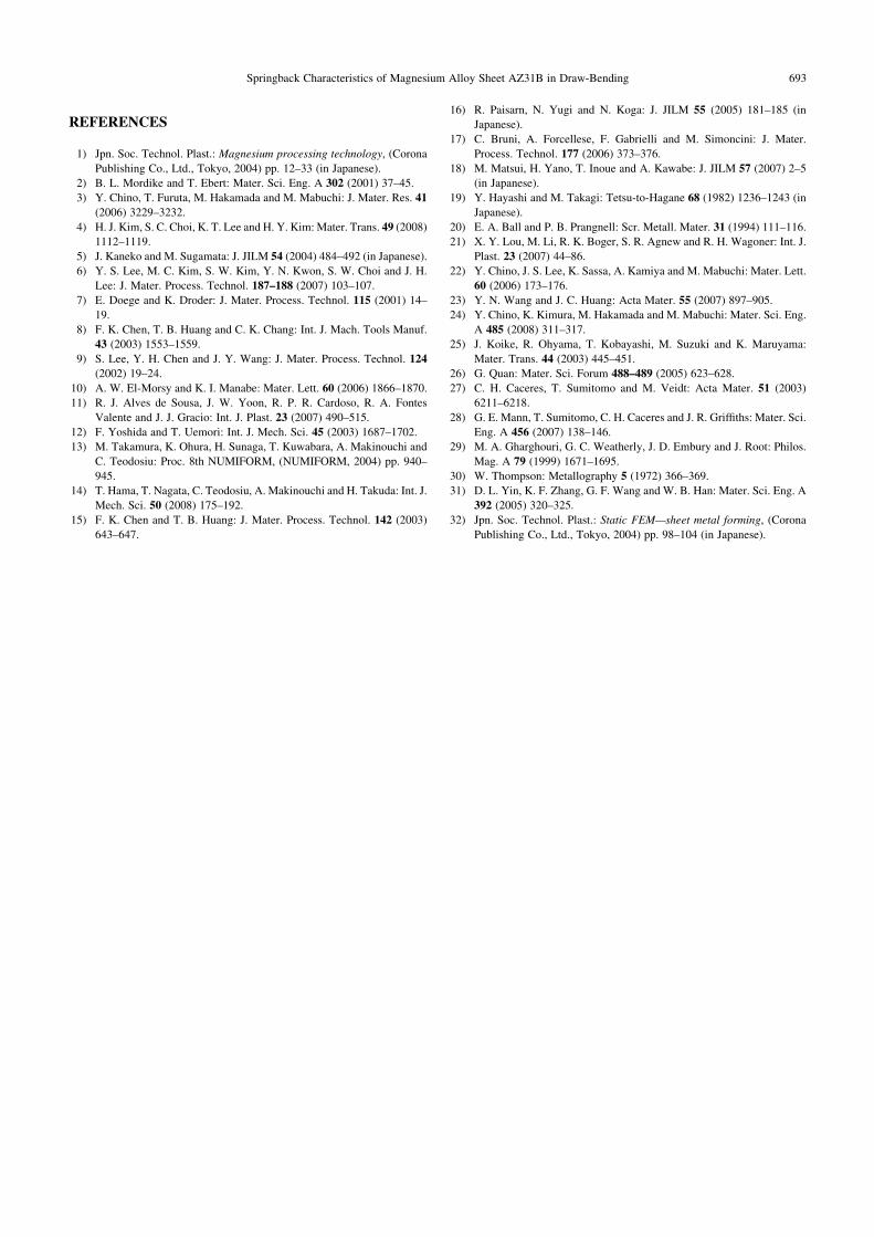
Figure 13 shows the microstructures on the CT surfaceafter the test at 225�C. At both the die shoulder and thesidewall, fine grains form near grain boundaries, and twinsare rarely observed. As shown in Fig. 14, the trend inmicrostructure evolution on the TC surface clearly resemblesthat on the CT surface. The fine grains are probablyattributable to dynamic recrystallization because no suchgrains are observed near the midsurface of the sheet, asmentioned above. The number of fine grains observed afterthe draw-bending test is much smaller than that observedafter the tensile test (Fig. 5) because the magnitude of strainthat arises during the draw-bending test is much smaller thanthat arising during the tensile test. Interestingly, the numberof fine grains is larger on the sidewall (Figs. 13(b) and 14(b))than that at the die shoulder (Figs. 13(a) and 14(a)) becausethe sheet is subjected to a larger plastic deformation by
unbending on the sidewall. Similar tendencies are observedin the tests at 200�C and above; however, no fine grains areobserved at 150�C and below. Because fine grains are stress-free, the sidewall opening may also be decreased by theformation of fine grains at 200�C and above.
From the above-mentioned macroscopic and microscopicobservations, we can conclude that the sidewall openingbecoming negligible at 200�C and above is due to multiplefactors: a decrease in flow stress, the occurrence of reversebending on the sidewall, and the formation of fine grains dueto dynamic recrystallization.
4. Conclusions
In this study, a two-dimensional draw-bending test on anAZ31B Mg alloy sheet was carried out at various formingtemperatures and BHFs, and the springback characteristics ofthe sheet were examined in detail. The following conclusionswere drawn.
Longitudinal direction
(a) (b)
20 mµ
Fig. 11 Microstructures on the CT surface at RT . The double-headed arrow denotes the longitudinal direction. (a) At the die shoulder and
(b) on the sidewall.
Longitudinal direction
(a) (b)
20 mµ
Fig. 12 Microstructures on the TC surface at RT . The double-headed arrow denotes the longitudinal direction. (a) At the die shoulder and
(b) on the sidewall.
Springback Characteristics of Magnesium Alloy Sheet AZ31B in Draw-Bending 691
(1) Flow stress decreases almost linearly with increasingtemperature. Young’s modulus is almost constant from RT to100�C; however, it decreases when the temperature exceeds100�C. The finite element simulation revealed that a decreasein flow stress has a greater effect on the variation inspringback than a decrease in Young’s modulus.
(2) The amount of springback decreases with increasesin temperature and BHF. The decrease in the amount ofspringback caused by the increase in temperature is muchlarger than that caused by the increase in BHF, whichindicates that increasing the temperature is much moreeffective for reducing the amount of springback thanincreasing BHF.
(3) The amount of springback becomes negligible at200�C and above. This result is attributable to multiplefactors: (a) flow stress decreases rapidly as temperatureincreases, (b) reverse bending on the sidewall arises at 150�Cand above, and (c) fine grains due to dynamic recrystalliza-tion are formed at 200�C and above.
(4) The occurrence and disappearance of twins are clearlyobserved near sheet surfaces during the draw-bending test atRT , and this microstructure evolution resembles that ob-served in the cyclic in-plane tension-compression test in theliterature. The effects of twinning on the stress-strain curveshould be investigated in greater detail to further understandthe springback characteristics of Mg alloy sheets at RT .
Acknowledgements
The authors would like to acknowledge Professor MamoruMabuchi of Kyoto University, Associate Professor TakashiIizuka of Kyoto Institute of Technology, and AssistantProfessor Ryo Matsumoto of Osaka University for theirassistance in the use of the experimental apparatuses. Thisresearch was supported by a Grant-in-Aid for YoungScientists (B) (#18760547) provided by the Japan Societyfor the Promotion of Science, and by Suzuki and AmadaFoundation research promotion grants.
Longitudinal direction
(a) (b)
20 mµ
Fig. 13 Microstructures on the CT surface at 225�C. The double-headed arrow denotes the longitudinal direction. (a) At the die shoulder
and (b) on the sidewall.
Longitudinal direction
(a) (b)
20 mµ
Fig. 14 Microstructures on the TC surface at 225�C. The double-headed arrow denotes the longitudinal direction. (a) At the die shoulder
and (b) on the sidewall.
692 T. Hama, Y. Kariyazaki, K. Ochi, H. Fujimoto and H. Takuda
REFERENCES
1) Jpn. Soc. Technol. Plast.: Magnesium processing technology, (Corona
Publishing Co., Ltd., Tokyo, 2004) pp. 12–33 (in Japanese).
2) B. L. Mordike and T. Ebert: Mater. Sci. Eng. A 302 (2001) 37–45.
3) Y. Chino, T. Furuta, M. Hakamada and M. Mabuchi: J. Mater. Res. 41
(2006) 3229–3232.
4) H. J. Kim, S. C. Choi, K. T. Lee and H. Y. Kim:Mater. Trans. 49 (2008)
1112–1119.
5) J. Kaneko and M. Sugamata: J. JILM 54 (2004) 484–492 (in Japanese).
6) Y. S. Lee, M. C. Kim, S. W. Kim, Y. N. Kwon, S. W. Choi and J. H.
Lee: J. Mater. Process. Technol. 187–188 (2007) 103–107.
7) E. Doege and K. Droder: J. Mater. Process. Technol. 115 (2001) 14–
19.
8) F. K. Chen, T. B. Huang and C. K. Chang: Int. J. Mach. Tools Manuf.
43 (2003) 1553–1559.
9) S. Lee, Y. H. Chen and J. Y. Wang: J. Mater. Process. Technol. 124
(2002) 19–24.
10) A. W. El-Morsy and K. I. Manabe: Mater. Lett. 60 (2006) 1866–1870.
11) R. J. Alves de Sousa, J. W. Yoon, R. P. R. Cardoso, R. A. Fontes
Valente and J. J. Gracio: Int. J. Plast. 23 (2007) 490–515.
12) F. Yoshida and T. Uemori: Int. J. Mech. Sci. 45 (2003) 1687–1702.
13) M. Takamura, K. Ohura, H. Sunaga, T. Kuwabara, A. Makinouchi and
C. Teodosiu: Proc. 8th NUMIFORM, (NUMIFORM, 2004) pp. 940–
945.
14) T. Hama, T. Nagata, C. Teodosiu, A. Makinouchi and H. Takuda: Int. J.
Mech. Sci. 50 (2008) 175–192.
15) F. K. Chen and T. B. Huang: J. Mater. Process. Technol. 142 (2003)
643–647.
16) R. Paisarn, N. Yugi and N. Koga: J. JILM 55 (2005) 181–185 (in
Japanese).
17) C. Bruni, A. Forcellese, F. Gabrielli and M. Simoncini: J. Mater.
Process. Technol. 177 (2006) 373–376.
18) M. Matsui, H. Yano, T. Inoue and A. Kawabe: J. JILM 57 (2007) 2–5
(in Japanese).
19) Y. Hayashi and M. Takagi: Tetsu-to-Hagane 68 (1982) 1236–1243 (in
Japanese).
20) E. A. Ball and P. B. Prangnell: Scr. Metall. Mater. 31 (1994) 111–116.
21) X. Y. Lou, M. Li, R. K. Boger, S. R. Agnew and R. H. Wagoner: Int. J.
Plast. 23 (2007) 44–86.
22) Y. Chino, J. S. Lee, K. Sassa, A. Kamiya and M. Mabuchi: Mater. Lett.
60 (2006) 173–176.
23) Y. N. Wang and J. C. Huang: Acta Mater. 55 (2007) 897–905.
24) Y. Chino, K. Kimura, M. Hakamada and M. Mabuchi: Mater. Sci. Eng.
A 485 (2008) 311–317.
25) J. Koike, R. Ohyama, T. Kobayashi, M. Suzuki and K. Maruyama:
Mater. Trans. 44 (2003) 445–451.
26) G. Quan: Mater. Sci. Forum 488–489 (2005) 623–628.
27) C. H. Caceres, T. Sumitomo and M. Veidt: Acta Mater. 51 (2003)
6211–6218.
28) G. E. Mann, T. Sumitomo, C. H. Caceres and J. R. Griffiths: Mater. Sci.
Eng. A 456 (2007) 138–146.
29) M. A. Gharghouri, G. C. Weatherly, J. D. Embury and J. Root: Philos.
Mag. A 79 (1999) 1671–1695.
30) W. Thompson: Metallography 5 (1972) 366–369.
31) D. L. Yin, K. F. Zhang, G. F. Wang and W. B. Han: Mater. Sci. Eng. A
392 (2005) 320–325.
32) Jpn. Soc. Technol. Plast.: Static FEM—sheet metal forming, (Corona
Publishing Co., Ltd., Tokyo, 2004) pp. 98–104 (in Japanese).
Springback Characteristics of Magnesium Alloy Sheet AZ31B in Draw-Bending 693