Embed Size (px)
Citation preview
Study of Cosmic RayProton and Helium at
small atmospheric depths byBESS spectrometer
Raghunathan SrivatsanNorfolk State University
10/6/2004 UCSC
BESS Collaboration• KEK
T.Kumazawa, Y. Makida, K.Matsumoto, J.Suzuki, K.Tanaka, A.Yamomoto,T.Yoshida, K.Yoshimura
• The Univ. of TokyoH.Fuke, S.Haino, K.Izumi, S.Matsuda, N.Matsui,H.Matsumoto, J.Nishimura, T.Sanuki, Y.Yamamoto
• Kobe Univ.K.Abe, A.Itasaki, M.Nozaki, Y.Shikaze, Y.Takasugi, K.Takeuchi, K.Tanizaki, K.Yamato
• ISAST.Yamagami
• NASA/Goddard Space Flight CenterT.Hams, J.W.Mitchell, A.A.Moiseev, J.F.Ormes, M.Sasaki, R.E.Streitmatter
• Univ. of MarylandM.H.Lee, Z.D.Myers, E.S.Seo
• Norfolk State UniversityM.Khandaker, C.W.Salgado, R. Srivatsan, D.Weygand
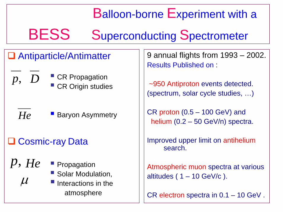
Balloon-borne Experiment with a
BESS Superconducting Spectrometer
Antiparticle/Antimatter
CR PropagationCR Origin studies
Baryon Asymmetry
Cosmic-ray Data
PropagationSolar Modulation,Interactions in the
atmosphere
9 annual flights from 1993 – 2002.Results Published on :
~950 Antiproton events detected.(spectrum, solar cycle studies, …)
CR proton (0.5 – 100 GeV) andhelium (0.2 – 50 GeV/n) spectra.
Improved upper limit on antiheliumsearch.
Atmospheric muon spectra at variousaltitudes ( 1 – 10 GeV/c ).
CR electron spectra in 0.1 – 10 GeV .
,p D
He
,p Heµ
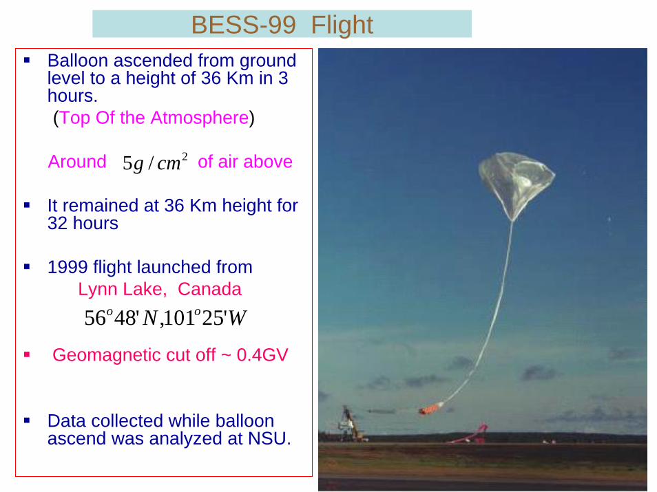
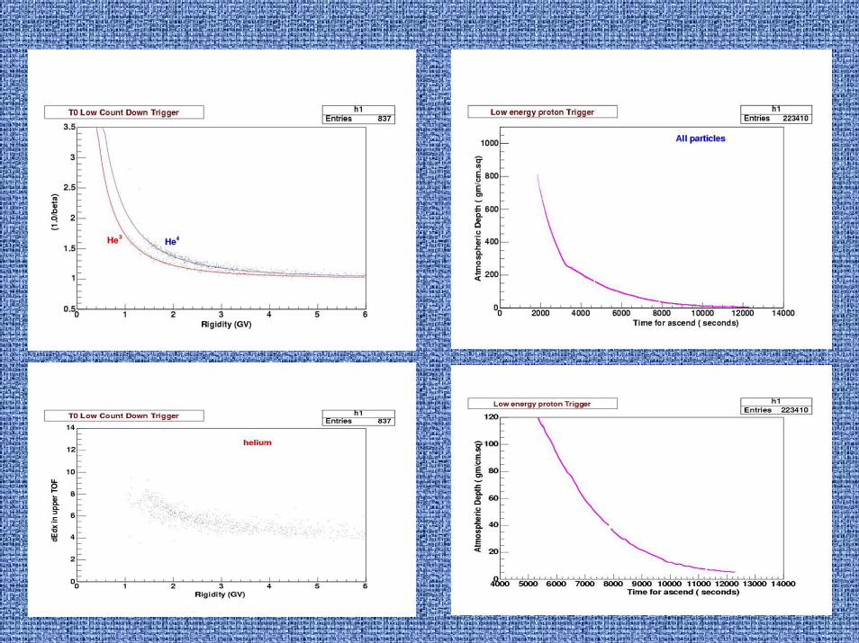
BESS-99 FlightBalloon ascended from ground level to a height of 36 Km in 3 hours.(Top Of the Atmosphere)
Around of air above
It remained at 36 Km height for 32 hours
1999 flight launched fromLynn Lake, Canada
Geomagnetic cut off ~ 0.4GV
Data collected while balloon ascend was analyzed at NSU.
WN oo '25101,'4856
2/5 cmg
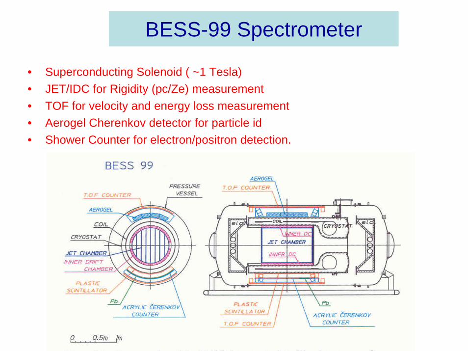
BESS-99 Spectrometer
• Superconducting Solenoid ( ~1 Tesla)• JET/IDC for Rigidity (pc/Ze) measurement• TOF for velocity and energy loss measurement• Aerogel Cherenkov detector for particle id• Shower Counter for electron/positron detection.
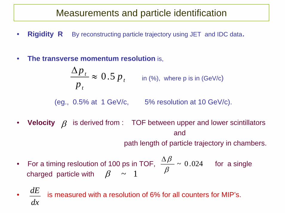
Measurements and particle identification
• Rigidity R By reconstructing particle trajectory using JET and IDC data.
• The transverse momentum resolution is,
in (%), where p is in (GeV/c)
(eg., 0.5% at 1 GeV/c, 5% resolution at 10 GeV/c).
• Velocity is derived from : TOF between upper and lower scintillatorsand
path length of particle trajectory in chambers.
• For a timing resloution of 100 ps in TOF, for a single charged particle with
• is measured with a resolution of 6% for all counters for MIP’s.
tt
t ppp 5.0≈
∆
β
024.0~ββ∆
1~β
dxdE
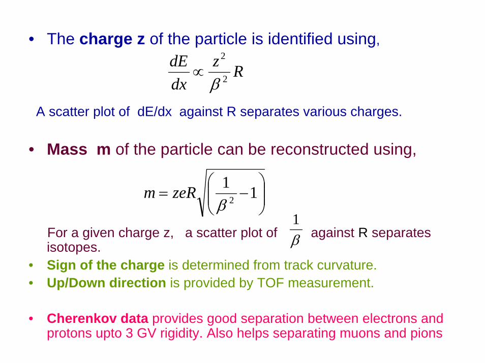
• The charge z of the particle is identified using,
A scatter plot of dE/dx against R separates various charges.
• Mass m of the particle can be reconstructed using,
For a given charge z, a scatter plot of against R separates isotopes.
• Sign of the charge is determined from track curvature.• Up/Down direction is provided by TOF measurement.
• Cherenkov data provides good separation between electrons and protons upto 3 GV rigidity. Also helps separating muons and pions
RzdxdE
2
2
β∝
⎟⎟⎠
⎞⎜⎜⎝
⎛−= 11
2βzeRm
β1
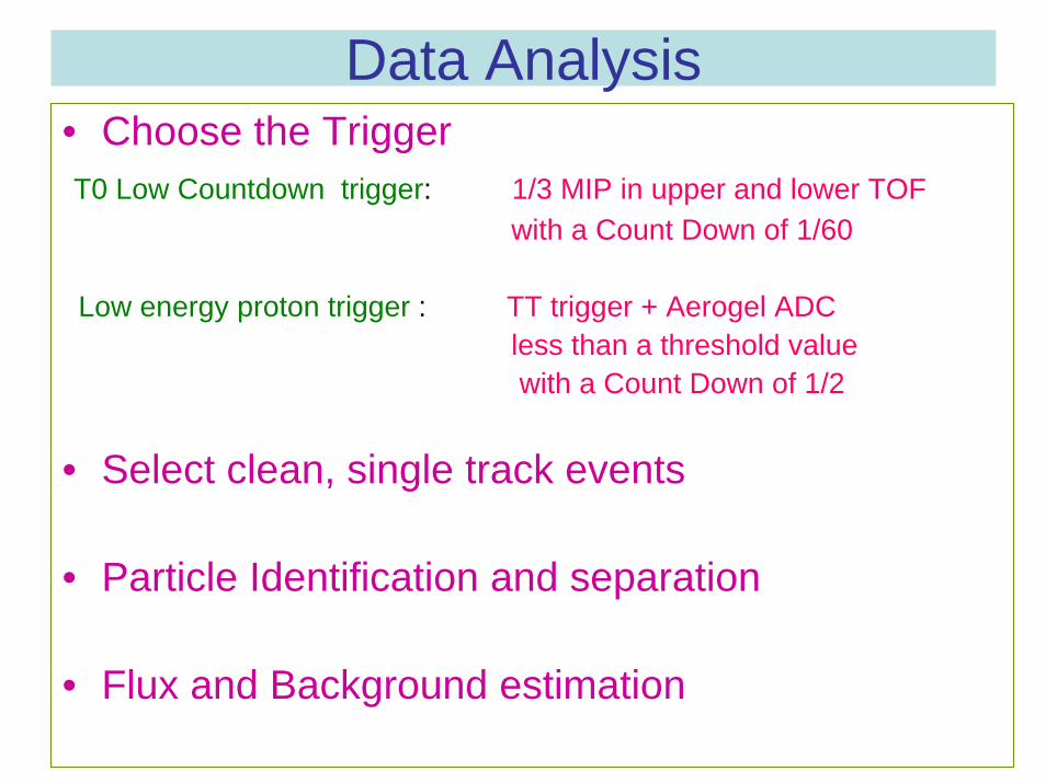
Data Analysis• Choose the TriggerT0 Low Countdown trigger: 1/3 MIP in upper and lower TOF
with a Count Down of 1/60
Low energy proton trigger : TT trigger + Aerogel ADC less than a threshold valuewith a Count Down of 1/2
• Select clean, single track events
• Particle Identification and separation
• Flux and Background estimation
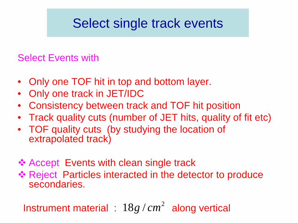
Select single track events
Select Events with
• Only one TOF hit in top and bottom layer.• Only one track in JET/IDC• Consistency between track and TOF hit position• Track quality cuts (number of JET hits, quality of fit etc) • TOF quality cuts (by studying the location of
extrapolated track)
Accept Events with clean single trackReject Particles interacted in the detector to produce secondaries.
Instrument material : along vertical 2/18 cmg
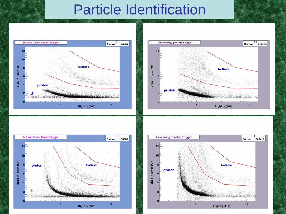
Particle Identification
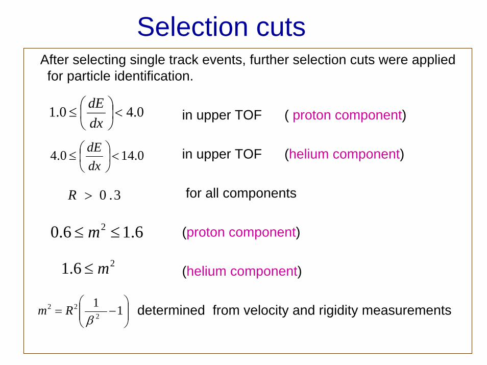
Selection cutsAfter selecting single track events, further selection cuts were applied for particle identification.
in upper TOF ( proton component)
in upper TOF (helium component)
for all components
(proton component)
(helium component)
determined from velocity and rigidity measurements
0.40.1 <⎟⎠⎞
⎜⎝⎛≤
dxdE
0.140.4 <⎟⎠⎞
⎜⎝⎛≤
dxdE
3.0>R
26.1 m≤
6.16.0 2 ≤≤ m
⎟⎟⎠
⎞⎜⎜⎝
⎛−= 11
222
βRm
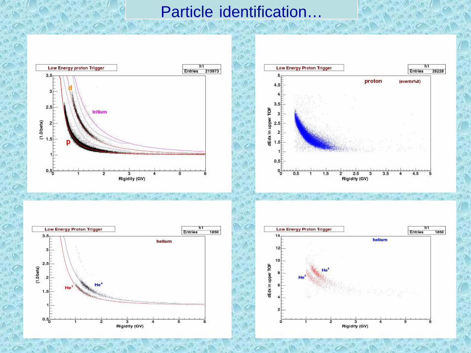
Particle identification…
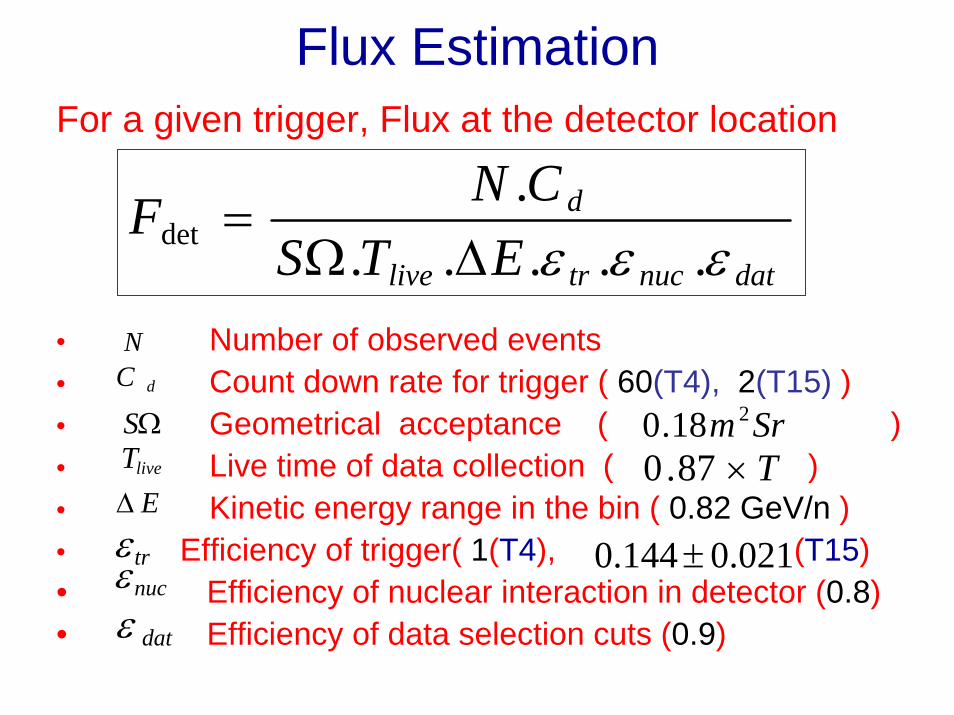
Flux EstimationFor a given trigger, Flux at the detector location
• Number of observed events• Count down rate for trigger ( 60(T4), 2(T15) )• Geometrical acceptance ( )• Live time of data collection ( )• Kinetic energy range in the bin ( 0.82 GeV/n )• Efficiency of trigger( 1(T4), (T15) • Efficiency of nuclear interaction in detector (0.8)• Efficiency of data selection cuts (0.9)
datnuctrlive
d
ETSCNF
εεε ......
det ∆Ω=
NdC
ΩSliveTE∆
trεnucεdatε
Srm 218.0T×87.0
021.0144.0 ±
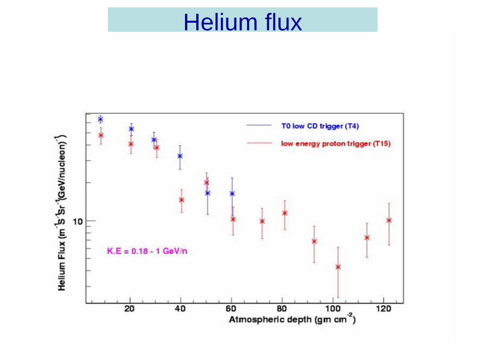
Helium flux
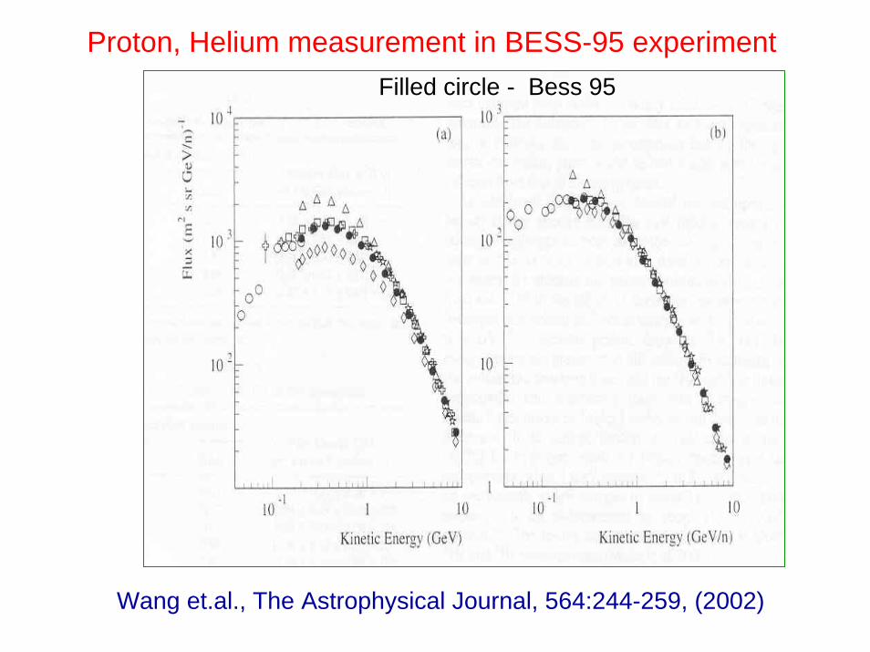
Proton, Helium measurement in BESS-95 experimentFilled circle - Bess 95
Wang et.al., The Astrophysical Journal, 564:244-259, (2002)
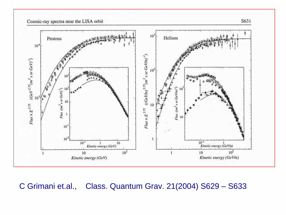
C Grimani et.al., Class. Quantum Grav. 21(2004) S629 – S633
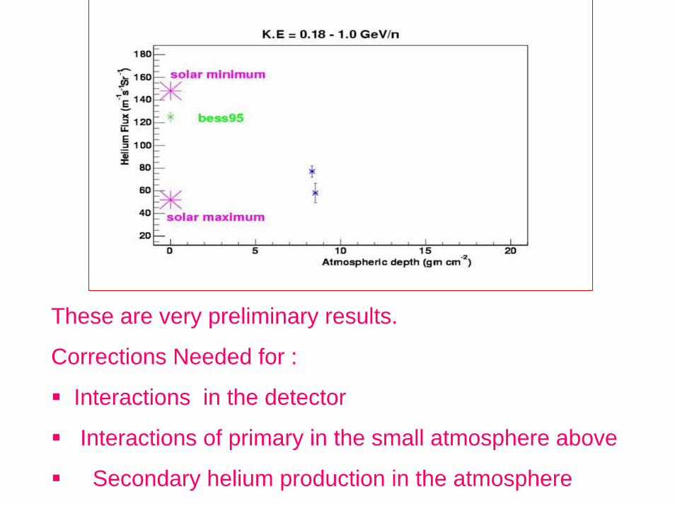
These are very preliminary results.
Corrections Needed for :
Interactions in the detector
Interactions of primary in the small atmosphere above
Secondary helium production in the atmosphere
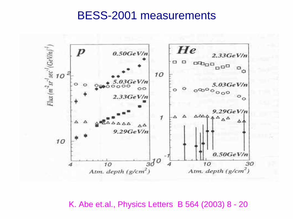
BESS-2001 measurements
K. Abe et.al., Physics Letters B 564 (2003) 8 - 20
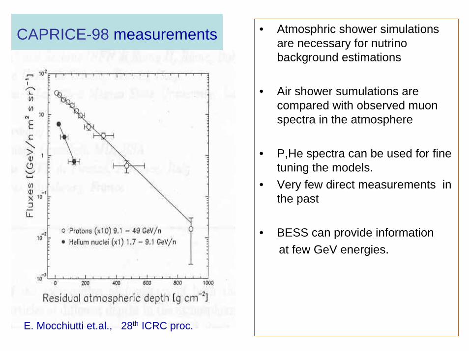
CAPRICE-98 measurements • Atmosphric shower simulations are necessary for nutrinobackground estimations
• Air shower sumulations are compared with observed muonspectra in the atmosphere
• P,He spectra can be used for fine tuning the models.
• Very few direct measurements in the past
• BESS can provide informationat few GeV energies.
E. Mocchiutti et.al., 28th ICRC proc.
Conclusions
• BESS 1999 flight gave a good sample of proton and helium events at various atmospheric depths.
• Preliminary results from He data (<1 GeV/n) are encouraging.
• A very large sample of proton data in the whole atmospheric depth is separated.
• Accurate estimation of p,He flux and background estimations will be done in the coming months.

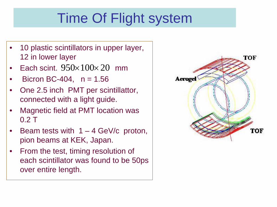
Time Of Flight system
• 10 plastic scintillators in upper layer, 12 in lower layer
• Each scint. mm• Bicron BC-404, n = 1.56• One 2.5 inch PMT per scintillattor,
connected with a light guide.• Magnetic field at PMT location was
0.2 T• Beam tests with 1 – 4 GeV/c proton,
pion beams at KEK, Japan.• From the test, timing resolution of
each scintillator was found to be 50ps over entire length.
20100950 ××
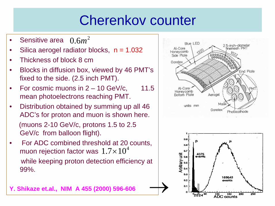
Cherenkov counter• Sensitive area • Silica aerogel radiator blocks, n = 1.032• Thickness of block 8 cm• Blocks in diffusion box, viewed by 46 PMT’s
fixed to the side. (2.5 inch PMT).• For cosmic muons in 2 – 10 GeV/c, 11.5
mean photoelectrons reaching PMT.• Distribution obtained by summing up all 46
ADC’s for proton and muon is shown here.(muons 2-10 GeV/c, protons 1.5 to 2.5 GeV/c from balloon flight).
• For ADC combined threshold at 20 counts, muon rejection factor was while keeping proton detection efficiency at 99%.
Y. Shikaze et.al., NIM A 455 (2000) 596-606
26.0 m
4107.1 ×
→
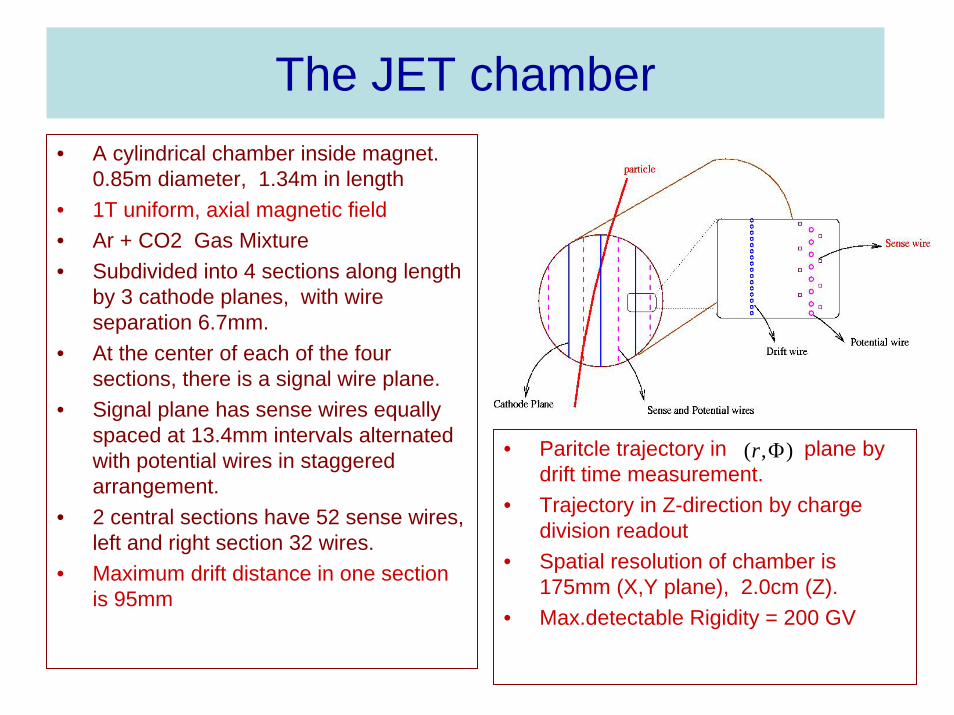
The JET chamber• A cylindrical chamber inside magnet.
0.85m diameter, 1.34m in length• 1T uniform, axial magnetic field • Ar + CO2 Gas Mixture• Subdivided into 4 sections along length
by 3 cathode planes, with wire separation 6.7mm.
• At the center of each of the four sections, there is a signal wire plane.
• Signal plane has sense wires equally spaced at 13.4mm intervals alternated with potential wires in staggered arrangement.
• 2 central sections have 52 sense wires, left and right section 32 wires.
• Maximum drift distance in one section is 95mm
• Paritcle trajectory in plane by drift time measurement.
• Trajectory in Z-direction by charge division readout
• Spatial resolution of chamber is 175mm (X,Y plane), 2.0cm (Z).
• Max.detectable Rigidity = 200 GV
),( Φr
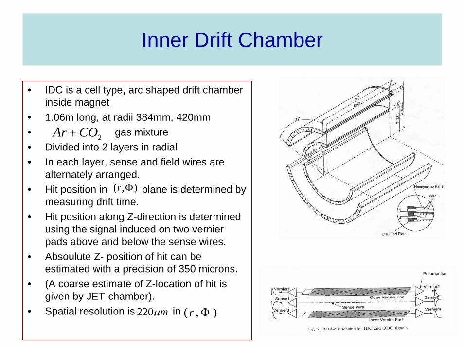
Inner Drift Chamber
• IDC is a cell type, arc shaped drift chamber inside magnet
• 1.06m long, at radii 384mm, 420mm• gas mixture• Divided into 2 layers in radial• In each layer, sense and field wires are
alternately arranged.• Hit position in plane is determined by
measuring drift time.• Hit position along Z-direction is determined
using the signal induced on two vernierpads above and below the sense wires.
• Absoulute Z- position of hit can be estimated with a precision of 350 microns.
• (A coarse estimate of Z-location of hit is given by JET-chamber).
• Spatial resolution is in
),( Φr
2COAr +
),( Φrmµ220
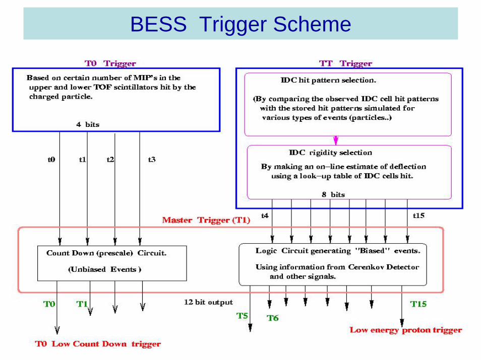
BESS Trigger Scheme