Embed Size (px)
Citation preview

1
Synthesis and photoreactivity of -diketone-type
precursors of acenes and their use in organic-device
fabrication
Mitsuharu Suzuki a,*, Tatsuya Aotake a, Yuji Yamaguchi b, Nao Noguchi c,
Haruyuki Nakano c,*, Ken-ichi Nakayama b,d,*, Hiroko Yamada a,d,**
aGraduate School of Materials Science, Nara Institute of Science and Technology, 8916-5, Takayama-
cho, Ikoma 630-0192, Japan
bDepartment of Electrical Devices, Graduate School of Science and Engineering, Yamagata University,
Yonezawa 992-8510, Japan
cDepartment of Chemistry, Graduate School of Sciences, Kyushu University, Fukuoka 812-8581, Japan
dCREST, JST, 7 Goban-cho, Chiyoda-ku 102-0076, Japan
___________________________________________________________________________________
* Corresponding author.
** Corresponding author. (tel.: +81-743-72-6041, fax.: +81-743-72-6042)
E-mail addresses: [email protected] (M. Suzuki); [email protected] (H. Nakano);
[email protected] (K. Nakayama); [email protected] (H. Yamada)

2
Highlights
- Synthesis and reactivity of -diketone-type acene precursors are reviewed.
- Preparation of large or functionalized acenes via -diketones is overviewed.
- The mechanism of photoinduced decarbonylation of -diketones is discussed.
- Fabrication of acene-based devices by the photoprecursor method is introduced.
Keywords
acenes, pentacene, decarbonylation, photoprecursor method, organic electronics, solution processes
Abbreviations
AFM, atomic force microscopy; BHJ, bulk heterojunction; CIS, configuration interaction singles; DBU,
1,8-diazabicyclo[5.4.0]undec-7-ene; DCB, o-dichlorobenzene; DIBAL, diisobutylaluminium hydride;
DDQ, 2,3-dichloro-5,6-dicyanobenzoquinone; DFT, density functional theory; DMSO, dimethyl
sulfoxide; EQE, external quantum efficiency; FET, field effect transistor; FF, fill factor; HOMO,
highest occupied molecular orbital; ICT, intramolecular charge transfer; IR, infrared; LED, light-
emitting diode; LUMO, lowest unoccupied molecular orbital; MD, molecular dynamics; MO, molecular
orbital; NMO, N-methylmorpholine-N-oxide; NMR, nuclear magnetic resonance; OPV, organic
photovoltaics; PCBM, [6,6]-phenyl-C61-butyric acid methyl ester; PCE, photo-conversion efficiency;
PES, potential energy surface; PMMA, poly(methyl methacrylate); RHF, restricted Hartree–Fock; TCB,
trichlorobenzene; TD, time-dependent; TEMPO, 2,2,6,6-tetramethylpiperidine-1-oxyl; TFAA,
trifluoroacetic anhydride; UV, ultraviolet; vis, visible; XRD, x-ray diffractometry;
3
Abstract
Acenes are highly promising p-type organic semiconductors, and have been the subject of intense
studies. However, acenes are often low in solubility and stability, which poses major obstacles in the
synthesis and processing of this class of compounds. In order to overcome the problem, a series of -
diketone-type acene precursors have been developed. These precursors are generally more soluble and
stable than the corresponding acene compounds, and their quantitative conversion can be achieved
simply by photoirradiation both in solution and in the solid state. Further, the irreversible photoinduced
removal of the -diketone unit can be used to alter the optoelectronic properties of fluorophores. This
review overviews the synthesis and photochemical properties of -diketone-type acene precursors, as
well as their use as intermediates in preparation of large acenes or highly functionalized acene
derivatives. Computational studies on the mechanism of -diketone photolysis and the use of -
diketone derivatives in fabrication of organic devices are also summarized in this review.

4
Contents
1. Introduction
2. Synthesis and properties of -diketone-type precursors of acenes
2.1. Background chemistry
2.2. -Diketone-type precursors of unsubstituted acenes
2.2.1. Precursors to pentacene
2.2.2. Precursors to larger acenes
2.3. -Diketone-type precursors of substituted acenes
2.3.1. Synthesis of end-substituted pentacenes via -diketone-type precursors
2.3.2. Combination with other chromophores
3. Mechanism of the -diketone photolysis
3.1. Mechanism of benzene diketone photolysis
3.2. Mechanism of anthracene- and pentacene-diketone photolysis
3.3. Summary on the mechanism of -diketone photolysis
4. Device fabrication by the photoprecursor method
4.1. Film preparation
4.2. Organic field-effect transistors
4.3. Organic photovoltaic cells
5. Summary and concluding remarks

5
1. Introduction
Solution-processable organic semiconductors hold much promise as active components in
optoelectronic devices owing to their potential for permitting large-scale fabrication of thin, flexible,
and lightweight devices based on simple processing techniques [1–21]. Many research laboratories have
devoted considerable efforts towards this end, and the progress during the past two decades is
significant as can be manifested by, for example, the current use of organic light-emitting diode displays
in commercial devices. However, the commercialization of organic devices is still limited, and most
other organic devices such as organic photovoltaic cells and organic field-effect transistors remain
elusive in the market. Further advance in both material design and device-fabrication process is required
before various types of organic devices become widely available so that society can fully appreciate
their great advantages.
Acenes, which can be described as linearly fused benzene rings (Figure 1), have been the subject of
intense studies in the organic semiconductor research [22–25]. For example, unsubstituted pentacene (1)
is one of the routinely employed p-type semiconductors, which shows carrier mobilities of over 5 cm2
V–1 s–1 [26]—among the highest charge carrier mobilities obtained with organic materials so far.
However, unsubstituted acenes are not necessarily well-suited for commercial applications largely
because of their low solubility and stability; pentacene and larger acenes are hardly soluble in common
organic solvents and easily oxidized in air to form the corresponding quinones [22,23,27]. These
shortcomings keep the preparation and processing of unsubstituted acenes from being scalable and cost-
effective. Accordingly, one of the main subjects in acene chemistry is to develop stable and solution-
processable derivatives without adversely affecting their intrinsic useful properties as organic
semiconductors.

6
Figure 1. General structure of acenes (top-left), structures of acene series from pentacene (1) to
nonacene (5) and the soluble derivative of pentacene developed by Anthony et al. (6).
A milestone in the development of device-oriented acene derivatives is the synthesis of 6,13-
bis(triisopropylsilylethynyl)pentacene (6, Figure 1) reported by Anthony and coworkers in 2001 [28].
Derivative 6 is soluble in common organic solvents and stable under ambient conditions allowing not
only deposition via simple solution-based techniques, but also easy purification after synthesis. In
addition, the compound adopts a “brickwork arrangement” in the crystalline state, in which the face-to-
face contact between pentacene units extends two dimensionally. This packing motif is favorable for
charge carrier transportation; indeed, Bao and coworkers demonstrated in their recent report that the
hole mobility in solution-processed FET devices based on compound 6 can be as high as 11 cm2 V–1 s–1
[29]. This value is higher than those observed for the parent pentacene or for amorphous silicon
(typically in the order of 1 cm2 V–1 s–1) [30]. Following the development of compound 6, many
substituted pentacenes and larger acenes have been evaluated as summarized in previous reviews [22–
24].
Another approach to achieve both solution processability and high device performance with acenes is
to introduce solubilizing groups that are cleanly removable after deposition [31]. A pioneering work
along this line was reported by Müllen and coworkers in 1996 [32]. The authors developed a
tetrachlorobenzene–pentacene adduct (7, Figure 2), which can be deposited as a solution and converted

7
to the parent pentacene (1) in the film via thermally induced retro Diels–Alder reaction at 180 °C.
Charge carrier mobilities as high as 9 × 10⁻³ cm2 V–1 s–1 were observed in the resulting films. Following
this, other thermolabile derivatives of pentacene (8–14) were proposed by different groups [33–40], and
hole mobilities of up to 0.89 cm2 V–1 s–1 [33] was achieved in the resulting pentacene films. In some
cases, the thermolytic conversion to pentacene proceeded at temperatures as low as 120–130 °C
[33,35,37], suggesting the potential compatibility of this method with plastic substrates.
Figure 2. Structures of the known thermo-convertible precursors of pentacene [32–36,39,41].
Photolysis, instead of thermolysis, can be also used for the post-deposition conversion of soluble
precursors to insoluble acenes. (This methodology is called ‘photoprecursor method’ in the followings
of this review.) Since photolysis can be performed at ambient temperature or lower, its scope for
applicable substrates would be much wider compared to that of thermolysis. In addition, the
photoprecursor method may permit light pattering of the active layer by employing the already well-
established photolithography techniques. These advantages motivated the development of
S O
N
S
O
O O
N
N
CO2R
CO2R
O
CO2EtEtO2C
O
Cl
Cl
Cl
Cl
7
N
S
O
O
8
N
S
O
O
12
9 10
11
13 14
R = Me (11a), Et (11b), t-Bu (11c)
8
photoconvertible acene precursors. In this context, Chow and coworkers prepared monoketone
derivatives of acenes including compound 9, which can be transformed to the parent acenes both by
thermolysis and photolysis [41–47]. This review specifically focuses on another class of photo-
convertible precursors of acenes; i.e., -diketone-type precursors. The following sections summarize the
synthesis and photochemical properties of the -diketone-type precursors reported so far. Described
also are computational investigation on the mechanism of their photoconversion and their use in the
fabrication of acene-based organic devices.
2. Synthesis and photoreactivity of -diketone-type precursors of acenes
2.1. Background chemistry
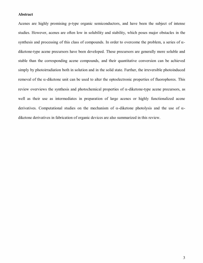
In 1968, Bryce-Smith and Gilbert reported the photolytic decarbonylation of -diketone 15 to form
tetrachloro-o-terphenyl 21 both in solution and in the crystalline state under visible light (Scheme 1)
[48]. While the thermal decarbonylation of monoketone compounds was already well-documented by
then [49], the photoinduced decarbonylation of -diketones had been unknown until this report. Almost
at the same time, Strating and coworkers reported that -diketones 16–19 underwent smooth photolysis
to form the corresponding aromatic compounds (Scheme 1) [50]. The reactions were performed in
benzene solutions using a high-pressure mercury lamp to yield compound 22–25 in quantitative, 97%,
95%, and 43% yield, respectively. They also found that compound 20 could undergo photoinduced
decarbonylation to form cyclohexadiene 26, indicating that aromatic stabilization in the product would
not necessarily be the requirement for this type of photolysis. A while later, Pyle et al. applied this
method to the synthesis of unsymmetrically substituted chlorobiphenyls 23 and 27 with the aim of using
these differently chlorinated biphenyls in toxicological studies (Scheme 1 and Figure 3) [51]. The
cleanliness of the photoinduced decarbonylation allowed easy workup and isolation to provide good
overall yields and high purity of the final products, which is critical in the toxicological studies. A
different group also applied this method to prepare highly substituted derivatives of indene and benzene

9
(Scheme 2) [52]. Although the synthetic application of the photolytic decarbonylation of -diketones
has been rather limited, the above examples clearly show its usefulness in the synthesis of highly
functionalized small acenes and other related classes of compounds. The mechanism of this
decarbonylation has been under investigation for long since immediately after the discovery of the
reaction [50,53–55], which will be described separately in Section 3.
Scheme 1. Photoinduced decarbonylation of -diketones reported by Bryce-Smith and Gilbert [48], and
Strating et al. [50]
Cl
Cl
OO
Cl
ClCl
Cl
Cl
Cl
hn
–2CO
OO
Cl
Cl
OO
Cl
Cl
OO
OHHO
OO
OO
Cl
Cl
Cl
Cl
OH
HO
O
O
hn
–2CO
hn
–2CO
hn
–2CO
hn
–2CO
15 21
16
17
18
19
22
23
24
25
Cl
Cl
OO
Cl
ClCl
Cl
Cl
Cl
hn
–2CO
20 26
10
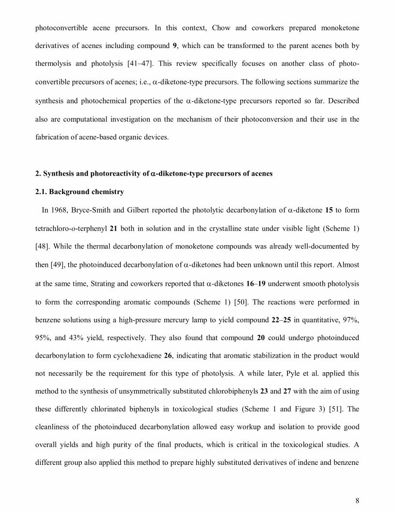
Figure 3. Unsymmetrically chlorinated biphenyls synthesized by Pyle and coworkers via photolytic
decarbonylation [51].
Scheme 2. Synthesis of highly functionalized indene and benzene derivatives via photolysis of -
diketones [52].
2.2. -Diketone-type precursors of unsubstituted acenes
2.2.1. Precursors to pentacene
The use of -diketone derivatives as soluble precursors of acenes was pioneered by Ono, Uno,
Yamada and coworkers [56–58]. Synthesis of the symmetric -diketone precursor of pentacene (37,
Scheme 3) was started with the double coupling of tetramethylene 32 and benzyne, followed by
oxidative aromatization by the action of 2,3-dichloro-5,6-dicyanobenzoquinone (DDQ) to form
intermediate 33. Dihydroxylation of the etheno bridge with OsO4 provided diol 36, which was then
subjected to the Swern oxidation conditions to form the target -diketone 37 (Scheme 3, route A).
Alternatively, 37 could be also synthesized from the parent pentacene (1) via the Diels–Alder addition
with vinylene carbonate followed by hydrolysis under basic conditions (route B). In the latter route, the
H
OO
hn
–2COH
R4R3
R2
R1
R3R4
R1
R2
DDQ
28a–28f 29a–29f
R1 R2 R3 R4
a t-Bu Pht-Bu Ph
b t-Bu PhH Ph
c H PhOCH3 Ph
d t-Bu Ht-Bu Ph
e t-Bu HH Ph
f t-Bu Ht-Bu 4-MeOC6H4
g t-Bu CH3t-Bu Ph
e t-Bu CH3H Ph
tBu
tBu
R5
R6
OO
tBu
tBu
R5
R6
R5 R6
a CO2Me CO2Me
b H CH2OH
c Ph H
d H Ph
hn
–2CO
30a–30d 31a–31d
11
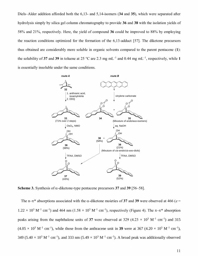
Diels–Alder addition afforded both the 6,13- and 5,14-isomers (34 and 35), which were separated after
hydrolysis simply by silica gel column chromatography to provide 36 and 38 with the isolation yields of
58% and 21%, respectively. Here, the yield of compound 36 could be improved to 88% by employing
the reaction conditions optimized for the formation of the 6,13-adduct [57]. The diketone precursors
thus obtained are considerably more soluble in organic solvents compared to the parent pentacene (1):
the solubility of 37 and 39 in toluene at 25 °C are 2.3 mg mL–1 and 0.44 mg mL–1, respectively, while 1
is essentially insoluble under the same conditions.
Scheme 3. Synthesis of -diketone-type pentacene precursors 37 and 39 [56–58].
The n–* absorptions associated with the -diketone moieties of 37 and 39 were observed at 466 ( =
1.22 × 10³ M–1 cm–1) and 464 nm (1.58 × 10³ M–1 cm–1), respectively (Figure 4). The –* absorption
peaks arising from the naphthalene units of 37 were observed at 329 (4.23 × 10³ M–1 cm–1) and 315
(4.05 × 10³ M–1 cm–1), while those from the anthracene unit in 39 were at 367 (4.20 × 10³ M–1 cm–1),
349 (5.40 × 10³ M–1 cm–1), and 333 nm (5.49 × 10³ M–1 cm–1). A broad peak was additionally observed
OHOH
OO
O
OO
O
OHOH
OO
OO
1. anthranic acid, isoamylnitrite2. DDQ
vinylene carbonate
+
(71% over 2 steps)
132
33 34 35
36(98%)
37(43%)
38(21%)
39(52%)
36(58%)
+
OsO4, NMO aq. NaOH
TFAA, DMSO TFAA, DMSO
route A route B
(Mixuture of endo/exo-isomers)
(Mixuture of cis-endo/cis-exo-diols)

12
at 386 nm (2.98 × 10³ M–1 cm–1) for 39, which was ascribed to the intramolecular charge-transfer (ICT)
from the anthracene moiety to the -diketone unit based on the solvent dependence of photoabsorption
behavior and DFT calculations [58].
Figure 4. UV–vis absorption spectra of 1 (blue) and its -diketone-type precursors 37 (black) and 39
(red) in toluene [58].
The photolysis of -diketones 37 and 39 to form pentacene (1) proceeded smoothly in toluene with
quantum yields (r) of 1.4 ± 0.3 and 2.3 ± 0.3%, respectively, when they were irradiated at 468 nm
corresponding to the n–* absorption of -diketone unit (Figure 5). In the case of 39, the photolysis
could be also induced by 405-nm light, which corresponds to the ICT absorption, with a r of 2.4 ±
0.3%. On the other hand, the reaction efficiency was considerably lower in acetonitrile: the observed r
values were 0.80 ± 0.12 and 0.28 ± 0.10% for 37 and 39, respectively, under irradiation at 468 nm. The
reaction was similarly inefficient when compound 39 was irradiated at 405 nm in acetonitrile (r = 0.33
± 0.13%). The authors assumed that the lower r values in the more polar solvent, acetonitrile, would
be due to efficient electron transfer in the singlet-excited state to form a charge-separate species which
then decays to the ground state mainly via a nonproductive, radiationless pathway. In the less polar
solvent, toluene in this case, the charge-separate state would experience less stabilization, thereby being
located higher in energy. Consequently, the photoreaction pathway becomes more favorable, leading to
the higher r values.

13
Figure 5. Change in absorption spectra during the photolysis of -diketone-type pentacene precursors
37 (a) and 39 (b) in toluene [58].
The photoconversion of -diketone 37 to pentacene (1) was also conducted in a thin film under
exclusion of oxygen. The conversion was monitored through change in photoabsorption—the n–*
absorption at 470 nm disappeared upon photoirradiation, while new peaks emerged at 585, 627, and 648
nm in good agreement with the reported data for deposited samples of 1 [59]. The quantitative
conversion of 37 was confirmed by absence of the carbonyl stretch in the IR spectrum of the resulting
film. Unsymmetrical isomer 39 also underwent the photoinduced decarbonylation in a thin film, as
indicated by change in photoabsorption. In this case, however, the solid-state UV–vis spectrum of pre-
reaction sample showed only very broad, featureless absorption without any well-structured peaks. The
authors supposed that the significant broadening of photoabsorption peaks would be due to the strong
– interaction between the molecules of 39 in the film. Indeed, compound 39 has higher crystallinity
and tighter crystal packing compared to symmetric isomer 37, even though the overall crystal-packing
motifs are essentially the same for those two compounds. The absorption spectrum of post-reaction film
14
of 39 was also relatively featureless, but characteristic peaks for the expected product 1 were observed
at 560 and 610 nm.
2.2.2. Precursors to larger acenes
While the parent pentacene (1) is widely available from commercial sources, larger acenes had been
elusive even in research laboratories until very recently when the photoprecursor method was employed
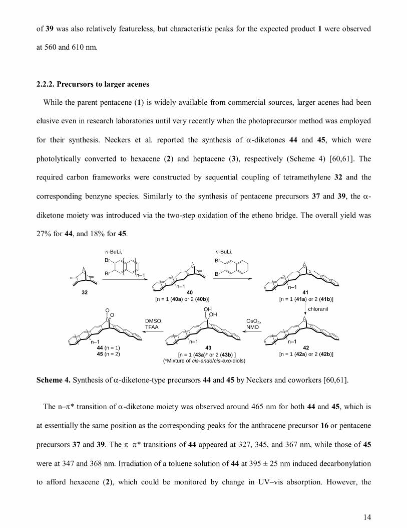
for their synthesis. Neckers et al. reported the synthesis of -diketones 44 and 45, which were
photolytically converted to hexacene (2) and heptacene (3), respectively (Scheme 4) [60,61]. The
required carbon frameworks were constructed by sequential coupling of tetramethylene 32 and the
corresponding benzyne species. Similarly to the synthesis of pentacene precursors 37 and 39, the -
diketone moiety was introduced via the two-step oxidation of the etheno bridge. The overall yield was
27% for 44, and 18% for 45.
Scheme 4. Synthesis of -diketone-type precursors 44 and 45 by Neckers and coworkers [60,61].
The n–* transition of -diketone moiety was observed around 465 nm for both 44 and 45, which is
at essentially the same position as the corresponding peaks for the anthracene precursor 16 or pentacene
precursors 37 and 39. The –* transitions of 44 appeared at 327, 345, and 367 nm, while those of 45
were at 347 and 368 nm. Irradiation of a toluene solution of 44 at 395 ± 25 nm induced decarbonylation
to afford hexacene (2), which could be monitored by change in UV–vis absorption. However, the
n-BuLi,
32 40
Br
Br
n-BuLi,
n–1
Br
Br
n–1 n–1
chloranil
n–1n–1
OHOHO
ODMSO,TFAA
41
4243
OsO4,NMO
44 (n = 1)45 (n = 2)
n–1
[n = 1 (40a) or 2 (40b)] [n = 1 (41a) or 2 (41b)]
[n = 1 (42a) or 2 (42b)]
(*Mixture of cis-endo/cis-exo-diols)[n = 1 (43a)* or 2 (43b) ]
15
product was highly unstable and quickly converted to the corresponding dimeric and oxidized species
under the reaction conditions (concentration < 10–4 M), preventing detailed study of 2. On the other
hand, 2 could be kinetically stabilized in a matrix of poly(methyl methacrylate) (PMMA). The authors
prepared a thin film (ca. 0.5 mm thickness) of PMMA containing 3.5 × 10⁻³ M of -diketone 44.
Reaction monitoring through photoabsorption spectra indicated the smooth formation of 2 in the film,
which was further confirmed by mass spectroscopy. The product could be retained in the polymer
matrix overnight under ambient conditions [60]. Detection and characterization of heptacene (3) were
even more challenging. The formation of 3 could not be observed directly in the photolysis of 45 in
solution indicating its extremely unstable nature, and accordingly only the polymer matrix method
allowed unambiguous characterization of the product. Irradiation of 45 dispersed in a thin film of
PMMA (3.0 × 10⁻³ M, 0.5 mm thickness) resulted the appearance of new structured absorption ranging
from 600 to 825 nm with the maximum around 760 nm, which was assigned to the –* transition of 3.
The formation of 3 was also confirmed by mass spectroscopy, and the product was stable up to 4 h in
the PMMA matrix. Following these synthetic achievements, the same group investigated the properties
of 3 in the solidified inert-gas matrix at 10 K [61,62]. In a separate report, the same team applied the
acene-containing polymer matrix system to evaluate the oxygen permeability of polymers [63].
More recently, Bettinger et al. reported the preparation of octacene (4) and nonacene (5) by photolysis
of the corresponding -diketone-type precursors 49 and 50, respectively (Scheme 5) [64]. These
photoprecursors were designed not to contain subunits longer than anthracene for the sake of ensuring
stability and solubility, and thus two -diketone bridges per molecule were introduced. Another
difference in this synthesis from the previous examples is that a radical-based method was employed for
the final oxidation step. Oxidation under the Swern conditions or by o-iodoxybenzoic acid turned out to
be ineffective in this specific case, and instead the combination of 2,2,6,6-tetramethylpiperidine-1-oxyl
and NaOCl was used. The photolysis of 50 to 5 proceeded in two steps via intermediate 51 under the
employed reaction conditions (Scheme 6). Upon the irradiation of visible light (> 360 nm), only one of

16
the two -diketone bridges was extruded to generate a hexacene subunit, while the complete photolysis
was achieved by the irradiation of UV light at 305–320 nm. Irradiation at an even shorter wavelength of
185 nm induced photo-ionization. The shorter analogue 49 and its stereoisomer showed similar
photoreactivity.
The examples described above clearly demonstrate the power of photoprecursor approach in the
synthesis of large acenes, which provides an efficient access to this interesting class of compounds and
enables investigation of their properties. Further exploration for better processing techniques or for
kinetically stabilized derivatives would allow the practical use of acenes in devices. Along these lines,
the recent beautiful work by Chow and coworkers is of special interest, where the authors succeeded in
the preparation of single-crystalline samples of hexacene (2) from a monoketone-type precursor 52 via
thermolytic decarbonylation (Scheme 7) [45]. The FET devices based on thus obtained single crystals
showed hole mobilities of up to 4.28 cm2 V–1 s–1. The same group also reported monoketone-type
precursors 9, 53, and 54 which are both thermally and photochemically convertible to the corresponding
acenes (Scheme 7).
Br
Br
n-BuLi,
Br
Br
Br
Br
Br
Br
n-BuLi,
O
O
OO
1. chloranil2. OsO4, NMO3. TEMPO, NaOCl
32 40a 46
(2:1)
Br
Br
n-BuLi,
Br
Br (1:1)
n-BuLi,
same as left
n–1
48 (+ stereoisomer)47 (+ stereoisomer)
49 (+ stereoisomer, n = 1)50 (+ stereoisomer, n = 2)
hn, 30 K
–4COOctacene (4)Nonacene (5)

17
Scheme 5. Synthesis of photoprecursors 49 and 50 by Bettinger and coworkers [64].
Scheme 6. Photochemical synthesis of nonacene (5) and its photoinduced ionization in a solid argon
matrix at 30 K [64].

18
Scheme 7. Examples of monoketone-type precursors of acenes reported by Chow and coworkers
[41,42,44–46].
2.3. -Diketone-type precursors of substituted acenes
2.3.1. Synthesis of end-substituted pentacenes via -diketone-type precursors
As described in Introduction, the use of parent acenes in practical applications has been largely
hampered by their instability and insolubility. Various derivatives of acenes, especially of pentacene (1),
have been synthesized in order to improve the processability as well as to tune the optoelectronic
properties and solid-state organization. A classical synthetic approach to functionalized acenes is the
nucleophilic addition of organolithium reagents or organomagnesium halides to the corresponding
quinone derivatives followed by reductive aromatization [65,66]. This approach has been employed for
a wide variety of 6,13-substituted pentacenes including the 6,13-bis(triisopropylsilylethynyl)pentacene
(6) and 6,13-connected oligomeric pentacene derivatives [22,24]. Another approach is the homologation
method [67–71], which allows facile access to end-functionalized derivatives. Alternatively, one can
employ the -diketone route, where an -diketone derivative is first synthesized via the addition of
O
52
hn or D
–CO
2
O
9
O
53
O
54X
1
55
X
hn or D
–CO
hn or D
–CO
hn or D
–CO
X = Cl (54a), Br (54b) X = Cl (55a), Br (55b)
19
tetramethylene 32 and required benzyne units, followed by the oxidation of etheno bridge. The resulting
-diketone is then subjected to decarbonylation to form the target pentacene derivative. Similarly to the
homologation method, this approach is suitable for the synthesis of end-substituted pentacenes, because
derivatization can be achieved by simply changing the benzyne unit to be coupled with 32. This latter
approach is described in more detail in this section.
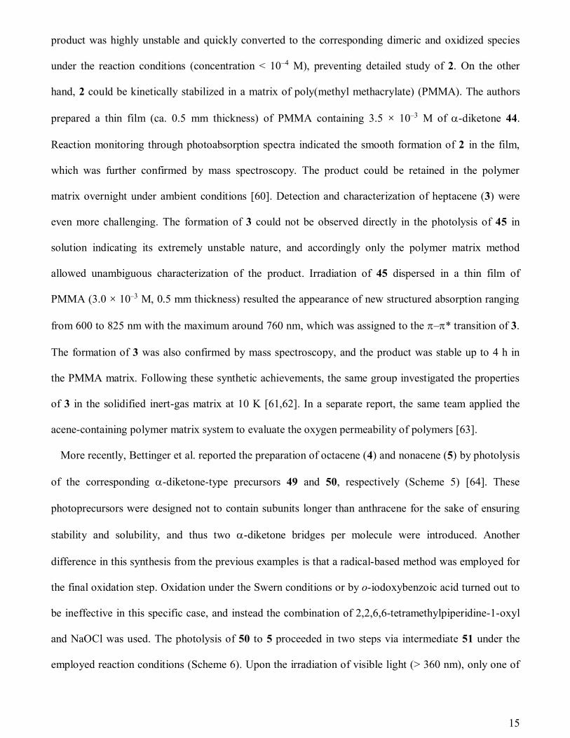
In 2005, Yamada et al. reported the synthesis of 2,9- and 2,10-dibromopentacenes (59) via the photo-
decarbonylation of the corresponding -diketone-type precursors (Scheme 8) [57]. The authors prepared
a mixture of 2,9- and 2,10-dibromo-6,13-ethanopentacenes (57) from 2-amino-5-bromobenzoic acid
(56) and tetramethylene 32. Sequential oxidation of 57 led to the formation of -diketone 58. Here, the
2,9- and 2,10-isomers were hard to separate, and the product was isolated as a mixture of the two
regioisomers. The photoconversion of 58 was performed in a degassed toluene solution by using a
super-high-pressure mercury lamp (500 W) through UV and IR cut-off filters. A purple precipitate
appeared upon photoirradiation, which was identified as the corresponding isomeric mixture of
dibromopentacenes (59) based on mass spectroscopic analysis. The isolation yield of this photolysis was
79%.
Scheme 8. Synthesis of dibromopentacenes by Yamada et al. [57]. The product was obtained as a
mixture of 2,9- and 2,10-isomers.
Neckers and coworkers reported photochemical syntheses of 2,3-di- and 2,3,9,10-tetrasubstituted
pentacenes via the photolysis of -diketone-type precursors (Scheme 9) [72,73]. The synthesis of
tetrasubstituted pentacenes 66a–66c was started with the double Diels–Alder addition between
NH2
CO2H
isoamyl nitrite Br
BrBr
5657
OO
BrBr 58
1. DDQ2. OsO4
3. TFAA, DMSO
32
Br
Br
59
hn
–2CO
Br
20
dibromobenzyne 61 and tetramethylene 32. On the other hand, the carbon framework of disubstituted
derivatives 71a and 71b was constructed by stepwise Diels–Alder reactions in which dibromo- and
unsubstituted benzynes were sequentially reacted with 32. After oxidative aromatization and
introduction of different aryl groups by Suzuki–Miyaura coupling, the etheno bridge was oxidized to -
diketone in two steps. The photoinduced decarbonylation of thus obtained precursors proceeded
smoothly to provide the target substituted pentacenes. In addition, 2,3,9,10-tetrabromopentacene (72)
was obtained by employing the same strategy.
These substituted pentacenes are generally more soluble compared to the parent pentacene (1),
allowing full monitoring of the photoinduced decarbonylation process in solution without precipitation
of the product over the course of the reaction. Indeed, the authors were able to monitor the
photoconversion of 70a by solution NMR, which clearly showed that the formation of pentacene 71a is
essentially quantitative without forming any by-products [72]. The formation of 71a was further
confirmed by mass spectrometry and photoabsorption spectroscopy. Those substituted pentacenes are
highly stable under inert atmosphere: the converted pentacenes survived in solution for one month
without showing any sign of dimerization or oxidation.

21
Scheme 9. Synthesis of 2,3-di- and 2,3,9,10-tetrasubstituted pentacenes by Neckers and coworkers
[72,73].
Br
Br
Br n-BuLi Br
60
Br Br
Br
Br
Br
Br
Br
Br
chloranil
1. OsO4, NMO2. TFAA, Et3N, DMSO3. hn
R1
R1
R1
R2
OO
R1
R1
R1
R2
R3
R3
R3
R3
OO
R3
R3
61
63
72
68
Br
Br
Br
Br
(32) (x 0.5 mol)
32(x 1 mol)
62 67
Suzuki–Miyauracoupling
Suzuki–Miyauracoupling
64a–64c 69a, 69b
65a–65c 70a, 70b
63
1. OsO4, NMO2. DMSO, TFAA, i-Pr2NEt
1. chloranil2. OsO4, NMO3. DMSO, TFAA, i-Pr2NEt
R1
R1
R1
R2
R3
R3
hn–2CO hn–2CO
66a–66c 71a, 71b
Br
Br
Br
Br
a: R1 = R2 = 2-tolyl
b: R1 = R2 = 4-t-BuC6H4
c: R1 = 2-tolyl, R2 = Br
a: R3 = 2-tolyl
b: R3 = 4-t-BuC6H4

22
In 2009, Lin et al. reported the homologation synthesis of end-substituted acenes, wherein an
[n]acene-ortho-dicarbaldehyde is converted to the corresponding [n+1]acene-ortho-dicarboxylate in
one-pot (Scheme 10a) [74]. The dicarboxylate product can be transformed to dicarbaldehyde via a
routine reduction–oxidation protocol, and then subjected to another iteration of elongation. In addition,
dicyanoacenes can be obtained in the same fashion by employing fumaronitrile as a coupling partner.
The authors successfully combined this strategy with the -diketone approach to obtain tetraethyl
2,3,9,10-pentacenetetracarboxylate (77, Scheme 10b), in which the bidirectional elongation of
tetracarbaldehyde 74 to form 75 was followed by the oxidation of etheno bridge to generate -diketone
76. The photolysis of 76 to 77 proceeded in 70–80% yield. The bidirectional elongation also provided
other etheno-bridged compounds 78–80 (Scheme 10c), indicating the usefulness of this strategy in
synthesizing a variety of electron-deficient acenes.
CO2Et
CO2Et
PR3,DBU,
CHO
CHO
CO2Et
CO2Et
MeO2C
CO2Me
CO2Me
MeO2C
EtO2C
EtO2C
CO2Et
CO2Et
1. DIBAL2. (COCl)2, Et3N, DMSO
NC
NC
CN
CN
NC
NC
CN
CN
EtO2C
EtO2C
CO2Et
CO2Et
OO
EtO2C
EtO2C
CO2Et
CO2Et
73
75
76
79
80
78
n–1
n–1
CN
CNn–1
PR3,CN
NC
(a) (b)
OHC
CHO
CHO
OHC
74
CO2Et
CO2Et
PR3,DBU,
1. OsO4, NMO2. (COCl)2, Et3N, DMSO,
hn–2CO
77
EtO2C
EtO2C
CO2Et
CO2Et
(c)

23
Scheme 10. Iterative synthesis of acenes via the homologation strategy reported by Lin and coworkers
[74].
Photochemical synthesis of 1,4,8,11-tetraaryl pentacenes 84a and 84b was reported by Yamada and
coworkers (Scheme 11) [75]. The synthesis was started with the preparation of the required 3,6-
diarylanthranilic acids (82a and 82b) in six steps from commercially available anhydride 81. Following
the regular Diels–Alder/oxidation sequence, 82a and 82b were converted to the target -diketone-type
precursors 83a and 83b, both of which underwent smooth photoinduced decarbonylation to form 84a
and 84b, respectively. Here again, the photolysis process could be monitored by 1H NMR and UV–vis
spectra to confirm quantitative conversion to the corresponding pentacene derivatives (Figure 6).
Scheme 11. Photosynthesis of 1,4,8,11-tetraaryl pentacenes 84a and 84b by Yamada and coworkers
[75].
O
Br
Br
O
O
R
R
6 steps
81 82a82b
OO
R
R
R
R
83a83b
a: R = phenylb: R = 2-thienyl
NH2
CO2H
1. isoamyl nitrite2.
32
1. DDQ2. OsO4
3. TFAA, DMSO, Et3N
hn
–2CO
R
R
R
R
84a84b

24
Figure 6. Change in NMR spectra during the photolysis of 83a in CDCl3.
Recently, Tönshoff and Bettinger employed the photoprecursor approach for synthesizing
tetramethoxy pentacene 86a and push–pull type pentacene derivatives 86b–86d (Scheme 12) [76]. The
synthesis of -diketones 85a–85d was achieved through a similar synthetic route as Scheme 9. The
photolysis proceeded smoothly both in argon matrix at 10 K and in CH2Cl2 solution. Progress of the
photolysis reactions was monitored through change in UV–vis absorption, which indicated clean
decarbonylation associated with isosbestic points. The clean, efficient formation of these interesting
derivatives would enable a systematic investigation of their solid-state packing and charge carrier
transport behavior.
Scheme 12. Photoprecursor approach to pentacene derivatives 86a–86d reported by Tönshoff and
Bettinger [76].
OO
MeO
MeO
R
R
hn–2CO
MeO
MeO
R
R
85a–85d
86a–86d
R = OMe (a), F (b), Br (c), CN (d)

25
2.3.2. Combination with other chromophores
The photoinduced decarbonylation is more than just a convenient synthetic means for preparing
acenes and their derivatives. The drastic change in electronic structure associated with the
decarbonylative aromatization is highly interesting in that it can irreversibly alter the (opto)electronic
properties of a compound. For example, Aotake et al. showed that nonfluorescent -diketone
derivatives 90a and 90b could be quantitatively converted to highly fluorescent anthracene–pyrene
dyads 91a and 91b via the photoinduced decarbonylation (Scheme 13) [77]. Aryl-substituted pyrenes
are generally highly fluorescent [78–80], and both 91a and 91b are not exceptional: the observed
fluorescent quantum yields in solution were 0.86 or higher, with the maximum of 0.99 observed for 91a
in benzonitrile. On the other hand, the -diketone derivatives are not fluorescent owing to the quenching
of pyrene excited state by the -diketone moiety. The authors also demonstrated that photoconversion
of these -diketones could proceed in poly(methyl methacrylate) (PMMA) films, allowing photo-
patterning as shown in Figure 7. The -diketone derivatives 90a and 90b were synthesized from 2-
bromoanthracene 87 in four steps (Scheme 13).
Scheme 13. Synthesis of nonfluorescent -diketone precursors 90a and 90b, and their photoconversion
to highly fluorescent anthracene–pyrene dyads 91a and 91b [77].
vinylenecarbonate O
O
O
Br
Br
OO
O
Ar
1. K2CO3
2. TFAA, DMSO, i-Pr2NEt
OO
Ar
Pd coupling
90a, 90b
87
88* 89a*, 89b*
91a
91b
orhn
–2CO
(*Mixture of endo/exo-isomers)
a: Ar = 1-pyrenylb: Ar = 1-pyrenylethynyl

26
Figure 7. Photopatterned film of poly(methyl methacrylate) containing 90a. The irradiated areas turn
fluorescent because of the photoinduced conversion of nonfluorescent 90a to highly fluorescent 91a.
Aotake et al. also designed masked tetracene derivatives 95a and 95b based on the same concept
(Scheme 14) [81]. In this case again, the -diketone derivatives are barely fluorescent, while
decarbonylation products 94a and 94b are highly fluorescent. Synthesis of 95a and 95b was started with
nucleophilic arylation of a known tetracenequinone 92, followed by aromatization and Diels–Alder
addition with vinylene carbonate. The target -diketone derivatives were obtained after the routine
hydrolysis and Swern oxidation sequence. The fluorescent quantum yields observed for 95a and 95b in
toluene were 0.016 and 0.017, respectively, which dramatically increased to 0.67 and 0.70 after the
photoinduced decarbonylation. The progress of the photoreaction can be monitored through change in
NMR, UV, and fluorescent spectra (Figure 8). The photoreactions of 95a and 95b were also possible in
PMMA films.
These examples indicate the potential use of -diketone type acene precursors as photoswitchable
fluorescent materials which could be applied in microanalysis [82], bio-imaging [83], memory media
[84], etc. In contrast to reversible molecular photoswitches such as diarylethenes [85] and oxazines [86],
the present system is highlighted by irreversibility of the photoreaction. Thus, -diketone derivatives
might find use especially in read-only memory media or single-molecule microscopy [87].
O
O
ArLi
OHAr
HO Ar
SnCl2,HCl
1. vinylene carbonate2. NaOH
3. DMSO, TFAA, i-Pr2NEt
Ar
Ar
OO
Ar
Ar
hn, –2CO
92 93a, 93b 94a, 94b 95a, 95b
(a: Ar = 1,1'-biphenyl-4-yl, b: Ar = 3,5-diphenylphenyl)
27
Scheme 14. Synthesis of nonfluorescent -diketones 95a and 95b, and their photoconversion to highly
fluorescent tetracene derivatives 94a and 94b [81].
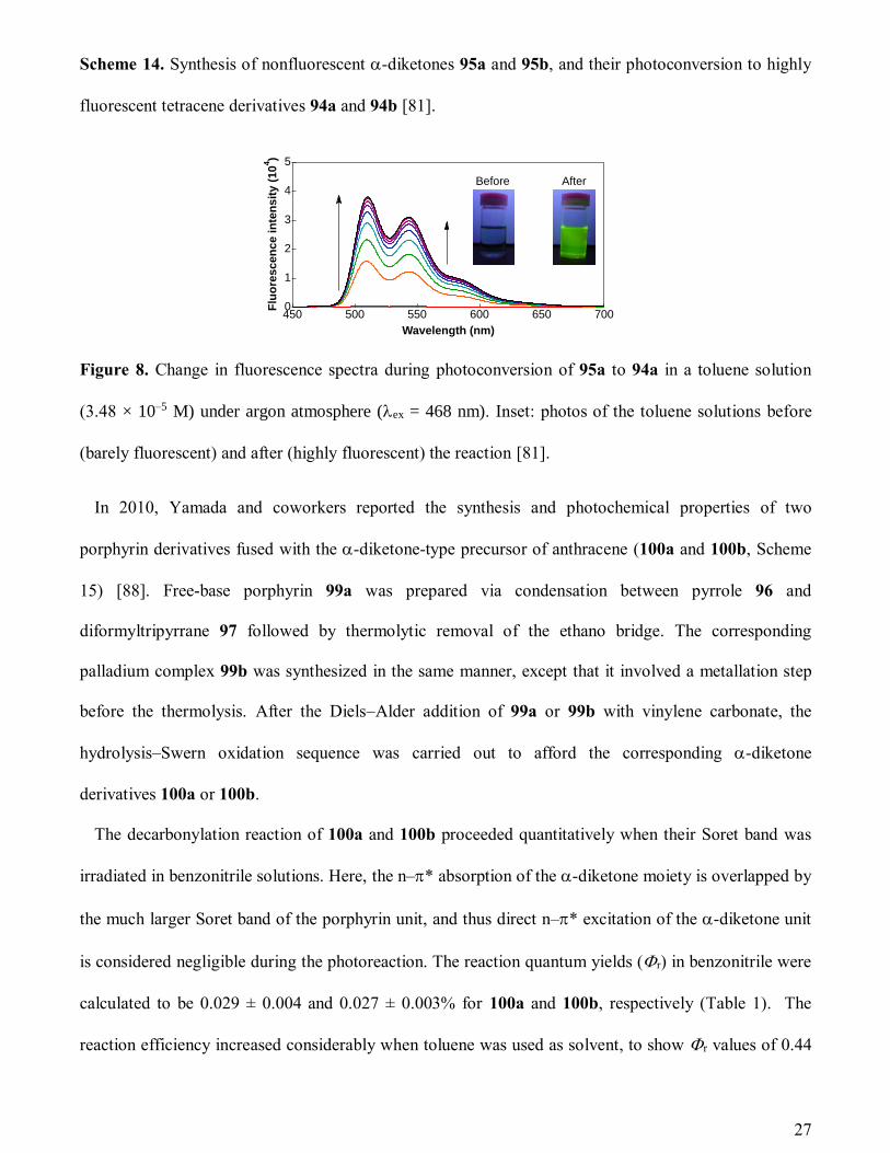
Figure 8. Change in fluorescence spectra during photoconversion of 95a to 94a in a toluene solution
(3.48 × 10⁻⁵ M) under argon atmosphere (ex = 468 nm). Inset: photos of the toluene solutions before
(barely fluorescent) and after (highly fluorescent) the reaction [81].
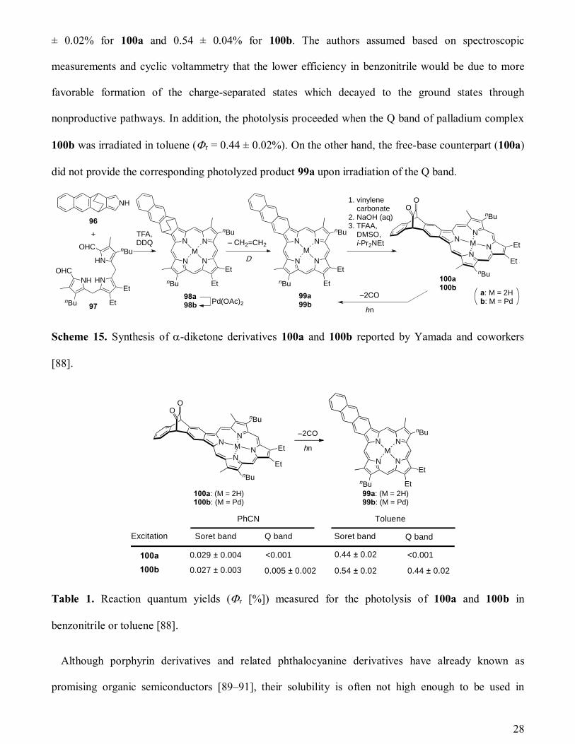
In 2010, Yamada and coworkers reported the synthesis and photochemical properties of two
porphyrin derivatives fused with the -diketone-type precursor of anthracene (100a and 100b, Scheme
15) [88]. Free-base porphyrin 99a was prepared via condensation between pyrrole 96 and
diformyltripyrrane 97 followed by thermolytic removal of the ethano bridge. The corresponding
palladium complex 99b was synthesized in the same manner, except that it involved a metallation step
before the thermolysis. After the Diels–Alder addition of 99a or 99b with vinylene carbonate, the
hydrolysis–Swern oxidation sequence was carried out to afford the corresponding -diketone
derivatives 100a or 100b.
The decarbonylation reaction of 100a and 100b proceeded quantitatively when their Soret band was
irradiated in benzonitrile solutions. Here, the n–* absorption of the -diketone moiety is overlapped by
the much larger Soret band of the porphyrin unit, and thus direct n–* excitation of the -diketone unit
is considered negligible during the photoreaction. The reaction quantum yields (r) in benzonitrile were
calculated to be 0.029 ± 0.004 and 0.027 ± 0.003% for 100a and 100b, respectively (Table 1). The
reaction efficiency increased considerably when toluene was used as solvent, to show r values of 0.44
5
4
3
2
1
0Flu
ore
sce
nc
e i
nte
ns
ity
(10
4)
700650600550500450
Wavelength (nm)
Before After
28
± 0.02% for 100a and 0.54 ± 0.04% for 100b. The authors assumed based on spectroscopic
measurements and cyclic voltammetry that the lower efficiency in benzonitrile would be due to more
favorable formation of the charge-separated states which decayed to the ground states through
nonproductive pathways. In addition, the photolysis proceeded when the Q band of palladium complex
100b was irradiated in toluene (r = 0.44 ± 0.02%). On the other hand, the free-base counterpart (100a)
did not provide the corresponding photolyzed product 99a upon irradiation of the Q band.
Scheme 15. Synthesis of -diketone derivatives 100a and 100b reported by Yamada and coworkers
[88].
Table 1. Reaction quantum yields (r [%]) measured for the photolysis of 100a and 100b in
benzonitrile or toluene [88].
Although porphyrin derivatives and related phthalocyanine derivatives have already known as
promising organic semiconductors [89–91], their solubility is often not high enough to be used in
NH
OHC
HN
OHC
HN
nBu Et
Et
nBu
NH
N
N N
N
nBu Et
Et
nBu
M
N
N N
N
nBu Et
Et
nBu
M
TFA,DDQ
96
97
98a98b
Pd(OAc)2
99a99b
100a100b
+
D
– CH2=CH2
1. vinylene carbonate2. NaOH (aq)3. TFAA, DMSO, i-Pr2NEt
hn
–2CO
OO
N
NN
NM
nBu
nBu
Et
Et
a: M = 2Hb: M = Pd
Excitation Soret band Soret bandQ band Q band
PhCN Toluene
100a
100b
0.029 ± 0.004
0.027 ± 0.003
<0.001 <0.001
0.005 ± 0.002
0.44 ± 0.02
0.54 ± 0.02 0.44 ± 0.02
100a: (M = 2H)100b: (M = Pd)
OO
N
NN
NM
nBu
nBu
Et
Et hn
–2CO
N
N N
N
nBu Et
Et
nBu
M
99a: (M = 2H)99b: (M = Pd)
29
solution processes. In this context, introducing the -diketone unit to already known, high performance
organic semiconductors is highly beneficial, because it endows organic semiconductors of interest with
higher solubility, thereby potentially allowing device fabrication based on solution techniques. Along
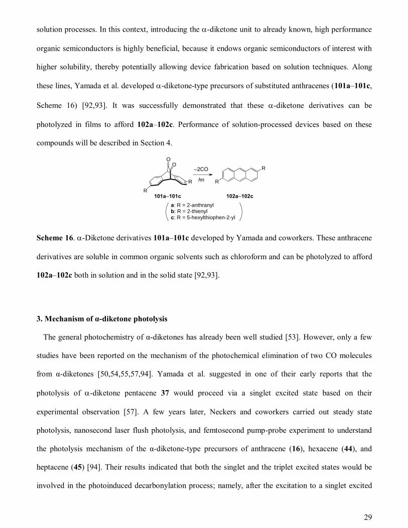
these lines, Yamada et al. developed -diketone-type precursors of substituted anthracenes (101a–101c,
Scheme 16) [92,93]. It was successfully demonstrated that these -diketone derivatives can be
photolyzed in films to afford 102a–102c. Performance of solution-processed devices based on these
compounds will be described in Section 4.
Scheme 16. -Diketone derivatives 101a–101c developed by Yamada and coworkers. These anthracene
derivatives are soluble in common organic solvents such as chloroform and can be photolyzed to afford
102a–102c both in solution and in the solid state [92,93].
3. Mechanism of α-diketone photolysis
The general photochemistry of α-diketones has already been well studied [53]. However, only a few
studies have been reported on the mechanism of the photochemical elimination of two CO molecules
from α-diketones [50,54,55,57,94]. Yamada et al. suggested in one of their early reports that the
photolysis of -diketone pentacene 37 would proceed via a singlet excited state based on their
experimental observation [57]. A few years later, Neckers and coworkers carried out steady state
photolysis, nanosecond laser flush photolysis, and femtosecond pump-probe experiment to understand
the photolysis mechanism of the α-diketone-type precursors of anthracene (16), hexacene (44), and
heptacene (45) [94]. Their results indicated that both the singlet and the triplet excited states would be
involved in the photoinduced decarbonylation process; namely, after the excitation to a singlet excited
OO
R
R
101a–101c
R
R
102a–102c
hn
–2CO
a: R = 2-anthranylb: R = 2-thienylc: R = 5-hexylthiophen-2-yl

30
state, the -diketones undergo vibrational relaxation and decarbonylation from the singlet manifold, or
alternatively they undergo vibrational relaxation, intersystem crossing, then decarbonylation from the
triplet manifold. They also speculated that most likely the bond between a carbonyl carbon and a
bridgehead carbon would break first to form a biradical species. However, they did not rule out the
alternative possibility in which the bond between the two carbonyl carbons dissociates first. Bettinger et
al. conducted a theoretical investigation on the photolysis mechanism of the anthracene precursor 16
based on the potential energy profiles for the ground (S0), first singlet excited (S1), and first triplet
excited (T1) states [54]. They carried out density functional theory (DFT) geometry optimizations, and
coupled-cluster (CCSD(T)) and second-order multireference perturbation theory (MRMP2) energy
estimations to map the energy profiles. These calculations indicated that the first step on the T1 surface
involves cleavage of the C–C bond between one of the bridgeheads and the neighboring carbonyl group
to yield a biradical intermediate, followed by the loss of two CO molecules to give triplet anthracene.
On the S1 surface, a conical intersection of the S1 surface with the S0 surface exists after the transition
state for the analogous C–C bond cleavage, which provides a means for relaxation to the biradical
intermediate on the S0 surface. From this intermediate, the concerted loss of two CO molecules can
occur through a reaction with only a small barrier.
In the followings of this section, we will describe our recent findings from quantum chemical
calculations where the photolysis paths via higher excited states were also taken into consideration. We
employed the benzene precursor (103, Scheme 17) as a model, which is the smallest α-diketone
derivative to give off an aromatic compound by decarbonylation. Here, our focus is on the singlet
excited state paths, and triplet paths will not be mentioned. The results indicate that the key excited
states in the photocleavage reaction are the 11B1 and 11B2 states. If the molecule is excited to the 11B1
state, it follows a path where two CO molecules dissociate directly through a barrierless relaxation,
although state crossing regions may need to be passed. If the molecule is excited to the 11B2 state, it first
becomes a biradical and then dissociates to benzene and ethylenedione that falls apart to two CO

31
molecules subsequently. The reaction on the 11B2 state needs a small activation energy of about 12
kcal/mol.
Scheme 17. (a) The model system employed in the present computational study on the mechanism of -
diketone photolysis. The starting material 103 gives off two carbon monoxide and one benzene
molecules upon photoirradiation. (b) -Diketone compound 104 studied by Rubin and Kapon [55].
3.1. Mechanism of benzene diketone photolysis
Let us first discuss the electronic structures of low-lying excited states of the α-diketone type benzene
precursor (103). The configuration interaction singles (CIS) method and time-dependent density
functional theory (TD-DFT) with the 6-31G(d) basis set were used for the calculations. Table 2 shows
the excitation energies for the S1 (11B2) and selected low-lying excited states with large oscillator
strength (the 21A1 and 11B1 states), while Figure 9 shows the restricted Hartree–Fock (RHF) molecular
orbitals (MOs) involved in the corresponding excitations. Note that the definitions of B1 and B2 are
opposite of those in the recent work by Bettinger et al. [54].
Table 2. Excitation energies, main configurations, and oscillator strengths of selected low-lying excited
states.
Method State Main configuration Excitation energy (eV) Oscillator strength
CIS/6-31G(d) S1(1B2) HOMO LUMO 3.92 0.0012
S4(1B1) HOMO LUMO+1 7.62 0.1379
S5(1A1) HOMO–1 LUMO 7.85 0.1455
TD-DFT/6-31G(d) S1(1B2) HOMO LUMO 2.67 0.0013
S3(1B1) HOMO LUMO+1 4.68 0.0099
S4(1A1) HOMO–1 LUMO 4.71 0.0559
OO
hn
–2CO
103
OO
104
(a) (b)
32
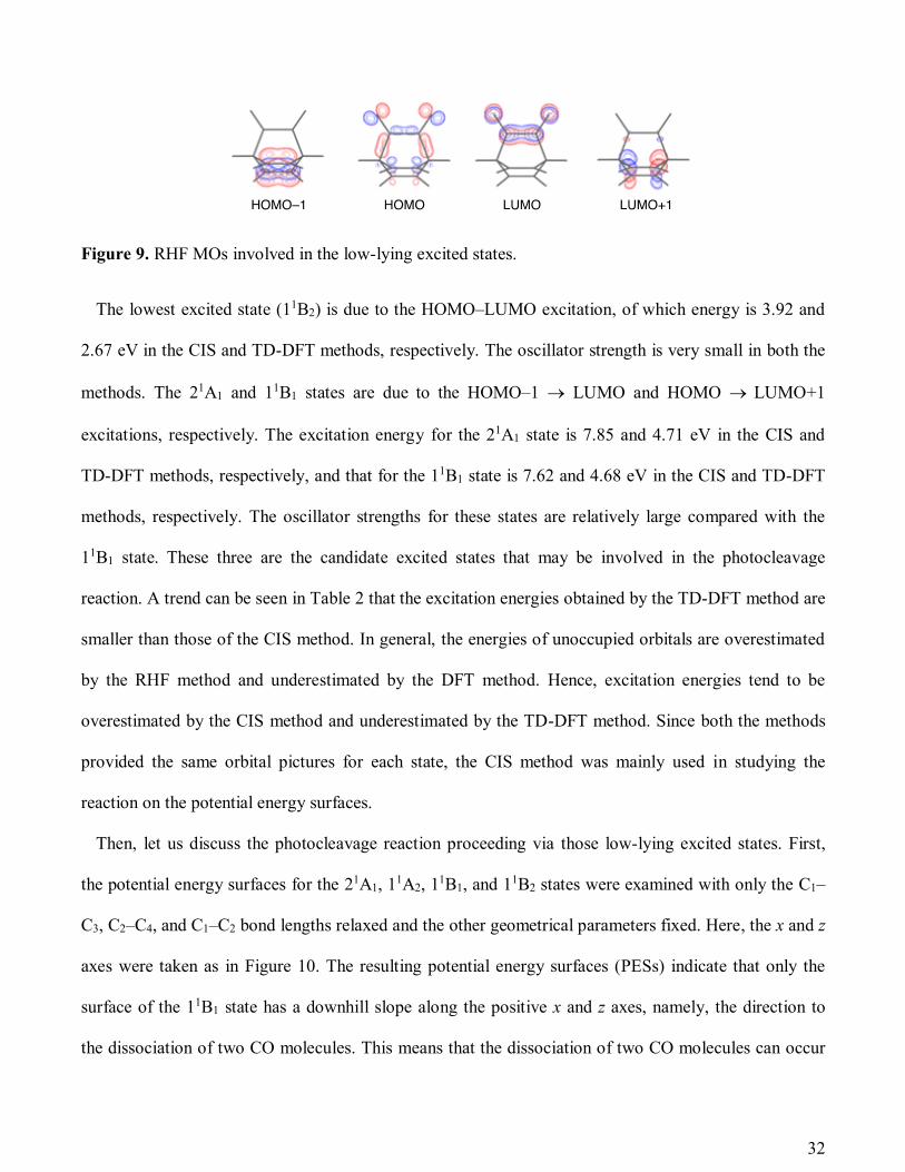
Figure 9. RHF MOs involved in the low-lying excited states.
The lowest excited state (11B2) is due to the HOMO–LUMO excitation, of which energy is 3.92 and
2.67 eV in the CIS and TD-DFT methods, respectively. The oscillator strength is very small in both the
methods. The 21A1 and 11B1 states are due to the HOMO–1 LUMO and HOMO LUMO+1
excitations, respectively. The excitation energy for the 21A1 state is 7.85 and 4.71 eV in the CIS and
TD-DFT methods, respectively, and that for the 11B1 state is 7.62 and 4.68 eV in the CIS and TD-DFT
methods, respectively. The oscillator strengths for these states are relatively large compared with the
11B1 state. These three are the candidate excited states that may be involved in the photocleavage
reaction. A trend can be seen in Table 2 that the excitation energies obtained by the TD-DFT method are
smaller than those of the CIS method. In general, the energies of unoccupied orbitals are overestimated
by the RHF method and underestimated by the DFT method. Hence, excitation energies tend to be
overestimated by the CIS method and underestimated by the TD-DFT method. Since both the methods
provided the same orbital pictures for each state, the CIS method was mainly used in studying the
reaction on the potential energy surfaces.
Then, let us discuss the photocleavage reaction proceeding via those low-lying excited states. First,
the potential energy surfaces for the 21A1, 11A2, 1
1B1, and 11B2 states were examined with only the C1–
C3, C2–C4, and C1–C2 bond lengths relaxed and the other geometrical parameters fixed. Here, the x and z
axes were taken as in Figure 10. The resulting potential energy surfaces (PESs) indicate that only the
surface of the 11B1 state has a downhill slope along the positive x and z axes, namely, the direction to
the dissociation of two CO molecules. This means that the dissociation of two CO molecules can occur
33
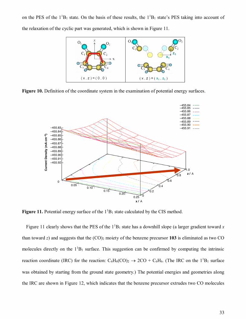
on the PES of the 11B1 state. On the basis of these results, the 11B1 state’s PES taking into account of
the relaxation of the cyclic part was generated, which is shown in Figure 11.
Figure 10. Definition of the coordinate system in the examination of potential energy surfaces.
Figure 11. Potential energy surface of the 11B1 state calculated by the CIS method.
Figure 11 clearly shows that the PES of the 11B1 state has a downhill slope (a larger gradient toward x
than toward z) and suggests that the (CO)2 moiety of the benzene precursor 103 is eliminated as two CO
molecules directly on the 11B1 surface. This suggestion can be confirmed by computing the intrinsic
reaction coordinate (IRC) for the reaction: C6H6(CO)2 2CO + C6H6. (The IRC on the 11B1 surface
was obtained by starting from the ground state geometry.) The potential energies and geometries along
the IRC are shown in Figure 12, which indicates that the benzene precursor extrudes two CO molecules
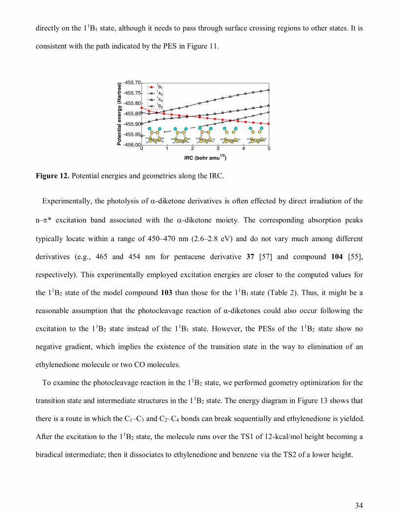
34
directly on the 11B1 state, although it needs to pass through surface crossing regions to other states. It is
consistent with the path indicated by the PES in Figure 11.
Figure 12. Potential energies and geometries along the IRC.
Experimentally, the photolysis of -diketone derivatives is often effected by direct irradiation of the
n–* excitation band associated with the -diketone moiety. The corresponding absorption peaks
typically locate within a range of 450–470 nm (2.6–2.8 eV) and do not vary much among different
derivatives (e.g., 465 and 454 nm for pentacene derivative 37 [57] and compound 104 [55],
respectively). This experimentally employed excitation energies are closer to the computed values for
the 11B2 state of the model compound 103 than those for the 11B1 state (Table 2). Thus, it might be a
reasonable assumption that the photocleavage reaction of α-diketones could also occur following the
excitation to the 11B2 state instead of the 11B1 state. However, the PESs of the 11B2 state show no
negative gradient, which implies the existence of the transition state in the way to elimination of an
ethylenedione molecule or two CO molecules.
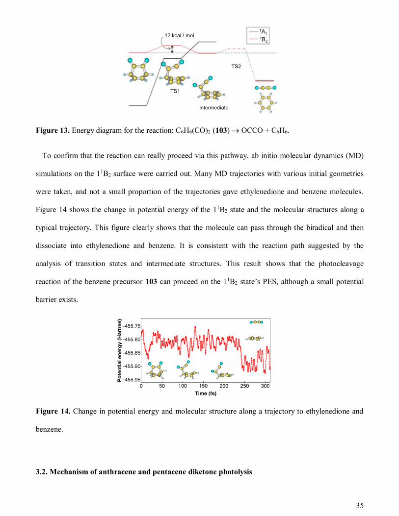
To examine the photocleavage reaction in the 11B2 state, we performed geometry optimization for the
transition state and intermediate structures in the 11B2 state. The energy diagram in Figure 13 shows that
there is a route in which the C1–C3 and C2–C4 bonds can break sequentially and ethylenedione is yielded.
After the excitation to the 11B2 state, the molecule runs over the TS1 of 12-kcal/mol height becoming a
biradical intermediate; then it dissociates to ethylenedione and benzene via the TS2 of a lower height.
35
Figure 13. Energy diagram for the reaction: C6H6(CO)2 (103) OCCO + C6H6.
To confirm that the reaction can really proceed via this pathway, ab initio molecular dynamics (MD)
simulations on the 11B2 surface were carried out. Many MD trajectories with various initial geometries
were taken, and not a small proportion of the trajectories gave ethylenedione and benzene molecules.
Figure 14 shows the change in potential energy of the 11B2 state and the molecular structures along a
typical trajectory. This figure clearly shows that the molecule can pass through the biradical and then
dissociate into ethylenedione and benzene. It is consistent with the reaction path suggested by the
analysis of transition states and intermediate structures. This result shows that the photocleavage
reaction of the benzene precursor 103 can proceed on the 11B2 state’s PES, although a small potential
barrier exists.
Figure 14. Change in potential energy and molecular structure along a trajectory to ethylenedione and
benzene.
3.2. Mechanism of anthracene and pentacene diketone photolysis

36
The PESs of the anthracene and pentacene precursors 16 and 37 were also surveyed using the same
methods. A feature different from the benzene precursor 103 is that the energy gaps between the excited
states are rather small compared with the benzene precursor. As a result, the PES topographies of 16 and
37 are more complicated than those for 103 because of the crossing and/or avoiding crossing to other
states. The results of the anthracene and pentacene precursors show that only the PESs of some 1B1
states have negative gradients both toward the z and x directions. This indicates that -diketones 16 and
37 can directly extrude two CO on the 1B1 states similarly to the case of 103. Although the experiments
imply the path through the 1B2 states, it has not been well clarified yet if there are dynamical paths in the
1B2 states for the anthracene and pentacene precursors.
3.3. Summary on the mechanism of -diketone photolysis
The benzene precursor 103 has two paths in the singlet states for the photocleavage reaction. One of
them is the path on the PES of 11B1 state. After the excitation to the 11B1 state, the molecule dissociates
directly into two CO molecules and benzene. The other is the path on the 11B2 state. The molecule in the
11B2 state passes through the biradical structure and then dissociates into ethylenedione and benzene.
This path has an activation barrier. It is also found for anthracene and pentacene precursors that after the
excitation to the 1B1 state the photocleavage reaction can proceed via the reaction paths similar to 103.
4. Device fabrication by the photoprecursor method
4.1. Film preparation
As described in Sections 1 and 2, -diketone-type precursors of acenes are generally more soluble and
stable than the corresponding acene compounds. By taking advantage of these features, it is possible to
fabricate acene-based thin-films via solution processes even when the acene compound of interest is not
compatible by itself with solution processes. Specifically, one can first deposit an -diketone-type
precursor of acene compound via a simple solution technique such as spin coating or drop casting, then

37
convert the precursor to the target acene compound within the film by photoirradiation under inert
atmosphere. Thus obtained thin-films can serve as active layers in organic (opto)electronic devices.
Ideally, the photoinduced reaction is quantitative without leaving any side products in the resulting film,
because the purity of the compound(s) in an active layer often has significant impact on device
performance.
The progress of photoconversion reaction within films can be monitored by UV–vis and infrared (IR)
spectroscopy. Figure 15 shows absorption spectra of the thin films prepared by spin-coating of
pentacene precursor 37 from a chloroform or o-dichlorobenzene (DCB) solution, either with or without
post-deposition photoirradiation to generate pentacene (1). For comparison, the spectrum of a vacuum-
deposited film of 1 is also presented. In the UV–vis spectra, the n–* absorption of -diketone moiety
at 470 nm disappears upon photoirradiation, while peaks characteristic of 1 emerge (compare traces a2
and a4 in Figure 15a). In the IR spectra, the C=O stretching peak around 1730 cm–1 disappears upon
photoirradiation (compare traces b1 and b3 in Figure 15b). It can be also seen in Figure 15 that the
progress of the photoconversion reaction strongly depends on the solvent used in the deposition process.
Precursor 37 can be fully converted in a film prepared from a solution in DCB (boiling point
180.5 °C)—After photoirradiation, the UV–vis spectrum of the film was very similar to that of the
vacuum-evaporated pentacene film (compare traces a4 and a5), and no C=O stretching was observed in
the IR spectrum (trace b3). In contrast, the absorption features associated with precursor 37 remained
after photoirradiation when the film was prepared from a solution in chloroform (boiling point 61.2 °C),
indicating that the conversion to 1 was incomplete in this case (traces a3 and b2). These observations
may be explained by an assumption that the higher boiling-point solvent (DCB) could maintain a
deposited film in a semidry state during the photoconversion reaction, allowing the molecules in the
film to easily reorganize so as to accommodate the structural change associated with the
decarbonylation reaction (i.e., from nonplanar 37 to planar 1). On the other hand, the lower boiling-
point solvent (chloroform) might have evaporated before the reaction completed, at which point further

38
conversion of the precursor was severely hampered because of the significantly smaller mobility
allowed for molecules without solvation.
Figure 15. (a) UV–vis spectra of thin films. (b) Attenuated total reflection-Fourier transform IR spectra
of thin films. Film preparation: a1 and b1, spin-coating 37 using chloroform; a2, spin-coating 37 using
DCB; a3 and b2, spin-coating 37 using chloroform then photoirradiation; a4 and b3, spin-coating 37
using DCB then photoirradiation; a5, pentacene was vacuum-evaporated [107].
Change in surface morphology during the photoconversion of a spin-coated film of 37 (from a
chlorobenzene solution) was observed by atomic force microscopy (AFM). As shown in Figure 16, the
film before photoirradiation exhibited a very smooth surface with no visible structures. Upon
photoirradiation, submicrometer-sized grains emerged in places over time, which eventually covered the
entire surface. This observation indicates that the as-spun film composes of randomly-oriented
molecules of 37, and the photoconversion to 1 induces local aggregation. The surface morphology of
pentacene films generated by the photoprecursor method is significantly different from that of vacuum
evaporated pentacene films having rigid dendrite structures [95]. This deviation in morphology was
presumed to originate from the different film formation processes; i.e., molecular diffusion on a
substrate with kinetic energy for the vacuum deposition versus molecular aggregation in a semidry state
for the photoprecursor method.

39
Figure 16. AFM images of a spin-coated film of photoprecursor 37 after various photoirradiation times.
The photoirradiation intensity was 200 mW cm–2. Chlorobenzene was used as solvent for spin-coating.
A different morphology resulted when a pentacene film was prepared by drop casting of a DCB
solution of precursor 37 [96]. Upon photoirradiation, a light-yellow dropped solution first turned red
indicating the formation of pentacene, then changed to purple associated with the precipitation of the
product 1. As shown in Figure 17, a thus prepared film composes of plate-like microcrystals having a
size of several microns. Here, the high boiling point (and thus slow evaporation rate) of DCB allowed
the photogenerated pentacene to crystallize from the solution phase to yield a highly crystalline film.
Figure 17 An optical microscope image of a pentacene film prepared by drop-casting of a DCB solution
of photoprecursor 37 followed by photoinduced conversion [96].
Crystallinity of the photogenerated pentacene films prepared by spin coating and drop casting were
investigated by X-ray diffractometry (XRD) in comparison with a vacuum-deposited pentacene film
(Figure 18). The vacuum-deposited film showed a strong and sharp peak at 5.72°(d = 15.5 Å) and

40
higher order diffraction peaks assigned to the (001) plane, indicating high crystallinity of the film and
perpendicular alignment of molecules to the substrate. The drop-cast film also showed strong diffraction
peaks, but at slightly higher diffraction angles (d = 14.4 Å). It is known that pentacene films exhibit
polymorphism with different d-spacing (d = 15.0–15.5 Å for the thin-film phase, d = 14.5 Å for the
bulk phase [97,98]. The thin-film phase has upright molecular orientation to the ab plane due to the
interaction with substrate during film formation, whereas the bulk phase has slightly inclined orientation
that is similar to the single-crystal structure. The XRD patterns indicate that the drop-cast film has the
bulk phase, whereas the evaporated and spin-coated films have the thin-film phase. In the in-plane XRD
measurements, the drop-cast film also indicated bulk phase diffraction peaks at lower angles (Figure
18b). Thus, the deposition process critically affects the resulting morphology of thin films prepared by
the photoprecursor method.
Figure 18. X-ray diffraction patterns of pentacene films prepared by direct vacuum evaporation of
pentacene (black) and by the photoprecursor method from spin-coated (red) or drop-cast (blue)
photoprecursor 37. Si/SiO2 substrates were used for all cases. (a) out-of-plane measurements, (b) in-
plane measurements [107].
4.2. Organic field-effect transistors
Organic field-effect transistors (OFETs) generally have a planar device structure composed of an
organic semiconductor film, a gate insulator, and three electrodes (gate, source and drain) as shown in

41
Figure 19. The output current between the source and drain electrode is modulated by the gate voltage.
OFETs require highly crystalline materials because the magnitude of output current is proportional to
the carrier mobility of semiconductor layer. Pentacene is a traditional benchmark material for p-type
OFETs, and its thin-film structure [95,97,98], electronic properties [99,100], and device performances
[101–103] have been extensively studied. Pentacene has a rigid and symmetric structure with a high
aspect ratio, giving highly crystalline films with the herringbone packing. In addition, vacuum-deposited
pentacene tends to align vertically on the hydrophobic surface [104]. This film structure is advantageous
to in-plane carrier transport, resulting in the high carrier mobility in OFET devices. Theoretical
calculation predicts a longer acene gives a higher carrier mobility [105], whereas its solubility becomes
lower. To obtain highly crystalline pentacene films by solution processes, several types of soluble
thermo-convertible precursors have been reported as shown in Figure 2 and Scheme 7. While some of
these thermo-precursors (i.e., monoketone-type derivatives in Scheme 7) can be converted also by light,
the -diketone-type precursors can be converted only by photoirradiation. This feature would be
advantageous in controlling the film structure using many parameters of light.
Figure 19. Schematic illustration of the device fabrication steps for bottom-gate/top-contact type
OFETs based on photogenerated organic semiconductors.
Bottom-gate and top-contact OFETs prepared by using -diketone pentacene 37 have been reported
[106,107]. The devices were fabricated by spin-coating a precursor solution on a pretreated substrate
and subsequent photoirradiation with a blue LED lamp (Figure 19). The source and drain gold
electrodes were then thermally evaporated. In order to achieve a fair balance between the thickness and
hn
(470 nm)

42
the crystallinity of resulting films, mixed solvent systems containing both low- and high-boiling point
solvents were employed in spin coating. Figure 20 shows typical modulation characteristics (output and
transfer characteristics) of the photogenerated pentacene films prepared from spin-coated 37.
Chloroform with 1% trichlorobenzene (TCB) gave the best performance in OFET devices. The film
structure and device performances were deeply affected by photoirradiation conditions. Since it is
important to finish photoconversion before the spin-coated film dries up, high intensity light was
suitable for obtaining higher mobility. In addition, elevated substrate temperature promoted
crystallization, even though the photoconversion reaction progresses at room temperature. The
optimized conditions (a light intensity of 300 mW cm–2, irradiation time for 60 min, and a substrate
temperature at 80 °C) yielded a carrier mobility as high as 0.86 cm2 V–1 s–1 [107]. This value is one of
the highest values obtained for spin-coated pentacene films, and comparable to those of vacuum-
evaporated ones. It should be noted that the high carrier mobility was observed in less crystalline
pentacene films showing no diffraction peaks. This anomaly may be explained by less effect of the
domain boundary. The photogenerated pentacene film composes of amorphous and crystalline regions,
and boundaries between crystalline domains are presumably filled by amorphous pentacene regions. As
a result, more carriers can be transported to the electrodes without being trapped at domain boundaries.
Figure 20. Typical modulation characteristics of the OFET devices based on photogenerated pentacene
films. (a) Output characteristics; (b) transfer characteristics [107].

43
In OFET materials, side alkyl chains are often employed to increase solubility and align the molecules
perpendicularly on a hydrophobic surface [108]. The effect of alkyl chains in photoconvertible materials
was investigated using anthracene diketone derivatives 101b and 101c (Scheme 16) [93]. The FET
mobilities in the thin films obtained from 101b and 101c were estimated to be 4.7 × 10⁻² and 2.6 × 10⁻⁴
cm2 V–1 s–1, respectively. Thus, the compound without alkyl chains (102b) showed higher mobility, and
this result may be explained by the different molecular arrangements observed by XRD measurements
of the resulting films (Figure 21). The film obtained from non-alkylated precursor 101b showed a
diffraction peak at 2 = 4.74° (d = 18.6 Å), which was assigned to the (100) plane, in the out-of-plane
measurement. This indicates that molecules of 102b aligned perpendicularly to the substrate, which is
advantageous for FET carrier mobility owing to large orbital overlapping in the current flow direction
[104]. In contrast, the film obtained from 101c exhibited a very weak diffraction peak corresponding to
the (011) plane in the out-of-plane measurement, indicating that molecules of 102c partially aligned
parallel to the substrate. Generally, alkyl chains in OFET materials are adsorbed on the hydrophobic
surface, and align side by side during spin-coating through the van der Waals interaction. However, this
type of arrangement is hardly observed for those thin films obtained by the photoprecursor method,
because spin-coated precursor films are mostly amorphous, and molecular rearrangement to have alkyl
chains anchored on the substrate is difficult in a solid-state film.

44
Figure 21. (a) XRD patterns of the thin films of 102b and 102c prepared from the corresponding
photoconvertible precursors 101b and 101c, respectively, on Si/SiO2 substrates (b) (100) and (011)
planes in single-crystal structure of 102c [93].
4.3. Organic photovoltaic cells
Organic photovoltaic (OPV) devices are based on the p–n junction similar to silicon solar cells [109],
where donor molecules work as p-type semiconductor and acceptor molecules work as n-type
semiconductor. Large acenes are promising materials also for photovoltaic devices due to their high
carrier mobility. Indeed, high performance OPV devices using pentacene [110,111] or tetracene [112]
with [60]fullerene (C60) as acceptor have been reported. These acene-based p–n heterojunction devices
have been mainly fabricated by vacuum deposition because of the low solubility of acenes.
Recently, pentacene films fabricated by the photoprecursor method were employed for photovoltaic
devices having the p–n heterojunction structure (Figure 22) [113]. The thin film of pentacene was
prepared by spin-coating the corresponding photoprecursor 37 and subsequent photoirradiation with a
blue LED lamp. An n-type layer of evaporated C60/Bathocuproine (BCP) with an Al cathode or spin-
coated PCBM with a Ca/Al cathode was prepared on top of the pentacene layer.
Figure 22. Schematic illustration of the device fabrication steps for p–n heterojunction OPV devices
comprising a pentacene layer prepared via the photoprecursor method.
hn
(470 nm)

45
Figure 23a shows J–V curves of the p–n junction device with evaporated C60 or spin-coated PCBM
under AM1.5G illumination with an intensity of 100 mW cm–2. Both devices exhibited the p–n diode
behavior and photovoltaic response. The device with evaporated C60 showed PCE of 0.47% (open
circuit voltage (VOC) of 0.26 V, short circuit current (JSC) of 3.42 mA cm–2, and fill factor (FF) of
52.1%). The device with spin-coated PCBM showed PCE of 0.38% (VOC = 0.47 V, JSC = 1.57 mA cm–2,
FF = 51.1%). The higher VOC of the PCBM device can be attributed to the higher LUMO level of
PCBM, because VOC proportionally correlates with the energy difference between the HOMO level of
donor and the LUMO level of acceptor [114,115]. The external quantum efficiency (EQE) spectra
(Figure 23b) indicate that both devices have sensitivity at the pentacene absorption band around 680 nm.
The JSC values of the devices having a photogenerated pentacene layer are lower compared to that of a
vacuum-deposited pentacene device with the configuration of ITO/pentacene/C60/BCP/Al (PCE =
1.00%, VOC = 0.32 V, JSC = 6.32 mA cm–2, FF = 49.8%). This difference is primary attributed to small
thickness of the photogenerated pentacene film. Indeed, the internal quantum efficiency (IQE) of the
photogenerated pentacene device was similar to that of the vacuum-deposited device (Figure 24),
indicating that the photoconverted pentacene film has equivalent potential to the vacuum-deposited film.
Figure 23. Photovoltaic performances of the p–n heterojunction devices composed of the
photogenerated pentacene, and the evaporated C60, or the spin-coated PCBM. (a) J–V curves under dark
condition and AM1.5G illumination. (b) External quantum efficiency (EQE) for monochromatic light.

46
Figure 24. UV–vis absorption and internal quantum efficiency (IQE) spectra for the p–n heterojunction
device composed of photogenerated or evaporated pentacene film and fullerene C60 [113].
5. Summary and concluding remarks
This review overviewed the development of -diketone-type precursors of acenes. -Diketone
derivatives are generally more soluble and thermally more stable than the corresponding acenes, and the
-diketone unit can be quantitatively removed by photoirradiation both in solution and in the solid state.
The so-far demonstrated utility of this class of acene precursors can be categorized into three main types.
The first is to provide convenient access to large or highly functionalized acenes which are otherwise
difficult, if not impossible, to synthesize. The synthesis of highly unstable nonacene from an -
diketone-type precursor should be highlighted in this context [64]. In the second type of cases, -
diketone derivatives are employed as photoresponsive switches to alter optoelectronic properties of
chromophores. Specifically, the -diketone moiety is introduced as a fluorescence-quenching unit to
form “masked” fluorophores, which can be “unmasked” upon photoirradiation via the photoinduced
decarbonylation to retrieve the original fluorescent nature [77,81]. Such systems may find use as
fluorescent molecular probes or in non-rewritable memory devices. In the third type of cases, -
diketone derivatives are used in the fabrication of acene-based organic devices by solution-based
deposition techniques. The use of photoconvertible precursors is highly beneficial when the original

47
acene compound is too insoluble or unstable to be directly employed in solution deposition. Importantly,
this photoprecursor method does not require high temperature, and thus would be compatible with
thermolabile substrates such as plastic. Successful application of this method to the fabrication of
organic transistors and solar cells has been demonstrated [93,106,113].
As can be seen by these examples, the usefulness of -diketone-type acene precursors was quickly
recognized by the scientific community during the last decade, and their use now extends well beyond
the synthesis of large acenes. For further development of this emerging class of compounds, deeper
understanding about photochemical properties and photoreaction mechanisms of a wider variety of
derivatives would be essential. We believe that combined efforts among synthetic, computational,
analytical, and engineering scientists would lead to effective use of photoconvertible acene precursors in
technologically relevant and cost effective ways. In this context, application of the photoprecursor
method to the fabrication of organic (opto)electronic devices is highly promising.
Acknowledgement
The authors thank Prof. Noboru Ono, Prof. Hidemitsu Uno, and Dr. Yuko Yamashita in Ehime
University, Dr. Daiki Kuzuhara, Dr. Shinya Ikeda, and Dr. Shuhei Katsuta in Nara Institute of Science
and Technology, Dr. Takao Motoyama and Ms. Chika Ohashi in Yamagata University, and many other
colleagues and students who collaborated with the authors in the project. This work was partly
supported by Grants-in-Aid for Scientific Research (No. 22350083 for HY and KN and 25288092 for
HY) and the Green Photonics Project in NAIST supported by MEXT, and by PRESTO, JST for HY and
KN.
References
[1] S.R. Forrest, Nature 428 (2004) 911–918.
[2] H. Sirringhaus, Adv. Mater. 17 (2005) 2411–2425.
[3] M. Helgesen, R. Søndergaard, F.C. Krebs, J. Mater. Chem. 20 (2010) 36–60.
[4] F.C. Krebs, S.A. Gevorgyan, J. Alstrup, J. Mater. Chem. 19 (2009) 5442–5451.
[5] W. Cai, X. Gong, Y. Cao, Sol. Energy Mater. Sol. Cells. 94 (2010) 114–127.
48
[6] Y. Li, Q. Guo, Z. Li, J. Pei, W. Tian, Energy Environ. Sci. 3 (2010) 1427–1436.
[7] A.J. Moulé, Curr. Opin. Solid State Mater. Sci. 14 (2010) 123–130.
[8] J. Xue, Polym. Rev. 50 (2010) 411–419.
[9] P.-L.T. Boudreault, A. Najari, M. Leclerc, Chem. Mater. 23 (2011) 456–469.
[10] B. Walker, C. Kim, T.-Q. Nguyen, Chem. Mater. 23 (2011) 470–482.
[11] C. Zhong, C. Duan, F. Huang, H. Wu, Y. Cao, Chem. Mater. 23 (2011) 326–340.
[12] X.-H. Zhu, J. Peng, Y. Cao, J. Roncali, Chem. Soc. Rev. 40 (2011) 3509–3524.
[13] S. Kola, J. Sinha, H.E. Katz, J. Polym. Sci. Part B Polym. Phys. 50 (2012) 1090–1120.
[14] X. Liu, Y.-Z. Long, L. Liao, X. Duan, Z. Fan, ACS Nano. 6 (2012) 1888–1900.
[15] A. Mishra, P. Bäuerle, Angew. Chem. Int. Ed. 51 (2012) 2020–2067.
[16] P.F. Moonen, I. Yakimets, J. Huskens, Adv. Mater. 24 (2012) 5526–5541.
[17] J.D. Myers, J. Xue, Polym. Rev. 52 (2012) 1–37.
[18] R. Po, C. Carbonera, A. Bernardi, F. Tinti, N. Camaioni, Sol. Energy Mater. Sol. Cells. 100
(2012) 97–114.
[19] Y. Yang, K. Mielczarek, M. Aryal, A. Zakhidov, W. Hu, ACS Nano. 6 (2012) 2877–2892.
[20] R.R. Søndergaard, M. Hösel, F.C. Krebs, J. Polym. Sci. Part B Polym. Phys. 51 (2013) 16–34.
[21] A. Facchetti, Nat. Mater. 12 (2013) 598–600.
[22] J.E. Anthony, Chem. Rev. 106 (2006) 5028–5048.
[23] J.E. Anthony, Angew. Chem. Int. Ed. 47 (2008) 452–483.
[24] D. Lehnherr, R.R. Tykwinski, Materials. 3 (2010) 2772–2800.
[25] R. Rieger, K. Müllen, J. Phys. Org. Chem. 23 (2010) 315–325.
[26] Y. Takeyama, S. Ono, Y. Matsumoto, Appl. Phys. Lett. 101 (2012) 083303–083303–4.
[27] S.S. Zade, M. Bendikov, J. Phys. Org. Chem. 25 (2012) 452–461.
[28] J.E. Anthony, J.S. Brooks, D.L. Eaton, S.R. Parkin, J. Am. Chem. Soc. 123 (2001) 9482–9483.
[29] Y. Diao, B.C.-K. Tee, G. Giri, J. Xu, D.H. Kim, H.A. Becerril, R.M. Stoltenberg, T.H. Lee, G.
Xue, S. C.B. Mannsfeld, Z. Bao, Nat. Mater. 12 (2013) 665–671.
[30] L. Han, P. Mandlik, K.H. Cherenack, S. Wagner, Appl. Phys. Lett. 94 (2009) 162105-1–162105-
3.
[31] M. Watanabe, K.-Y. Chen, Y.J. Chang, T.J. Chow, Acenes Generated from Precursors and Their
Semiconducting Properties, Acc. Chem. Res. 46 (2013) 1606–1615.
[32] A.R. Brown, A. Pomp, D.M. de Leeuw, D.B.M. Klaassen, E.E. Havinga, P. Herwig, K. Müllen, J.
Appl. Phys. 79 (1996) 2136–2138.
[33] A. Afzali, C.D. Dimitrakopoulos, T.L. Breen, J. Am. Chem. Soc. 124 (2002) 8812–8813.
[34] A. Afzali, C.D. Dimitrakopoulos, T.O. Graham, Adv. Mater. 15 (2003) 2066–2069.
[35] M.-J. Joung, J.-H. Ahn, S.-Y. Kang, K.-H. Baek, S.-D. Ahn, L.-M. Do, C.-A. Kim, G.-H. Kim, I.-
K. You, S.-M. Yoon, K.-S. Suh, Bull. Korean Chem. Soc. 24 (2003) 1862–1864.
[36] N. Vets, M. Smet, W. Dehaen, Tetrahedron Lett. 45 (2004) 7287–7289.
[37] K.P. Weidkamp, A. Afzali, R.M. Tromp, R.J. Hamers, J. Am. Chem. Soc. 126 (2004) 12740–
12741.
[38] H.-H. Huang, H.-H. Hsieh, C.-C. Wu, C.-C. Lin, P.-T. Chou, T.-H. Chuang, Y.-S. Wen, T.J.
Chow, Tetrahedron Lett. 49 (2008) 4494–4497.
[39] T.-H. Chao, M.-J. Chang, M. Watanabe, M.-H. Luo, Y.J. Chang, T.-C. Fang, K.-Y. Chen, T.J.
Chow, Chem. Commun. 48 (2012) 6148–6150.
[40] M. Watanabe, W.-T. Su, K.-Y. Chen, C.-T. Chien, T.-H. Chao, Y.J. Chang, S.-W. Lin, T.J. Chow,
Chem. Commun. 49 (2013) 2240–2242.
[41] K.-Y. Chen, H.-H. Hsieh, C.-C. Wu, J.-J. Hwang, T.J. Chow, Chem. Commun. (2007) 1065–
1067.
[42] T.-H. Chuang, H.-H. Hsieh, C.-K. Chen, C.-C. Wu, C.-C. Lin, P.-T. Chou, T.-H. Chao, T.J. Chow,
Org. Lett. 10 (2008) 2869–2872.
[43] M. Watanabe, T.-H. Chao, S.-W. Liu, C.-T. Chien, Y.J. Chang, C.-H. Yuan, K.-C. Huang, S.-H.
Chien, T. Shinmyozu, T.J. Chow, J. Mater. Chem. 21 (2011) 11317–11322.

49
[44] C.-T. Chien, C.-C. Lin, M. Watanabe, Y.-D. Lin, T.-H. Chao, T. Chiang, X.-H. Huang, Y.-S.
Wen, C.-H. Tu, C.-H. Sun, T.J. Chow, J. Mater. Chem. 22 (2012) 13070–13075.
[45] M. Watanabe, Y.J. Chang, S.-W. Liu, T.-H. Chao, K. Goto, M.M. Islam, C.-H. Yuan, Y.-T. Tao,
T. Shinmyozu, T.J. Chow, Nat. Chem. 4 (2012) 574–578.
[46] M. Watanabe, T.-H. Chao, C.-T. Chien, S.-W. Liu, Y.J. Chang, K.-Y. Chen, T.J. Chow,
Tetrahedron Lett. 53 (2012) 2284–2287.
[47] C.-T. Chien, T.-C. Chiang, M. Watanabe, T.-H. Chao, Y.J. Chang, Y.-D. Lin, H.-K. Lee, C.-H.
Tu, C.-H. Sun, T.J. Chow, Tetrahedron Lett. 54 (2013) 903–906.
[48] D. Bryce-Smith, A. Gilbert, Chem. Commun. Lond. (1968) 1319–1320.
[49] C.F.H. Allen, Chem. Rev. 37 (1945) 209–268.
[50] J. Strating, B. Zwanenburg, A. Wagenaar, A.C. Udding, Tetrahedron Lett. 10 (1969) 125–128.
[51] J.L. Pyle, A.A. Shaffer, J.S. Cantrell, J. Org. Chem. 46 (1981) 115–118.
[52] A. Thomas, G. Anilkumar, V. Nair, Tetrahedron 52 (1996) 2481–2488.
[53] M.B. Rubin, Recent photochemistry of α-diketones, in: Photochem. Org. Synth., Springer Berlin
Heidelberg, 1985: pp. 1–56.
[54] H.F. Bettinger, R. Mondal, M. Krasowska, D.C. Neckers, J. Org. Chem. 78 (2013) 1851–1857.
[55] M.B. Rubin, M. Kapon, J. Photochem. Photobiol. Chem. 124 (1999) 41–46.
[56] H. Uno, Y. Yamashita, M. Kikuchi, H. Watanabe, H. Yamada, T. Okujima, T. Ogawa, N. Ono,
Tetrahedron Lett. 46 (2005) 1981–1983.
[57] H. Yamada, Y. Yamashita, M. Kikuchi, H. Watanabe, T. Okujima, H. Uno, T. Ogawa, K. Ohara,
N. Ono, Chem. –Eur. J. 11 (2005) 6212–6220.
[58] T. Aotake, S. Ikeda, D. Kuzuhara, S. Mori, T. Okujima, H. Uno, H. Yamada, Eur. J. Org. Chem.
(2012) 1723–1729.
[59] Y. Kamura, I. Shirotani, H. Inokuchi, Y. Maruyama, Chem. Lett. 3 (1974) 627–630.
[60] R. Mondal, R.M. Adhikari, B.K. Shah, D.C. Neckers, Org. Lett. 9 (2007) 2505–2508.
[61] R. Mondal, C. Tönshoff, D. Khon, D.C. Neckers, H.F. Bettinger, J. Am. Chem. Soc. 131 (2009)
14281–14289.
[62] H.F. Bettinger, R. Mondal, D.C. Neckers, Chem. Commun. (2007) 5209–5211.
[63] R. Mondal, B.K. Shah, D.C. Neckers, J. Photochem. Photobiol. Chem. 192 (2007) 36–40.
[64] C. Tönshoff, H.F. Bettinger, Angew. Chem. Int. Ed. 49 (2010) 4125–4128.
[65] D.R. Maulding, B.G. Roberts, J. Org. Chem. 34 (1969) 1734–1736.
[66] C.F.H. Allen, A. Bell, J. Am. Chem. Soc. 64 (1942) 1253–1260.
[67] A. Mallouli, Y. Lepage, Synthesis. 1980 (1980) 689–689.
[68] T. Takahashi, M. Kitamura, B. Shen, K. Nakajima, J. Am. Chem. Soc. 122 (2000) 12876–12877.
[69] D.M. Bowles, J.E. Anthony, Org. Lett. 2 (2000) 85–87.
[70] T. Takahashi, S. Li, W. Huang, F. Kong, K. Nakajima, B. Shen, T. Ohe, K. Kanno, J. Org. Chem.
71 (2006) 7967–7977.
[71] M.T. Stone, H.L. Anderson, J. Org. Chem. 72 (2007) 9776–9778.
[72] Y. Zhao, R. Mondal, D.C. Neckers, J. Org. Chem. 73 (2008) 5506–5513.
[73] Y. Zhao, X. Cai, E. Danilov, G. Li, D.C. Neckers, Photochem. Photobiol. Sci. 8 (2009) 34–36.
[74] C.-H. Lin, K.-H. Lin, B. Pal, L.-D. Tsou, Chem. Commun. (2009) 803–805.
[75] S. Katsuta, H. Yamada, T. Okujima, H. Uno, Tetrahedron Lett. 51 (2010) 1397–1400.
[76] C. Tönshoff, H.F. Bettinger, Chem. –Eur. J. 18 (2012) 1789–1799.
[77] T. Aotake, H. Tanimoto, H. Hotta, D. Kuzuhara, T. Okujima, H. Uno, H. Yamada, Chem.
Commun. 49 (2013) 3661–3663.
[78] M. Baumgarten, L. Gherghel, J. Friedrich, M. Jurczok, W. Rettig, J. Phys. Chem. A 104 (2000)
1130–1140.
[79] W. Weigel, W. Rettig, M. Dekhtyar, C. Modrakowski, M. Beinhoff, A.D. Schlüter, J. Phys. Chem.
A 107 (2003) 5941–5947.
[80] S.-W. Yang, A. Elangovan, K.-C. Hwang, T.-I. Ho, J. Phys. Chem. B 109 (2005) 16628–16635.

50
[81] T. Aotake, Y. Yamashita, T. Okujima, N. Shirasawa, Y. Jo, S. Fujimori, H. Uno, N. Ono, H.
Yamada, Tetrahedron Lett. 54 (2013) 1790–1793.
[82] W.E. Moerner, J. Phys. Chem. B 106 (2002) 910–927.
[83] M. Vendrell, D. Zhai, J.C. Er, Y.-T. Chang, Chem. Rev. 112 (2012) 4391–4420.
[84] S. Kawata, Y. Kawata, Chem. Rev. 100 (2000) 1777–1788.
[85] M. Irie, T. Fukaminato, T. Sasaki, N. Tamai, T. Kawai, Nature 420 (2002) 759–760.
[86] E. Deniz, S. Sortino, F.M. Raymo, J. Phys. Chem. Lett. 1 (2010) 1690–1693.
[87] D.W. Pohl, W. Denk, M. Lanz, Appl. Phys. Lett. 44 (1984) 651–653.
[88] H. Yamada, D. Kuzuhara, K. Ohkubo, T. Takahashi, T. Okujima, H. Uno, N. Ono, S. Fukuzumi,
J. Mater. Chem. 20 (2010) 3011–3024.
[89] Karl Kadish, Kevin M. Smith (Eds.), The Porphyrin Handbook, Academic Press, Amsterdam,
2003.
[90] Z. Bao, A.J. Lovinger, A. Dodabalapur, Adv. Mater. 9 (1997) 42–44.
[91] J. Zhang, J. Wang, H. Wang, D. Yan, Appl. Phys. Lett. 84 (2004) 142–144.
[92] H. Yamada, E. Kawamura, S. Sakamoto, Y. Yamashita, T. Okujima, H. Uno, N. Ono,
Tetrahedron Lett. 47 (2006) 7501–7504.
[93] H. Yamada, C. Ohashi, T. Aotake, S. Katsuta, Y. Honsho, H. Kawano, T. Okujima, H. Uno, N.
Ono, S. Seki, K. Nakayama, Chem. Commun. 48 (2012) 11136–11138.
[94] R. Mondal, A.N. Okhrimenko, B.K. Shah, D.C. Neckers, J. Phys. Chem. B 112 (2008) 11–15.
[95] R. Ruiz, D. Choudhary, B. Nickel, T. Toccoli, K.-C. Chang, A.C. Mayer, P. Clancy, J.M. Blakely,
R.L. Headrick, S. Iannotta, G.G. Malliaras, Chem. Mater. 16 (2004) 4497–4508.
[96] C. Ohashi, H. Yamada, K. Nakayama, Mol. Cryst. Liq. Cryst. (2013) in press.
[97] C.C. Mattheus, G.A. de Wijs, R.A. de Groot, T.T.M. Palstra, J. Am. Chem. Soc. 125 (2003)
6323–6330.
[98] T. Kakudate, N. Yoshimoto, Y. Saito, Appl. Phys. Lett. 90 (2007) 081903-1–081903-3.
[99] K. Hummer, C. Ambrosch-Draxl, Phys. Rev. B 72 (2005) 205205.
[100] H. Kakuta, T. Hirahara, I. Matsuda, T. Nagao, S. Hasegawa, N. Ueno, K. Sakamoto, Phys. Rev.
Lett. 98 (2007) 247601.
[101] Y.-Y. Lin, D.J. Gundlach, S.F. Nelson, T.N. Jackson, IEEE Electron Device Lett. 18 (1997) 606–
608.
[102] C.D. Dimitrakopoulos, A.R. Brown, A. Pomp, J. Appl. Phys. 80 (1996) 2501–2508.
[103] J. Takeya, C. Goldmann, S. Haas, K.P. Pernstich, B. Ketterer, B. Batlogg, J. Appl. Phys. 94
(2003) 5800–5804.
[104] C.D. Dimitrakopoulos, P.R.L. Malenfant, Adv. Mater. 14 (2002) 99–117.
[105] W.-Q. Deng, W.A. Goddard, J. Phys. Chem. B 108 (2004) 8614–8621.
[106] A. Masumoto, Y. Yamashita, S. Go, T. Kikuchi, H. Yamada, T. Okujima, N. Ono, H. Uno, Jpn. J.
Appl. Phys. 48 (2009) 051505.
[107] K. Nakayama, C. Ohashi, Y. Oikawa, H. Motoyama, H. Yamada, J. Mater. Chem. C. (2013) in
press.
[108] M. Halik, H. Klauk, U. Zschieschang, G. Schmid, S. Ponomarenko, S. Kirchmeyer, W. Weber,
Adv. Mater. 15 (2003) 917–922.
[109] J. Janata, M. Josowicz, J. Solid State Electrochem. 13 (2009) 41–49.
[110] S. Yoo, B. Domercq, B. Kippelen, Appl. Phys. Lett. 85 (2004) 5427–5429.
[111] A.K. Pandey, J.-M. Nunzi, Appl. Phys. Lett. 89 (2006) 213506-1–213506-3.
[112] C.-W. Chu, Y. Shao, V. Shrotriya, Y. Yang, Appl. Phys. Lett. 86 (2005) 243506-1–213506-3.
[113] T. Motoyama, T. Kiyota, H. Yamada, K. Nakayama, Sol. Energy Mater. Sol. Cells. 114 (2013)
156–160.
[114] M.C. Scharber, D. Mühlbacher, M. Koppe, P. Denk, C. Waldauf, A.J. Heeger, C.J. Brabec, Adv.
Mater. 18 (2006) 789–794.
[115] B.P. Rand, D.P. Burk, S.R. Forrest, Phys. Rev. B 75 (2007) 115327-1–115327-11.

51
Vitae
Mitsuharu Suzuki received his B.Eng. (2000) and M.Eng. (2002) in industrial chemistry from Kyoto
University (Japan). After working in Mitsubishi Gas Chemical Company as a researcher, he moved to
the United States and received his Ph.D. (2011) in chemistry from University of California, Los Angeles.
He then worked as a postdoctoral fellow at the same institute and Lawrence Berkeley National
Laboratory, before joining Nara Institute of Science and Technology (Japan) as an assistant professor in
2013. His current research focuses on the development of solution-processable molecular materials for
organic electronics applications.
Tatsuya Aotake was born in 1987 in Kagawa, Japan. He received his M.Sc in 2011 from Ehime
University under the direction of Professor Hidemitsu Uno. Currently, he is a Ph.D. student in the
research group of Professor Hiroko Yamada at Nara Institute of Science and Technology. His research
interest is organic synthetic chemistry for photofunctional materials.
Yuji Yamaguchi received his M.Sc. degree in 2008 and his Ph.D. in 2013 from Yamagata University.
Now, He has been a JST-CREST Postdoctoral Research Fellow. His research interests include organic
synthesis, material science in organic transistors and organic photovoltaic device.

52
Nao Noguchi received her master’s degree in chemistry from Kyushu University in 2006. She then
joined Pfizer and moved to Takeda Pharmaceuticals in 2009, where she is now a research scientist.
Haruyuki Nakano received his Ph.D. in chemistry in 1993 working under the direction of Professor
Shigeki Kato at Kyoto University. He then joined the faculty of the University of Tokyo. In 2003, he
moved to Kyushu University at Fukuoka, where he is now Professor of Theoretical Chemistry. His
research interest includes the development of many-body electronic structure theory and its application
to problems of broad chemical interest.
Ken-ichi Nakayama received his B. S. degree in Applied Chemistry in 1995, and his Ph.D. in 2000,
from Osaka University (Japan) under the direction of Prof. Masaaki Yokoyama. He then became an
Assistant Professor at Osaka University, and started his research on organic devices. In 2006, he moved
to Yamagata University (Japan) as an Associate Professor, and he joined Prof. Junji Kido's group. He
was also appointed as a researcher of Japan Science and Technology Agency (JST) in PRESTO project
(2006-2010). His research interests include device engineering and material science in organic
transistors and organic photovoltaic devices.

53
Hiroko Yamada received her Ph.D. degree (Science) in 1992 from Kyoto University. Since 2008, she
is an associate professor at Ehime University, then moved to Nara Institute Science and Technology in
2011. She was promoted to a full professor at NAIST in 2012. From 2007 to 2010, she was a researcher
of PRESTO, Japan Science and Technology Agency (JST), and then a group leader of CREST project
(2010-2015), JST, on “Construction of organic thin-film solar cells with innovative solution-processible
organic materials”. Her current research focuses on the development of functional organic materials
including solution-processable molecular materials for organic electronics applications, large acenes and
porphyrinoid compounds.