Embed Size (px)
Citation preview
Lecture 13 - System design trends & challenges
Ari Kulmala, TUT, 2009
TKT-1212 Digitaalijärjestelmien toteutus
Acknowledgements
Ari Kulmala, TUT, 20082
The International Technology Roadmap for Semiconductors
M. Keating and P. Bricaud, “Reuse Methodology Manual for System-on-a-Chip Designs, 3rd Edition”
OutlineChallenges in digital systems
Hierarchical design in HDL
3 Ari Kulmala, TUT, 2008
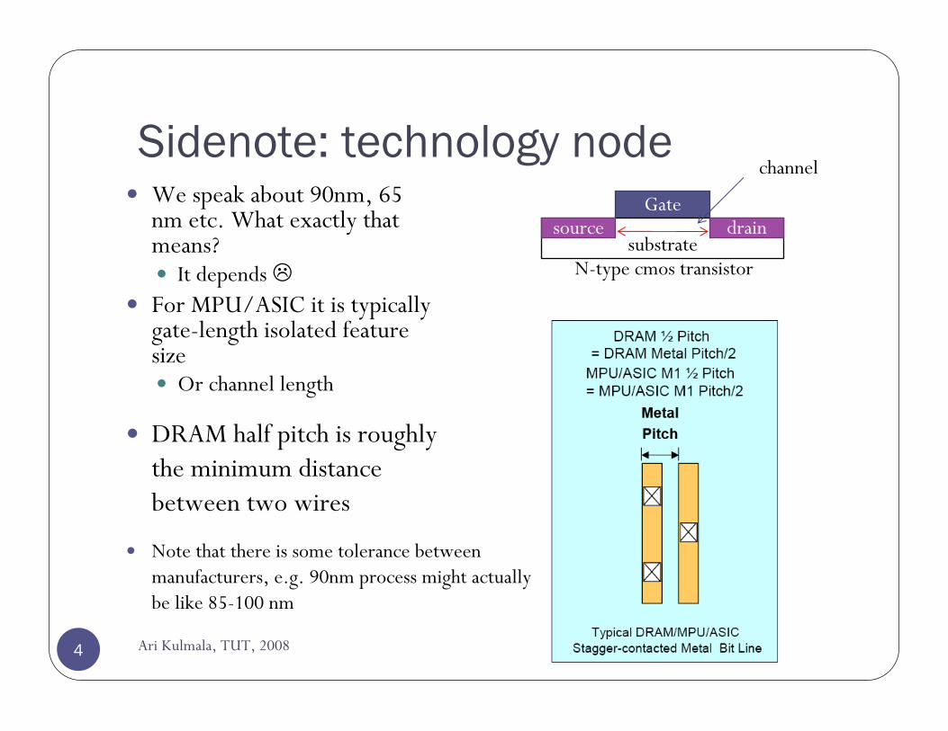
Sidenote: technology nodeWe speak about 90nm, 65 nm etc. What exactly that means?
It depends For MPU/ASIC it is typically gate-length isolated feature size
Or channel length
DRAM half pitch is roughly the minimum distance between two wires
Gate
substratesource drain
Note that there is some tolerance between manufacturers, e.g. 90nm process might actually be like 85-100 nm
N-type cmos transistor
channel
4 Ari Kulmala, TUT, 2008
Challenges in digital system designHigh-level challenges, not taking into account physical and manufacturing issues
1. Design complexity
2. Power consumption
3. Verification
4. (Chip area & performance)
5 Ari Kulmala, TUT, 2008
Design complexity85% of IC projects miss their original schedules
Average slip is 44%
http://eetimes.eu/semi/showArticle.jhtml?articleID=204702114&printable=true
One problem is that re-usable components are not, after all, easy to integrate
6 Ari Kulmala, TUT, 2008
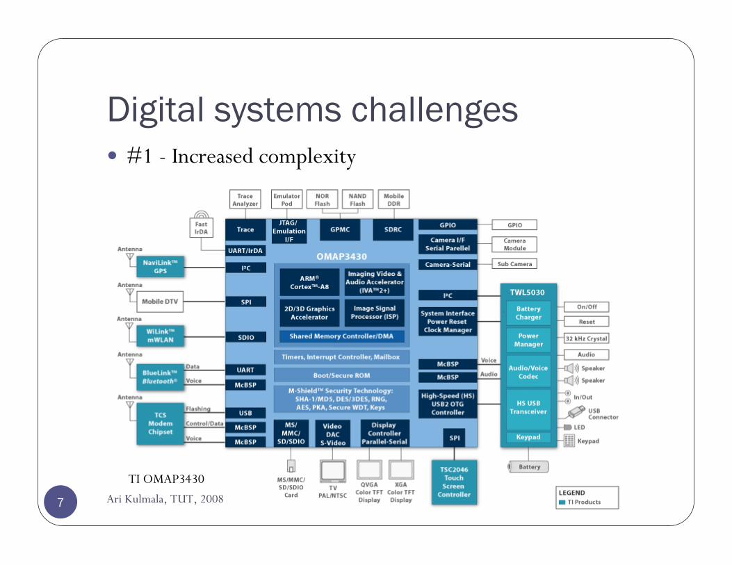
Digital systems challenges#1 - Increased complexity
TI OMAP3430
7 Ari Kulmala, TUT, 2008
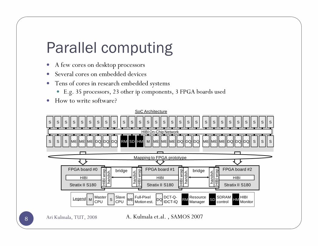
Parallel computingA few cores on desktop processorsSeveral cores on embedded devicesTens of cores in research embedded systems
E.g. 35 processors, 23 other ip components, 3 FPGA boards usedHow to write software?
ME
SS
RM SD HM M
SS SS SS SS
ME ME DQ DQDQ
S
DQ S SME ME
SS SS SS SS
ME DQ DQ DQ
S
SS S ME ME
SS SS SS SS
ME DQ DQS
HIBI On-Chip Network
FPGA board #0
Stratix II S180
FPGA board #1
Stratix II S180
HIBIHIBI
FPGA board #2
Stratix II S180
HIBI
SoC Architecture
SM RMME DQ SDMasterCPU
SlaveCPU
ResourceManager
Full-PixelMotion est.
DCT-Q-IDCT-IQ
SDRAMcontrol
Legend HM HIBI Monitor
Mapping to FPGA prototype
bridge bridge
hand
sh.
hand
sh.
HIB
I wra
p.
HIB
I wra
p.
HIB
I wra
p.
HIB
I wra
p.
hand
sh.
hand
sh.
A. Kulmala et.al. , SAMOS 20078 Ari Kulmala, TUT, 2008
System-on-chip (SoC)Purely:
Integrating whole system on a single chipChip complexity increasesProcessors, memories, hardware accelerators, I/Os, analog RF, …
LooselyA highly complex chip full of digital logicInterfaces to external memories, analog devices, etc
Two main types: power-efficient (PE) and high-performance (HP, later a.k.a. CS)
Target is to reduce cost1990-1992 mobile phones included 15 ICs and 800 other discrete components and in 2002 3-4 ICs and 200 discrete components
Cellular phones as embedded systems. Neuvo, Y. s.l. : IEEE International Solid-State Circuits Conference,Digest of Technical Papers, 2004. pp. 32-37.
9 Ari Kulmala, TUT, 2008
Power-efficient SoCs (SOC-PE)Its typical application area is electronic equipment categorized as “Mobile Consumer Platforms’”
this application area will make rapid progress in the foreseeable future across semiconductor technology generations.
Very high performance required while the power consumption is strictly limited by the battery (lifetime).
Advanced power consumption reduction techniquesAs a result, the requirement for processing power will be 1000× in the next ten years, while the requirement for dynamic power consumption will not change noticeably. The life cycle of “Mobile Consumer Platform” products is short, and will stay short in the future
The design effort cannot be increased—it needs to stay at the current level for the foreseeable future.
Die-size of around 64 mm2
ITRS 2005, http://www.itrs.net/Links/2005ITRS/SysDrivers2005.pdf10 Ari Kulmala, TUT, 2008
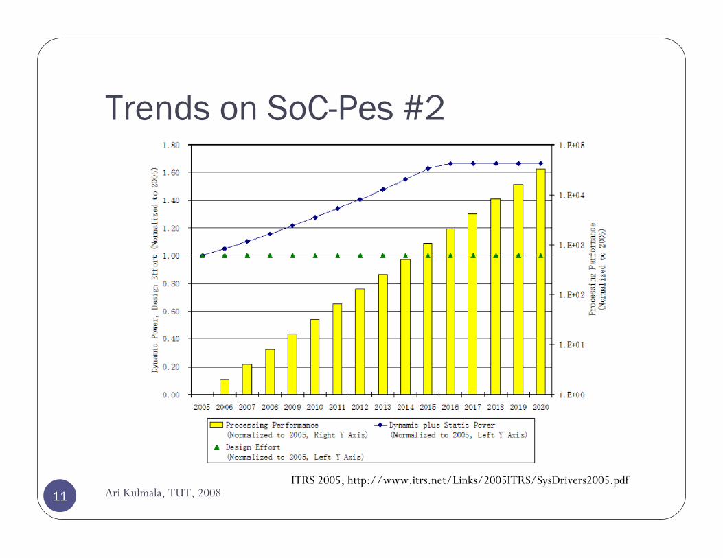
Trends on SoC-Pes #2
ITRS 2005, http://www.itrs.net/Links/2005ITRS/SysDrivers2005.pdf11 Ari Kulmala, TUT, 2008
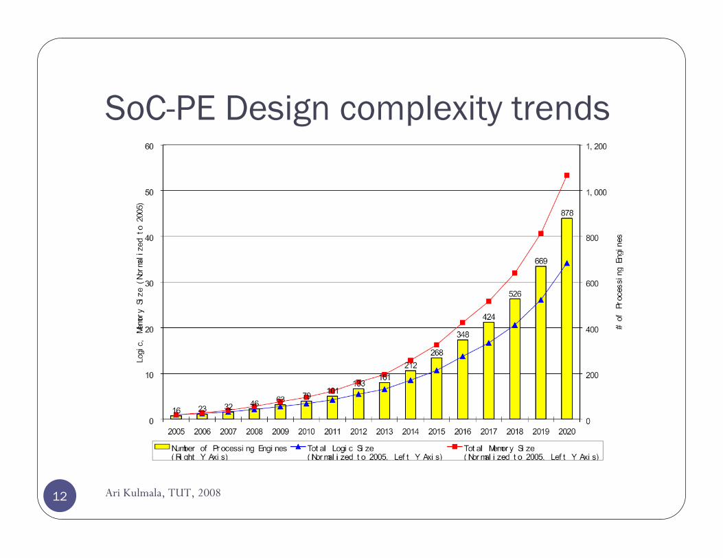
SoC-PE Design complexity trends
12 Ari Kulmala, TUT, 2008
SoC Consumer Stationary (SoC-CS)E.g. a high-end game machine (like PS3)Processing performance is most important differentiator. Required processing performance in year 2020 will be more than 70 TFLOPS.As Functions will be implemented and realized mainly by software, high processing power is required, and hence this SOC needs many dataprocessing engine( DPE ). Comparing with the SOC-PE, has lower performance-per-power than SoC-PE, but better than in terms of functional flexibility in case of adding or modifying functions. The life cycle of those SOC-CS is relatively long, because it is easy to add or modify functions, and as a result the application area is wide. Less processing engines than in SoC-PE but the beasts are mightier in SoC-CSDie-size of around 220 mm2
13 Ari Kulmala, TUT, 2008
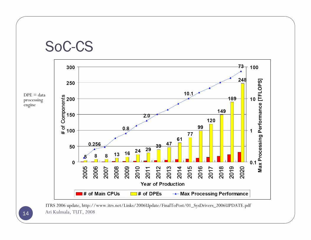
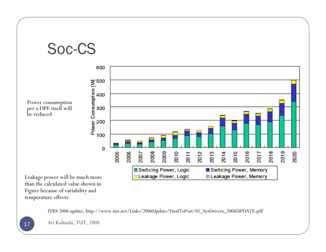
SoC-CS
ITRS 2006 update, http://www.itrs.net/Links/2006Update/FinalToPost/01_SysDrivers_2006UPDATE.pdf
DPE = data processing engine
14 Ari Kulmala, TUT, 2008

Power consumption
15
Chip power consumption can be defined asPavg = Pdynamic + Pshort + Pleakage + Pstatic
Traditional view of CMOS transistors is that they do not consumepower while static (Pstatic)
However, in 90nm and below, leakage becomes an increasingly important factor (Pleakage)
A large proportion of power is consumed by dynamic operations and switching (next slide)Pshort = short-circuit power, e.g. when gate switches state, both transistor types are conducting at the same time for some time
~10% of total chip power
Benini: dynamic power managementAri Kulmala, TUT, 2008
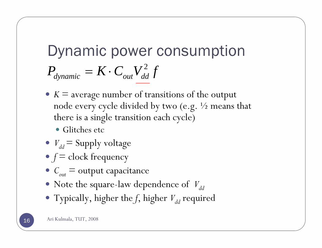
Dynamic power consumption
16
K = average number of transitions of the output node every cycle divided by two (e.g. ½ means that there is a single transition each cycle)
Glitches etc
Vdd = Supply voltagef = clock frequencyCout = output capacitanceNote the square-law dependence of Vdd
Typically, higher the f, higher Vdd required
2dynamic out ddP K C V f= ⋅
Ari Kulmala, TUT, 2008
Soc-CS
ITRS 2006 update, http://www.itrs.net/Links/2006Update/FinalToPost/01_SysDrivers_2006UPDATE.pdf
Leakage power will be much more than the calculated value shown in Figure because of variability and temperature effects
Power consumption per a DPE itself will be reduced
17 Ari Kulmala, TUT, 2008
SOC-CS POWER CONSUMPTION TRENDS
Different from the SOC-PE, the SOC-CS is generally free from the battery life issue, however rapid power consumption growth has a critical impact on chip packaging issue and cooling issue.
Leakage power will be much more than the calculated value shown in last slide because of variability and temperature effects.
Power consumption per a DPE itself will be reduced because the decreasing factor such as Vdd and insulator dielectric constant become dominant.
18 Ari Kulmala, TUT, 2008
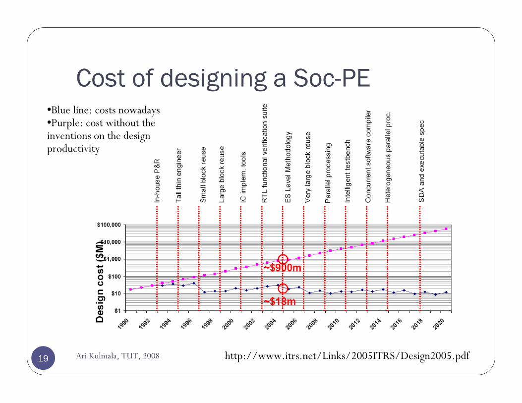
Cost of designing a Soc-PE•Blue line: costs nowadays•Purple: cost without the inventions on the design productivity
http://www.itrs.net/Links/2005ITRS/Design2005.pdf19 Ari Kulmala, TUT, 2008
20 Ari Kulmala, TUT, 2008
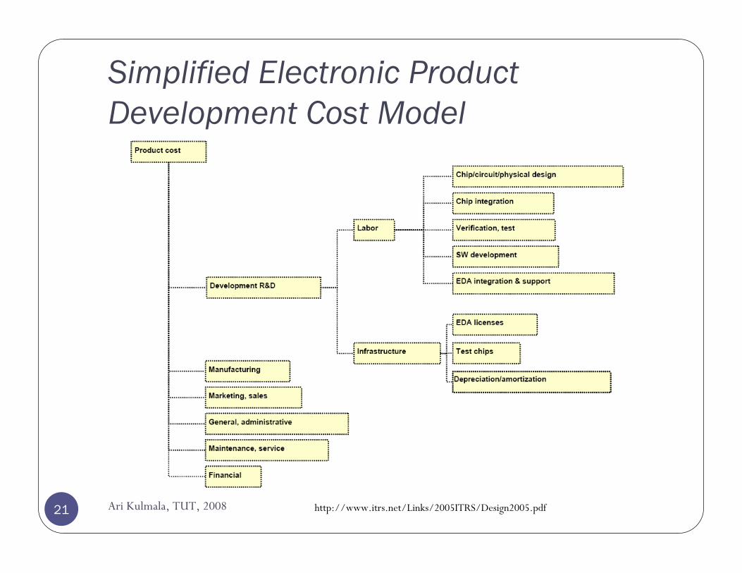
Simplified Electronic Product Development Cost Model
http://www.itrs.net/Links/2005ITRS/Design2005.pdf21 Ari Kulmala, TUT, 2008
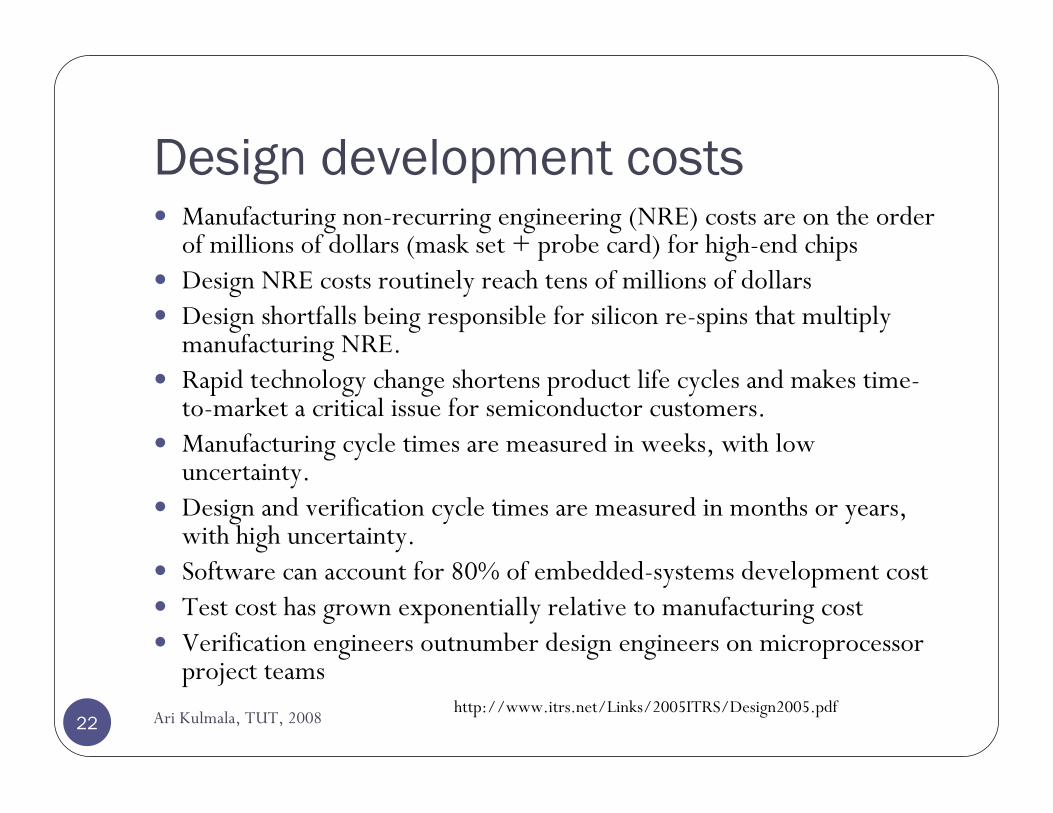
Design development costsManufacturing non-recurring engineering (NRE) costs are on the order of millions of dollars (mask set + probe card) for high-end chipsDesign NRE costs routinely reach tens of millions of dollarsDesign shortfalls being responsible for silicon re-spins that multiply manufacturing NRE. Rapid technology change shortens product life cycles and makes time-to-market a critical issue for semiconductor customers. Manufacturing cycle times are measured in weeks, with low uncertainty. Design and verification cycle times are measured in months or years, with high uncertainty. Software can account for 80% of embedded-systems development costTest cost has grown exponentially relative to manufacturing costVerification engineers outnumber design engineers on microprocessor project teams
http://www.itrs.net/Links/2005ITRS/Design2005.pdf22 Ari Kulmala, TUT, 2008
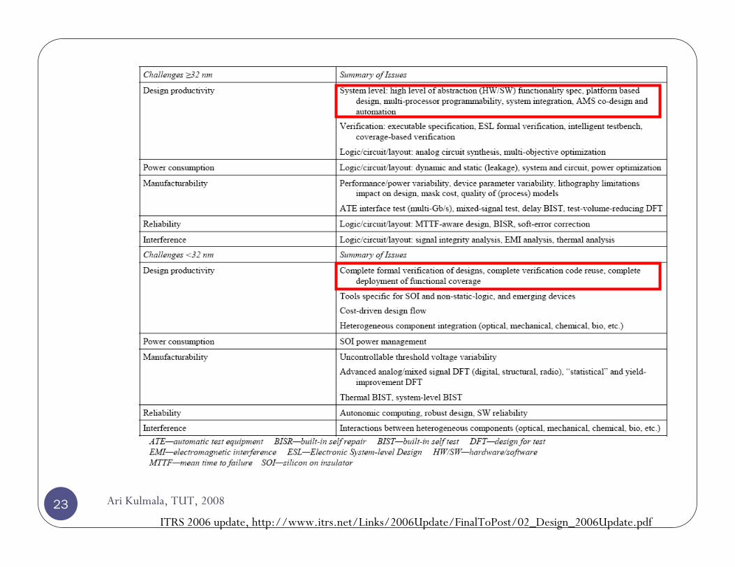
ITRS 2006 update, http://www.itrs.net/Links/2006Update/FinalToPost/02_Design_2006Update.pdf23 Ari Kulmala, TUT, 2008

http
://w
ww
.itrs
.net
/Lin
ks/2
005I
TR
S/Sy
sDri
vers
2005
24 Ari Kulmala, TUT, 2008
Courtesy of Erno Salminen
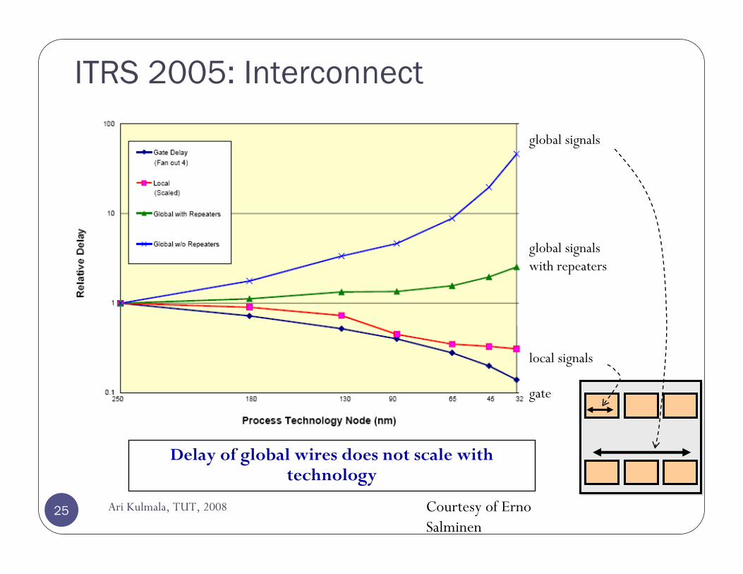
ITRS 2005: Interconnect
Delay of global wires does not scale with technology
gate
local signals
global signals with repeaters
global signals
25 Ari Kulmala, TUT, 2008
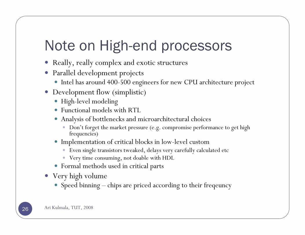
Note on High-end processorsReally, really complex and exotic structuresParallel development projects
Intel has around 400-500 engineers for new CPU architecture projectDevelopment flow (simplistic)
High-level modelingFunctional models with RTLAnalysis of bottlenecks and microarchitectural choices
Don’t forget the market pressure (e.g. compromise performance to get high frequencies)
Implementation of critical blocks in low-level customEven single transistors tweaked, delays very carefully calculated etcVery time consuming, not doable with HDL
Formal methods used in critical partsVery high volume
Speed binning – chips are priced according to their freqeuncy
26 Ari Kulmala, TUT, 2008
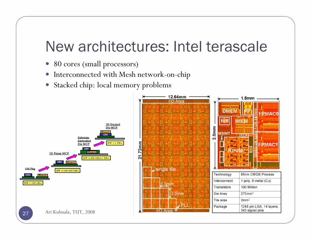
New architectures: Intel terascale
Ari Kulmala, TUT, 200827
80 cores (small processors)Interconnected with Mesh network-on-chipStacked chip: local memory problems
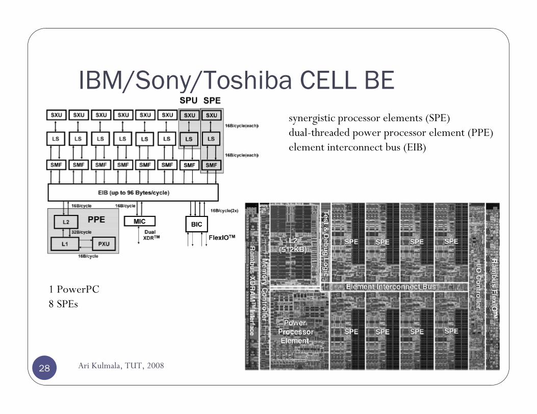
IBM/Sony/Toshiba CELL BE
Ari Kulmala, TUT, 200828
synergistic processor elements (SPE)dual-threaded power processor element (PPE)element interconnect bus (EIB)
1 PowerPC8 SPEs
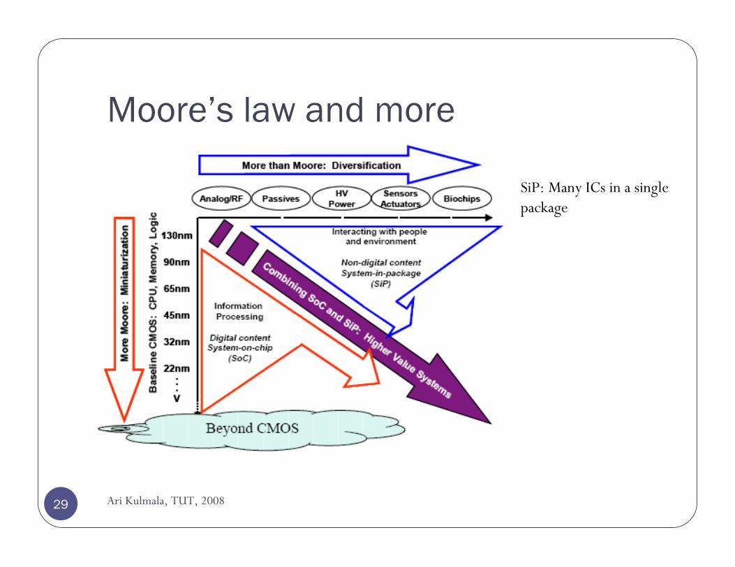
Moore’s law and more
Ari Kulmala, TUT, 200829
SiP: Many ICs in a single package
Teaching in DCS
Ari Kulmala, TUT, 200830
DI-tutkinto 30 opDI-tutkinto 30 opesitiedot esitiedot kandidaatin tutkinto 25 opkandidaatin tutkinto 25 op
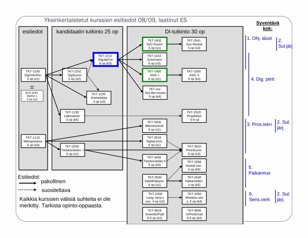
Yksinkertaistetut kurssien esitiedot 08/09, laatinut ES
TKT-1100 DigTeknPer.
3 op (s1)
TKT-1100 DigTeknPer.
3 op (s1)
TKT-1202 DigSuunn5 op (s2)
TKT-1202 DigSuunn5 op (s2)
TKT-1212 DigJärjTot8 op (k3)
TKT-1212 DigJärjTot8 op (k3)
TKT-1220 Aritmetiikka
4 op (s3)
TKT-1220 Aritmetiikka
4 op (s3)
TKT-3200 Tietokonetekn. I
5 op (s1)
TKT-3200 Tietokonetekn. I
5 op (s1)
TKT-1110 Mikroprosess.
5 op (s3)
TKT-1110 Mikroprosess.
5 op (s3)
TKT-2431 SoC-Suunn
5 op (s1)
TKT-2431 SoC-Suunn
5 op (s1)
TKT-1230 Laboratorio
3 op (k5)
TKT-1230 Laboratorio
3 op (k5)
TKT-3400 Tietokonetekn II
5 op (k4)
TKT-3400 Tietokonetekn II
5 op (k4)
TKT-1400 ASIC I
5 op (s1)
TKT-1400 ASIC I
5 op (s1)
TKT-1410 SunnVarm5 op (s3)
TKT-1410 SunnVarm5 op (s3)
TKT-3541 Soc-Alustat
5 op (s3)
TKT-3541 Soc-Alustat
5 op (s3)
TKT-1500 ASIC II
5 op (k4)
TKT-1500 ASIC II
5 op (k4)
TKT-3516 Signal proc.
5 op (s1)
TKT-3516 Signal proc.
5 op (s1)
TKT-3500 MIkrokontroll.
5 op (s1)
TKT-3500 MIkrokontroll.
5 op (s1)
TKT-3520ProsSuunn
5 op (s3)
TKT-3520ProsSuunn
5 op (s3)
TKT-2520 Projektityö
5-8 op
TKT-2520 Projektityö
5-8 op
TKT-2530SatellPaikann
5 op (s1)
TKT-2530SatellPaikann
5 op (s1)
TKT-9616ScientificPubl
4-5 op (s1)
TKT-9616ScientificPubl
4-5 op (s1)
TKT-2540PaikannMen
3 op (k5)
TKT-2540PaikannMen
3 op (k5)
TKT-9606OrPostGrad4-5 op (k4)
TKT-9606OrPostGrad4-5 op (k4)
ELE-1010 ElePer 13 op (s1)
ELE-1010 ElePer 13 op (s1)
=
pakollinensuositeltava
Kaikkia kurssien välisiä suhteita ei ole merkitty. Tarkista opinto-oppaasta.
1. Ohj. alust
4. Dig. piirit
3. Pros.tekn
5. Paikannus
TKT-2556Inertial nav.
5 op (k5)
TKT-2556Inertial nav.
5 op (k5)
TKT-2300 Lang. sens.v sov. 4 op (s2)
TKT-2300 Lang. sens.v sov. 4 op (s2)
TKT-2450 Wireless.sens. 5 op (k4)
TKT-2450 Wireless.sens. 5 op (k4)
6. Sens.verk
Syventäväkok:
2. Sul.järj
2. Sul. järj.
2. Sul. järj.
TKT-xxx Sys.des.issues
5 op (k4)
TKT-xxx Sys.des.issues
5 op (k4)
Esitiedot:
System design process
32 Ari Kulmala, TUT, 2008
Ari Kulmala, TUT, 200833
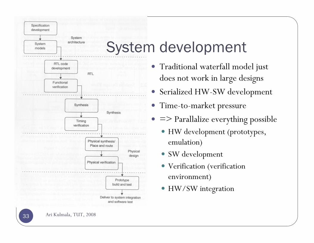
Traditional waterfall model just does not work in large designs
Serialized HW-SW development
Time-to-market pressure
=> Parallalize everything possibleHW development (prototypes, emulation)SW developmentVerification (verification environment)HW/SW integration
System development
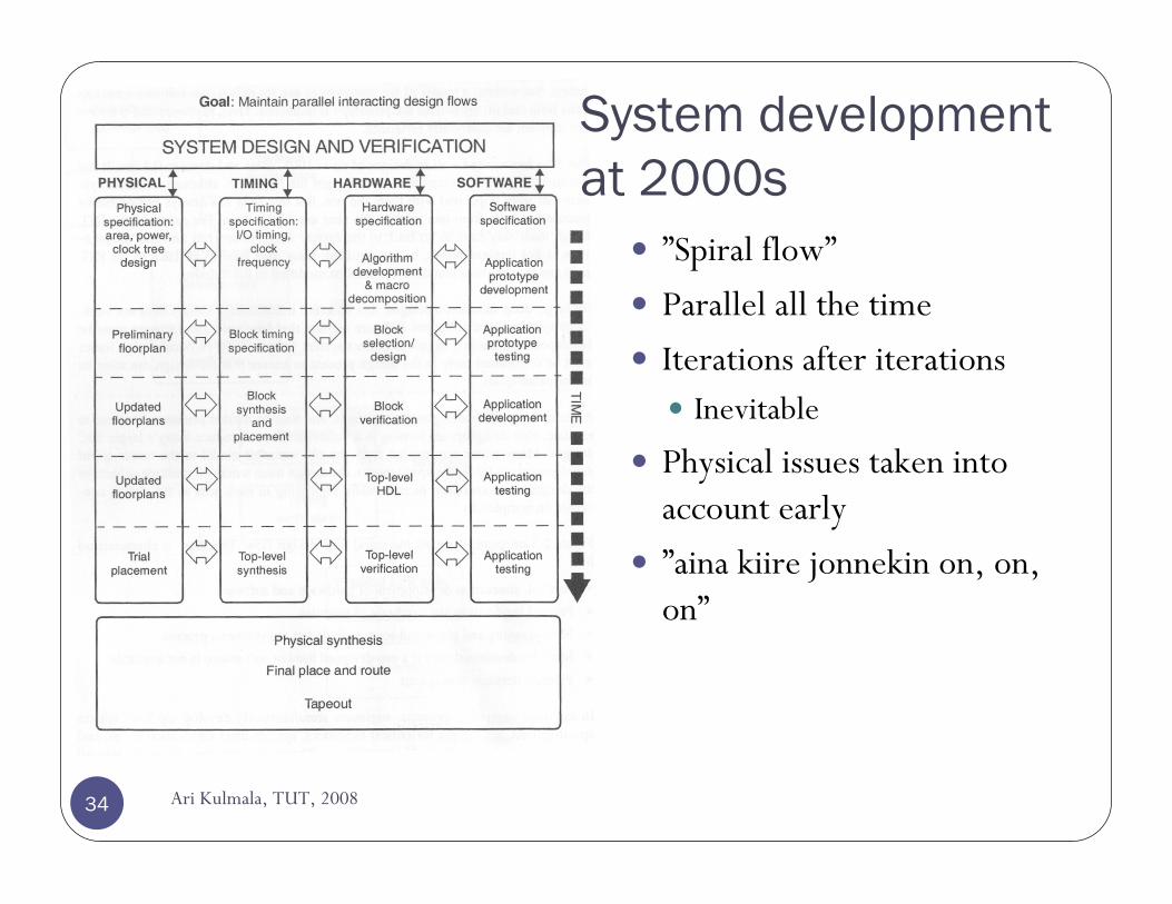
System development at 2000s
Ari Kulmala, TUT, 200834
”Spiral flow”
Parallel all the time
Iterations after iterationsInevitable
Physical issues taken into account early
”aina kiire jonnekin on, on, on”
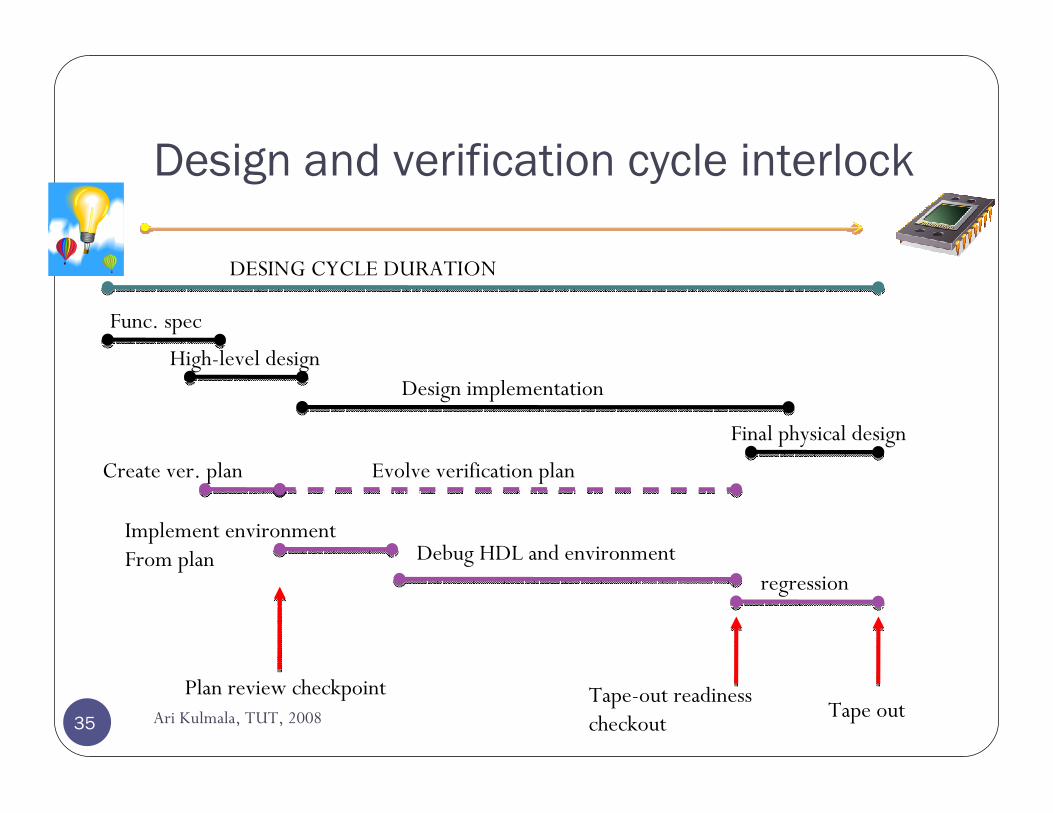
Design and verification cycle interlock
Func. spec
DESING CYCLE DURATION
High-level designDesign implementation
Final physical design
Create ver. plan Evolve verification plan
Implement environmentFrom plan Debug HDL and environment
regression
Plan review checkpoint Tape-out readinesscheckout
Tape out35 Ari Kulmala, TUT, 2008
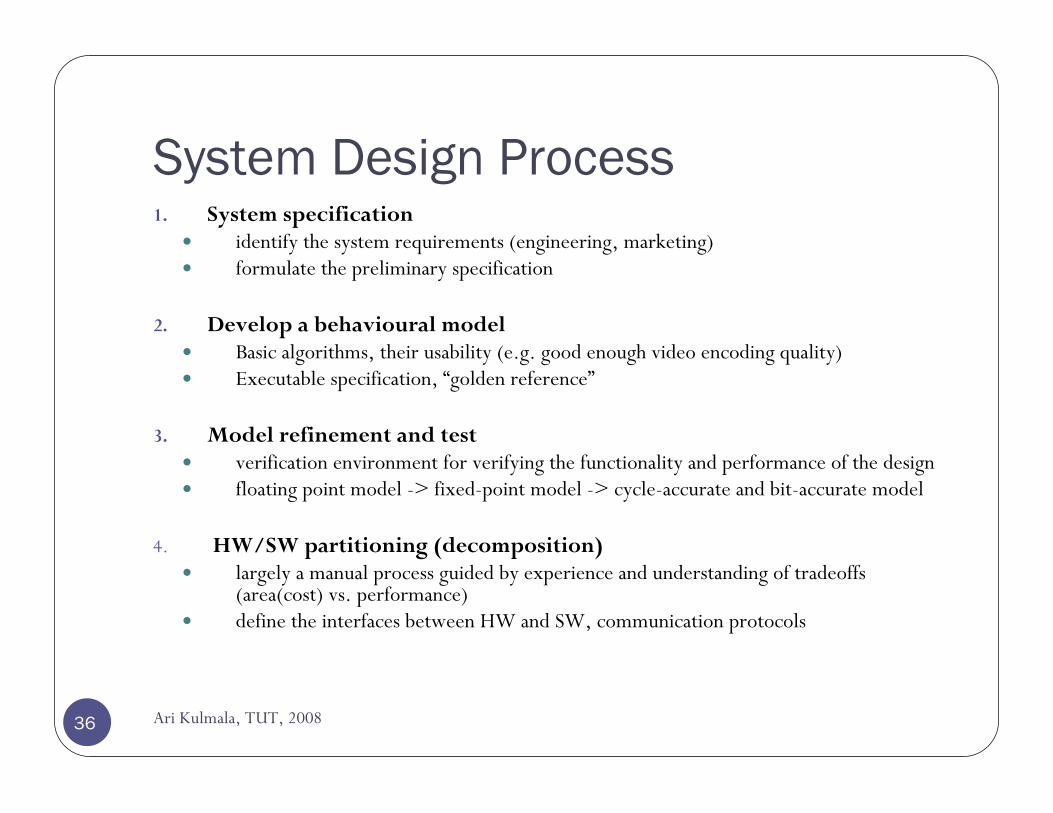
System Design Process
36
1. System specificationidentify the system requirements (engineering, marketing)formulate the preliminary specification
2. Develop a behavioural modelBasic algorithms, their usability (e.g. good enough video encoding quality)Executable specification, “golden reference”
3. Model refinement and testverification environment for verifying the functionality and performance of the designfloating point model -> fixed-point model -> cycle-accurate and bit-accurate model
4. HW/SW partitioning (decomposition)largely a manual process guided by experience and understanding of tradeoffs (area(cost) vs. performance)define the interfaces between HW and SW, communication protocols
Ari Kulmala, TUT, 2008
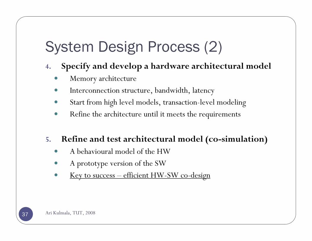
System Design Process (2)
37
4. Specify and develop a hardware architectural modelMemory architectureInterconnection structure, bandwidth, latencyStart from high level models, transaction-level modelingRefine the architecture until it meets the requirements
5. Refine and test architectural model (co-simulation)A behavioural model of the HWA prototype version of the SWKey to success – efficient HW-SW co-design
Ari Kulmala, TUT, 2008
System Design Process (3)
38
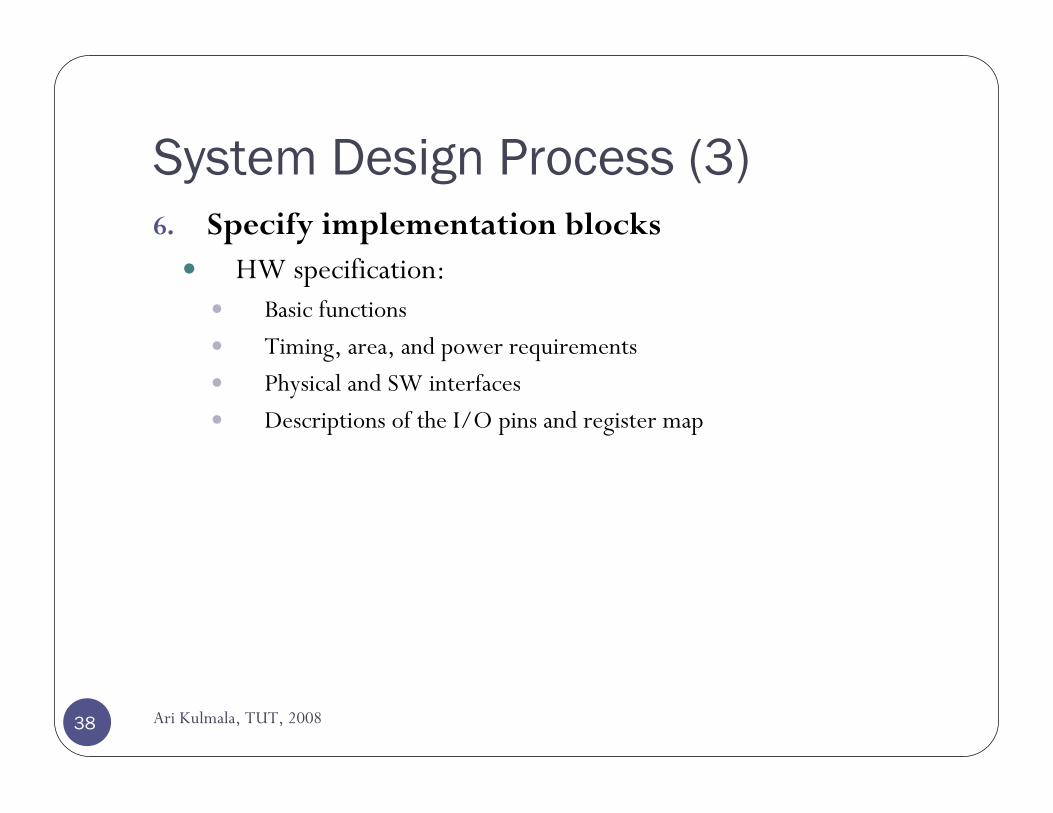
6. Specify implementation blocksHW specification:
Basic functions
Timing, area, and power requirements
Physical and SW interfaces
Descriptions of the I/O pins and register map
Ari Kulmala, TUT, 2008
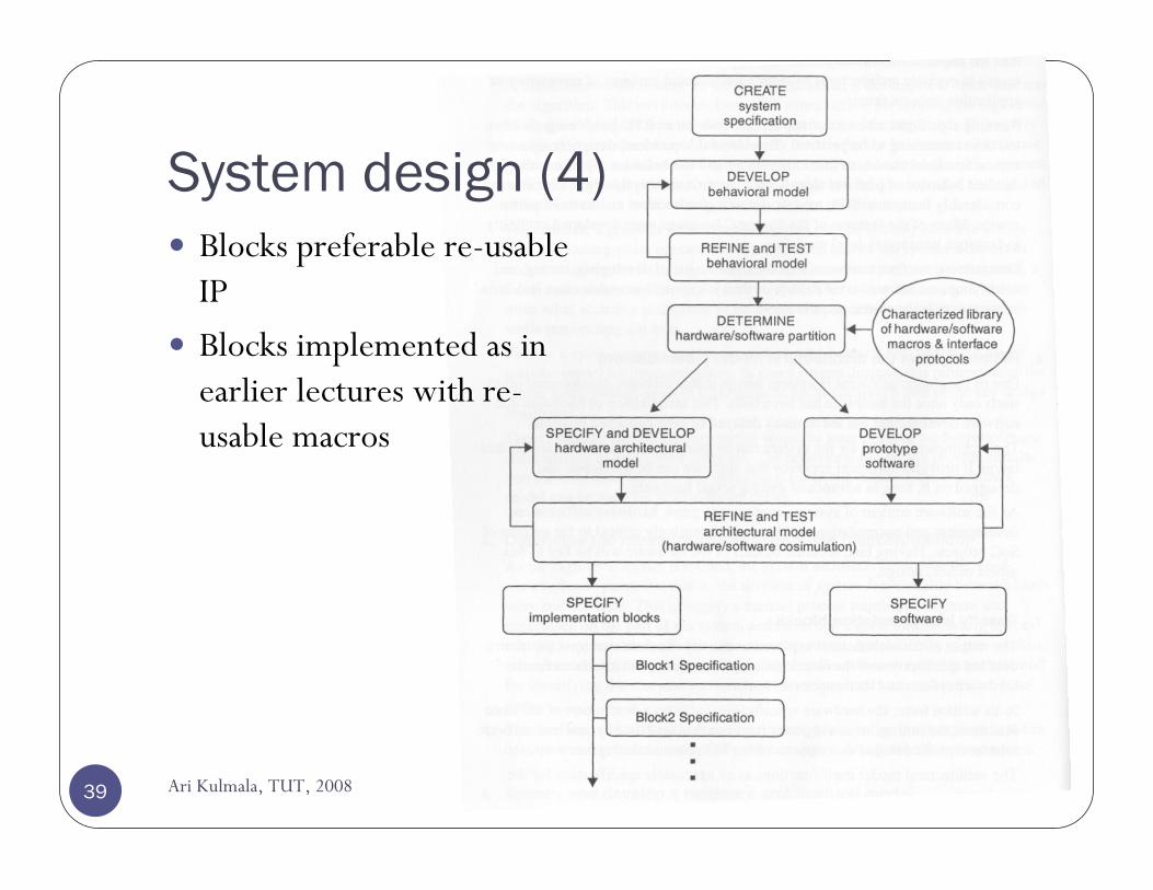
System design (4)
Ari Kulmala, TUT, 200839
Blocks preferable re-usable IP
Blocks implemented as in earlier lectures with re-usable macros
Integrating macros into a SoC
Ari Kulmala, TUT, 200840
Problems in integrating IP
Ari Kulmala, TUT, 200841
Interfaces do not work as documentedfor example, some pin is inverted
Misunderstanding of the block’s function
Functional bugs (…)
Someone needs to get familiar with the IP
Documentation is incomplete
Interface of the IP is proprietary (does not match used bus)
Verification models poor (abstract, fast models)
Limited support from IP provider
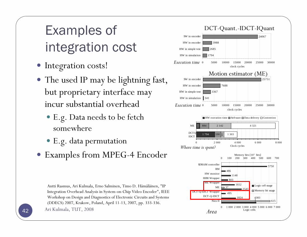
Examples of integration cost
Ari Kulmala, TUT, 200842
Integration costs!
The used IP may be lightning fast, but proprietary interface may incur substantial overhead
E.g. Data needs to be fetch somewhereE.g. data permutation
Examples from MPEG-4 Encoder
2685
3988
24067
1794
0 5000 10000 15000 20000 25000 30000
HW in simulation
HW in simple test
HW in encoder
SW in encoder
clock cycles
3367
7688
25751
341
0 5000 10000 15000 20000 25000 30000
HW in simulation
HW in simple test
HW in encoder
SW in encoder
clock cycles
1 794 590
884 2 142
1 303
4 321341
301
0 2 000 4 000 6 000 8 000
ME
Clock cycles
HW execution t ime Software Data delivery Contention
DCTQIDCT
25431652
803
486
5750
4951824 4383
1148
37
615
0 1 000 2 000 3 000 4 000 5 000 6 000 7 000
Nios II
DCT-Q-IDCTDCT-Q-IDCT Wrapper
ME
ME Wrapper
HIBI WrapperHW monitor
RMSDRAM controller
Logic cells
0 100 200 300 400 500 600 700Memory bits [103 bits]
Logic cell usage
Memory bit usage
Motion estimator (ME)
DCT-Quant.-IDCT-IQuant
Execution time
Execution time
Where time is spent?
Area
Antti Rasmus, Ari Kulmala, Erno Salminen, Timo D. Hämäläinen, "IP Integration Overhead Analysis in System-on-Chip Video Encoder", IEEE Workshop on Design and Diagnostics of Electronic Circuits and Systems (DDECS) 2007, Krakow, Poland, April 11-13, 2007, pp. 333-336.
Selecting the IP, criteria
Ari Kulmala, TUT, 200843
GeneralQuality of the documentationRobustness of design
”Proven in silicon”
For hard macroCompleteness of the design and verification environment
Functional, timing, synthesis, floorplaninng modelsIf CPU, compilers, debuggers
Physical design limitationsAspect ratio, blockage and porosity of the macro (how much it blocks routing)
For soft macroRobustness of verification environment
Rich set of models and monitors for automated stimulus and checkersEase of use
Interfacing the macro to the rest of the designUser-friendly installation and synthesis scripts, tools in general
SystemC
Higher abstraction level language for system modeling
Ari Kulmala, TUT, 200844
Fundamentals of SystemCSystemC is based on C++Primary goal of SystemC to enable system-level modeling
Systems implemented in SW, HW, or some combination of thoseRequirements for system-level design language
Specification and design at various levels of abstractionFast simulation speed to enable design-space explorationIncorporation of embedded software (SW) codeCreation of executable specification of design intentCreation of executable platform modelsConstructs allowing the separation of computation and communication
Needs to support wide range of models of computation and communication, levels of abstraction, and methodologies used in system design
E.g. DSP problems naturally map to a dataflow or Kahn process network (KPN) models
Ari Kulmala, TUT, 200845
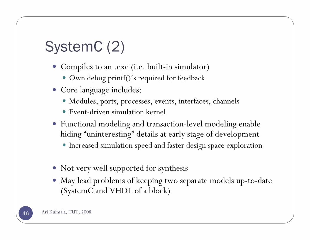
SystemC (2)Compiles to an .exe (i.e. built-in simulator)
Own debug printf()’s required for feedback
Core language includes:Modules, ports, processes, events, interfaces, channelsEvent-driven simulation kernel
Functional modeling and transaction-level modeling enable hiding “uninteresting” details at early stage of development
Increased simulation speed and faster design space exploration
Not very well supported for synthesisMay lead problems of keeping two separate models up-to-date (SystemC and VHDL of a block)
Ari Kulmala, TUT, 200846
Summary
Ari Kulmala, TUT, 200847
Increasingly complex systems need new methodologiesHierarchical, re-usable design style is the current solutionIn future, maybe new design methodologies?Formal verificationExecutable specifications (what goes around comes around)
Divergence to two types of SoCsHigh-performanceLow-power
Several advances and active research required in order to keep on pushing the technology in its limitsParallel processing is the only way to increase performance
New methodologies for SW programmers need to be adaptedCurrently, tool support for parallelization is weak
System design nowadays ”parallel continuous refinement” (Spiral flow)