Embed Size (px)
Citation preview
8/2/2019 tokyo2003
http://slidepdf.com/reader/full/tokyo2003 1/1
Dielectric Fluid Flow in Die -Sinking EDM Gap ○Serkan CETIN, Yoshiyuki UNO, Akira OKADA,
and Yoshifumi KAWAZOE
Okayama University, Department of Mechanical Engineering
1. IntroductionEjection of debris from the working gap in EDM is an important
phenomenon for stable and precise machining. Therefore, the
relationship between the flushing action of the electrode and the
behavior of the debris is of technical interest [1,2]. Recently with the
help of high-speed jump function of linear motor equipped ED
machines, the debris disposal has improved even for deep machining
for no-flush machining [3]. This paper deals with the dielectric fluid
flow in working gap during electrode jump for different jump rates
and heights.
2. Experimental Analysis
A dummy electrode-workpiece is fabricated to simulate the
real dielectric flow in working gap, where the dummy electrode
moves with the same real machining jump parameters. The
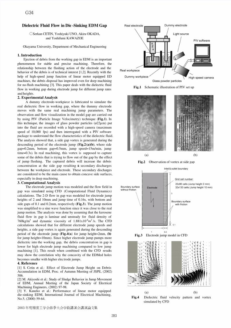
observation and flow visualization in the model gap are carried outby using PIV (Particle Image Velocimetry) technique (Fig.1). In
this technique, the images of glass powder particles (ø22µm) put
into the fluid are recorded with a high-speed camera (maximum
speed of 10,000 fps) and then interrogated with a PIV software
package to understand the flow characteristics of the dielectric fluid.
The analysis showed that, a side gap vortex is generated during the
descending period of the electrode jump ( Fig.2(a)(b), where side
gap=0.2mm, bottom gap=0.5mm, jump speed=15m/min, jump
time=0.3s). In real machining, this vortex is supposed to capture
some of the debris that is trying to flow out of the gap by the effect
of jump flushing. The captured debris will increase the debris
concentration at the side gap resulting in secondary discharges
between the workpiece and electrode. These secondary discharges
are considered to be the main cause to obtain concave side surfaces,
especially in deep machining.
3. Computational AnalysisThe electrode jump motion was modeled and the flow field in
gap was simulated using CFD (Computational Fluid Dynamics)
calculations. The 2-D flow in gap was modeled for electrode jump
heights of 2 and 10mm and jump time of 0.16s, with bottom and
side gaps of 0.1 and 0.2mm, respectively (Fig.3). The jump motion
was simplified to a sine wave function since it was close to the real
jump motion. The analysis was done by assuming that the kerosene
fluid flow in gap is laminar and unsteady for fluid density of
760kg/m3 and dynamic viscosity of 1.881x10⁻⁶m2 /s. The CFD
calculations showed that for different electrode jump speeds and
heights, a side gap vortex is again generated during the descendingperiod of the electrode jump (Fig.4(a) for jump height=2mm, (b)
for jump height=10mm). Since higher electrode jump pumps more
dielectric into the working gap, the debris concentration in gap is
lower for high electrode jump machining compared to low jump
machining [1]. This result when combined with the CFD results
may show the correlation why the concavity of the EDMed holes
becomes smaller with higher electrode jumps.
4. Reference
[1] S. Cetin et al.: Effect of Electrode Jump Height on DebrisAccumulation in EDM, Proc. of Autumn Meeting of JSPE, (2002)
506. [2] M. Akiyoshi et al.: Study of Sludge Behavior in Jump Movementof EDM, Annual Meeting of the Japan Society of Electrical
Machining Engineers, (2002) 97-98.[3] Y. Kaneko et al.: Performance of linear motor equippeddie-sinking EDM, International Journal of Electrical Machining,
No.5, (2000) 59-64.
Fig.1 Schematic illustration of PIV set up
Fig.2 Observation of vortex at side gap
Fig.4 Dielectric fluid velocity pattern and vortex
simulated by CFD
(a) (b)
(a) (b)
Fig.3 Electrode jump model in CFD
2003年度精密工学会春季大会学術講演会講演論文集
− 283−
G34


