Embed Size (px)
Citation preview


TOPICAL REPORT NUMBER 1 . MARCH1990
Tidd:The Nation�s FirstPFBC Combined-CycleDemonstration
Prepared jointly by:
U.S. Department of EnergyAssistant Secretary for Fossil Energy
American Electric Power Service Corporation
Cover photo:Shipped up the Ohio River, the pressurevessel passes AEP�s Cardinal plant as thebarge nears Tidd, the red brick powerplant at the far right, ushering in a new erafor clean coal technologies.
ContentsForeword 2 Plant Systems 11
Preface 3 Tidd Fact Sheet 19
Introduction 4 Project Progress 20
Benefits of PFBC Technology 5 Tidd Test Program 24
Need for the Demonstration 7 Environmental Monitoring 26
Repowering Tidd 9 Commercialization 29
Tidd Power Island 10 References 32

With this first issue of Clean CoalTechnology, a new series of topical
Foreword reports on the demonstration program,we hope to forge an essential link with
Coal�s abundance makes it one of the potential users of the technologies andnation�s most important strategic the many decision makers who playresources in building a more secure important roles in determining theenergy future. However, the characteris- commercial applicability, viability, andtics of coal tend to inhibit its greater use success of innovative and new energyas a fuel. technologies. This series will provide a For coal to reach its full potential, forum for communicating the potentialeconomically competitive and advanced of the technologies and the status andcoal-using technologies and systems accomplishments of the projects.must be developed� and they must be Innovative clean coal technologiesresponsive to diverse energy markets, offer tremendous potential as a part ofvaried consumer needs, and stringent the solution to the many complex andenvironmental requirements. integrated problems we face in our If there is one effort that can best rapidly changing energy arena. Thisdefine our unique opportunity to merge series of topical reports will be one oftechnological know-how with goals for a the many efforts undertaken to commu-cleaner environment and continued nicate vital information from theeconomic prosperity, it is the Clean Coal demonstration program about techno-Technology Demonstration Program. logical opportunities that could signifi- A government-industry partnership, cantly reduce or perhaps eliminate thethis program is demonstrating, at threat of acid rain damage in the future,commercial scale, a new generation of while at the same time create theinnovative coal-utilizing processes in a capability to solve the anticipatedseries of �showcase� plants across the problems in meeting long-range energycountry. For many technologies, these requirements.demonstrations are the culmination of 15to 20 years of research and developmentefforts that have yielded major improve-ments in the environmental and eco-nomic performance of coal-based energy Robert H. Gentile
technologies. For U.S. power and Assistant Secretary
energy industries, the demonstration Fossil Energy
projects represent the final step over the U.S. Department of Energy
threshold between the research labora-tory and the commercial market.
This final step will occur only if theconcepts and equipment developed inthe demonstration projects are replicatedand successfully deployed into themarketplace. Such deployment canoccur only if decision makers are fullyinformed about their options.
2

release of proprietary data and controlledoperational information.
Preface Clean Coal Technology, a series oftopical reports, is one means to achieve
The Clean Coal Technology these goals.Demonstration Program is a unique joint Prepared jointly by the industrialventure of industry and government. It participant and the government�sis a cost-shared effort to develop program and project managers, theseadvanced coal-based technologies that reports will establish a communicationoffer numerous options for addressing a link among industry, federal and statewide range of energy issues, including government, and the public. Each reportacid rain, global warming, improved will contain sufficient information toenergy efficiency, energy security, and track a project�s progress, determine itsenvironmental quality, status, and evaluate its potential. Each In nearly every phase of the report lists sources of indepth informa-program�s implementation, precedent tion on commercial aspects.setting procedures have been imple- This topical report features PFBC, ormented in joining government require- pressurized fluidized-bed combustionments to the commercial requirements of technology, and describes the status ofindustrial participants, who by law pay one of the most advanced demonstrationat least half the costs. Cooperation has projects in the program. The project asbeen essential in preparing procedures well as the report are outstandingthat enable both government and examples of what can be achievedindustry to pursue mutual and separate through the cooperation of industry andgoals. In the relationships established, government. This first issue introducesindustry is the performer, the owner, and a new concept for distributing infor-the implementer. The government mation as it is produced from theshares in the cost, provides recommen- demonstrations.dations, and ensures that the program�s The Clean Coal Technology series isultimate goal� commercialization of a designed to stimulate interest in thesuite of advanced coal-using technolo- program, facilitate technology transfer,gies� is achieved, and encourage commercialization by Some of the demonstration projects those most interested and prepared to doare approaching the stage where useful so. The series is an evolving conceptdesign, construction, or operational data with the flexibility to be refined so thatare being generated. The time is the information can remain relevant andopportune for communicating these satisfy user needs.results to the industrial community andto those who will participate in keydecisions concerning the commercialapplication of clean coal technologies.However, a balance must be achieved Dr. C. Lowell Miller
between the government�s responsibility Associate Deputy Assistant Secretary
to see that the public reaps full value for Office of Clean Coal Technology
its share of the funding and the industrial U.S. Department of Energy
participant�s concerns about inadvertent
3

Tidd:The Nation�s FirstPFB C Combined- CycleDemonstration
idd, an electric generating station blades to survive in a large-scale,Project Participants in Brilliant, Ohio, will have the coal-fired, operating plantOhio Power Company nation�s first pressurized flu- American Electric Power Service Corporation idized-bed combustor (PFBC) to operate • Demonstrate the ability to controlOhio Coal Development Office in a true combined-cycle mode. And for an integrated combined-cycleU.S. Department of Energy the first time in the U.S., this emerging system in utility operation.
clean coal technology will power anPFBC Vendor operating, commercial-scale plant. Government and industry are jointlyASEA Babcock Almost all facets of the project funding the $1 85-million project. The
involve pioneering efforts. Tidd will be American Electric Power Company, Inc.Contacts the first PFBC facility in the U.S. to: (AEP) is providing $114.8 million, andDr. C. Lowell Miller the State of Ohio�s Coal DevelopmentAssociate Deputy Assistant Secretary for • Burn high-sulfur coal in full Office is contributing an additional Clean Coal Technology compliance with existing $10 million, for a total of $124.8 millionFE-22 environmental requirements from industry sources. To this amount,U.S. Department of Energy the U.S. Department of Energy (DOE) isWashington, DC 20585 • Be designed in accordance with adding $60.2 million.(202)586-7150 U.S. codes and standards
The project involves modernizing aMarshall 0. Julien • Have the pressure vessel and 46-year-old power plant with technologyVice President� Communications combustor internals assembled that can burn coal efficiently while re-American Electric Power Service Corporation off-site and shipped via barge to moving sulfur and significantly reducing1 Riverside Plaza the site as a complete module nitrogen pollutants, both thought to con-Columbus, OH 43215 tribute to acid rain. Repowering Tidd(614)223-1660 • Use cyclones to clean up hot gas offers the added advantage of boosting
for an operating gas turbine power output while lowering emissions.
• Demonstrate the ability of in-bed The owner of the Tidd plant is thetube bundles and gas turbine Ohio Power Company (OPCo), an AEP
4
T

subsidiary. Electricity produced at Tidd a PFBC combined-cycle plant offers The project site is AEP�s deactivated Tidd
will be dispatched by AEP into its several major advantages: power plant on the Ohio River near Brilliant,
will be dispatched by AEP into its • Low SO2 and NOx emissions Ohio. The PFBC vessel is housed in the new
transmission system. The American • Lower capital and operating costs building (black walls, white roof) adjacent to
Electric Power Service Corporation • Increased thermal efficiency the plant.
(AEPSC), another AEP subsidiary, is • Fuel flexibilityserving as the utility�s agent and is • Modularitymanaging the project. The PFBC-related equipment is being supplied byASEA Babcock, a partnership between More than 90% of the sulfur releasedThe Babcock & Wilcox Company while burning coal can be removed in(B&W) and ASEA Brown Boveri the PFBC process. NO~ can be reducedCarbon (ABB Carbon). by 50% to 70%.
Capital and operating costs for PFBCare lower than for conventional coal
Benefits of PFBC fired boilers with flue gas scrubbers.Technology Typical savings are roughly 10% of
costs. Factors contributing to these A clean coal technology (CCT) savings include higher heat transfer ratescapable of burning high-sulfur coal to in the boiler, smaller unit size, highergenerate electricity efficiently and eco- plant efficiency, elimination of costlynomically, PFBC can do so while meet- add-on pollution control equipment, anding stringent New Source Performance easier solid waste disposal.Standards (NSPS). Compared to a In PFBC, the rate at which heat isconventional pulverized coal-fired plant, transferred from the bed to the tubes is
5

four to five times greater than in a quality (e.g., its heat, ash, and sulfurconventional coal-fired boiler. PFBC content, or its fusion temperature).combined-cycle technology offers the Modularity makes PFBC combinedpotential to achieve thermal efficiencies cycle technology an attractive option foras high as 45%, a significant improve- either repowering or new applications.ment over the 36% efficiency of today�s PFBC modules, available in two sizes,coal-fired plants. can be installed individually or in The fuel flexibility offered by a multiples. The modules are suitable forPFBC boiler enables a plant to burn a installation in existing facilities, where awide range of coal, regardless of its PFBC module would replace a unit�s
6
Pressurized Fluidized-Bed Combustion
In a fluidized-bed combustor, 1,600 0F, or almost half that of a
crushed coal with limestone or conventional boiler. This is also
dolomite (called �sorbents�) is the temperature range within
suspended by jets of air. This which the reaction of SO2 with�bed� of coal and sorbent actually limestone and dolomite is most
floats inside the boiler, tumbling effective. Furthermore, this
in a way that resembles a boiling range is lower than the
fluid, hence the name �fluidized.� temperature at which substantial
Inside a PFBC boiler, pressures amounts of NO~ are formed.
are up to 16 times higher than To maintain bed temperature
normal atmospheric pressure. within the desired range, heat is
As the coal burns, sulfur is extracted continuously by
released. The limestone acts like immersing cooling tubes in the
a chemical �sponge� to capture fluidized bed. Water (or another
the sulfur before it can escape working fluid) flows through the
the boiler. The sulfur-laden bundle of tubes, changes to
sorbent forms a dry waste. steam as it is heated, and is
Some of the waste is removed routed through a steam turbine to
with the bed ash through the generate electricity.
bottom of the boiler. Smaller ash Hot, pressurized flue gases
particles, or �fly ash,� are carried from the combustor flow through
out of the boiler and captured by �cyclone d ust collectors� to
cyclone dust collectors. remove particulate matter that
Also, because the tumbling could foul, corrode, or erode the
motion of the coal enhances the blades of the gas turbine. After
burning process, combustion cleaning, the hot gases are
temperatures can be kept routed to a gas turbine and
relatively low� to less than expanded to generate electricity.

boiler, or in new plants, where one or the performance of PFBC systems atmore modules would be installed, larger sizes have been based on these In repowering, the old boiler is earlier tests and engineering estimates.replaced while most of the remaining Without actual operating experience,facilities are retained, although some however, uncertainty and risk aremay be refurbished. Because the facility inherent, and this risk can be a barrier tohas already been sited, built, and commercial acceptance.connected to the power grid, repowering The purpose of the Tidd PFBCcan be an economical alternative to demonstration is to verify expectationsconstructing a new power plant. about the technology�s economic, envi- Repowering with combined-cycle ronmental, and technical performancePFBC technology enables an existing and to collect actual data from a utility-plant, such as Tidd, to meet environ- operated facility while it is subjected tomental constraints while at the same �real world� conditions.time producing more power than the Potential users must be confident thatoriginal plant. Depending on the appli- the systems are not only technically In fluidized-bed combustion, crushed coal
cation, the capacity of the existing plant feasible but also viable in the real world mixed with sorbent burns while suspended
can be increased by up to 25% with with all its attendant complexities. by jets of air. Water flowing through tubes
PFBC combined-cycle technology. In 1989, DOE�s Innovative Control submerged in the hot, turbulent bed changes
When a new power plant is built, Technology Advisory Panel assessed to steam which drives a steam turbine. The
PFBC modules can be installed incre- impediments to the commercialization of hot flue gases are cleaned in cyclone dust
mentally in phases, making it easier for a clean coal technologies. The Panel collectors and then routed to a gas turbine.
utility to manage capital investmentwithout sacrificing economies of scale.Staged, modular expansion shortens con-struction time and lowers the costsrequired to bring new capacity on line,In addition, the reliability of a string ofparallel modules is typically higher thanfor a single, large unit.In sum, the many features of PFBCcombined-cycle systems are expected tomake this technology an attractive andhighly competitive option in the suite ofemerging clean coal technologies.
Need for theDemonstration
Never before has PFBC technologybeen employed in the U.S. in a commer-cial facility. Previous tests have beenconducted at far smaller scales and incontrolled settings. Expectations about
7

described a number of barriers relating There are costs associated withto economic risks, regulatory concerns, bringing a technology to full commercialand environmental problems. maturity. A new technology can have a
higher cost at first than the technology itEconomic Risks is meant to replace. Typically, a first-of-
a-kind facility will have comparatively Economic problems and risks result higher development, testing, engineeringfrom various market imperfections or and design, and fabrication costs thanfailures such as unrecognized value of will subsequent plants. Consequently,research and development, imperfect the true cost savings offered by the newregulation, imperfect knowledge, technology usually cannot be realizedenvironmental externalities, and unrec- until the third to fifth plant has enteredognized public needs, the marketplace.
8
Barriers to New Technologies
In its 1989 Report to the institutional problems inherent in
Secretary of Energy Concerning rate regulation today cause
Commercialization Incentives, utilities to be reluctant to spend
DOE�s Innovative Control large amounts of money for new
Technology Advisory Panel generation projects of any kind,
summarized barriers to clean including CCTs. Also siting and
coal technologies as follows: permitting regulations can be
�These new technologies duplicative and overly complex.
face potential impediments of �Some environmental air quality
three types. regulations may also potentially �First, because these constrain new CCT demonstra-
technologies are new, and in tion and deployment, despite the
many cases have yet to be fact that both the regulations and
demonstrated at the commercial the CCT technologies have the
scale, engineering estimates of goal of a cleaner environment.
actual cost and performance are Some regulations or policies may
still uncertain. Thus, it is too create uncertainties because of
early to expect utilities or other lack of clarity, while others provide
firms to build these technologies CCT demonstration with
on a commercial scale without inadequate time for compliance.
some reduction of economic risk. In addition, in some cases,
�Secondly, despite the best environment permitting and/or
efforts of regulators to properly approval may be subject to delays
balance the interests of electric which increase project uncertainty
ratepayers and shareholders, and/or costs.�

Developers of �pre-commercial� CCT Developers may be reluctant to proceedplants risk higher than expected project if uncertain about how current regula-capital costs and operating costs and tions will be enforced or unsure as tolower than expected performance. whether or not the project would comply
with future regulations.Regulatory Concerns Inflexibility of regulations can also
present barriers. For example, if a utility Protecting ratepayer interests while at voluntarily improves controls andthe same time providing a reasonable reduces emissions at a power plant,business environment for utilities is a requirements for even tighter controlscomplex and difficult task, one in which could be triggered. Because emissionbalance is very hard to achieve, waivers might not be allowed or might The Innovative Control Technology be restricted, units that just miss comply-Advisory Panel observed that problems ing with newer, tighter standards couldfaced by utilities and other regulated de- be faced with substantial added expensevelopers of CCT projects tend to involve in order to comply.electricity rate regulation and/or the statesiting and project approval process. Rate regulation can significantlyimpede CCT investment if developers Repowering Tiddare concerned or uncertain about thepotential for cost disallowances, inade- Originally commissioned in 1945, thequate rates of return, financial effects of Tidd plant was prematurely retired in thedelayed construction projects, and regu- late 1 970s because it was unable to meetlatory lag. In addition, complex and emission standards. At that time, OPColengthy siting and project approval determined that it would not have beenprocesses may be concerns. economical to retrofit the plant with the
necessary controls to meet the standards.Environmental Problems However, Tidd is now being repowered
with an emerging clean coal technology.Ironically, CCT demonstrations are The old pulverized coal-fired boiler is
subject to a number of environmental being replaced with a PFBC boiler, andimpediments. The problem is not due to a gas turbine is being added. The PFBCthe intent of the environmental regula- combined-cycle system is being used totions but occurs during implementation repower Unit 1, one of two 11 0-MWeor enforcement. units at the Tidd site. Environmental permitting processes Much of the original equipment iscan be long and costly, and delays tend being refurbished. The plant�s steamto increase borrowing costs of a project. cycle is utilizing many of the existingTime limits in some environmental and components, including the steam turbineconstruction permits increase a devel- generator as well as condensate andoper�s uncertainty and costs if repeated feedwater heaters and pumps.applications are required. Many of the service buildings, control Uncertainty in the definition or systems, and piping systems also areenforcement of regulations or in the being incorporated. The existingfuture status of the regulations can have structures for storing and handling coala major impact on CCT projects. and dolomite are also being used, as well
9

Many existing facilities at Tidd are being as a 138,000-volt switchyard from which new building next to the wall of Tiddrefurbished and reused, such as the steam power will be sent into AEP�s transmis- Unit 1 in one of the original ash ponds.cycle, fuel storage and handling facilities, sion system. The new economizer, electrostaticand switchyard. A new building adjacent to Major new equipment being installed precipitator, ash silos, and electrical vessel,Tidd Unit 1 houses the PFBC pressure includes the PFB combustor and related control building are located nearby.vessel, gas turbine, and other new systems. components (including the boiler, bed This layout allowed maximum use of
ash reinjection system and cyclones), the existing Tidd facilities.gas turbine, coal and sorbent preparationand injection systems, the economizer,the electrostatic precipitator, ash remov-al and disposal systems, and electricalcomponents (including transformers and Tidd Power Islandswitchgears). It also has been necessaryto construct new foundations, buildings, The Tidd PFBC Demonstrationand piping and electrical systems needed Project will be the nation�s first PFBCto integrate the PFBC system with the plant to operate in a true combined-cyclebalance of the plant. mode, with both a gas turbine and aThe new PFBC power island, which steam turbine generating electricity.includes the combustor, gas turbine, and Tidd�s new PFBC power island,coal and sorbent systems, is located in a which is being incorporated into the
10

existing conventional steam cycle, will adjustment by dilution) controls the finalhave a steam flow of 440,000 pounds per temperature of steam exiting the boiler.hour at 1,300 psia and 925 0F and a gross After passing through the in-bedelectrical output of 74 MWe (58 MWe secondary superheater, the steam exitsfrom the steam turbine and 16 MWe the boiler at 1,335 psia and 925 0F.from the gas turbine). During start-up and in the event of a The Tidd plant will demonstrate a steam turbine trip, a 50% bypass systempressurized bubbling fluidized-bed oper- to the condenser and a pressure controlating at about 175 psia. Pressurized valve to the atmosphere serve to disposecombustion air is supplied by the gas of excess steam while controlling theturbine. In the combustor, air fluidizes boiler pressure-temperature decay. Inand entrains bed materials consisting of the event of a loss of plant power or thethe fuel (a coal-water paste), coal ash, boiler feed pumps during operation, aand dolomite sorbent. backup feedwater injection system main- After leaving the boiler, the hot gases tains water flow to the boiler circuitsand entrained ash particles pass into a contained in the slumped bed and thustwo-cyclone train. The cyclones remove exposed to heat.98% of the entrained ash. The clean, hotgases leave the pressure vessel via acoaxial pipe and are expanded through ahigh-pressure turbine and a low-pressure Plant Systemsturbine, then sent to the turbine exhaust Tidd�s new PFBC power island includes the
gas economizer. The gas is further One of the key objectives of the Tidd combustor vessel, gas turbine, and fuel
cleaned in an electrostatic precipitator demonstration project is successfully preparation system. Other related
and then emitted to the atmosphere. scaling up the PFBC system from pilot equipment, such as the economizer,
The steam cycle is a Rankine cycle plant size to the 200-MWt Tidd plant. electrostatic precipitator, ash silos, and
with a once-through boiler. Condensate The 15-MWt integrated pilot plant, electrical controls, also were added.
(from a condenser) is heated in threestages of low-pressure heaters and thegas turbine intercooler as it is pumped tothe deaerator. The feedwater pressure isthen increased to 820 psia and furtherheated. The flow is then further pressur-ized to 2,000 psia by the feedwaterpump and directed to the economizer,where it is preheated to 480oF by thegas turbine exhaust before being routed tothe boiler.
The feedwater passes through the boilerbottom zone and into the in-bed evaporatorsurface. Here, steam is formed andconveyed to the vertical separator. Thesteam is two-phase up to about 40% loadand slightly superheated at full load. Afterthe steam enters thein-bed primary superheater, sprayattemperation (which is temperature
11

designed for a relatively low differential
pressure even though the process pressure
is relatively high.
The pressure vessel is externally
insulated and is designed for internal
operating conditions of 590 0F and
170 psia. It consists of a vertical cylin-
drical shell about 70 feet high and 44 feet
in diameter with elliptical heads.
The pressure vessel heads include
removable service openings that allow for
the removal of internal components. In
addition, internal and external service
platforms, lifting devices, and access
doors are provided to permit service and
maintenance of both the internal and
external systems.
PFBC Boiler
The PFBC boiler enclosure is designedwith membrane water wall construction.At normal operating loads, the boiler is asub-critical, once-through unit. There arethree major sections in the boiler� theboiler bottom, the bed zone, and thefreeboard.
The boiler bottom consists of fluidizingair ducts arranged on top of a pair ofmembraned water wall hoppers. The
hoppers, which remain full of ashThis scale model of Tidd�s pressure vessel located at the PFBC Component Test during operation, direct the spent bedshows (1) the dolomite feed system, Facility (CTF) in Sweden, was designed ash to the bed ash removal system.(2) boiler tubes suspended in the fluidized to test components, process variables, The boiler�s bed zone is designed as abed, (3) coal feed lines, (4) vessel wall, and control systems at near-commercial deep (10.5 feet), tapered, fluidized bed(5) two-stage cyclone train, and (6) bed ash size. The testing performed at the CTF in which the superheater and evaporatorreinjection vessel. has enabled AEP to verify the design sections are submerged. At full load, all
conditions projected for the Tidd PFBC of the evaporator and superheaterdemonstration plant. surfaces are submerged within the bed.
At reduced loads, the bed level is lower,Pressure Vessel thereby exposing portions of the surface.
The surface above the bed convectively A single cylindrical pressure vessel cools the gases feeding to the gas side,contains the boiler, cyclones, cyclone because the convective heat transferash coolers, and bed ash reinjection rates are lower than those within the bed.system. This arrangement allows the In the freeboard section, excess air incomponents within the vessel to be the hot gas is controlled to 25%. The
12

freeboard is sized to minimize the In scaling up bed area, experience haselutriation (separation) of fly ash by the shown that boiler tube geometry andgas flow and is internally insulated to cut proper air distribution are the mostheat loss on the way to the gas turbine, significant parameters relating to bed Critical design variables for the boiler temperature distribution. Increased bedwere bed temperature and area, operat- area is not expected to be a problem,ing pressure, and residence time, especially since the larger bed area Bed temperature strongly influences minimizes the effects of wall cooling.the process and is related to gas-side Earlier research has also indicatedcorrosion. Experience at the CTF that between 150 and 300 psia, operatingindicated that gas-side corrosion should pressure does not significantly influencenot be a problem if bed temperature is process results. At 170 psia, Tidd�s bedkept between 1,500 and 1,600 0F. will operate well within this range.Above this temperature range, there is Residence time, another criticalgreater risk that high levels of alkali scale-up variable, strongly influencesconstituents will form in the gas stream, sulfur removal and combustionThe Tidd plant is designed to operate at efficiency. Residence time is a functiona bed temperature of 1,580 0F, which is of fluidizing velocity and bed depth.within the acceptable range. Because these two parameters are
13
Component Testing for Commercial Scale-Up
Technical risks associated with 235 psia. The GTE incorporates
scaling up technology to commer- key PFBC-related systems and
cial sizes are reduced by testing components needed for a corn-
the proposed designs and mercial power station.
systems in an integrated facility. Key technological and
Testing of PFBC-related equip- developmental breakthroughs
ment and systems for Tidd was made at the GTE include:
conducted at the Component · Successful continuousTest Facility (GTE) in Sweden. removal of cyclone ash in a
This facility is owned and dry state
operated by ASEA Brown Boveri · Successful utilization of hot
Carbon (ABB Carbon; formerly bed ash reinjection
known as Stal-Laval and then · Successful test of a rotating
ASEA Stal). ABB Carbon is one gas turbine cascade
of the partners in ASEA Babcock, · Successful gas cleaning
the PFBC supplier for Tidd. through a two-stage
Operational since 1982, the cyclone train
GTE is an integrated PFBC pilot · Successful feeding of coal
plant. Its 1 5-MWt combustor can as a paste with less than
be operated at pressures of up to 25% total water content.

similar for both the CTF and Tidd, Air from the combustor pressurescale-up problems are not expected. vessel transports the bed material to and Another area of technical concern in from the reinjection vessels. Thethe development of PFBC technology transport air flow is separated from thehas been in-bed tube erosion. The ash and vented outside the combustordesign of the tube bundle for the Tidd into the main combustion flue gas. Theplant takes advantage of experience from reinjection vessels are normally at thethe CTF, and it is anticipated that tube same pressure as the boiler; however,erosion rates will prove to be acceptable during load decreases, they are at afor commercial applications, slightly lower pressure.
Bed Ash Reinjection System Ash Removal System
Bed level is the main controlling Fine ash collected in the cyclones isparameter in the PFBC boiler. The bed continuously removed by a pneumaticash reinjection system permits rapid transport system. The ash is cooled andchange in the unit load by transferring a portion of the heat is recovered in thebed material to and from a pair of combustion air. Depressurizationreinjection vessels located inside the requires no lockhoppers or valves.combustor pressure vessel. Special Granular bed ash is continuously
Cyclones clean particulates from hot flue handling devices are used to admit bed removed by gravity from the boilergases to prevent fouling and erosion of the material stored in the reinjection vessels bottom hoppers in order to maintain thegas turbine. The Tidd pressure vessel into the bed, thus increasing load. To desired fluidized-bed level. Twocontains seven parallel strings of cyclones, decrease unit load, bed material is parallel lockhoppers, each serving one ofeach with two stages. Pictured are both
stages of cyclones, prior to installation pneumatically transported from the bed the bottom hoppers, are filled andinside the pressure vessel, to reinjection vessels, emptied independently. When full, the
lockhoppers are depressurized byventing and are emptied by gravity into acommon atmospheric-pressure hopper.From here the ash is fed onto an enclosedconveyor system and transported to thestorage silo.
Cyclones
To reduce particulates flowing to thegas turbine, the exhaust gas leaving theupper part of the boiler freeboard passesthrough a series of cyclones. At Tidd, thereare seven parallel strings of cyclones, eachwith two stages of separation. The gas isconveyed from the boiler to the first-stagecyclones through connecting flues. Gasflows from the second-stage cyclones to amanifold and then exits the pressure vessel.It then makes its way through
14

the inner portion of a coaxial pipe and past
the hot gas intercept valves on its way to
the gas turbine. The cyclones and gas
collecting pipe are insulated to minimize
gas temperature loss.
Gas Turbine Generator
The new gas turbine being used for the
demonstration project, the GT-35P, is a
modified ASEA Stal GT-35 that is
uniquely suitable for PFBC applications.
This turbine is arranged in-line on two
shafts. The variable speed, low-pressure
compressor is mechanically coupled to its
driving low-pressure turbine on one shaft.
The high-pressure turbine drives both the
constant speed high-pressure compressor
and the electric generator. An epicyclic
gear reducer couples the electric generator
to the high-pressure shaft.
With this design, combustion gas
temperatures fall when unit load is cut
because the lower bed height exposes
more steam generator tubes. As gas
temperature drops, the low-pressure
shaft slows, lessening the pressure and
flow of combustion air. Thus the free-
spinning low-pressure shaft allows the
air flow to vary with unit load.
The gas turbine in a PFBC combined
cycle system is subjected to very harsh
conditions� and the Tidd demonstration
is no exception. Thus measures have
been taken to ensure the integrity and
operating life of the turbine. At Tidd,
the gas is precleaned using cyclones, and Assembly of the high-pressure turbine stage
Turbine erosion and corrosion as well is shown in the photo (top). Tidd�s gas
Turbine erosion and corrosion as well turbine is arranged in-line on two shafts: the
as deposition phenomena have been variable speed, low-pressure (LP) turbine on
researched extensively. An important one and the constant speed, high-pressure
aspect of the program at the CTF was (HP) turbine on the other.
investigation of the gas-cleanup and
gas-turbine interface. In testing at
turbine inlet temperatures to 1,526 0F, no
blade erosion was found. Selection of
15

16
Hot Gas Cleanup R&D Planned
The Tidd demonstration offers Even though there has beena unique opportunity for devel- extensive development in
oping further advances in PFBC advanced HGCU filtration, AEP
components and systems. An concluded that advanced HGCU
agreement between AEP and technology was not yet ready to
DOE to test advanced hot gas be implemented into the design
cleanup (HGCU) filtration devices of Tidd, but that provisions should
is an example of the synergism be included at Tidd to test such a
possible between demonstration device in the future.
and R&D activities. The 5-year, $20-million HGCU
Historically, gas turbines have research project will test filtration
been fueled from natural gas or devices in a �slipstream.� About
oil; however, Tidd�s gas turbine one-seventh of the combustor
will generate electricity from coal. exhaust gas� 100,000 pounds
The key element at Tidd that per hour at full load� will be
allows the gas turbine to be coal- diverted through this slipstream.
fired are cyclones-devices that Various types of filters will be
impart a swirl to gases laden with evaluated and one or two tested.
fly ash and remove over 98% of Four types of filters are under
the ash particles before the high- study: ceramic crossflow, moving
temperature, high-pressure gas screenless granular bed, ceramic
enters the turbine, candle, and ceramic tube filters.
Although this gas is expected All use ceramic material
to be clean enough to prevent configured in various shapes and
damage to the gas turbine from sizes. Ceramic is used as theparticle erosion, the gas must be particulate barrier because it can
further cleaned to meet withstand harsh conditions.
particulate emissions standards. The filters trap virtually all
A conventional electrostatic particulate matter by acting as an
precipitator accomplishes this. impermeable barrier, in
Ideally, an HGCU device could microscopic pores in the ceramic,
be located between the combus- or in a moving bed of granules as
tor and the gas turbine to remove the gas flows from the fluidized
sufficient particulate matter to bed to the gas turbine.
eliminate the need for the electro- Testing is scheduled to begin
static precipitator; however, this in early 1992 and will be
approach would require a very conducted during the second and
efficient filter capable of operating third years of Tidd�s operational
under comparatively severe phase. During this period, up to
conditions of over 1,500 0F and 7,000 hours of test runs are
180 to 250 psia. planned for the HGCU devices.

the two-cyclone train for gas cleanup at Coal Feed SystemTidd was based on work at the CTF andthe cyclone manufacturer�s experience. A paste feed system is being used. It
Design modifications made in the gas was chosen because of its operatingturbine to improve reliability in PFBC ease, lower capital cost, better flowapplications include decreasing loading control, and better expected availabilityon the first turbine stage by adding an than alternative methods. Also crushedextra stage and increasing stability by rather than pulverized coal is being usedconnecting the high-pressure shaft to the because small particles will elutriatepower turbine shaft by using a gear train. (separate) from the bed. This would be
undesirable as it would reduce theEconomizer residence time needed for efficient
combustion and sulfur absorption and A new, once-through, turbine exhaust would also cause excessive loading ofgas economizer will be used at Tidd. An dust within the cyclones.economizer recovers heat from the gas To form the paste, uncrushed 1-inchturbine exhaust for preheating the coal stored in a 45-ton capacity surgefeedwater. Tidd� s economizer is a hopper is fed into a double-roll crusher. A coal-water paste fuels Tidds PFBC boiler.
modular design with the flue gas flowing A system of conveyors then transports Feed hoppers supply six parallel, hydrauli-
horizontally across vertical, in-line, the crushed coal (1/4-inch) onto a three- cally operated coal-injection pumps. Feed
spirally finned water tubes. It is in series deck screen to eliminate oversized lines leading from each pump carry the
with the condensate heaters and replaces pieces and into a pugmill-type mixer, paste upward and into the boiler.
existing high-pressure feedwater heaters.
Electrostatic Precipitator
After leaving the economizer, the gasenters the electrostatic precipitator. Here,the gas is further cleaned of particulates tothe NSPS level of 0.03 pounds per millionBtu. The gas is then released to theatmosphere via the flue gas stack.
Steam Turbine Generator
The original Tidd plant steam turbinegenerator is being refurbished and willoperate at half of its original rating togenerate 75% of the plant�s 70-MWecapacity. Both the turbine rotor andgenerator field for the steam cycle were onreserve as system spares at another AEPpower plant. Refurbishing the turbineinvolves replacing the first-stage wheeland updating the former water seal systemwith a more effective, new steam sealsystem.
17

The fuel is pumped as a coal-water paste sorbent (1/8-inch) is controlled by awhich is 25% water. A specific distribu- vibrating screen and heated air flowingtion of coal size is used to eliminate through the mill. The sized material isinter-particle motion and to make swept from the mill by the hot air andpumping the paste easier. The coal�s then sorted by a cyclone separator and amoisture is measured on the weigh baghouse. A vibrating screen located atfeeder and water is added to the mixer to the outlet to the cyclone separatorprepare the paste. It then goes directly diverts oversized material back to theinto a fuel feed hopper which has a mill. The final product is transported by1-hour storage capacity. conveyor into a 200-ton sorbent storage The feed hopper supplies six parallel, hopper. The hopper has two outlets tohydraulically operated coal injection feed the sorbent injection system.pumps that deliver the fuel to the boiler. Lockhoppers receive the preparedEach pump feeds fuel into the boiler sorbent at atmospheric pressure. Whenthrough a dedicated fuel nozzle, full, the lockhoppers are isolated from
the storage vessel and pressurized morethan the combustor. Variable-speed
Sorbent Feed System rotary feeders meter the flow of sorbentThe PFBC combined-cycle system is to pneumatic conveying pipes. Whenintegrated using eight process control units Sorbent (dolomite), stored in a 70-ton the lockhoppers are empty, they arelocated in a central control room, shown capacity surge hopper, is first fed into an isolated from the combustor and areunder construction. impact dryer mill. The size of the vented to the atmosphere through a bag
filter. When completely depressurized,they are then ready to be refilled.
Control System
A distributed programmable logicsystem is being used to collect signals andmeasurements. The control system, aBailey NET-90, uses eight process controlunits divided into the following nodes: gasturbine, combustor, steam turbine, balanceof plant, and safety.These units perform the control ofindividual plant items and also most of thecoordinating control, interlocking, andautomatic functions involving groups ofrelated items.
The control system will operate as anintegral-plus-proportional system. Itintegrates the combined-cycle systemthrough a megawatt-demand signal. Thesystem determines the necessary fuel flow,water flow, air flow, and bed level basedon predicted values and biased by feedbackloops.
18

19
Tidd PFBC Combined-Cycle Demonstration ProjectDescription: Electrical output: Combustor vessel:
A PFBC combined-cycle system Net 70 MWe Operating temperature 590 0Fis being used to repower a moth- Gross 74 MWe Operating pressure 170 psiaballed pulverized coal-fired power Steam turbine 58 MWe Diameter 44 ft
plant. Off gases from the combustor Gas turbine 16 MWe Height 70 ftare expanded through a GT-35P gas Weight (total) 1,400 tonsturbine with a steam turbine Fuel and sorbent:
bottoming cycle. A new PFBC Pittsburgh #8 (3.4% sulfur) Combustion:power island is being installed. Dolomite (Ca/S of 1.6) Temperature 1,580 0FExisting steam turbine and site Pressure 170 psia
utilities are being refurbished. Environmental performance:S02 abatement 90% Steam flow:
Participants: NOx abatement 70% Temperature 925 0F
Ohio Power Company Particulates 0.03 lb/106 Btu Pressure 1,300 psiaAmerican Electric Power Solid waste 32.8 lb/106 Btu Flow rate (lb/hr) 440,000 Service Corporation
Ohio Coal Development OfficeU.S. Department of Energy Schedule for Project Phases 1987 1988 1989 1990 1991 1992 1993Funding: I. Design & permitting
DOE $ 60,200,000 II. Procurement, construction & start-upIndustry $124,800,000 Ill. Operation, data collection, reportingTotal $185,000,000 & disposition
Project ProgressThe Tidd cooperative agreement
between AEP, DOE, and the Ohio CoalDevelopment Office was executed in1987. Formal ground breaking ceremo-nies were held in April 1988. Theproject is on schedule, and plant start-up isset for October 1990.
Proceeding on Schedule
Phase I (Design and Permitting) startedin February 1987. Phase II (Pro-curement,Construction, and Start-up) began inDecember 1987.
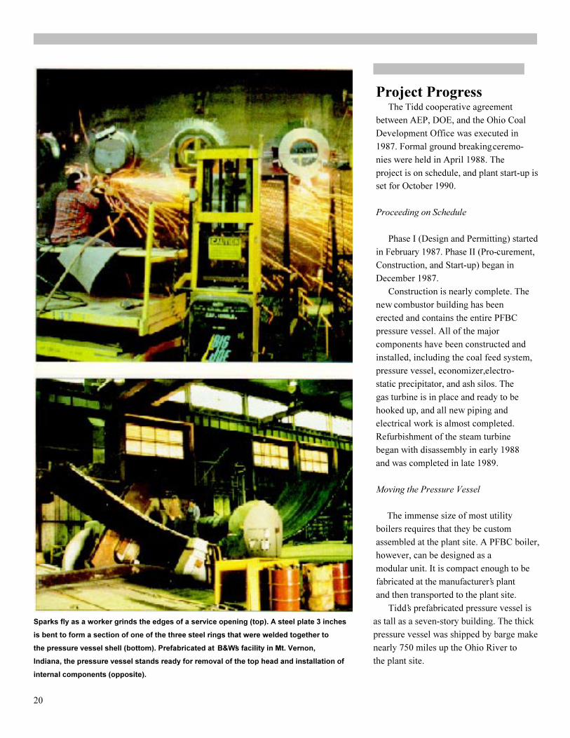
Construction is nearly complete. Thenew combustor building has beenerected and contains the entire PFBCpressure vessel. All of the majorcomponents have been constructed andinstalled, including the coal feed system,pressure vessel, economizer, electro-static precipitator, and ash silos. Thegas turbine is in place and ready to behooked up, and all new piping andelectrical work is almost completed.Refurbishment of the steam turbinebegan with disassembly in early 1988and was completed in late 1989.
Moving the Pressure Vessel
The immense size of most utilityboilers requires that they be customassembled at the plant site. A PFBC boiler,however, can be designed as amodular unit. It is compact enough to befabricated at the manufacturer�s plantand then transported to the plant site.
Tidd�s prefabricated pressure vessel isSparks fly as a worker grinds the edges of a service opening (top). A steel plate 3 inches as tall as a seven-story building. The thickis bent to form a section of one of the three steel rings that were welded together to pressure vessel was shipped by barge makethe pressure vessel shell (bottom). Prefabricated at B&W�s facility in Mt. Vernon, nearly 750 miles up the Ohio River toIndiana, the pressure vessel stands ready for removal of the top head and installation of the plant site.internal components (opposite).
20


The combustor vessel was built over a 2-year span at B&W�s fabrication facilities inMt. Vernon, Indiana. The 44-foot diameter,70-foot tall combustor vessel is the largest�shop-built� vessel in B&W�s history. Bybuilding the vessel and shipping it intact,considerable cost and time savings wererealized.
The vessel holds the fluidized-bedenclosure with boiler tubes and otherassociated equipment. These items werealso constructed as modules for easyassembly into the vessel after being shippedto the Tidd plant. The fluidizedbed boilermodules were built at B&W�s facility atWest Point, Mississippi, and shipped viathe Mississippi and Ohio Rivers to Mt.Vernon for placement inside the cylindricalpressure vessel.
In May 1989, the completed pressurevessel was loaded onto a 276-foot barge forthe river trip to the Tidd site. With the 17-foot high hemispherical head removed, thevessel stood 53 feet. Thevessel assembly and head weighed a totalof 1,392 tons. The entire cargo, consistingof the vessel with internal items, head,transport trailer, and other movingapparatus, totaled 2,200 tons.
The barge passed through 13 locks andunder 49 bridges on its voyage throughIndiana, Kentucky, Ohio, andWest Virginia to Brilliant, Ohio.
High water from late spring rainsnecessitated the addition of water ballast inthe barge to clear a railroad bridge atHenderson, Kentucky. Even more ballastwas added shortly thereafter to improvestability and provide adequate clearanceunder another bridge.
Project engineers had calculated that asuspension bridge at Wheeling, WestVirginia, would pose the tightest squeeze ofthe trip. In the end, the combustor
The vessel, head, internal items, and transport equipment, weighing a total of 2,200 tons, had a 10-foot clearance as it passedwere loaded onto a 276-foot barge and shipped 750 miles up the Ohio River. After departing under this bridge. The combination ofMt. Vernon (bottom), the loaded barge passed under 49 bridges, including those at the ballasted barge and greater waterCincinnati (top).
22

depth made it possible to follow the river�ssailing channel under the bridge.
Nine days after its departure fromIndiana, the combustor vessel arrived atthe landing area on the Tidd plant site.Two crawler cranes helped hold the bargein place against the landing area whileenough ballast was added to place thebarge level with the shore.
Once in position, with the tugboatproviding an extra push from behind, apower unit was hitched to the trailercarrying the 150-ton combustor vesselhead. The giant truck and cargo left thebarge and turned 900 to make the slow tripup the 900-foot haul road to a spot in frontof the combustor building.
As soon as the combustor head left thebarge, workers began to prepare the 1,242-ton combustor assembly for transportusing hydraulic push jacks, 10,000 psiaeach, along a steel-plate track system.Tons of fill material had been placed in thehaul road, 12 feet deep in some places, tosupport the load. On the trip up the haulroad, workers alternated pushing thevessel one day with moving and weldingthe track system ahead of the cargo thenext day.
In late July 1989, the pressure vesselhead was hoisted by two crawler cranesand placed into position. Then the entirevessel was pushed into the combustorbuilding. Once the vessel arrived over itspedestal, the contractor performed a finalrotation and centering move. The pressurevessel was placed on its pedestal in earlyAugust and was in its precise location fourdays later.
The construction, shipping, andinstallation of the combustor vessel are pioneering efforts. Almost every With the barge docked at Tidd, the crew gets ready to oft-load the head, detached for
facet� from the new technology and its clearance under bridges (top). The vessel shell was moved up a 900-foot haul road, over a
modular construction to moving the steel plate track laid on timber mats (center). With major internal components installed and
vessel itself� represents a challenge that the head repositioned, the pressure vessel is ready for the final move into the building
will benefit future PFBC plants. (bottom). Once in position, the head will be arc welded in place.
23

the performance and test data collectedduring its operation are essential for
Tidd Test Program confirming technical feasibility andeconomic viability. With this data, more
During the 3-year operational phase, accurate forecasts of the cost of electric-plant performance and operation will be ity from a PFBC combined-cycle plantcarefully monitored and analyzed to can be developed.verify technical performance of the plantand its components. Tests will establish Acceptance Testingthe reliability, load following capability,and operating and maintenance costs. Acceptance testing will demonstrate Although the Tidd demonstration the technical feasibility of PFBC com-plant is not expected to be economical bined-cycle technology at the 70-MWeor operate at a high level of availability, scale. Of primary interest are the
24
Parameters Continuously Monitored
During Tidd�s operation, plant 6. Economizer mass flow,
performance will be monitored pressure, temperature, effec-
continuously. Detailed analysis of tiveness, and heat transfer
the data collected will yield infor- 7. Fly-ash mass flows, particle
mation about the deterioration of size distribution, and chemical
plant performance over time and analysis
will be used to ascertain prefer-
red operating conditions and to 8. Bed-ash mass flows, particle
improve future designs. size distribution, and chemical
Major parameters being analysistracked are listed below: 9. Cyclone dust removal
1. Fluidization conditions efficiency and pressure loss
(temperature, bed height) 10. Coal and sorbent mass flows,
2. Fluidized-bed air flow, gas particle size distributions, and
flow, temperature distribution, chemical analyses
excess air factor, bed ash 11. Coal and sorbent feed
removal rate, elutriation rate system consumption of water
3. Combustor mass flow, and transport gas
temperature, pressure, and 12. Coal heat input
heat transfer 13. Auxiliary power needs for all
4. Calcium-to-sulfur molar ratio PFBC-specific systems
5. Gas turbine efficiency and 14. Total combustor heat
output transfer efficiency.

combustor, gas turbine, and economizer, and controllability of a gas turbineTest results will be used in a thorough operated in a combined-cycle mode withassessment of the actual performance of PFBC. Therefore, special attention willthe equipment. These results will be be paid to the materials in the gascompared to design expectations. The turbine to detect any deterioration thatinformation also will serve as a baseline might be caused by high-temperaturefor performance tests. PFBC effluents.
Another goal of the inspections is toPerformance Monitoring develop better RAM (reliability, avail-
ability, and maintainability) data for the Beginning with the initial start-up of combustor and related equipment. Datathe unit and continuing through the end analysis will provide PFBC equipmentof the project, plant performance will be manufacturers with information neededmonitored continuously. Engineers will to develop a reliable, cost-effective,look for indications that equipment commercial plant design.performance might be deteriorating withtime. A maintenance history for the System Response TestingPFBC-related equipment will bedeveloped and the impact of plant Finally, system response testing willoperating conditions on this equipment be performed to verify the dynamicdetermined. All plant effluents and behavior of combined-cycle PFBCgaseous emissions will be monitored, systems. Various control strategies willManned test stations will sample fuel, be tested and evaluated to find out howsorbent, ash, and particulate emissions PFBC plants can be best integrated withfor laboratory analysis. existing utility networks. Steady-state Detailed study of the test data will testing will be conducted over the loadyield preferred operating conditions for range of the unit, and transient studiesthe PFBC combined-cycle concept and will be conducted during load changesalso provide the information necessary and trips. Process parameters also willfor improving the equipment�s design for be varied to optimize emission reduc-use in future commercial facilities. tions and plant economics. Several coals Information will be available in real and sorbents also will be tested.time and in an historical data base for Control principles being evaluatedassessing trends. Operators and test during system response testing include:engineers will be able to make on-line · Unit load control by bed level,calculations of system performance- which is controlled by bed ashinformation needed to assure that test removal and reinjectionconditions are being met.
• Bed temperature control by fuelPhysical Equipment Inspections injection
• Excess air control by air flowThe third part of the testing programinvolves periodic inspection of the major · Steam outlet temperature controlPFBC-specific equipment. Erosion, cor- by attempenition (temperaturerosion, and other wear characteristics adjustment) and feedwater flowwill be measured and evaluated. A · Steam outlet pressure control byprimary goal is to confirm the reliability turbine valve position.
25

EnvironmentalMonitoringThroughout Tidd�s operational phase,emissions and other aspects will bemonitored to ensure compliance with en-vironmental regulations. Environmentaldata being collected to comply withapplicable permits and regulationsshould also provide the necessary datafor PFBC commercialization activities.Nevertheless, supplemental monitoringwill provide additional data for use indesigning future PFBC systems.Compliance monitoring activities atTidd will include stack gas monitoringof SO, NO, and opacity. Otherrequired performance testing willmeasure 502, NOx and particulates inthe duct leading from the combustor anddownstream of the precipitator. Supplemental testing for particulatesand determination of particle size will beconducted on the emissions from thecombustor at a location downstream ofthe gas turbine and upstream of the pre-cipitator. The coal, sorbent feed, bedash, fly ash, and exhaust stream to thestack will be checked for trace metals. The solids stream will be monitoredand analyzed daily. Measurements willbe taken of coal moisture, sulfur, ash,and Btu content. Supplemental monitor-ing of the solids stream will develop datafor characterization of fly ash and bedash, evaluation of combustion processperformance, and additional analysis ofthe coal and sorbent.
26
SO2 and NO~ Emissions Reductions
Two critical air pollutants are To meet NSPS, the Tidd
emitted when coal is burned� PFBC system is designed to use
sulfur dioxide (SO2) and nitrogen a calcium-to-sulfur molar ratio of
oxides (NOr). Emission levels of 1 .6. This level is expected to
these pollutants are regulated by capture 90% of the sulfur
the Environmental Protection released by high-sulfur (4%) coal.
Agency�s New Source Perfor- NO~ emissions are a function
mance Standards (NSPS). A of the combustion temperature
primary goal of the Tidd project is and the amount of excess air
to demonstrate the ability of supplied to the combustion
PFBC technology to meet these process. NO~ emissions from a
standards, even when burning PFBC system are expected to be
high-sulfur coal. 50% to 70% lower than those
Sulfur is removed by adding an from a conventional pulverized
alkali sorbent to the fluidized bed. coal-fired boiler. This decrease
Dolomite (calcium magnesium in NO~ occurs because of the
carbonate), a form of limestone, relatively low combustion
is the sorbent being used at Tidd. temperature in a fluidized bed.
If enough sorbent is used while The Tidd plant is expected to
burning coal, it is possible to emit only 50% of the NO~ that
capture up to 95% of the sulfur would be emitted from a
released during combustion. conventional coal-fired plant.
Comparison of the Environmental PerfoemanceSelected Clean Coal Technologies
SO2 NOx
Heat Rate Removal Removal
Clean Coal Technologies (Btu/kWh) (%) (%)
Pulverized coal-fired with FGD 9,320 90+ 0
Circulating FBC 9,230 90 50
Gasification combined-cycle (GCC) 9,500 98
Advanced GCC 8,140 99+ 95+
PFBC 8,510 90+ 50+
Advanced PFBC 7,820 95+ 80+

27
The Road to Commercial Application
The origin of FBC technology provided tens of thousands of
can be traced to the Winkler hours of test data.gasifier developed in Germany U.S. interest in PFBC
during the 1920s. By the second technology intensified in the
world war, the technology was 1970s in response to stringent air
being used commercially in quality regulations and a need for
German coal gasification and an economical and environ-
metal refining industries, mentally acceptable way to burn
The U.K. began developing high-sulfur domestic coal.
FBC in the 1950s, with the goal In 1980, testing began on a
of making use of locally available, wide range of design and
low-grade coals. At the same operating conditions at the
time, several countries were International Energy Agency�s
developing a coal-fired gas Grimethorpe PFBC test facility,
turbine. However, early turbine- operated and jointly financed by
firing methods proved unaccept- the U.S., the U.K., and West
able, at least partly because of Germany. The facility has
problems associated with the provided pilot-scale data on
high combustion temperatures. technical and environmental
Because of its relatively low performance, process monitoring
combustion temperatures, PFBC and control, the behavior of
came under study in the mid- regional coals and sorbents, and
1960s as a new means of firing a component performance and
gas turbine with coal. Plant-scale reliability. From 1986 to 1988,
PFBC testing began in 1968 at DOE participated in follow-on
the British Coal Utilization tests at Grimethorpe. AnResearch Association�s Coal updated, U.S. designed heat
Utilization Research Laboratory exchange bundle was used to
(CURL) in England. develop pilot-scale data on coal
From the mid-i 970s to the feeding and combustion
early 1980s, several small-scale performance.
PFBC facilities were constructed. In 1980, ABB Carbon designed
These units, built by Exxon, the Component Test Facility
Curtiss-Wright, General Electric, (CTF). Operational since 1982,
New York University, Argonne this integrated PFBC pilot plant
National Laboratory, NASA�s has been used to test and eval-
Lewis Laboratory, the U.K.�s uate components and systems
National Coal Board, and ABB designed for the Tidd demon-
Carbon (then Stal-Laval), have stration plant.

AEP�s Philip Sporn Plant in West Virginia willbe the world�s largest PFBC power plant.Two 1 50-MVJe pulverized coal-fired unitswill be replaced with one 330-MVJe PFBCcombined-cycle system.
28
Sporn PFBC Demonstration Project
AEP�s Philip Sporn Plant in Capacity will be increased fromWest Virginia will be the site for 300 to 330 MWe and net thermal
construction of the world�s largest efficiency from 36.5% to 38%.
PFBC power plant. The Sporn The existing boilers for Sporn
project is the next logical step in Units 3 and 4 will be replaced by
developing PFBC technology and a single P-800 PFBC module that
would be the world�s first large- will supply steam to both of the
scale repowering of a existing steam turbines.
conventional coal-fired plant. The combustor for the P-800 The system used at Tidd is unit will be enclosed in apressurebeing scaled up to 330 MWe, a vessel about 64 feet in diametersize more typical of U.S. and 140 feet high. The operating
commercial utility applications, pressure will be about 235 psia,With a goal of extending Sporn�s the combustion temperatureaboutplant life by 25 years, reliability 1,580 0F. The system�s gasand maintainability will be turbine, a modified GT-140P, hasimportant considerations in an output of about 72 MWe.designing the repowered plant. After repowering, Sporn will be Currently Sporn consists of able to use 4%-sulfur coalinsteadfive pulverized coal-fired units� of the 1 %-sulfur coal currentlyfour identical units of 150 MWe burned to meet emissions require-
each and a 450-MWe unit. Two ments. The repowered unit isof the smaller units will be replac- expected to burn 374,500 tons ofed with a single PFBC module. high-sulfur coal per year.

Commercialization
Commercialization and marketing ofPFBC combined-cycle systems will beperformed by private industry. Equip-ment manufacturers, engineering firms,and many other businesses are expectedto play key roles in the sale, design, con-struction, operation, and maintenance ofcommercial PFBC systems.
Potential buyers, consisting ofutilities and other industries, will basetheir decisions on whether or not tonstall PFBC systems in a particularfacility on the merits of this technologycompared to other conventional andemerging technologies.
The Tidd demonstration project isexpected to yield data and operating ex-perience useful in improving the design,operation, and economics of subsequentcommercial-scale PFBC plants. Inaddition, successful demonstration of the70-MWe PFBC unit at Tidd is expectedto comfirm the commercial feasibility ofthis technology for power generationunits of under 100 MWe, a size typicalof many installations worldwide. However, according to ASBABabcock, the best applications for PFBCtechnology are likely to be for repower-ing and adding new capacity incrementsin medium (100-400 MWe) and large(over 400 MWe) generating units. With repowering with PFBC at a size morethis in mind, AEP and ASEA Babcock typical of commercial utility applica-are currently negotiating another Clean tions in the U.S. and internationally.Coal Technology Demonstration Project The potential PFBC market can bewith DOE that would address this divided into the repowering and newmarket segment. capacity markets. There are an esti- A single 330-MWe combined-cycle mated 400 to 500 candidates for repow-PFBC system would be used to repower ering with PFBC, with a cumulativetwo existing I 50-MWe generating units capacity of over 70,000 MWe. Only 7%at the Philip Sporn Plant in New Haven, of these units currently have SO2
West Virginia. With a capacity more removal systems. Candidate plants arethan four times that of Tidd, Sporn 20 to 40 years old, have a capacity ofwould demonstrate the feasibility of between 40 and 360 MWe, an existing
29
Scaling Up PFBC Technology
CTF Tidd Sporn
Bed height (ft) 11 .5 10.5 12
Scale of bed area 1 16 24*
Bed pressure (atm) 12to16 12 16
Bed temperature (0F) 1580 1580 1580
Fluidizing velocity (ft/sec) 3 3 3
Gas turbine inlet temperature (0F) 1454 1526 1526
Scale of cyclones 1 1 .3 1 .3
Steam pressure (psia) 1440 1335 2015
Steam temperature (0F) 990 925 1050/1 000
Thermal input (MWt) 15 200 800
* The commercial plant module has two beds, each at this scale

coal-fired boiler, and steam turbinepressure of at least 1,300 psia.PFBC is expected to be competitivealso with the atmospheric fluidized-bedboiler in utility applications and couldeventually capture a significant share ofthe market for replacing pulverized-coalplants using flue gas desulfurization. It is expected that PFBC will becommercially available by the year 2000and that repowering with PFBC technol-ogy could increase capacity by up to20,000 MWe by the year 2010. In the new capacity market, B&Wforecast that orders for all technologiesin the first half of the 1990s could total60,000 MWe and then increase to75,000 MWe by the second half of thedecade. During the 1990s, utilities areprojected to order or repower between200 and 300 power plants and buybetween 250 and 300 cogeneration units. The ability of PFBC to service boththe new plant and life-extension marketsis expected to provide a basis for steadypenetration of the utility market. Asubstantial market is also expected toexist for the 80-MWe PFBC modules incogeneration applications. ASEA Babcock has determined thattwo standard-size PFBC modules wouldbest meet the requirements for both newand repowering markets. These twomodules are called:· P-200, an 80-MWe module
· P-800, a 340-MWe module. These modules could be combined to
suit a wide range of plant sizes, such as80 MWe, 160 MWe, 340 MWe, and680 MWe. These sizes would enableutilities to add small, moderate, or largeincrements of power in relatively shorttime intervals. The P-200 module is the typeinstalled at Tidd. Engineering studies tosupport the development of the P-800unit are in progress, and an assessment
30
Technical Partners in the Tidd Demonstration
American Electric Power which annually generates over
Company 100 billion kWh, ranks as the
Two key participants in the nation�s second largest investor-
Tidd project, OPCo and AEPSC owned producer of electric
are wholly owned subsidiaries o power. The system includes 10
the American Electric Power power plants with a capacity of
Company, Inc. (AEP), an electric 1,000 MWe or more; among
utility holding company. An these are six of the world�s
investor-owned electric utility largest operating units (each
company, OPCo generates, 1,300 MWe).
purchases, transmits, and
distributes electric power to over ASEA Babcock
625,000 customers in Ohio; Tidd AEPSC subcontracted with
is one of OPCo�s power plants. ASEA Babcock for construction
OPCo customers annually of the Tidd PFBC island. ASEA
consume over 33 billion kWh. Babcock is a business partner-
As AEP�s management, ship between ABB Carbon and
technology, and professional B&W formed to commercialize
services organization, AEPSC is PFBC technology,
designing, engineering, and B&W is a supplier of steam
managing construction of the generating equipment and has
Tidd demonstration plant. been designing, engineering, and
AEPSC also will provide technical constructing fluidized-bedservices to OPCo throughout the technology for over 30 years.
operating life of the Tidd plant. ABB Carbon develops and
One of the largest U.S. users manufactures steam and gas
of coal, AEP burns more than turbines and other equipment for
40 million tons of coal per year to energy conversion. ABB Carbon
generate about 89% of its owns and operates the Compo-
electricity. The AEP system, nent Test Facility.

of manufacturing facilities required for thelarge pressure vessel is planned. Thedesign philosophy of the P-800 involvesmultiples of hardware and equipment thatwill be proven on the P-200.
In supporting the commercialization ofPFBC technology, especially for use infuture power generation applications, AEPplans to share the operational informationgained from the Tidd demonstration withother electric utilities and industries.Except for contractual restrictions, AEPdoes not intend to identify as �proprietaryand confidential� any information aboutthe project. Successful operation andcommercial demonstration of the PFBCcombined-cycle system at Tidd mayencourage U.S. manufacturers to provideequipment that is applicable to PFBCtechnology. Such equipment might involvefuel preparation and feeding, ash removal,and hot gas cleanup.
In addition to Tidd and Sporn, twoother PFBC projects are also under way�one at the Escatron plant in Spain and oneat the Vartan plant in Sweden.
ENDESA, the Spanish state-ownedutility, is repowering Unit 4 of theEscatron power plant with a P-200 PFBCmodule, the size of the unit used at Tidd.ENDESA produces about 25% of Spain�selectricity mainly by burningcoal and lignite. Spain has large center of Stockholm. Steam from the The vartan PFBC plant is located in the
reserves of black lignite which contain plant will be used for district heating. center of Stockholm (top). Low-sulfur coal
4% to 8% sulfur, 25% to 45% ash, The Vartan plant uses two P200 will fire two P-200 units, the same size used
and about 20% moisture. ENDESA PFBC modules and a single steam at Tidd, to cogenerate electricity and steam
chose PFBC over other technologies turbine. The plant will have a net output for district heating. Spain�s Escatron plant
because of its promise in burning this of 135 MWe of electricity and more than sulfur black lignite; a sorbent will capture at
type of coal. 225 MWt of heat� while meeting ex- (bottom) will use PFBC to burn very high-
The Escatron plant is designed to tremely stringent emissions require- least 90% of the sulfur. The Escatron
burn Spanish black lignite with 36% ash ments. Low-sulfur (1% or less) coal will pressure vessel is being constructed on site;
and 6.8% sulfur, and a moisture content be burned; and Swedish dolomite or the head and steel rings are ready for
of about 20%. Limestone will be used to limestone will be used as the sorbent. assembly.
capture at least 90% of the sulfur. Start-up tests began in late 1989. In Sweden, Stockholm Energi, a With commissioning proceeding aheadmunicipal utility, has constructed a new of schedule, full commercial operation isPFBC cogeneration power plant in the now expected by the end of 1990.
31

Clean Coal Technology� The New CoalEra (DOE/FE-0149), U.S. Department
References of Energy, Assistant Secretary for FossilEnergy, November 1989.
Almquist, P., A. Dahl, and B. Nordmark, �Status of the PFBC Project in Vartan, Disbrow, Richard E., �The Clean CoalStockholm,� Proceedings of the 1989 Program� Taking Stock and LookingInternational Conference on Fluidized Ahead,� LANDMARC, Vol. 11, No. 4,Bed Combustion. FBC� Technology for July/August 1988, pp. 16-21. (PublishedToday, Vol. 1, pp. 195-201. (Published bimonthly by the National Coal Associaby the American Society of Mechanical tion, 1130 17th Street NW, Washington,Engineers, United Engineering Center, DC 20036.)345 East 47th Street, NY, NY 10017.)
Innovative Control TechnologyASEA Babcock PFBC Update. Advisory Panel, Report to the Secretary(Published quarterly by ASEA Babcock; of Energy Concerning Commerciali-for copies contact ASEA Babcock, One zation Incentives (DOE/EH-0083), U.S.Park Centre, Wadsworth, OH 44281.) Department of Energy, Assistant
Secretary for Environment, Safety andClean Coal Technology Demonstration Health, January 1989.Program� Annual Report to Congress(DOE/FE-0 125), U.S. Department of Mudd, M.J., �Status of AEP�s TiddEnergy, Assistant Secretary for Fossil PFBC Demonstration Plant,� Proceed-Energy, February 1989. ings of the 1989 International Confer-
ence on Fluidized Bed Combustion.•Clean Coal Technology Demonstration FBC� Technology for Today, Vol. 1,Program� Final Programmatic pp. 203-209. (The American Society ofEnvironmental Statement (DOE/EIS- Mechanical Engineers, United Engineer-0146), U.S. Department of Energy, ing Center, 345 East 47th Street, NY,November 1989. NY 10017.)Clean Coal Technology� PFBC Update. �Prefab Utility-Scale Fluidized-Bed(Published quarterly by American Combustor Barged up Ohio River,�Electric Power; for copies contact Fossil Energy Review, May-June 1989,Gregory D. Soulsby, Ohio Power Co. pp. 8-9. (Published periodically byPublic Affairs, P.O. Box 24400, Canton, DOE�s Office of Fossil Energy; forOH 44701-4400.) copies contact the Fossil Energy Com-
Preparation and printing of this document was munications Staff, FE-5, U.S. Depart-funded jointly by American Electric Power Comprehensive Report to Congress, ment of Energy, Washington,Service Corporation and the U.S. Department Clean Coal Technology: Tidd PFBC DC 20585.)of Energy. The funding contribution of the Demonstration Project (DOE/FE-0078;industrial participant permitted inclusion CCT/87 MC 24132), U.S. Department of The Role of Repowering in America�sof multicolor artwork and photographs. Energy, Office of Fossil Energy, Power Generation Future (DOE/FEReport preparation by Energetics, Inc.;
research and editing by Jill J. Rasmussen February 1987. 0096), U.S. Department of Energy,and Nancy G. Margolis. Office of Fossil Energy, December 1987.
32
To Receive Future Reports
To be placed on the CCT
distribution list for future
topical reports and otherpublications about the CCT
program and demonstration
projects, contact:
Ms. Denise Calore
FE-22
U.S. Department of Energy
Washington, DC 20585
(202) 586-7148


![[Kuliah 7] Terapi Topical 2015](https://img.pdfslide.tips/doc/110x75/55cf8c765503462b138cb174/kuliah-7-terapi-topical-2015.jpg)