Embed Size (px)
Citation preview

AN001 Tutorial: Axis to StellarIP Interface r1.0
AN001 www.4dsp.com page 1 of 50
Tutorial
AXI4-Streaming to
StellarIP Interface
4DSP LLC
Email: [email protected]
This document is the property of 4DSP LLC and may not be copied nor communicated to a third party
without the written permission of 4DSP LLC.
© 4DSP LLC 2014
AN001 Tutorial: Axis to StellarIP Interface r1.0
AN001 www.4dsp.com page 2 of 50
Revision History
Date Revision Revision
2014-01-23 Initial release 1.0

AN001 Tutorial: Axis to StellarIP Interface r1.0
AN001 www.4dsp.com page 3 of 50
Table of Contents
1 Introduction ......................................................................................................................... 5
2 Create the AXI FFT star ......................................................................................................... 6
2.1 Create the star in StellarIP ....................................................................................................... 6
2.1.1 The following steps show how to create these two worm holes .................................... 7
2.1.2 Creating a new star .......................................................................................................... 8
2.1.3 Creating the skeleton .................................................................................................... 11
2.2 Adding the FFT IPcore ............................................................................................................ 12
2.2.1 Generate the FFT core ................................................................................................... 12
2.2.2 Update the VHDL wrapper file ...................................................................................... 15
2.2.3 Adding the required files to the .LST file ....................................................................... 15
3 Interface data wh_in/out to axis_32b_in/out ...................................................................... 16
3.1 Creating the wh_in2axis_32b_out star ................................................................................. 16
3.1.1 Create the wh_in2axis_32b_out star in stellar IP ......................................................... 17
3.1.2 Create the wh_in2axis_32b_out skeleton ..................................................................... 18
3.1.3 Generate the Xilinx FIFO ................................................................................................ 19
3.1.4 Update the wh_in2axis_32b_out.vhd file and implement conversion logic................. 23
3.2 Creating the axis_32b_in2wh_out star ................................................................................. 25
3.2.1 Create the axis_32b_in2wh_out star in stellar IP ......................................................... 25
3.2.2 Create the axis_32b_in2wh_out skeleton ..................................................................... 25
3.2.3 Create the axis_32b_in2wh_out conversion logic ........................................................ 25
4 Interface the command wormholes to axis ......................................................................... 27
4.1 Control/Status Interface of FFT core ..................................................................................... 27
4.2 Creating the cmd2axis_32b star ............................................................................................ 28
4.2.1 Create the cmd2axis_32b star in stellar IP .................................................................... 29
4.2.2 Create the cmd2axis_32b skeleton ............................................................................... 30
5 Data formatter ................................................................................................................... 31
5.1.1 Create the axis_32b_real2complex star in stellar IP ..................................................... 32
5.1.2 Create the sip_axis_32b_real2complex skeleton .......................................................... 32
5.1.3 Create the sip_axis_32b_real2complex conversion logic ............................................. 32
6 Generate a Constellation .................................................................................................... 33
7 Generate an ISE Project and Programming File .................................................................... 36
8 Software Application .......................................................................................................... 37
9 StellarIP Troubleshooting ................................................................................................... 42
A. Sip_cmd2axis_xfft example source code ............................................................................. 44

AN001 Tutorial: Axis to StellarIP Interface r1.0
AN001 www.4dsp.com page 4 of 50
B. Sip_axis_32b_real2complex example source code ............................................................... 46
C. Software module: xilinx_fft ................................................................................................ 48
D. Example constellation ........................................................................................................ 50

AN001 Tutorial: Axis to StellarIP Interface r1.0
AN001 www.4dsp.com page 5 of 50
1 Introduction This document briefly describes how to interface between Xilinx Axis and 4DSP StellarIP interfaces.
This tutorial introduces how to create a wormhole, star and constellation as well as connecting Axis
interface to 4DSP StellarIP interface.
This tutorial is performed using an FMC104 on KC705 and Xilinx FFT core.
Following are required for this tutorial
- FMC104
- KC705
- Host computer with a gigabit Ethernet available
- Xilinx ISE
- Visual C++ 2012
- 4DSP BSP
Please refer the Xilinx user guides, 4FM Getting Started Guide and other 4DSP documents to make
sure all this is properly installed.
First the tutorial will show how to wrap the Xilinx IP core into a star that can be used within stellar IP
and then it will show how to integrate the newly created star into a standard StellarIP project. By
default 4DSP does not use AXI4-Streaming (in this document referred to as AXI or AXIS) interfaces to
communicate between stars (IP cores). This tutorial will show how to connect an AXIS interface to
the standard StellarIP frame work by using some helper stars. The functional block diagram of the
final constellation (FPGA programming file) is shown in the following figure.
FMC104 4 channel
ADC interface
FMC104 1K to 8K points
FFT
Ethernet interface
Computer
FPGA
Figure 1: Block diagram of the constellation

AN001 Tutorial: Axis to StellarIP Interface r1.0
AN001 www.4dsp.com page 6 of 50
2 Create the AXI FFT star In order to use the FFT core from StellarIP it has to be wrapped into a star. This chapter will show
how to generate the FFT core and how to wrap it into a star.
First we will create the star wrapper using the StellarIP tool. Typically the creation of a star comprises
of the following steps:
- Create new wormholes (group of signals to connect between stars)
- Create new star
- Generate the star skeleton
After we have created the star skeleton we will create the FFT IP core using the Xilinx Core generator
tool and add it into the star.
2.1 Create the star in StellarIP
The first step in creating a star is to group the signals that have a specific functionality together into a
wormhole. This will simplify the integration of the star into the constellation. As shown in Figure 2
the FFT core (generation of this core is described in section 2.2.1) has 6 distinct functional interfaces.
DATA output AXI stream
status output AXI stream
configuration input AXI stream
DATA input AXI stream
Clock reset
debug
Figure 2: FFT core interface definition
As you can see there are four AXI stream interfaces, two inputs and two outputs. However they do
not all share the same signals. The DATA AXI stream ports define the TLAST signal and the DATA
output also defines the TUSER port. We could create four wormholes to support all these individual
interfaces or we can define the wormhole in a way that we can use it for all AXI stream interfaces.
The AXI stream defines the following signals
- tvalid, tready, tdata, tstrb, tkeep, tlast, tid, tdest and tuser
o tdata, tstrb, tkeep, tlast, tid, tdest and tuser are optional
o Programmable tdata, tid, tdest and tuser widths
tstrb, tkeep width is tdata width/8
AN001 Tutorial: Axis to StellarIP Interface r1.0
AN001 www.4dsp.com page 7 of 50
- Per port aclk/aresetn inputs (supports clock domain crossing)
- Per port aclken inputs (optional)
We will define a wormhole that comprises of all these signals apart from the tid, tdest, aclken, clk
and aresetn. Xilinx IP typically does not use tid and tdest, the clock enable will be tied to be always
enabled and the clock and reset will be connecting to the clock and reset wormholes that are coming
from a centralized clock and reset controller. The programmable width will be set to 32 bits. In this
tutorial we will not make the debug signals available on the star wrapper.
We will make sure, while creating the wrapper, to tie the unused inputs of the FFT core to a fixed one
or zero.. A wormhole always comes in a pair, an output and input that can connect to each other. In
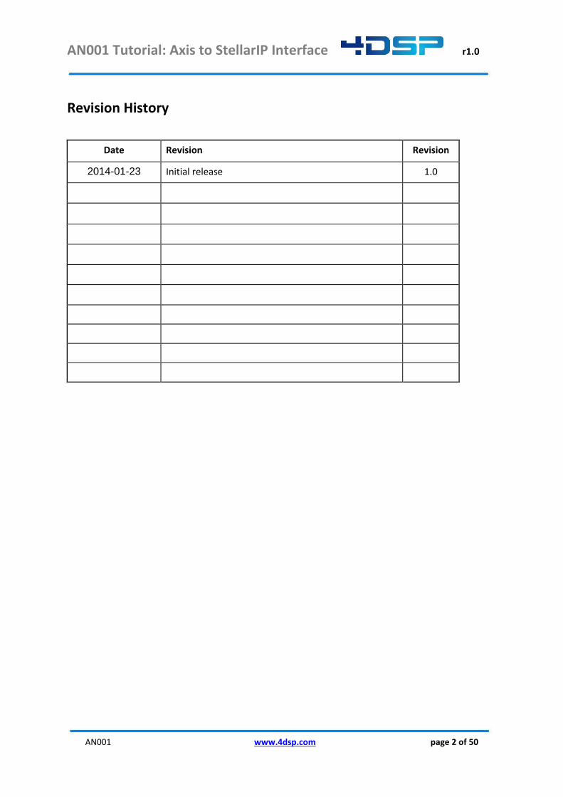
the next section, we will define the wormhole contents as follows:
Wormhole name = axis_32b_in
Wormhole direction = in
Wormhole name = axis_32b_out
Wormhole direction = out
name direction width name direction width
tvalid in 1 tvalid out 1
tdata in 32 tdata out 32
tlast in 1 tlast out 1
tuser in 32 tuser out 32
tready out 1 tready in 1
tstrb out 1 tstrb in 1
tkeep out 4 tkeep in 4
Table 1 32 bits axi stream wormhole pair
2.1.1 The following steps show how to create these two worm holes
1. Launch StellarIP
2. Go to Library in the menu and click wormhole editor.
3. Click ‘Add’

AN001 Tutorial: Axis to StellarIP Interface r1.0
AN001 www.4dsp.com page 8 of 50
4. Create the axis_32b_in wormhole. In order to add ports; fill in the port properties; name,
width and direction and click ‘Add’
5. Create the axis_32b_out wormhole
6. Close the wormhole editor
2.1.2 Creating a new star
Now that the wormholes are defined we can create the star that will wrap the FFT core.
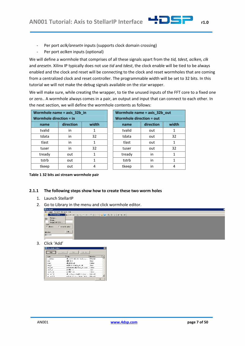
1. Click the ‘Edit’ button on the star picker window to edit the star library
AN001 Tutorial: Axis to StellarIP Interface r1.0
AN001 www.4dsp.com page 9 of 50
2. In the menu click Star->New Star and insert the name for the new star, for example
sip_xfft_wrapper, in the widow that pops-up
3. Draw a rectangle
4. Add pins to the star, each pin represents a wormhole. We will need 6 pins, 4 inputs on the
left and 2 outputs on the right.
5. After placing the pin you can double click on the pin to change its properties. For the output
pins we set the ‘left’ option and we assign the names and types: cmdclk = cmdclk_in type, rst

AN001 Tutorial: Axis to StellarIP Interface r1.0
AN001 www.4dsp.com page 10 of 50
= rstin type, data_in = axis_32b_in type, data_out = axis_32b_out type, status =
axis_32b_out type, control = axis_32b_in type.
The pin tool options dialog:
The Star symbol will look like:
6. Pressing <ctrl+s> or the save button opens the star properties window. Press the ‘Save’
button and we have created the sip_xfft_wrapper star
For this tutorial, all stars will run synchronously using the cmd_clk, generated by the
Ethernet MAC star (sip_mac_engine). Therefore we will only create stars with one single
clock input. If the FFT processing needs to be accelerated, one could choose to
implement another clock scheme. This requires stars or custom firmware blocks that
support cross clock region interfaces.

AN001 Tutorial: Axis to StellarIP Interface r1.0
AN001 www.4dsp.com page 11 of 50
2.1.3 Creating the skeleton
Now that we have created the star in StellarIP we need to create the support files as well. The easiest
way is to let StellarIP create the folder structure and vhdl wrapper files. Click the edit button in the
star picker and find the sip_xfft_wrapper star. Right click on the sip_xfft_wrapper star and click
“Generate HDL Skeleton (No Registers)”
Figure 3 FFT wrapper skeleton options
This creates the star folder structure in the library root folder. Go to “..\sip_xfft_wrapper\“. There
will be 4 folders; sip_files, isim, simulate and vhdl.
The sip_files folder has three files
- sip_xfft_wrapper.lst = this file lists the paths to all the source files that should be used during
the creation of the Xilinx ISE/VIVADO project.
- sip_xfft_wrapper.nfo = this file holds the star identification number and the version number.
Both are four digit hexadecimal values.
- sip_xfft_wrapper.vhd = this file defines the architecture of the star. This file will be modified
to instantiate the FFT core and glue logic.
The vhdl folder should be used to store all additional design files.
The simulate folder can be used to hold test bench specific files, but is not used in this tutorial.
The isim folder can be used to hold the isim project, but is not used in this tutorial.

AN001 Tutorial: Axis to StellarIP Interface r1.0
AN001 www.4dsp.com page 12 of 50
2.2 Adding the FFT IPcore
Now that we have the wrapper files available for the FFT core we can generate the IP core itself and
instantiate it in the top level wrapper vhdl file as well as adding the required files into the .LST file.
2.2.1 Generate the FFT core
1. Open the ‘CORE generator’ under Start->All Programs->Xilinx Design Tools->ISE Design Suite-
>ISE Design tools -> 64/32-bit Tools.
2. New Project and save the coregen project file to “..\sip_xfft_wrapper\”
3. Select the parts for KC705 on the pop-up window as shown in the following figure and click
‘Ok’.
4. In the IP Catalog, find the Fast Fourier Transform 8.0 and customize it by double clicking the
function.
5. Name the component as xfft_v8_0_1ch_blk_float. In this tutorial, 1 channel N-point
pipelined FFT with a block fixed point will be used.

AN001 Tutorial: Axis to StellarIP Interface r1.0
AN001 www.4dsp.com page 13 of 50
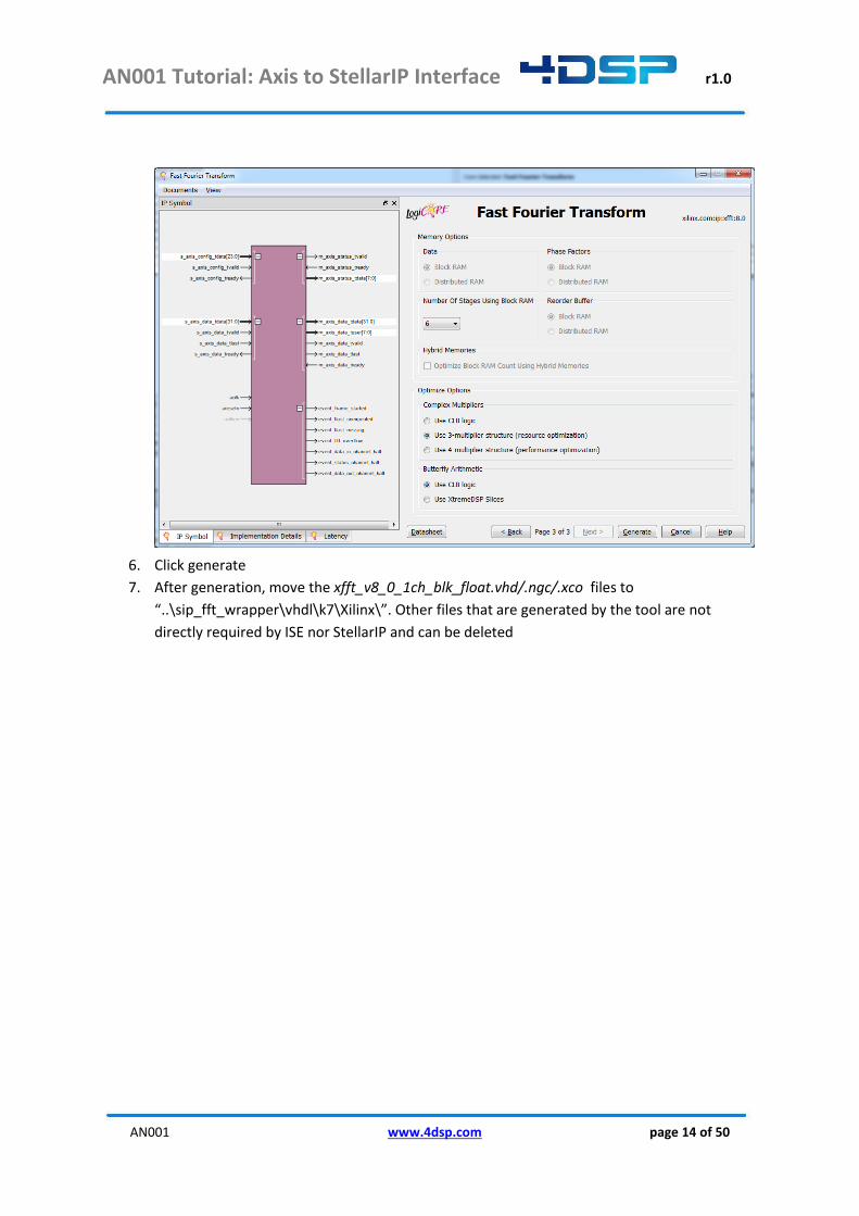
Copy the settings as shown in the following figures:
AN001 Tutorial: Axis to StellarIP Interface r1.0
AN001 www.4dsp.com page 14 of 50
6. Click generate
7. After generation, move the xfft_v8_0_1ch_blk_float.vhd/.ngc/.xco files to
“..\sip_fft_wrapper\vhdl\k7\Xilinx\”. Other files that are generated by the tool are not
directly required by ISE nor StellarIP and can be deleted

AN001 Tutorial: Axis to StellarIP Interface r1.0
AN001 www.4dsp.com page 15 of 50
2.2.2 Update the VHDL wrapper file
Declare and instantiate the FFT IP core in sip_xfft_wrapper.vhd. The connection between the FFT IP
core signals and the axis_32b_in and axis_32b_out wormhole signals have to be made as shown in
the following table.
wormhole signal connects to
wormhole signal connects to
data in
tvalid s_axis_data_tvalid
status
tvalid m_axis_status_tvalid
tdata s_axis_data_tdata
tdata[7..0] m_axis_status_tdata
tlast s_axis_data_tlast
tdata[31..8] force 0x000000
tuser not used
tlast force ‘0’
tready s_axis_data_tready
tuser force 0x00000000
tstrb force ‘0’
tready m_axis_status_tready
tkeep force 0x0
tstrb not used
tkeep not used
data out
tvalid m_axis_data_tvalid
control
tvalid s_axis_config_tvalid
tdata m_axis_data_tdata
tdata[7..0] s_axis_config_tdata
tlast m_axis_data_tlast tdata[31..8] not used
tuser m_axis_data_tuser
tlast not used
tready m_axis_data_tready
tuser not used
tstrb not used
tready s_axis_config_tready
tkeep not used
tstrb force ‘0’
tkeep force 0x0
Table 2 sip_xfft_wrapper wormhole connections
The clk and rst wormhole signals map to the FFT IP core as shown in Table 3.
wormhole signal connects to
cmdclk_in cmdclk Aclk
rst
rst_in[2] aresetn (after inverting the signal)
rst_in[1..0] not used
rst_in[31..3] not used
Table 3 sip_xfft_wrapper clk and rst wormhole connections
2.2.3 Adding the required files to the .LST file
Add the source files, located in the “..\vhdl\xilinx” folder to sip_fft_wrapper.lst using relative paths:
../vhdl/xilinx/xfft_v8_0_1ch_blk_float.xco
../vhdl/xilinx/xfft_v8_0_1ch_blk_float.vhd
../vhdl/xilinx/xfft_v8_0_1ch_blk_float.ngc
AN001 Tutorial: Axis to StellarIP Interface r1.0
AN001 www.4dsp.com page 16 of 50
3 Interface data wh_in/out to axis_32b_in/out 4DSP has chosen to standardize communication between stars as much as possible. In most cases,
data is communicated from a wh_out wormhole to a wh_in wormhole. These wormholes are defined
as 64 bits data, 1 bits data valid and 1 bit stop. On each clock cycle where the data valid is asserted,
data is transferred regardless of the status of the stop signal. However, the transmitting star is not
allowed to start sending data when the stop signal is asserted and should stop sending data within 8
clock cycles after the stop signal was asserted by the receiver.
It is not possible to interface 4DSP standard wormhole to the axis_32b wormholes directly. The main
differences between the two interfaces are:
- 4DSP standard wormhole has 64-bit data width, the AXI interface is 32-bit
- 4DSP standard output wormhole asserts data_valid when data_stop is ‘0’ and the data is valid. When the data_stop is asserted the data_valid should be de-asserted within 8 clock cycles. Valid data is transferred on each clock cycle where data_valid is asserted. The AXI protocol is different, the master side asserts tvalid when tdata is valid but waits until the slave accepts the data by asserting tready. Only when tdata and tready are asserted at the rising edge of the clock the next data word is placed on the data bus.
-
We need to create two conversion stars. A wh_in to axis_32b_out conversion star, this start receives
data from a 4DSP standard wormhole and writes it to the AXI slave. The other star is an axis_32b_in
to wh_out conversion star, receiving data from the AXI master and writes the data to a connected
4DSP standard wormhole via the wh_out output.
3.1 Creating the wh_in2axis_32b_out star
The wh_in2axis_32b_out star contains a standard 4DSP wormhole input (referred to as wh_in), the
axis_32b wormhole output (referred to as axis_32b_out) and the standard reset and cmdclk types.
Name Wormhole
data_in wh_in
data_out axis_32b_out
clk cmdclk_in
rst rst_in
Table 4 wh_in2axis_32b_out star wormholes
The main features of the star will be:
- Convert 64-bit 4DSP wormhole data width to 32-bit AXI data width
- Change the 4DSP wormhole write protocol to the AXI protocol
The implementation of this star is based on a Xilinx FIFO generated with the Core Generator.

AN001 Tutorial: Axis to StellarIP Interface r1.0
AN001 www.4dsp.com page 17 of 50
3.1.1 Create the wh_in2axis_32b_out star in stellar IP
In this subsection the steps from section 2.1.2 are repeated to create the wh_in2axis_32b_out star.
The wormhole types required for this star are already created in previous sections and available.
1. Click the edit button on the star picker window to edit the star library.
2. Choose the Star->New Star and insert the name for the new star, for example
sip_wh_in2axis_32b_out, in the widow that pops-up
3. Draw a rectangle
4. Add pins to the star, each pin represents a wormhole. We will need 5 pins, 4 inputs on the
left and 1 outputs on the right.
AN001 Tutorial: Axis to StellarIP Interface r1.0
AN001 www.4dsp.com page 18 of 50
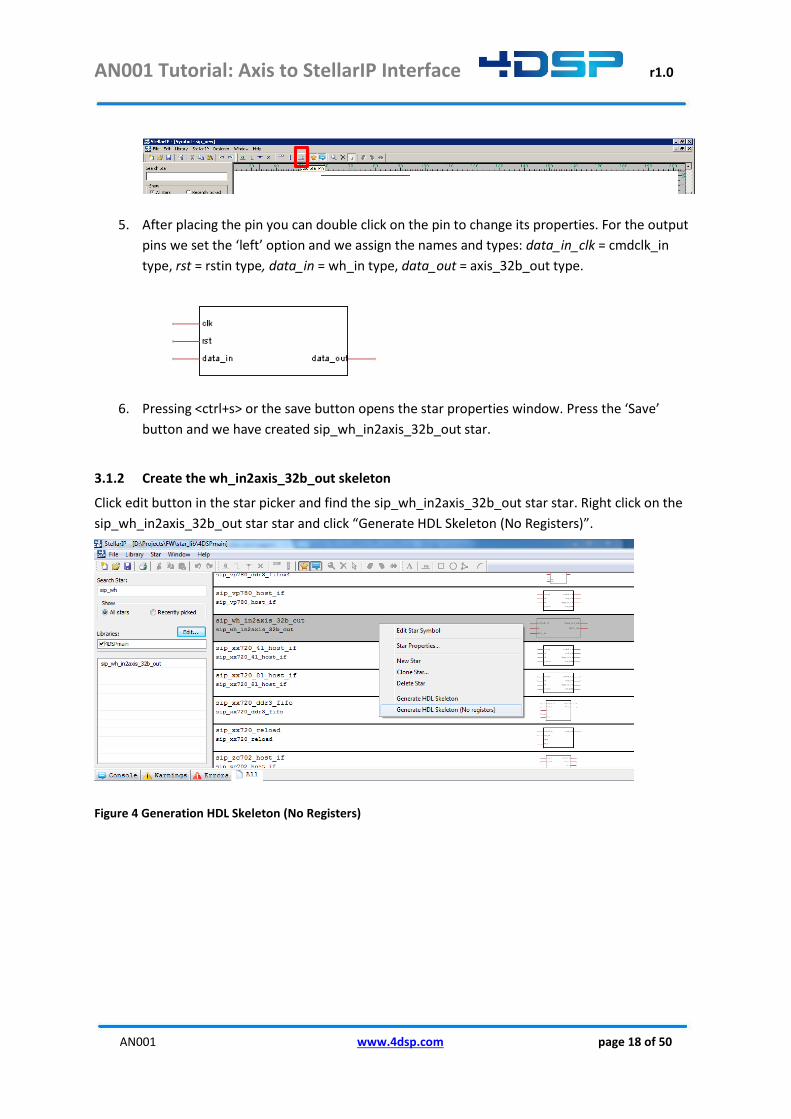
5. After placing the pin you can double click on the pin to change its properties. For the output
pins we set the ‘left’ option and we assign the names and types: data_in_clk = cmdclk_in
type, rst = rstin type, data_in = wh_in type, data_out = axis_32b_out type.
6. Pressing <ctrl+s> or the save button opens the star properties window. Press the ‘Save’
button and we have created sip_wh_in2axis_32b_out star.
3.1.2 Create the wh_in2axis_32b_out skeleton
Click edit button in the star picker and find the sip_wh_in2axis_32b_out star star. Right click on the
sip_wh_in2axis_32b_out star star and click “Generate HDL Skeleton (No Registers)”.
Figure 4 Generation HDL Skeleton (No Registers)
AN001 Tutorial: Axis to StellarIP Interface r1.0
AN001 www.4dsp.com page 19 of 50
3.1.3 Generate the Xilinx FIFO
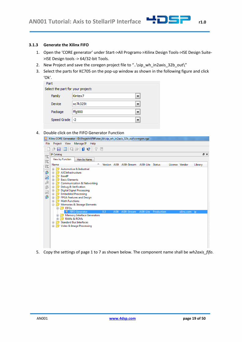
1. Open the ‘CORE generator’ under Start->All Programs->Xilinx Design Tools->ISE Design Suite-
>ISE Design tools -> 64/32-bit Tools.
2. New Project and save the coregen project file to “..\sip_wh_in2axis_32b_out\”
3. Select the parts for KC705 on the pop-up window as shown in the following figure and click
‘Ok’.
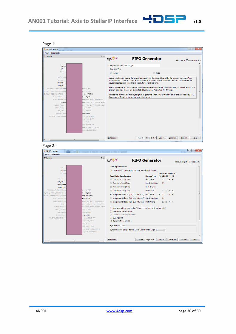
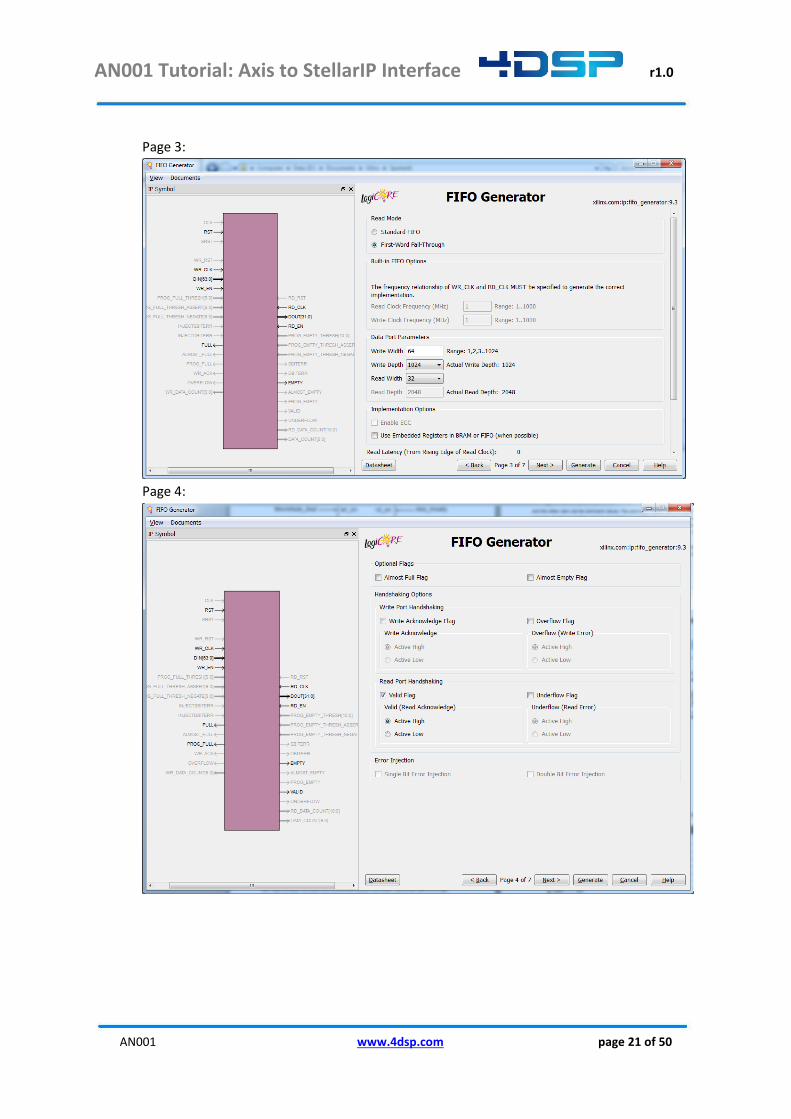
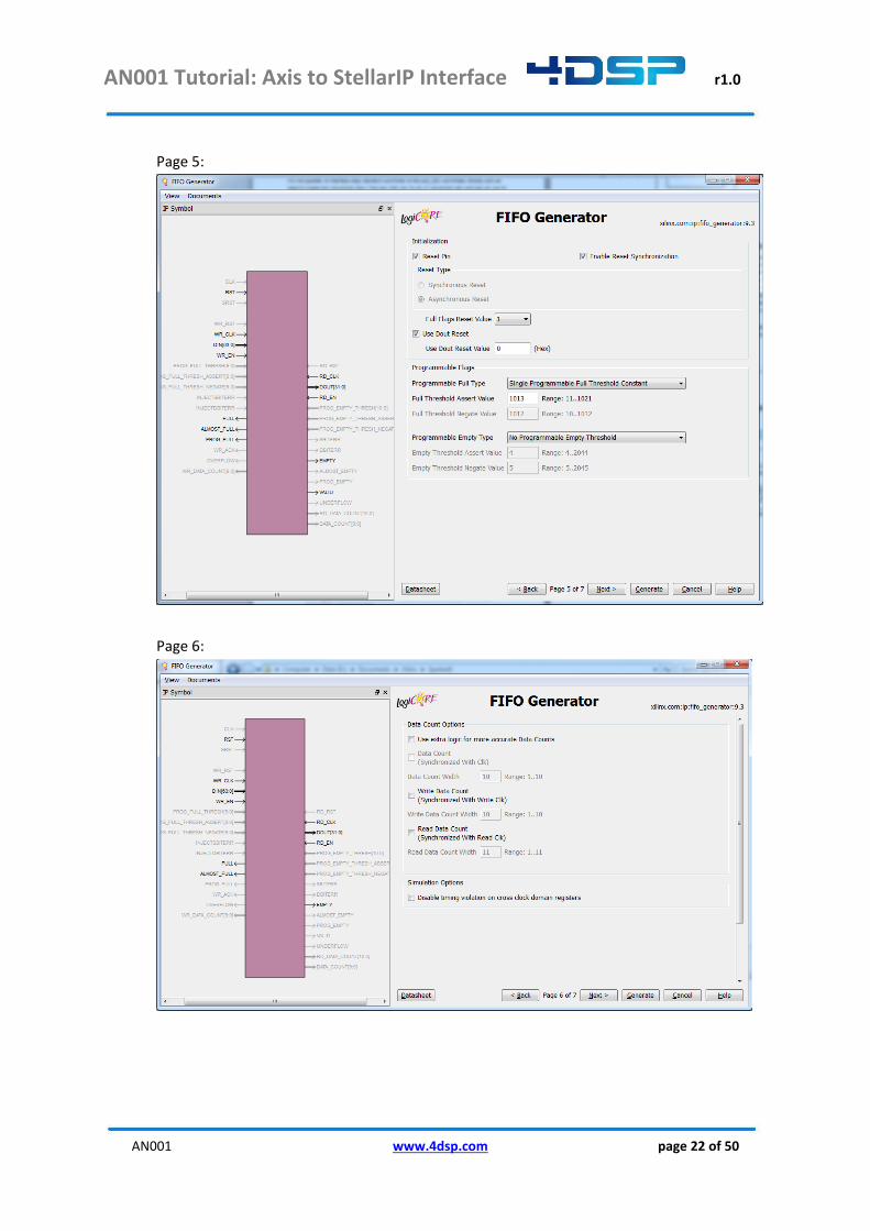
4. Double click on the FIFO Generator Function
5. Copy the settings of page 1 to 7 as shown below. The component name shall be wh2axis_fifo.
AN001 Tutorial: Axis to StellarIP Interface r1.0
AN001 www.4dsp.com page 20 of 50
Page 1:
Page 2:
AN001 Tutorial: Axis to StellarIP Interface r1.0
AN001 www.4dsp.com page 21 of 50
Page 3:
Page 4:
AN001 Tutorial: Axis to StellarIP Interface r1.0
AN001 www.4dsp.com page 22 of 50
Page 5:
Page 6:
AN001 Tutorial: Axis to StellarIP Interface r1.0
AN001 www.4dsp.com page 23 of 50
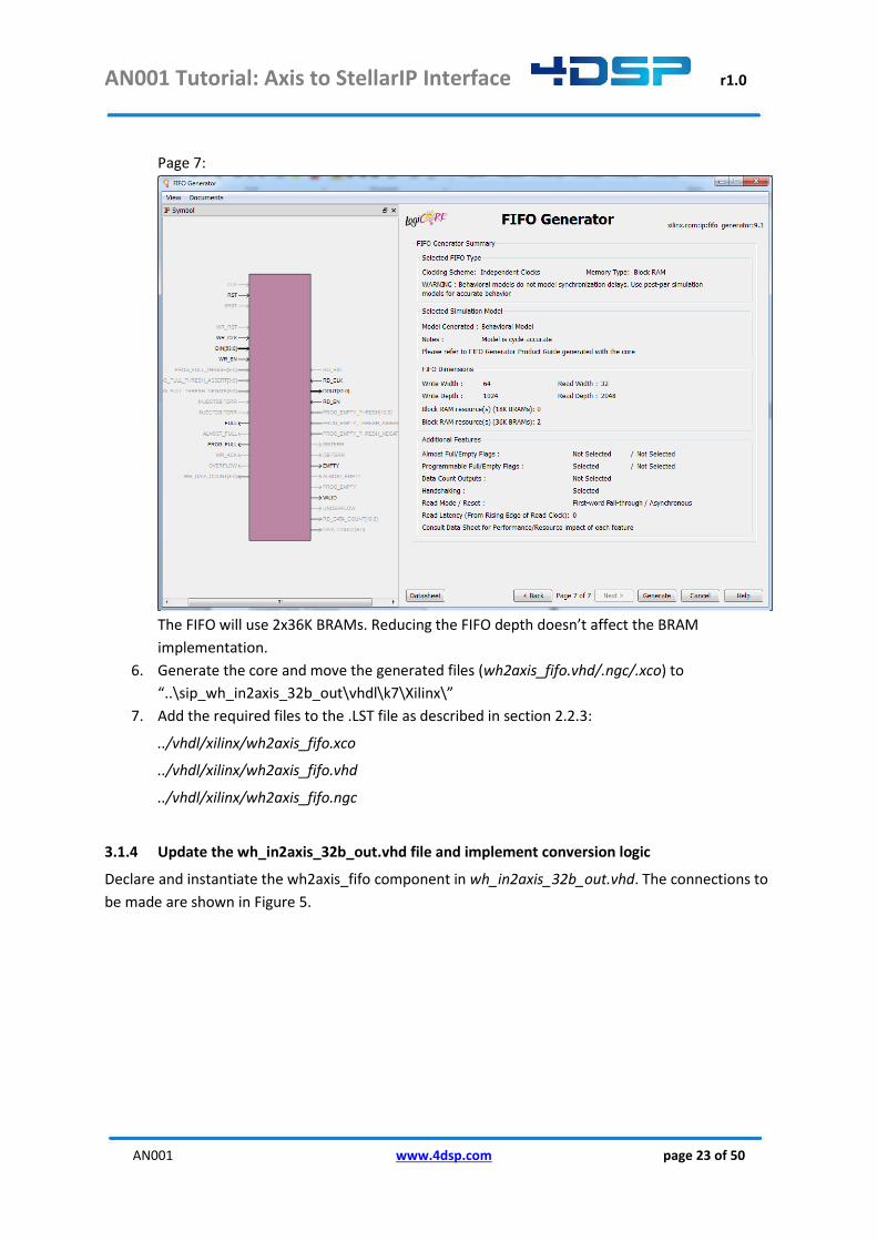
Page 7:
The FIFO will use 2x36K BRAMs. Reducing the FIFO depth doesn’t affect the BRAM
implementation.
6. Generate the core and move the generated files (wh2axis_fifo.vhd/.ngc/.xco) to
“..\sip_wh_in2axis_32b_out\vhdl\k7\Xilinx\”
7. Add the required files to the .LST file as described in section 2.2.3:
../vhdl/xilinx/wh2axis_fifo.xco
../vhdl/xilinx/wh2axis_fifo.vhd
../vhdl/xilinx/wh2axis_fifo.ngc
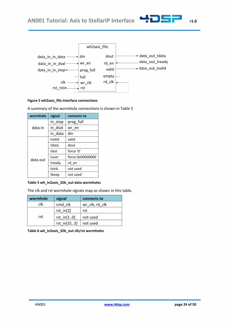
3.1.4 Update the wh_in2axis_32b_out.vhd file and implement conversion logic
Declare and instantiate the wh2axis_fifo component in wh_in2axis_32b_out.vhd. The connections to
be made are shown in Figure 5.
AN001 Tutorial: Axis to StellarIP Interface r1.0
AN001 www.4dsp.com page 24 of 50
wh2axis_fifo
rd_enwr_en
wr_clk rd_clk
din dout
prog_full valid
data_out_tdata
rst
data_out_tready
data_out_tvalid
data_in_in_data
data_in_in_dval
data_in_in_stop
rst_rstin
emptyfullclk
Figure 5 wh2axis_fifo interface connections
A summary of the wormhole connections is shown in Table 5
wormhole signal connects to
data in
in_stop prog_full
in_dval wr_en
in_data din
data out
tvalid valid
tdata dout
tlast force ‘0’
tuser force 0x00000000
tready rd_en
tstrb not used
tkeep not used
Table 5 wh_in2axis_32b_out data wormholes
The clk and rst wormhole signals map as shown in this table.
wormhole signal connects to
clk cmd_clk wr_clk, rd_clk
rst
rst_in[2] rst
rst_in[1..0] not used
rst_in[31..3] not used
Table 6 wh_in2axis_32b_out clk/rst wormholes

AN001 Tutorial: Axis to StellarIP Interface r1.0
AN001 www.4dsp.com page 25 of 50
3.2 Creating the axis_32b_in2wh_out star
Data flowing from the AXI interface to a 4DSP standard wormhole goes through this
axis_32b_in2wh_out star. A star with the following wormholes is to be created in this section.
Name Wormhole
data_in axis_32b_in
data_out wh_out
clk cmd_clkin
rst rst_in
Table 7 axis_32b_in2wh_out wormholes
The main features of the star will be:
- Convert 32-bit AXI data width to 64-bit 4DSP wormhole data width
- Change the AXI write protocol to the 4DSP standard wormhole write protocol
- Optional: the star supports clock boundary crossing
The implementation of this star is based on a Xilinx FIFO generated with the Core Generator.
3.2.1 Create the axis_32b_in2wh_out star in stellar IP
Repeat the steps of section 3.1.1 to create a star with pins: clk = cmd_clkin type, rst = rstin type,
data_in = axis_32b_in type, data_out = wh_out type.
The sip_axis_32b_in2wh_out star will look like:
Figure 6 Axis_32b_in2wh_out star symbol
3.2.2 Create the axis_32b_in2wh_out skeleton
Repeat the steps of section 3.1.2 to create the skeleton.
3.2.3 Create the axis_32b_in2wh_out conversion logic
Similar to the conversion logic of the wh_in2axis_32b_out , a FIFO is used to implement the
conversion logic. The differences between the AXIS and 4DSP data wormhole protocols require a
dedicated FIFO with some small configuration differences with respect to the wh2axis_fifo. Repeat
the steps described in section 0 with the following changes:
- Page 3: ‘Read Mode’ = Standard FIFO, ‘Write Width’ = 32, ‘Read Width’ = 64

AN001 Tutorial: Axis to StellarIP Interface r1.0
AN001 www.4dsp.com page 26 of 50
Copy the axis2wh_fifo.vhd/.ngc/.xco files to “..\sip_axis_32b_in2wh_out\vhdl\k7\Xilinx\” and add
the files to the .LST file:
../vhdl/k7/xilinx/ axis2wh_fifo.vhd
../vhdl/ k7/xilinx/ axis2wh_fifo.xco
../vhdl/ k7/xilinx/ axis2wh_fifo.ngc
Declare and instantiate the axis2wh_fifo in wh_axis_32b_in2wh_out.vhd. The connections to be
made are shown in Figure 7.
axis2wh_fifo
rd_enwr_en
wr_clk rd_clk
din dout
prog_full valid
data_out_out_data
rst
data_out_out_stop
data_out_out_dval
clk
data_in_tdata
data_in_tvalid
data_in_tready
rst_rstin
emptyfull
Figure 7 axis2wh_fifo interface connections and logic
A summary of the wormhole connections is shown in Table 8
wormhole signal connects to
data in
tvalid and with inverse of prog_full and feed into wr_en
tdata din
tlast not used
tuser not used
tready connect to inverse of prog_full
tstrb force ‘0’
tkeep force 0x0
data out
out_stop inverse and feed into rd_en
out_dval valid
out_data dout
Table 8 axis_32b_in2wh_out data wormhole connections
The clk and rst wormhole signals map as shown in this table.
wormhole signal connects to
clk cmd_clkin wr_clk, rd_clk
rst
rst_in[2] rst
rst_in[1..0] not used
rst_in[31..3] not used
Table 9 axis_32b_in2wh_out clk/rst wormhole connections
AN001 Tutorial: Axis to StellarIP Interface r1.0
AN001 www.4dsp.com page 27 of 50
4 Interface the command wormholes to axis 4DSP has defined a command distribution scheme based on a command wormhole that comprises of
64 bits vector and a valid signal. The 64 bits vector is used to send command packets. A command
packet is made from 32 bits data, 24 bits address and 4 bits command. These fields are mapped to
the 64 bits vector. Within a constellation there is always one star that will be the command master
and the other stars can be command slaves. The command master has a cmd_out wormhole that
connects directly to multiple cmd_in wormholes in parallel. The cmd_out wormhole of each star is
multiplexed to one cmd_out wormhole before it is input to the cmd_in wormhole of the command
master star. Each star is assigned a range within the 24 bits address space which allows individual
addressing of status and control registers within each star.
In order to retrieve status from the FFT core star and to send control data to the FFT core star we
need to create a conversion star between axis_32b_in/out and cmd_in/out wormholes.
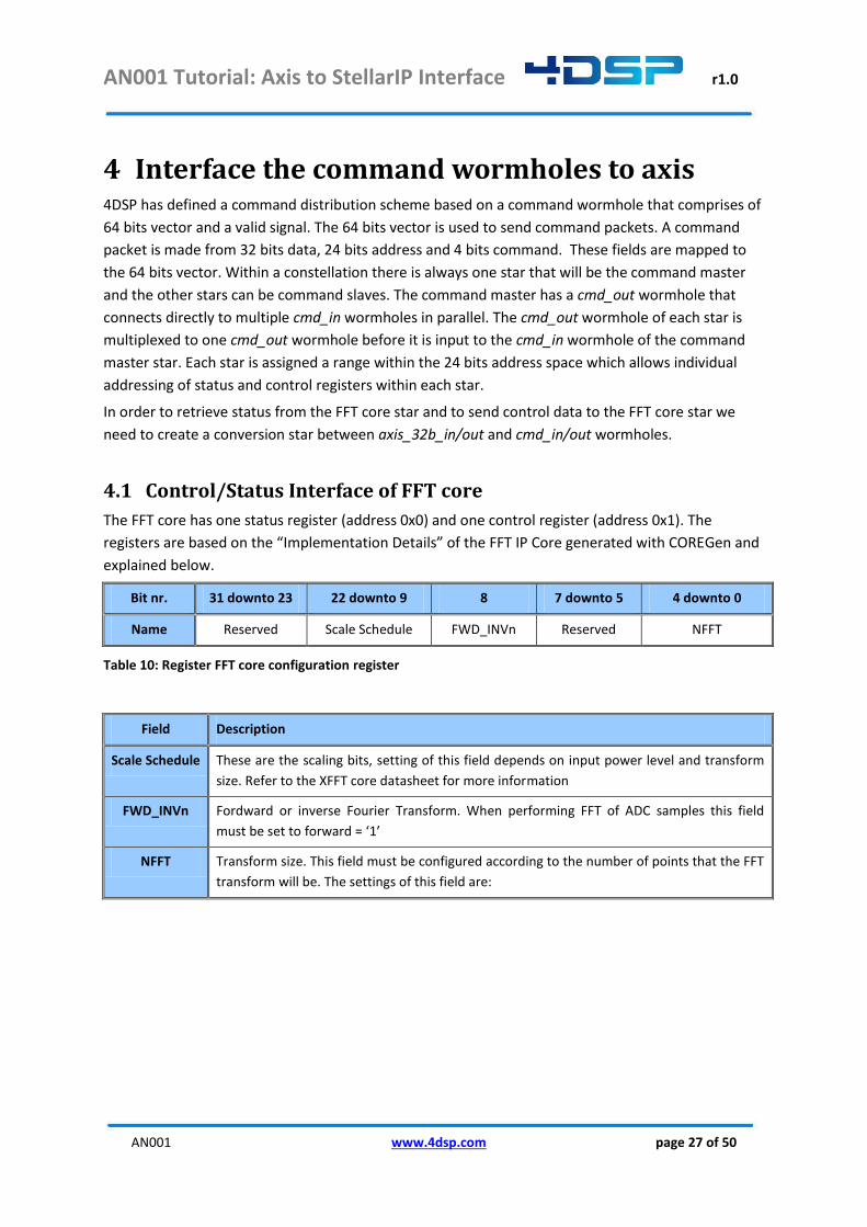
4.1 Control/Status Interface of FFT core
The FFT core has one status register (address 0x0) and one control register (address 0x1). The
registers are based on the “Implementation Details” of the FFT IP Core generated with COREGen and
explained below.
Bit nr. 31 downto 23 22 downto 9 8 7 downto 5 4 downto 0
Name Reserved Scale Schedule FWD_INVn Reserved NFFT
Table 10: Register FFT core configuration register
Field Description
Scale Schedule These are the scaling bits, setting of this field depends on input power level and transform
size. Refer to the XFFT core datasheet for more information
FWD_INVn Fordward or inverse Fourier Transform. When performing FFT of ADC samples this field
must be set to forward = ‘1’
NFFT Transform size. This field must be configured according to the number of points that the FFT
transform will be. The settings of this field are:

AN001 Tutorial: Axis to StellarIP Interface r1.0
AN001 www.4dsp.com page 28 of 50
Field Description
Table 11: FFT core configuration field description
This status register implements a single status bit:
Bit nr. 31 downto 1 0
Name Reserved OVFLO
Table 12 FFT core status field
This is the overflow indicator and is set to ‘1’ in case an overflow has occurred in a single FFT block of
size NFFT. An overflow might occur when the scaling schedule is set incorrectly or the input power is
too high.
The control register is accessed by writing a value on the control AXIS input port. Status is written to
the status AXIS output port.
4.2 Creating the cmd2axis_32b star
The cmd2axis_32b star must be created with the wormholes defined in Table 13.
Name Type
cmd_in cmd_in
cmd_out cmd_out
cmdclk_in cmdclk_in
rst rst_in
axis_32b_out axis_32b_out
axis_32b_in axis_32b_in
Table 13 cmd2axis_32b wormholes
This star implements two registers on the StellarIP register map. A write to register at offset 0 will
translate into a write on the axis_32b_out wormhole. The data from the command bus is mapped
directly on the 32 bits axis data bus. In our design example the FFT core will only receive the lower 24
bits as it does not connect the upper 8 bits.

AN001 Tutorial: Axis to StellarIP Interface r1.0
AN001 www.4dsp.com page 29 of 50
For the status we can choose two implementations
1) We implement a FIFO between the axis_32b_in wormhole to store status words that are
received. Each read from address offset 1 will then return a word from the FIFO. This is only
useful if the status will be read constantly and if it is important to keep track the status for
each frame.
2) We implement a counter that increments each time the overflow bit was set. We will clear
the counter on each read from register offset 1.
For this tutorial the second option will be used. We understand there is little value in this application
but it serves well as an example.
4.2.1 Create the cmd2axis_32b star in stellar IP
The star will be connected to the 4DSP CMD wormholes and requires a generic start and stop
address. By enabling this option, StellarIP defines the start and stop address automatically as such
that it will not conflict with any other star’s CMD wormhole address ranges. To enable these
generics, the star (required ports shown below) can be created in the similar way as previous ones,
but when saving the star, one field must be edited in the “Star Properties” window:
1. Go to “Library Star Properties -> Generic” and click “Add”.
2. Select to top one and confirm with ‘Ok’:
AN001 Tutorial: Axis to StellarIP Interface r1.0
AN001 www.4dsp.com page 30 of 50
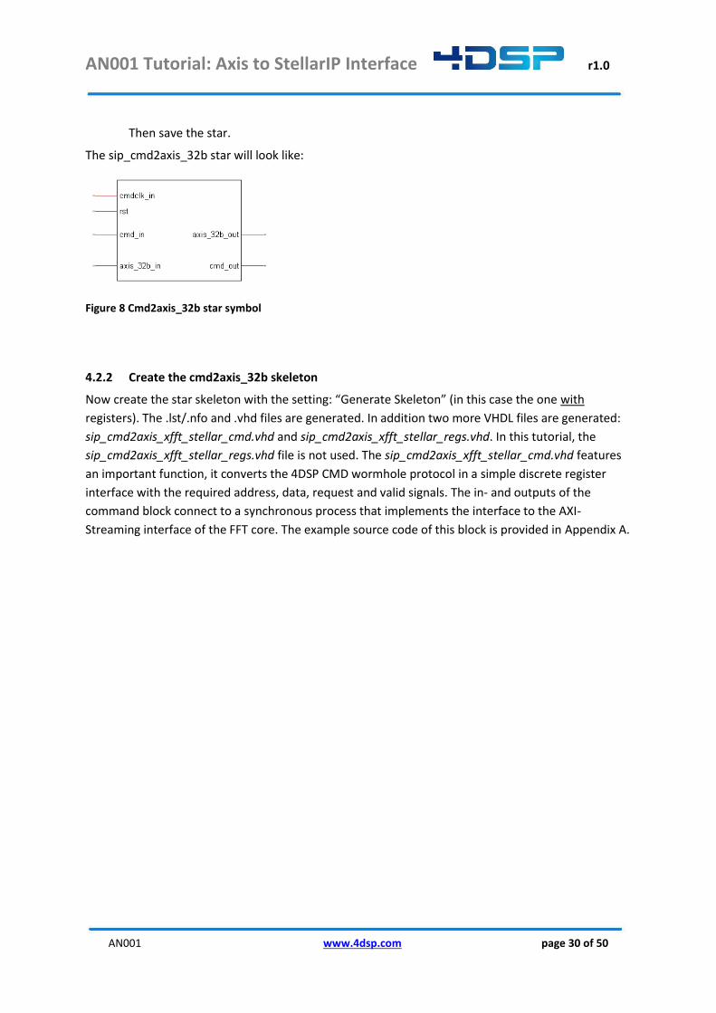
Then save the star.
The sip_cmd2axis_32b star will look like:
Figure 8 Cmd2axis_32b star symbol
4.2.2 Create the cmd2axis_32b skeleton
Now create the star skeleton with the setting: “Generate Skeleton” (in this case the one with
registers). The .lst/.nfo and .vhd files are generated. In addition two more VHDL files are generated:
sip_cmd2axis_xfft_stellar_cmd.vhd and sip_cmd2axis_xfft_stellar_regs.vhd. In this tutorial, the
sip_cmd2axis_xfft_stellar_regs.vhd file is not used. The sip_cmd2axis_xfft_stellar_cmd.vhd features
an important function, it converts the 4DSP CMD wormhole protocol in a simple discrete register
interface with the required address, data, request and valid signals. The in- and outputs of the
command block connect to a synchronous process that implements the interface to the AXI-
Streaming interface of the FFT core. The example source code of this block is provided in Appendix A.

AN001 Tutorial: Axis to StellarIP Interface r1.0
AN001 www.4dsp.com page 31 of 50
5 Data formatter The FFT core expects the input data to be 16 bits, 2s complement complex data mapped to 32 bits
data bus. In case only real data is input the imaginary part of the data should be all zeros. The
FMC104 star maps the data from each ADC on a 64 bits wh_out wormhole. The 14 bits data, is 2’s
complement, sign extended to 16 bits and then de-multiplexed to have 4 samples on 64 bits before it
is transmitted to other stars. We have two options:
1) We create a data formatter that takes a wh_in and and for each 64 bits sample it will output
two 64 bits samples. The data on the output will be as follows
1st clock cycle 2nd clock cycle
data_out[15..0] data_in[15..0] data_out[15..0] data_in[47..32]
data_out[31..16] 0x0000 data_out[31..16] 0x0000
data_out[47..32] data_in[31..16] data_out[47..32] data_in[63..48]
data_out[63..48] 0x0000 data_out[63..48] 0x0000
To cope with the data rate difference it is required to use a FIFO inside the star.
2) The other option is to create a star with an axis_32b_in and an axis_32b_out wormhole. For
each 32 bits input sample it will output two 32 bit output samples. The data on the output
will be as follows
1st clock cycle 2nd clock cycle
data_out[15..0] data_in[15..0] data_out[15..0] data_in[31..16]
data_out[31..16] 0x0000 data_out[31..16] 0x0000
Because of the nature of the AXI stream protocol this could be implemented without FIFO.
Within this tutorial we have chosen to implement the second option. The star will have the interfaces
shown in the table below.
Name Wormhole
clk cmdclk_in
rst rst_in
axis_32b_out axis_32b_out
axis_32b_in axis_32b_in
Table 14 axis_32b_real2complex star wormholes
AN001 Tutorial: Axis to StellarIP Interface r1.0
AN001 www.4dsp.com page 32 of 50
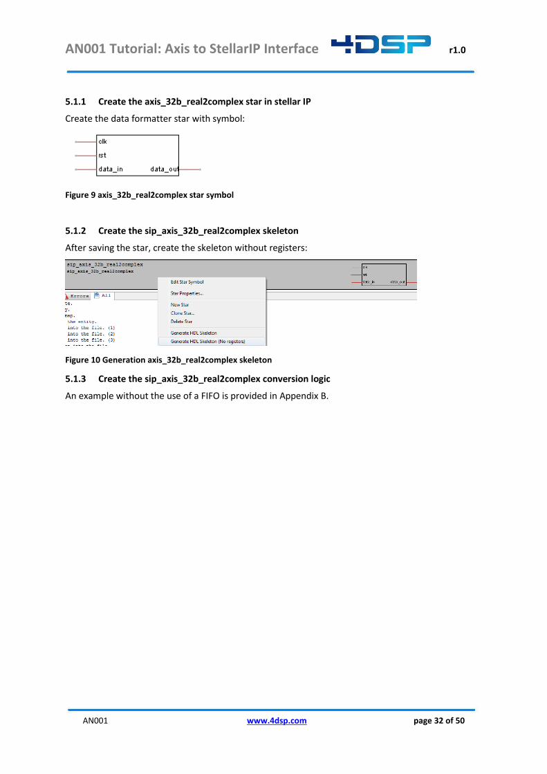
5.1.1 Create the axis_32b_real2complex star in stellar IP
Create the data formatter star with symbol:
Figure 9 axis_32b_real2complex star symbol
5.1.2 Create the sip_axis_32b_real2complex skeleton
After saving the star, create the skeleton without registers:
Figure 10 Generation axis_32b_real2complex skeleton
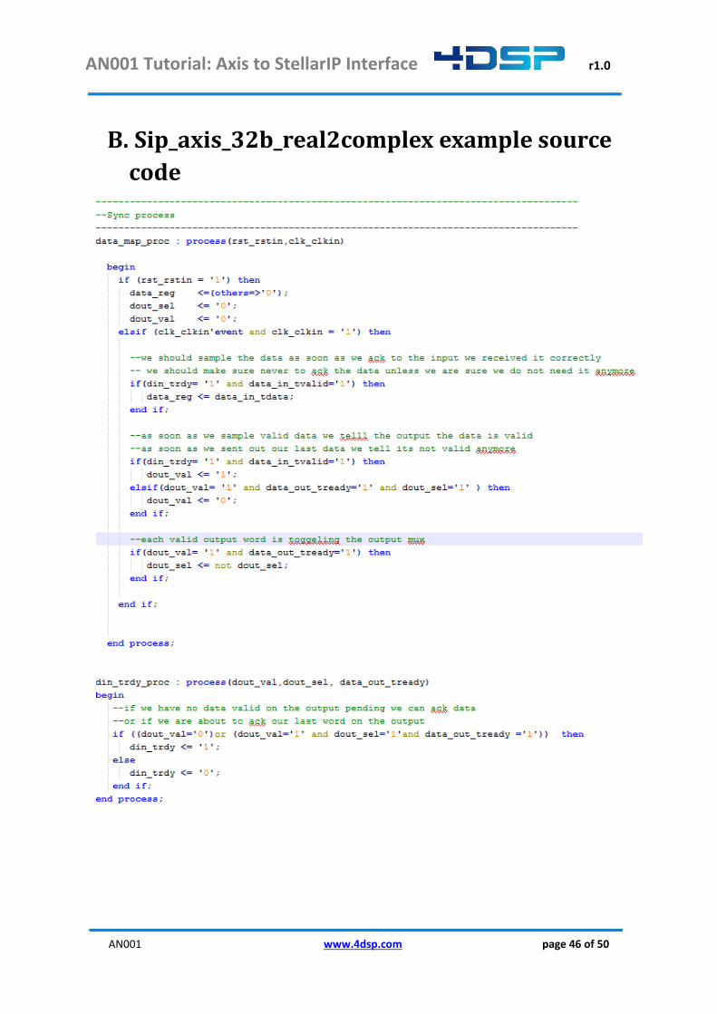
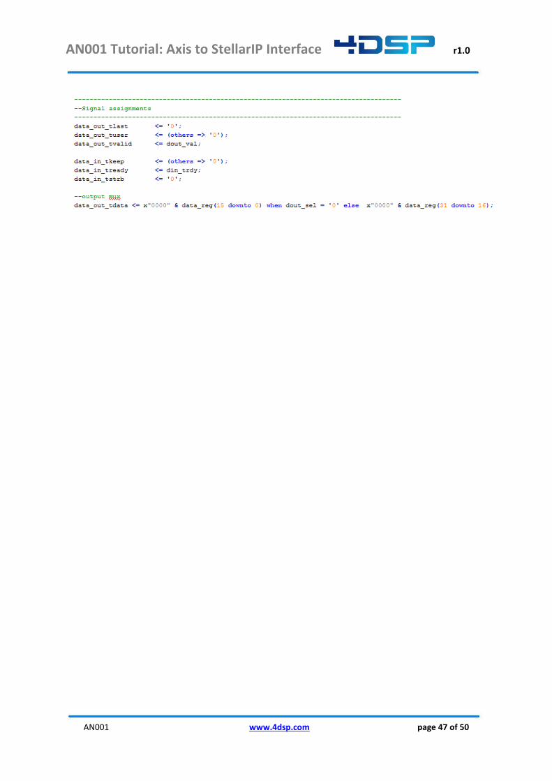
5.1.3 Create the sip_axis_32b_real2complex conversion logic
An example without the use of a FIFO is provided in Appendix B.
AN001 Tutorial: Axis to StellarIP Interface r1.0
AN001 www.4dsp.com page 33 of 50
6 Generate a Constellation This section describes the steps that one could follow to generate a new constellation from scratch. It
is also possible to clone an existing constellation; this is not part of this tutorial.
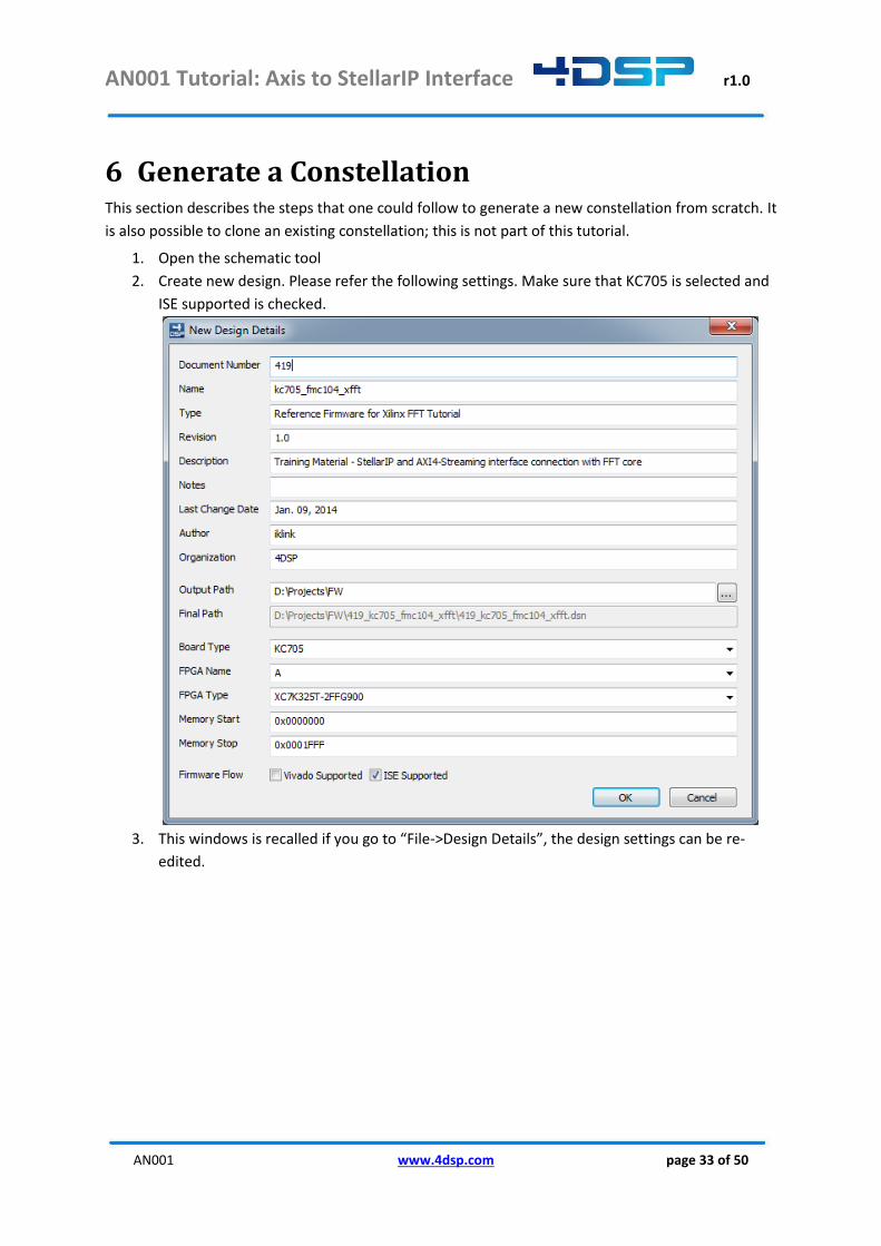
1. Open the schematic tool
2. Create new design. Please refer the following settings. Make sure that KC705 is selected and
ISE supported is checked.
3. This windows is recalled if you go to “File->Design Details”, the design settings can be re-
edited.

AN001 Tutorial: Axis to StellarIP Interface r1.0
AN001 www.4dsp.com page 34 of 50
4. Go to Stellar IP in the menu and open settings. Make sure that Xilinx ISE is enabled and ISE
binary path is correct.
5. From the star navigator on the left, stars can be added to the design. Add stars required for
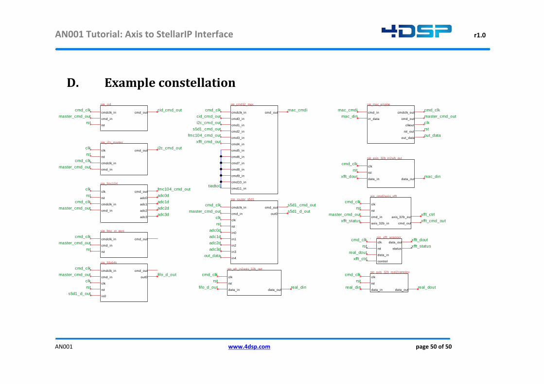
the design and connect the pins. Instead of drawing the data path, labels can be used.
Right clicking on the star symbol shows the possible actions in the context menu. The
example of the constellation is shown in Appendix D.
6. Open the completed tutorial design.
tiedto0 label is a reserved label for StellarIP to connect an input to ground.
AN001 Tutorial: Axis to StellarIP Interface r1.0
AN001 www.4dsp.com page 35 of 50
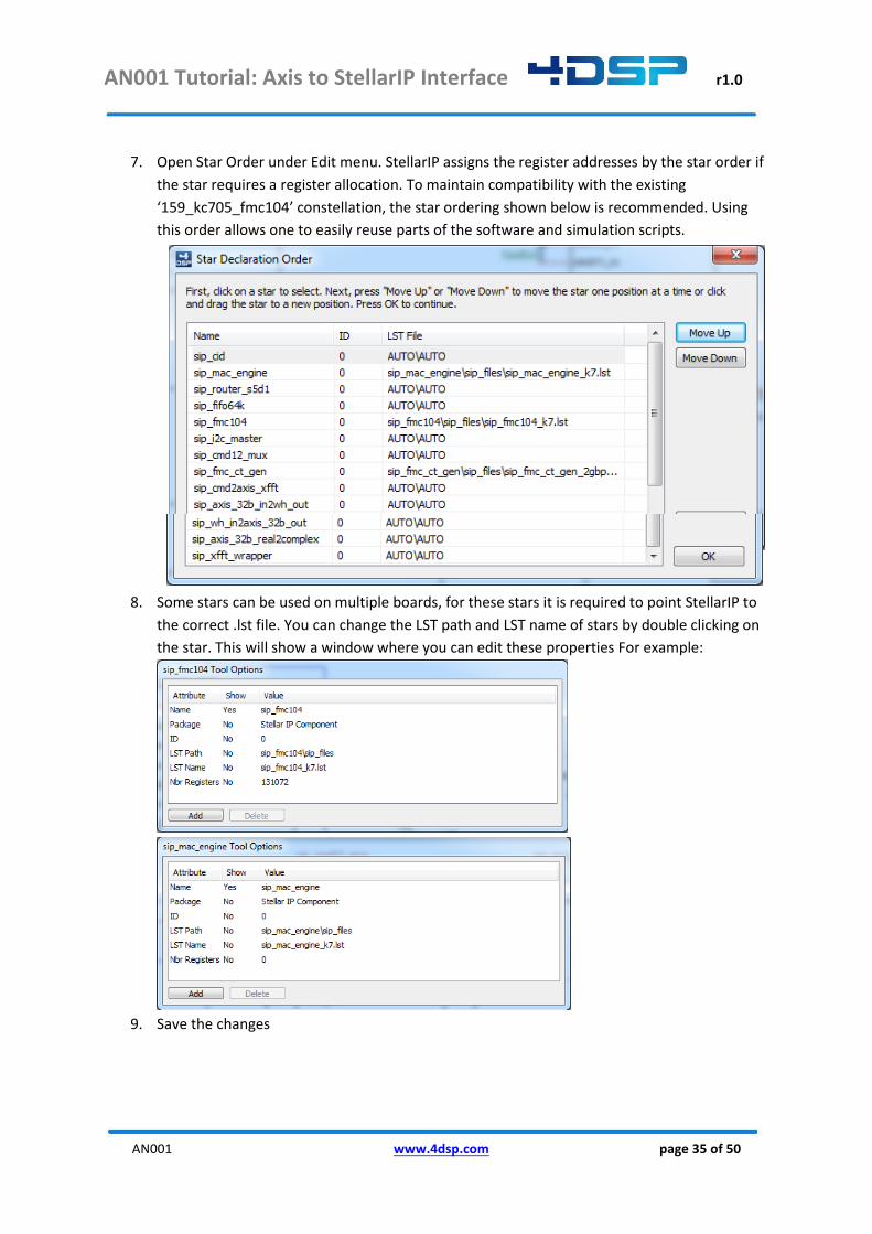
7. Open Star Order under Edit menu. StellarIP assigns the register addresses by the star order if
the star requires a register allocation. To maintain compatibility with the existing
‘159_kc705_fmc104’ constellation, the star ordering shown below is recommended. Using
this order allows one to easily reuse parts of the software and simulation scripts.
8. Some stars can be used on multiple boards, for these stars it is required to point StellarIP to
the correct .lst file. You can change the LST path and LST name of stars by double clicking on
the star. This will show a window where you can edit these properties For example:
9. Save the changes

AN001 Tutorial: Axis to StellarIP Interface r1.0
AN001 www.4dsp.com page 36 of 50
7 Generate an ISE Project and Programming File This section briefly describes the steps to generate the ISE project and compile the design.
1. In StellarIP, open the completed tutorial design. StellarIP automatically gathers the
information in the design file and can generate the ISE Project with all required files. Go to
StellarIP in the menu and click “Generate” (or use ctrl+g).
2. The console window reports the StellarIP process. If there’s an error, it reports possible
issues/errors. By changing the Global System Verbosity (in “StellarIP -> Settings”, or F11),
more detailed reports can be generated. Some of the errors can be found in the trouble
shooting section at the end of this document.
3. Go to the output folder under the constellation folder:
”../419_kc705_fmc104_xfft/output/kc705_fmc104_xfft/”. The ISE project folder is generated
there. Open the “kc705_fmc104_xfft.xise”. Click the top vhdl module and run “Generate
Programming File”.
4. After the complete compilation, verify that there are no errors or timing violations.

AN001 Tutorial: Axis to StellarIP Interface r1.0
AN001 www.4dsp.com page 37 of 50
8 Software Application To go through this section, it is required to have Visual Studio 2012 installed. If not executed yet,
follow the steps that are required to use this software, described in the 4FM Getting Started Guide.
1. In Visual Studio 2012, open the project “..\4dsp\FMC Board Support
Package\Refs\Software\FMC10x\Fmc10xAPP.vcxproj”
2. Open “fmc10xids.h” All constellations that are supported by this application are defined
here. The Constellation for this tutorial was set to 419 in Section 0. To support this ID add the
following line.
#define CONSTELLATION_ID_KC705_FMC104_XFFT 0x1A3
3. Open “Libs/FMC10x/Impls/fmc10x.cpp” and go to the switch case that configures the IO
delay controllers. The configuration of the delay controllers should be the same as per
CONSTELLATION_ID_KC705_FMC104. Add
case CONSTELLATION_ID_KC705_FMC104_XFFT:
To the CONSTELLATION_ID_KC705_FMC104 case.
4. Open “Libs/FMC10x/Impls/fmc10x_clocktree.cpp” and add case CONSTELLATION_ID_KC705_FMC104_XFFT:
To the CONSTELLATION_ID_KC705_FMC104 case of the switch.
5. Open “main.cpp” and add a CMD2AXI_XFFT_ID. Assign to this the value of the star ID. In
order to find the star ID, go to “sip_cmd2axis_xfft/sip_files” and open
“sip_cmd2axis_xfft.nfo” file.
#define CMD2AXI_XFFT_ID 0xE2
6. Within “main.cpp”, find the variable set up for given constellation IDs. FMC10xAPP supports
4DSP FMC products such that FMC103, FMC104, FMC107 and FMC108. Add the following
case. case CONSTELLATION_ID_KC705_FMC104_XFFT :
deviceFW = "FMC104 Xilinx FFT on KC705\n"; modeFMC104 = 1; FMCConstID = FMC104_ID; FMCnbrch = 4; routerID = ROUTER_S5D1_ID; modeKC705 = 1;
break;
7. cid_getstaroffset() reads the star offset which represent the star register address. The star offset read functions are followed by the constellation ID case statements. Add the following function call. (define AddrSipCmd2AxiXfft as uint32_t) if(cid_getstaroffset(CMD2AXI_XFFT_ID, &AddrSipCmd2AxiXfft, &size)!=SIP_CID_ERR_OK) {
printf("Could not obtain address for star type %d, exiting\n", CMD2AXI_XFFT_ID);
sipif_free();
AN001 Tutorial: Axis to StellarIP Interface r1.0
AN001 www.4dsp.com page 38 of 50
return -7;
}
8. The FFT core processes real samples and outputs complex samples. In “main.cpp”, the
BurstSize defines the number of samples captured by the ADC interface and transmitted to
the FFT core. The pInData memory is allocated to store the data samples. This memory is
allocated in bytes. For this constellation it is necessary to allocate 4 times the BurstSize.
Change the memory allocation to: unsigned char *pInData = (unsigned char *)_aligned_malloc(4*BurstSize, 4096);
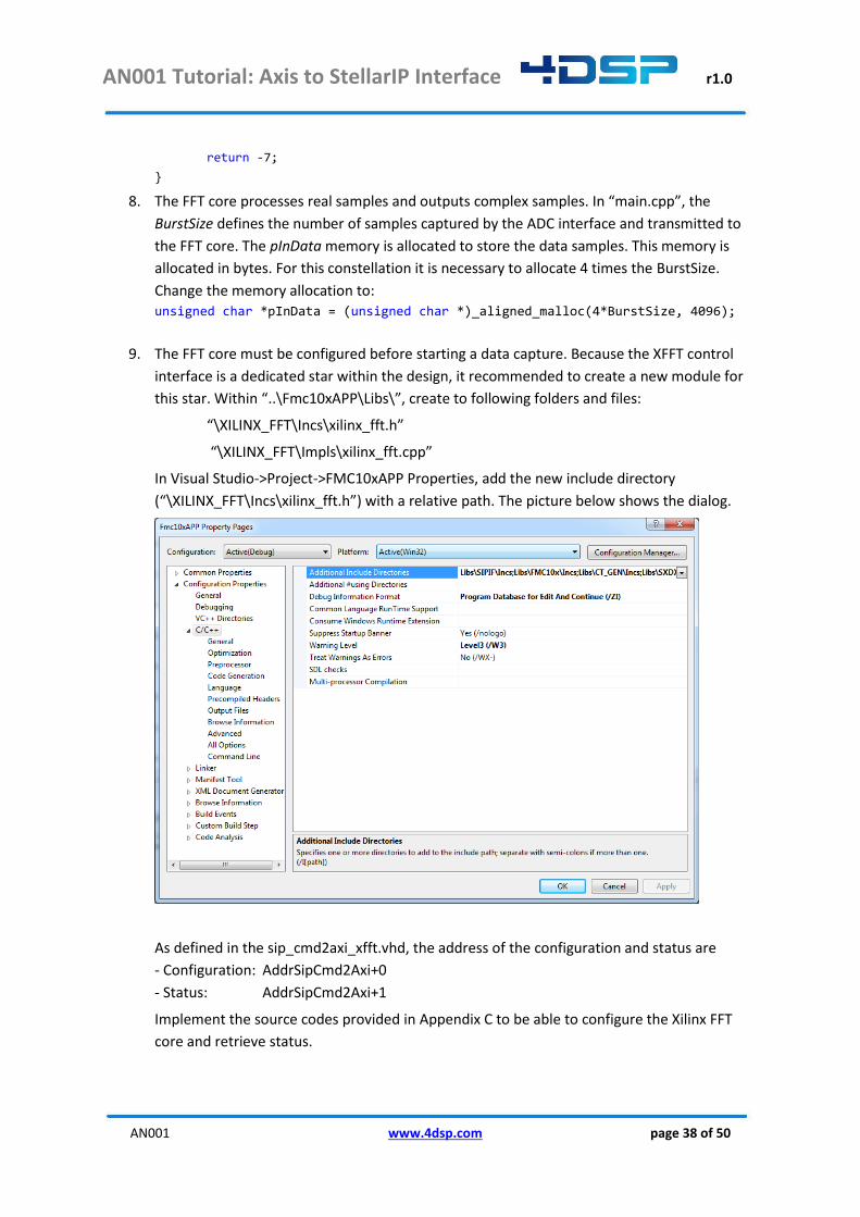
9. The FFT core must be configured before starting a data capture. Because the XFFT control
interface is a dedicated star within the design, it recommended to create a new module for
this star. Within “..\Fmc10xAPP\Libs\”, create to following folders and files:
“\XILINX_FFT\Incs\xilinx_fft.h”
“\XILINX_FFT\Impls\xilinx_fft.cpp”
In Visual Studio->Project->FMC10xAPP Properties, add the new include directory
(“\XILINX_FFT\Incs\xilinx_fft.h”) with a relative path. The picture below shows the dialog.
As defined in the sip_cmd2axi_xfft.vhd, the address of the configuration and status are
- Configuration: AddrSipCmd2Axi+0
- Status: AddrSipCmd2Axi+1
Implement the source codes provided in Appendix C to be able to configure the Xilinx FFT
core and retrieve status.
AN001 Tutorial: Axis to StellarIP Interface r1.0
AN001 www.4dsp.com page 39 of 50
10. In “main.cpp”, include the header file created in previous step #include "xilinx_fft.h"
Further down the file, before the data capture for the four channels is initiated, configure the
FFT core by adding the following source code (calling the function in the xilinx_fft module) :
/////////////////////////////////////////////////////////////////////////////// // Configure Xilinx FFT Core if (cid_getconstellationid()==CONSTELLATION_ID_KC705_FMC104_XFFT) { int scaling = 0x7777;
if(xfft_configure(AddrSipCmd2AxiXfft, true, scaling, BurstSize)!=SIP_XFFT_ERR_OK){
printf("Could not configure Xilinx FFT Core\n"); printf("Xilinx FFT is set to illegal amount of points: %d\n",BurstSize); printf("BurstSize must be set with a power of 2, range 64 to 8192\n");
sipif_free(); }else{ printf("--------------------------------------\n"); printf("Xilinx FFT set to %d points\n",BurstSize); printf("--------------------------------------\n"); }
}
11. In “main.cpp”, go to the part where data is read from the pipe, this is done within the for
loop:
// loop here as many times we have channels to grab samples from for(int32_t i = 0; i < FMCnbrch; i++) {
Double the amount of bytes have to be read from the pipe for the FFT constellation. Change:
printf("Retrieve %d samples from ADC%d\n", BurstSize,i); if(sipif_readdata (pInData, 2*BurstSize)!=SIPIF_ERR_OK) { printf("Could not communicate with device %d\n", devIdx); sipif_free(); _aligned_free(pInData); return -24;
To:
if (cid_getconstellationid()!=CONSTELLATION_ID_KC705_FMC104_XFFT) { printf("Retrieve %d samples from ADC%d\n", BurstSize,i); // Real samples only if(sipif_readdata (pInData, 2*BurstSize)!=SIPIF_ERR_OK) { printf("Could not communicate with device %d\n", devIdx); sipif_free(); _aligned_free(pInData); return -24; } } else { printf("Retrieve %d point FFT from ADC%d\n", BurstSize,i); // Complex samples from FFT core if(sipif_readdata (pInData, 4*BurstSize)!=SIPIF_ERR_OK) { printf("Could not communicate with device %d\n", devIdx);
AN001 Tutorial: Axis to StellarIP Interface r1.0
AN001 www.4dsp.com page 40 of 50
sipif_free(); _aligned_free(pInData); return -24; }
}
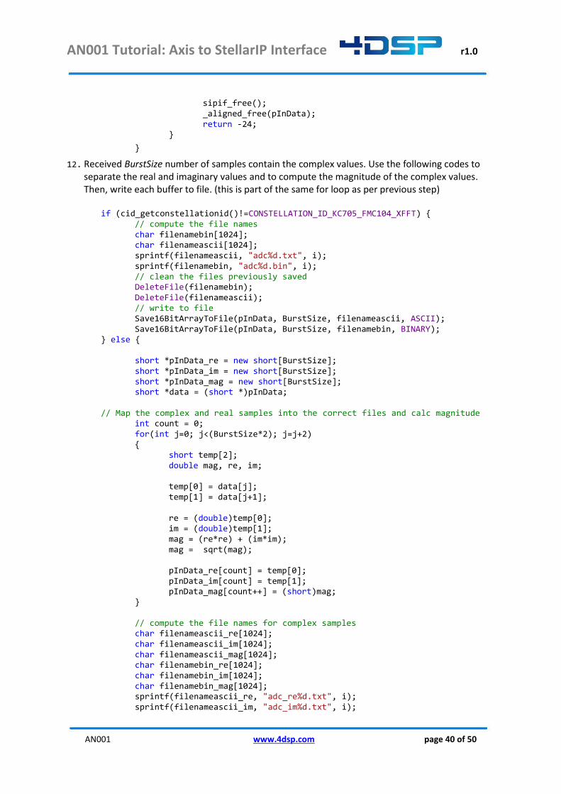
12. Received BurstSize number of samples contain the complex values. Use the following codes to separate the real and imaginary values and to compute the magnitude of the complex values. Then, write each buffer to file. (this is part of the same for loop as per previous step) if (cid_getconstellationid()!=CONSTELLATION_ID_KC705_FMC104_XFFT) {
// compute the file names char filenamebin[1024]; char filenameascii[1024]; sprintf(filenameascii, "adc%d.txt", i); sprintf(filenamebin, "adc%d.bin", i); // clean the files previously saved DeleteFile(filenamebin); DeleteFile(filenameascii); // write to file Save16BitArrayToFile(pInData, BurstSize, filenameascii, ASCII); Save16BitArrayToFile(pInData, BurstSize, filenamebin, BINARY); } else { short *pInData_re = new short[BurstSize]; short *pInData_im = new short[BurstSize]; short *pInData_mag = new short[BurstSize]; short *data = (short *)pInData; // Map the complex and real samples into the correct files and calc magnitude int count = 0; for(int j=0; j<(BurstSize*2); j=j+2) { short temp[2]; double mag, re, im; temp[0] = data[j]; temp[1] = data[j+1]; re = (double)temp[0]; im = (double)temp[1]; mag = (re*re) + (im*im); mag = sqrt(mag); pInData_re[count] = temp[0]; pInData_im[count] = temp[1]; pInData_mag[count++] = (short)mag; } // compute the file names for complex samples char filenameascii_re[1024]; char filenameascii_im[1024]; char filenameascii_mag[1024]; char filenamebin_re[1024]; char filenamebin_im[1024]; char filenamebin_mag[1024]; sprintf(filenameascii_re, "adc_re%d.txt", i); sprintf(filenameascii_im, "adc_im%d.txt", i);

AN001 Tutorial: Axis to StellarIP Interface r1.0
AN001 www.4dsp.com page 41 of 50
sprintf(filenameascii_mag, "adc_mag%d.txt", i); sprintf(filenamebin_re, "adc_re%d.bin", i); sprintf(filenamebin_im, "adc_im%d.bin", i); sprintf(filenamebin_mag, "adc_mag%d.bin", i); // clean the files previously saved DeleteFile(filenameascii_re); DeleteFile(filenameascii_im); DeleteFile(filenameascii_mag); DeleteFile(filenamebin_re); DeleteFile(filenamebin_im); DeleteFile(filenamebin_mag); // Save output to files Save16BitArrayToFile(pInData_re, BurstSize, filenameascii_re, ASCII); Save16BitArrayToFile(pInData_im, BurstSize, filenameascii_im, ASCII); Save16BitArrayToFile(pInData_mag, BurstSize, filenameascii_mag, ASCII); Save16BitArrayToFile(pInData_re, BurstSize, filenamebin_re, BINARY); Save16BitArrayToFile(pInData_im, BurstSize, filenamebin_im, BINARY); Save16BitArrayToFile(pInData_mag, BurstSize, filenamebin_mag, BINARY); }
13. Within the same for loop, after the data is read from the pipe, read the status of the XFFT
overflow flag to see whether the input power was too high or the scaling was set incorrectly.
Add the following source code (this source code calls the xfft_getstatus function inside the
xilinx_fft module):
// Retrieve overflow status of XFFT core if (cid_getconstellationid()==CONSTELLATION_ID_KC705_FMC104_XFFT) { uint32_t ovflow_cnt = 0;
if(xfft_getstatus(AddrSipCmd2AxiXfft, &ovflow_cnt)!=SIP_XFFT_ERR_OK){
printf("Could not retrieve overflow status from Xilinx FFT Core\n ");
sipif_free(); }else{
printf("FFT Scaling overflow count of ADC%d:%d \n\n", i, ovflow_cnt);
} }
14. Text files for real, imaginary and magnitude values can be found in the software folder. You
can further implement the software to generate the FFT plot or use other application.
15. Compile the project. The executable is generated in “..\4dsp\FMC Board Support
Package\Refs\Software\FMC10x\Debug”. Follow the steps described in the 4FM Getting
Started Guide to test the application.
AN001 Tutorial: Axis to StellarIP Interface r1.0
AN001 www.4dsp.com page 42 of 50
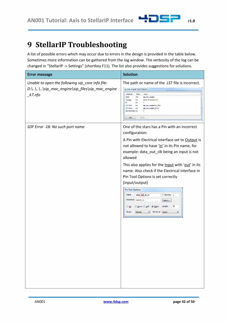
9 StellarIP Troubleshooting A list of possible errors which may occur due to errors in the design is provided in the table below.
Sometimes more information can be gathered from the log window. The verbosity of the log can be
changed in “StellarIP -> Settings” (shortkey F11). The list also provides suggestions for solutions.
Error message Solution
Unable to open the following sip_core info file:
D:\..\..\..\sip_mac_engine\sip_files\sip_mac_engine
_k7.nfo
The path or name of the .LST file is incorrect.
SDF Error -18: No such port name One of the stars has a Pin with an incorrect
configuration:
A Pin with Electrical interface set to Output is
not allowed to have ‘in’ in its Pin name, for
example: data_out_clk being an input is not
allowed
This also applies for the Input with ‘out’ in its
name. Also check if the Electrical interface in
Pin Tool Options is set correctly
(input/output)
AN001 Tutorial: Axis to StellarIP Interface r1.0
AN001 www.4dsp.com page 43 of 50
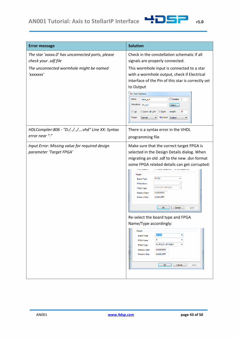
Error message Solution
The star 'xxxxx.0' has unconnected ports, please
check your .sdf file
The unconnected wormhole might be named
‘xxxxxxx'
Check in the constellation schematic if all
signals are properly connected.
This wormhole input is connected to a star
with a wormhole output, check if Electrical
interface of the Pin of this star is correctly set
to Output
HDLCompiler:806 - "D:/../../….vhd" Line XX: Syntax
error near ":"
There is a syntax error in the VHDL
programming file
Input Error: Missing value for required design
parameter 'Target FPGA'
Make sure that the correct target FPGA is
selected in the Design Details dialog. When
migrating an old .sdf to the new .dsn format
some FPGA related details can get corrupted:
Re-select the board type and FPGA
Name/Type accordingly:
AN001 Tutorial: Axis to StellarIP Interface r1.0
AN001 www.4dsp.com page 44 of 50
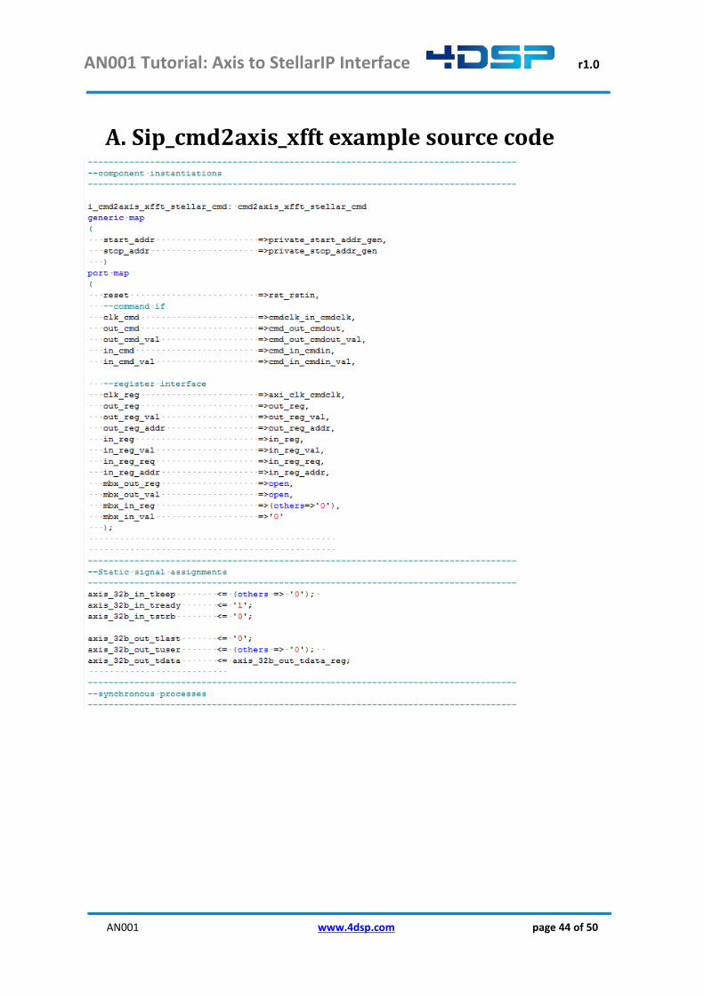
A. Sip_cmd2axis_xfft example source code

AN001 Tutorial: Axis to StellarIP Interface r1.0
AN001 www.4dsp.com page 45 of 50
AN001 Tutorial: Axis to StellarIP Interface r1.0
AN001 www.4dsp.com page 46 of 50
B. Sip_axis_32b_real2complex example source
code
AN001 Tutorial: Axis to StellarIP Interface r1.0
AN001 www.4dsp.com page 47 of 50
AN001 Tutorial: Axis to StellarIP Interface r1.0
AN001 www.4dsp.com page 48 of 50
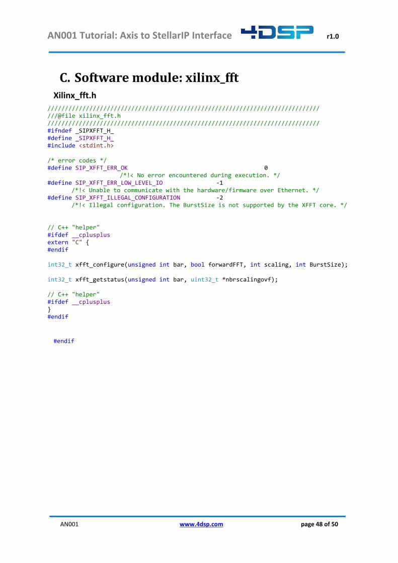
C. Software module: xilinx_fft Xilinx_fft.h
////////////////////////////////////////////////////////////////////////////// ///@file xilinx_fft.h ////////////////////////////////////////////////////////////////////////////// #ifndef _SIPXFFT_H_ #define _SIPXFFT_H_ #include <stdint.h> /* error codes */ #define SIP_XFFT_ERR_OK 0 /*!< No error encountered during execution. */ #define SIP_XFFT_ERR_LOW_LEVEL_IO -1 /*!< Unable to communicate with the hardware/firmware over Ethernet. */ #define SIP_XFFT_ILLEGAL_CONFIGURATION -2 /*!< Illegal configuration. The BurstSize is not supported by the XFFT core. */ // C++ "helper" #ifdef __cplusplus extern "C" { #endif int32_t xfft_configure(unsigned int bar, bool forwardFFT, int scaling, int BurstSize); int32_t xfft_getstatus(unsigned int bar, uint32_t *nbrscalingovf); // C++ "helper" #ifdef __cplusplus } #endif
#endif
AN001 Tutorial: Axis to StellarIP Interface r1.0
AN001 www.4dsp.com page 49 of 50
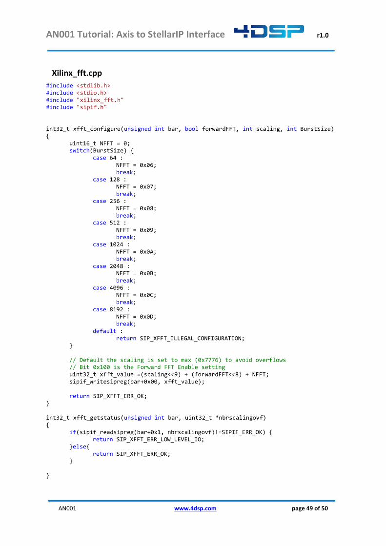
Xilinx_fft.cpp
#include <stdlib.h> #include <stdio.h> #include "xilinx_fft.h" #include "sipif.h" int32_t xfft_configure(unsigned int bar, bool forwardFFT, int scaling, int BurstSize) { uint16_t NFFT = 0; switch(BurstSize) { case 64 : NFFT = 0x06; break; case 128 : NFFT = 0x07; break; case 256 : NFFT = 0x08; break; case 512 : NFFT = 0x09; break; case 1024 : NFFT = 0x0A; break; case 2048 : NFFT = 0x0B; break; case 4096 : NFFT = 0x0C; break; case 8192 : NFFT = 0x0D; break; default : return SIP_XFFT_ILLEGAL_CONFIGURATION; } // Default the scaling is set to max (0x7776) to avoid overflows // Bit 0x100 is the Forward FFT Enable setting uint32_t xfft_value =(scaling<<9) + (forwardFFT<<8) + NFFT; sipif_writesipreg(bar+0x00, xfft_value); return SIP_XFFT_ERR_OK; } int32_t xfft_getstatus(unsigned int bar, uint32_t *nbrscalingovf) { if(sipif_readsipreg(bar+0x1, nbrscalingovf)!=SIPIF_ERR_OK) { return SIP_XFFT_ERR_LOW_LEVEL_IO; }else{ return SIP_XFFT_ERR_OK; } }
AN001 Tutorial: Axis to StellarIP Interface r1.0
AN001 www.4dsp.com page 50 of 50
D. Example constellation
out_data
out_data
cmd_clk
master_cmd_out
rst
clkrst
rst
rst
rst
rst
cmd_clkcmd_clk
cmd_clk
cmd_clkcmd_clk
cmd_clk
master_cmd_out
master_cmd_out
master_cmd_outmaster_cmd_out
master_cmd_out
clk
clk
clk
clk
tiedto0
cmd_clk
rst
cmd_clk
rst
cmd_clk
rst
master_cmd_out
xfft_cmd_out
xfft_cmd_out
fmc104_cmd_out
fmc104_cmd_out
s5d1_cmd_out
s5d1_cmd_out
rst
master_cmd_out
cmd_clk
cmdclk_in
cmd_in
rst
cmd_out
sip_cid
cmdclk_out
cmd_out
cmd_in
clkout
rst_out
in_data
out_data
sip_mac_engine
cmdclk_in
cmd_in
cmd_out
clk
rst
out0
in0
in1
in2
in3
in4
sip_router_s5d1
cmdclk_in
cmd_in
cmd_out
clk
rst
out0
in0
sip_fifo64k
clk
rst
cmdclk_in
cmd_in
cmd_out
adc0
adc1
adc2
adc3
sip_fmc104
clk
rst
cmdclk_in
cmd_in
cmd_out
sip_i2c_master
cmdclk_in
cmd0_in
cmd1_in
cmd2_in
cmd3_in
cmd4_in
cmd5_in
cmd6_in
cmd7_in
cmd8_in
cmd9_in
cmd10_in
cmd11_in
cmd_out
sip_cmd12_mux
cmdclk_in
cmd_in
rst
cmd_out
sip_fmc_ct_gen
clk
rst
cmd_in
axis_32b_in
axis_32b_out
cmd_out
sip_cmd2axis_xfft
clk
rst
data_in data_out
sip_axis_32b_in2wh_out
clk
rst
data_in data_out
sip_wh_in2axis_32b_out
data_out
clk
rst
data_in
sip_axis_32b_real2complex
clk
rst
data_in
control
data_out
status
sip_xfft_wrapper
cid_cmd_out
cid_cmd_out
i2c_cmd_out
i2c_cmd_out
adc0d
adc1d
adc2d
adc3d
adc0d
adc1d
adc2d
adc3ds5d1_d_out
s5d1_d_out
fifo_d_out
fifo_d_out
real_din real_din real_dout
real_dout
xfft_ctrl
xfft_ctrl
xfft_status
xfft_status
xfft_dout
xfft_dout
mac_din
mac_din
mac_cmdimac_cmdi
cmd_clk
rst
cmd_clk
rst
Title
Author
File
Revision
Constellation
Date Sheets
kc705_fmc104_xfft
iklink
4DSP
419_kc705_fmc104_xfft.dsn
1.0
419
Jan. 09, 2014 1 of 1


![2019 [Mustafa ARI]tez.sdu.edu.tr/Tezler/TF04245.pdfSİB Sinyal İşleme Birimi SPI Serial Peripheral Interface (Seri Çevresel Arabirim) ix SPP Streaming Parallel Port (Duraksız Paralel](https://img.pdfslide.tips/doc/110x75/61249671e6f0b609f4067fbf/2019-mustafa-aritezsduedutrtezler-sb-sinyal-leme-birimi-spi-serial.jpg)