Embed Size (px)
Citation preview
UNIVERSITI PUTRA MALAYSIA
DEVELOPMENT OF CARBON FIBER-REINFORCED CARBON COMPOSITE FORMULATIONS FOR BRAKE PAD
SARINA BINTI SULAIMAN
FK 2007 86
DEVELOPMENT OF CARBON FIBER-REINFORCED CARBON
COMPOSITE FORMULATIONS FOR BRAKE PAD
By
SARINA BINTI SULAIMAN
Thesis Submitted to the School of Graduate Studies, Universiti Putra Malaysia in Fulfilment of the Requirement for the degree of Master of Science
September 2007

DEDICATED TO
HUBBY, MY LOVING FAMILY, with love
ii
Abstrak tesis yang dikemukakan kepada Senat Universiti Putra Malaysia sebagai memenuhi keperluan untuk ijazah Master Sains
PENGHASILAN KOMPOSIT GENTIAN KARBON YANG DIPERKUATKAN
DENGAN KARBON UNTUK PENGGUNAAN PAD BREK
Oleh
SARINA BINTI SULAIMAN
September 2007
Pengerusi : Profesor Madya Robiah Yunus, PhD
Fakulti : Kejuruteraan
Sebelum ini, asbestos dan logam telah digunakan dalam pembuatan pad brek. Namun
pengunaan asbestos telah diharamkan kerana boleh menyebabkan kanser. Malah,
penggunaan logam juga telah dihadkan kerana habuk dari pad brek semasa pembrekan
boleh menyebabkan pencemaran air. Sejak itu, banyak kerja penyelidikan telah
dilakukan untuk menghasilkan pad brek tanpa penggunaan asbestos. Dalam kajian ini,
formula gentian karbon yang diperkuatkan dengan karbon untuk penggunaan pad brek
telah dihasilkan dan kekuatan mekanikal komposit ini telah dikaji. Komposit ini
dihasilkan kerana mempunyai kekuatan yang tinggi, ringan dan berkeupayaan untuk
mengekalkan sifat mekanikalnya pada suhu lebih daripada 2000 oC dalam atmosfera
yang tidak mempunyai oksida. Kaedah yang digunakan dalam penghasilan komposit
karbon-karbon untuk penggunaan dalam brek automotif adalah dengan gentian karbon
dan phenolic resin ditekan panas oleh alat penempaan tekanan panas. Kemudiannya,
komposit berkenaan dikarbonkan pada suhu 1000oC dan akhirnya dibakar pada suhu
1700oC. Empat langkah rendaman dilakukan semasa proses pengkarbonan pada suhu
v
vi
1000oC. Dalam kajian ini, kesan penambahan gentian karbon dan pengeras dan kesan
pengkarbonan dan penggrafitan pada sifat komposit karbon dan pad brek komersil telah
dikaji dengan menggunakan ujian mekanikal, haba dan geseran. Komposit dengan
pengunaan 40 peratus gentian karbon dan 15 peratus pengeras menunujukkan sifat
mekanikal dan terma yang bagus selepas diawet. Kekuatan ketegangan dan lenturan bagi
komposit yang telah diawet adalah masing-masing, 411.9 MPa dan 51.7 MPa sebelum
diturunkan pada suhu 523oC. Kekuatan lenturan dan ketegangan bagi komposit yang
telah melalui proses pengrafitan pada suhu 1700oC adalah masing-masing, 10.7 MPa dan
10.8 MPa. Ketumpatan komposit yang telah diawet adalah 1.21 g/cm3 dan meningkat
kepada 1.45 g/cm3 setelah digrafitkan pada 1700oC. Kekuatan lentur dan ketumpatan
meningkat dengan proses rendaman semasa proses pengkarbonan. Analisis terma
menunjukkan pad brek dalam pasaran diturunkan pada suhu 700oC, iaitu jauh lebih
rendah daripada komposit karbon. Komposit karbon yang telah melalui proses
pengrafitan tidak diturunkan walaupun pada suhu 800oC. Komposit karbon telah
menunjukkan sifat mekanikal, haba dan geseran yang baik jika dibandingkan dengan
pad brek komersil.

ACKNOWLEDGEMENTS
First and foremost, I would like to extend my deepest praise to Allah S.W.T who has
given me the patience, strength, determination and courage to complete this thesis.
I would like to take this opportunity to express my sincere gratitude to my main
supervisor, Assoc. Prof. Dr. Robiah Yunus for her guidance, suggestions and
willingness to assist me through the whole course of this research project. I also
would like to acknowledge my supervisory committee, Dr NorAzowa and Dr
El-Sadiq for constantly guiding and encouraging me throughout my study. Without
my supervisor and committee’s valuable advice and support, it would not be possible
for me to complete my research.
I would also like to deeply appreciate numerous individual who gave technical
support and sincere assistance throughout my experiment and special thanks to Mr
Meor and Puan Suryani, for their assistance. My sincere appreciation also goes to my
friends and to people who helped me.
Last but not least, my greatest appreciation will always go to my husband and my
loving family for their sacrifices, love, patient and support.
vii

This thesis submitted to the Senate of Universiti Putra Malaysia and has been accepted as fulfillment of the requirement for the degree of Master of Science. The members of the Supervisory Committee are as follows: Robiah Yunus, PhD Associate Professor Faculty of Engineering Universiti Putra Malaysia (Chairman) NorAzowa, PhD Lecturer Faculty of Science Universiti Putra Malaysia (Member) El-Sadiq, PhD Lecturer Faculty of Engineering Universiti Putra Malaysia (Member)
______________________ AINI IDERIS, PhD Professor / Dean School of Graduate Studies Universiti Putra Malaysia
Date:
ix

DECLARATION
I hereby declare that the thesis is based on my original work except for quotations and citations, which have been duly acknowledged. I also declare that it has not been previously or concurrently submitted for any other degree at Universiti Putra Malaysia or other institutions.
__________________________ SARINA BINTI SULAIMAN
Date:
x
TABLE OF CONTENTS
Page
DEDICATION ii ABSTRACT iii ABSTRAK vi ACKNOWLEDGEMENTS vii APPROVAL viii DECLARATION x LIST OF TABLES xiii LIST OF FIGURES xiv LIST OF ABBREVIATIONS xvii CHAPTER 1 INTRODUCTION 1.1
1.1 Introduction 1.1 1.2 Objectives and Scopes of Work 1.5 1.3 Thesis Outline 1.5
2 LITERATURE REVIEW 2.1
2.1 Carbon fibers 2.1 2.2 Carbon Fiber Reinforced Composites 2.3
2.2.1 Carbon Fiber Reinforced Thermoplastic (CFRP) 2.5 2.2.2 Carbon Fiber Reinforced Metal 2.6 2.2.3 Carbon Fiber Reinforced Carbon 2.6
2.3 Formulation of Carbon-Carbon Composites 2.10 2.3.1 Chemical Vapor Infiltration (CVI) 2.10 2.3.2 Using Resin 2.11 2.3.3 Using Pitch 2.12
2.4 Brake Pad 2.12 2.4.1 Types of brake pad 2.16
2.5 Matrixes 2.26 2.5.1 Polymers 2.27 2.5.2 Phenolic Resin 2.30
3 METHODOLOGY 3.1 3.1 Materials 3.1 3.2 Preparation of specimens 3.1 3.3 Molding the specimens 3.4 3.4 Curing Process 3.6 3.5 Carbonization 3.6
xi
xii
3.6 Graphitization 3.7 3.7 Mechanical testing 3.9
3.7.1 Tension Test 3.9 3.7.2 Flexural Test 3.10 3.7.3 Hardness-Rockwell l Test 3.12 3.7.4 Density 3.12
3.8 Thermal analysis 3.12 3.8.1 Dynamic Mechanical Analysis (DMA) 3.13 3.8.2 Thermogravimetric Analysis (TGA) 3.13
3.9 Scanning Electron Microscopy (SEM) 3.14 3.10 Tribological 3.14
3.10.1 Friction and Wear Test 3.14
4 RESULTS AND DISCUSSION 4.1 4.1 Introduction 4.1 4.2 Effect of Hardener and Fiber Loading 4.2
4.2.1 Tension Test Analysis 4.2 4.2.2 Flexural Test Analysis 4.7 4.2.3 Hardness Test Analysis 4.11 4.2.4 Density Analysis 4.14 4.2.5 Dynamic Mechanical Analysis (DMA) 4.16 4.2.6 Thermogravimetric Analysis (TGA) 4.21
4.3 Effect of Carbonization and Graphitization 4.24 4.3.1 Tension Test Analysis 4.24 4.3.2 Flexural Test Analysis 4.27 4.3.3 Hardness Analysis 4.30 4.3.4 Density Analysis 4.31 4.3.5 Dynamic Mechanical Analysis (DMA) 4.32 4.3.6 Thermogravimetric Analysis (TGA) 4.33
4.4 Scanning Electron Microscopy (SEM) 4.36 4.5 Friction and Wear Test Analysis 4.40 4.6 Comparison between Commercialized brake pad and CC brake
Pad 4.42
5 CONCLUSION AND RECOMMENDATIONS 5.1 5.1 Conclusions 5.1 5.2 Recommendations for Future Work 5.5
REFERENCES R.1 APPENDICES A.1 B.1 BIODATA OF AUTHOR C.1
LIST OF ABBREVIATIONS
Tg Glass transition temperature
CF Carbon fiber
Hr Hardener
CC Carbon Carbon Composites
HRR Hardness unit
σ Strength
SEM Scanning electron microscopy
TGA Thermogravimetric analysis
DMA Dynamic mechanical analysis
CVI Chemical vapour infiltration
RDD Rapid direction diffused
Vol Volume
E Modulus of elasticity, MPa
d Depth of beam tested for flexural test, mm
m Slope of the tangent to the initial straight line portion of the load-deflection curve for flexural test, N/mm of deflection
b Width of beam tested for flexural test, mm
L Support span for flexural test, mm
R Rate of crosshead motion for flexural test, mm/min
Z Rate of straining of the outer fiber for flexural test, mm/mm/min. Z shall be equal to 0.01
xvii
P Load for flexural test, N
HS High strength
IM Intermediate modulus
HM High modulus
UHM ultra high modulus
PAN Polyacrylonitrile
CFRP Carbon fiber reinforced thermoplastic
xviii
LIST OF FIGURES
Figure Page
2.1 Schematic drawing of PAN and Pitch processes 2.3
2.2 Brake pads 2.13
2.3 Sections of a pad 2.15
2.4 Schematic of a disc brake and brake pads 2.16
2.5 Schematic of the furnace for RDD method 2.21
2.6 Model for decomposed products of phenolic resin-based on C/C composites during pyrolysis
2.23
2.7 Inertial brake dynamometer used for friction and wear testing 2.25
2.8 Schematic diagram of (a) thermoplastic (b) thermosetting polymers 2.28
2.9 Structure of phenolic resin 2.31
2.10 Three dimensional model of a polymerized phenolic resin 2.31
3.1 Carbon fibers 3.2
3.2 Fibers arrangement in 0/90odirection 3.2
3.3 Hot press 3.5
3.4 Hot press mold: 15cm x 15cm x 0.1cm 3.5
3.5 1200oC Furnace-carbonization 3.7
3.6 Furnace 1700oC-graphitization 3.8
3.7 Flow diagram of CC composites preparation by impregnation 3.8
3.8 Tensile test specimen-dog bone 3.9
3.9 Flexural test specimen 3.10
3.10 Three-point flexural test 3.10
xiv
4.1 Effect of fiber loading on tensile strength 4.3
4.2 Effect of hardener on tensile strength 4.4
4.3 Effect of fiber loading on tensile modulus
4.5
4.4 Effect of hardener on tensile modulus 4.6
4.5 Effect of fiber loading on flexural strength 4.8
4.6 Effect of hardener on flexural strength 4.9
4.7 Effect of fiber loading on flexural modulus 4.9
4.8 Effect of hardener on flexural modulus 4.11
4.9 Hardness at different percentages of hardener and fiber loading 4.12
4.10 Effect of percentages of hardener and fiber loading on the density of cured composites
4.15
4.11 Effect of percentages of hardener and fiber loading on the density of the composites before and after curing
4.15
4.12 Tan delta of different percentages of hardener at 40% volume fraction of fibers
4.18
4.13 Tan delta of the composites at different volume fraction of fiber at 15% hardener
4.20
4.14 Tan delta of the composites at different volume fraction of fiber at 5% hardener
4.20
4.15 Typical TGA thermogram 4.22
4.16 Tensile strength of composites at different densification 4.25
4.17 Tensile modulus of composites at different stages 4.25
4.18 Flexural strength of composites at different stages
4.28
xv
4.19 Flexural modulus of composites at different stages 4.29
4.20 Hardness of the composites at different stages 4.30
4.21 DMA results: Tan delta of different densification of composites 4.33
4.22 TGA graph of second densified composites 4.35
4.23 SEM micrograph of fractured surface cured samples with 15% hardener and 40% CF
4.36
4.24 SEM micrograph of fractured surface of carbonized (2 dense) composites
4.38
4.25 SEM micrograph of fractured surface of carbonized (4 dense) composites
4.39
4.26 SEM micrograph of fractured surface of graphitized composites (CC)
4.39
xvi
LIST OF TABLES
Table Page
1.1 The long fiber reinforced thermoplastics market 1.2
2.1 Composites and their important features 2.5
2.2 Properties of Carbon-Carbon Composites 2.9
2.3 The characteristic of the Asbestos 2.17
2.4 Summary of material present in brake pad 2.19
2.5 Typical ranges of the common constituents in industry 2.19
2.6 Carbon fibers content 2.20
2.7 Matrix Materials 2.29
3.1 Composition of carbon fibers and phenolic resin (1mm thickness) 3.3
3.2 Compositions of hexamine by volume percentage of Phenolic resin 3.4
4.1 Effect of hardener at 40% fiber loading of the composites 4.18
4.2 Effect of fiber loading on the Tg and Tan Delta of the composites 4.19
4.3 Thermal Decomposition of the composites 4.23
4.4 Density at different densification of the composites 4.31
4.5 Glass transition temperature for different type of composites
4.32
4.6 Thermal decomposition and char yield of the composites 4.34
4.7 Average Coefficient of Friction of the Composites 4.40
4.8 Comparison between mechanical, thermal and tribological properties of graphitized and commercialized brake pads
4.44
xiii
CHAPTER 1
INTRODUCTION
1.1 Introduction
Carbon fiber was introduced as a filament material for the lamp in 1890 by Thomas Alva
Edison. It was stated that this carbon fiber had poor mechanical strength. Therefore,
around 1950s, The National Carbon Company in USA introduced a carbon cloth made
by carbonizing rayon cloth. In 1964, Thornel 25 was introduced in the market with
ultimate tensile strength (UTS) of 1.25 GPa and Young Modulus’s of 170 GPa at a price
of more than £1000 per kg (Morgan, 2005).
The unique features of carbon fiber are low density, high strengths, lightweight, high
modulus and high stiffness leading to the development of new industrial applications.
Commonly, carbon fiber is used in the following three sectors: (1) High technology
areas including aerospace and nuclear engineering; (2) General engineering and
transportation sector, including engineering components such as bearing, gears, cams,
fan blades and automobile bodies; (3) Sporting goods, such as golf clubs and bicycles
(Donnet et al., 1998).
The cost to purchase commercial-grade carbon fibers is between $8 and $10 per pound,
and at the moment, the manufacturers are trying to reduce the price to between $3 and
$5 per pound. At that price, annually automakers can use approximately 300 pounds of
composites per vehicle in the manufacturing of cars. According to some studies,
replacing half of the ferrous metals in current automobiles could reduce a vehicle’s
weight by 60 percent and fuel consumption by 30 percent (www.azom.com).
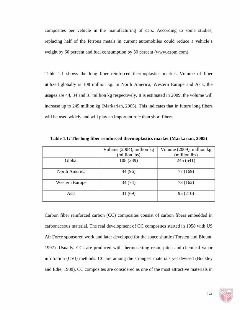
Table 1.1 shows the long fiber reinforced thermoplastics market. Volume of fiber
utilized globally is 108 million kg. In North America, Western Europe and Asia, the
usages are 44, 34 and 31 million kg respectively. It is estimated in 2009, the volume will
increase up to 245 million kg (Markarian, 2005). This indicates that in future long fibers
will be used widely and will play an important role than short fibers.
Table 1.1: The long fiber reinforced thermoplastics market (Markarian, 2005)
Volume (2004), million kg (million lbs)
Volume (2009), million kg (million lbs)
Global 108 (239) 245 (541)
North America 44 (96) 77 (169)
Western Europe 34 (74) 73 (162)
Asia 31 (69) 95 (210)
Carbon fiber reinforced carbon (CC) composites consist of carbon fibers embedded in
carbonaceous material. The real development of CC composites started in 1958 with US
Air Force sponsored work and later developed for the space shuttle (Torsten and Blount,
1997). Usually, CCs are produced with thermosetting resin, pitch and chemical vapor
infiltration (CVI) methods. CC are among the strongest materials yet devised (Buckley
and Edie, 1988). CC composites are considered as one of the most attractive materials in
1.2
the space shuttle applications and used as components that can withstand high
temperature (Manocha, 2003).
CC composites are introduced as automotive brake pad to substitute asbestos based
brake pad. Since asbestos are banned because of its carcinogenic, a lot of researches are
done to produce asbestos free brake pads. Thus, brake pads have experienced major
changes in their formulations during the last two decades due to health issues related to
asbestos fibers. There has been a significant effort to develop high performance non-
asbestos linings (Cho et al., 2001).
Brake pad can be categorized into four major types: metallic, semi-metallic, non-
asbestos organic and CC composites. In the late 1970s, teams Brabham (Formula 1
team) were interested in CC brake pad and entered into agreement with HITCO Carbon
Composites to develop CC brake pad for F1 racing circuit (Morgan, 2005 and Ho et al.,
2005). Semi-metallic friction material was introduced in the late 1960s and has gained
widespread usage in the mid-1970s. It has been exploited for parts such as clutches and
brake pads used in automotive transmission in both dry and wet circumstances.
Phenolic resins are the oldest synthetic polymers used commercially, around the
beginning of the 20th century. These thermoset resins have typically been cured at high
temperatures (140-180oC) and usually high pressures. Commonly, phenolic resins are
used in a broad range of applications such as paints, adhesives and composites. There
are two types of phenolic resins, the resole type and the novolac type, depending on the
method of synthesis and the catalysts used. Phenolic resin provides intermolecular
1.3
hydrogen bonding as a dominant driving force to interact with hydroxyl, carbonyl,
amide, ester, and other hydrogen-bonding functional groups (Chen Chi et al., 2001).
Phenolic resins exhibits low-molecular-weight; fusible and soluble resin that may be
easily handled and polymerized to a high-molecular-weight, strong, heat resistant cross-
linked structures. That is the basis for the varied and important uses to which phenolic
resins are put throughout the world (Encyclopedia of Polymer Science and
Technology, 1964). Phenolic resin became brittle once cured and has low impact
resistance. However this liquid is used widely as a binder for brake pad. It also been
mentioned that phenolic resin carbonized at approximately 450oC and will decrease the
density of brake friction at the wear surface and increases the porosity. This process will
change the structural and frictional characterization of the friction material (Chan and
Stachowiak, 2004).
In this study, the main components of brake pad are carbon fibers and phenolic resin.
Even though the raw material, carbon fibers are expensive but at the moment, the costs
of replacement parts and service are expensive. Alternatively, high-performance
materials i.e., CC composites are available at a slightly higher initial cost. In addition to
replacement costs, consumer complaints of excessive noise and pad residue
accumulating on the wheels have left manufacturers dissatisfied with the current semi
metallic brake pads (Chapman et al., 1999).
1.4
1.2 Objectives and Scopes of Work
The objectives of this project are:
i. to develop and investigate the optimum formulation for carbon-carbon
composites for brake pad application.
ii. to analyze the properties of cure, carbonized and graphitized composites.
In order to achieve the project’s objective, the following studies are carried out i.e., the
effects of volume fraction of carbon fiber, effects of percentages of hardener, effects of
carbonization cycles and effects of graphitization on mechanical, thermal and
tribological properties. Formulated composites are tested after each process: post curing,
carbonization and graphitization. The mechanical testing that are used to analyze the
formulated CC are tensile, flexural, dynamic mechanical analysis, hardness and density
test. The thermal properties, DMA and TGA, and tribological property, friction are
investigated. Finally, the properties of graphitized composites are compared with the
commercialized brake pad.
1.3 Thesis Outline
This thesis consists of five chapters. Chapter one contains introduction and background
of the thesis, objectives and finally the scopes of work. Chapter two consists of literature
review of carbon fiber, composites, polymers, CC composites and brake pad, and
previous works done that are related to the thesis. Chapter three presents research
methodology and describes the equipment used in this project. Chapter four consists of
1.5
1.6
results obtained from the experiment and comparison between the commercialized brake
pad and graphitized composites. The chapter also includes the discussion of the results
of each step: post curing, carbonization and graphitization. Finally, Chapter five
summarizes and concludes the work that has been carried out. Lastly the future work is
suggested at the end of chapter.
CHAPTER 2
LITERATURE REVIEW
2.1 Carbon Fibers
Carbon fibers are gradually becoming the most advanced product after the introduction
of composite-bodied Corvette. In 1953, the unique features of carbon fibers were
lightweight, low density, high strength, high modulus and high stiffness which led to the
development of new industrial applications. Carbon fibers processes include controlled
oxidation, carbonization and graphitization of carbon-rich organic precursors. Carbon
fibers are usually grouped according to the modulus band: high strength (HS),
intermediate modulus (IM), high modulus (HM) and ultra high modulus (UHM)
(Buckley and Edie, 1988). On the whole, in 1993 United States consumption of carbon
fibers was 2.8 million kg (Donnet et al., 1998).
Structurally, carbon fibers contain a blend of amorphous carbon and graphitic carbon.
Carbon fibers are commercially available in three forms: long and continuous tow,
chopped and milled. Graphitic form of carbon fibers in which carbon atoms are arranged
in crystallographically parallel planes of regular hexagon, results in high modulus
carbon fibers. The advantages of carbon fibers are high tensile strength, high modulus,
low coefficient of thermal expansion, lightweight and high fatigue strength (Mallick,
1993).
The mechanical properties of composites are related to the length of the reinforcing
fibers. In composites, carbon fibers are usually used in the form of short, long and long
and continuous. Usually an average fiber length of approximately 5-20 mm is
considered a long fiber and less than 1 mm is considered short fiber (Frank et al., 2005).
Common methods of processing carbon fibers are by using polyacrylonitrile (PAN) and
pitch. PAN is a synthetic fiber that is pre-manufactured and wound into spools, while
pitch is a coal-tar petroleum product that is melted, stretched and made into fibers. In the
carbon fibers manufacturing process, these fibers are first stretched and heated (up to
400°C) in the thermoset polymer treatment. This first step results in the oxidation of the
organic material. The material is then carbonized by being heated to approximately
800°C in vacuum and the non-carbon impurities are removed. After the material is
carbonized, it is graphitized by stretching the fibers between 50-100% and heating them
up to temperatures between 1100°C and 3000°C. Processes to produce carbon fiber can
be seen in Figure 2.1 (Sung et al., 2001).
2.2
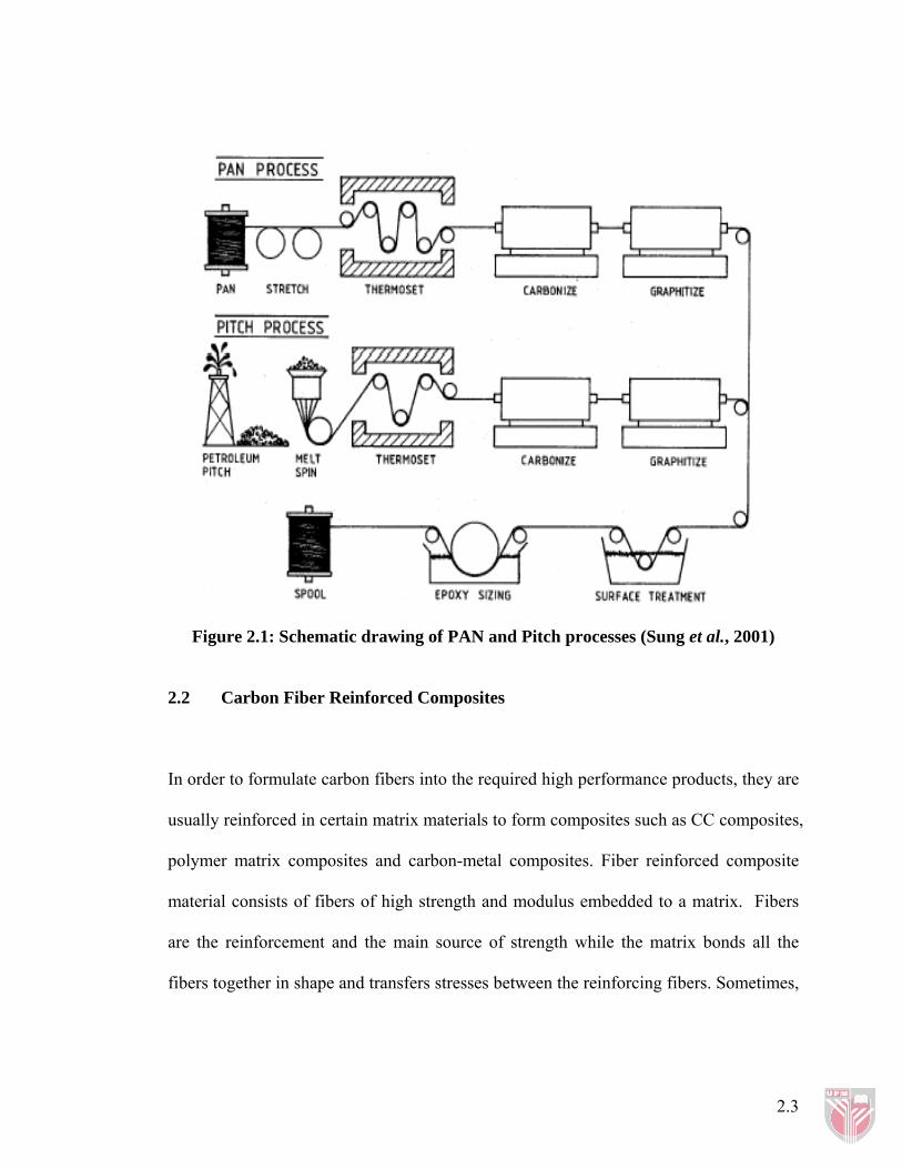
Figure 2.1: Schematic drawing of PAN and Pitch processes (Sung et al., 2001)
2.2 Carbon Fiber Reinforced Composites
In order to formulate carbon fibers into the required high performance products, they are
usually reinforced in certain matrix materials to form composites such as CC composites,
polymer matrix composites and carbon-metal composites. Fiber reinforced composite
material consists of fibers of high strength and modulus embedded to a matrix. Fibers
are the reinforcement and the main source of strength while the matrix bonds all the
fibers together in shape and transfers stresses between the reinforcing fibers. Sometimes,
2.3