Embed Size (px)
Citation preview
8/11/2019 Vesigial Signals
http://slidepdf.com/reader/full/vesigial-signals 1/16
1
Vestigial Sideband (VSB)
Modulation
8/11/2019 Vesigial Signals
http://slidepdf.com/reader/full/vesigial-signals 2/16
2
VSB Modulation
Basic idea
Signal generation
VSB Demodulation
Heterodyning
Vestigial Sideband (VSB) Modulation
8/11/2019 Vesigial Signals
http://slidepdf.com/reader/full/vesigial-signals 3/16
3
Vestigial Sideband Transmission
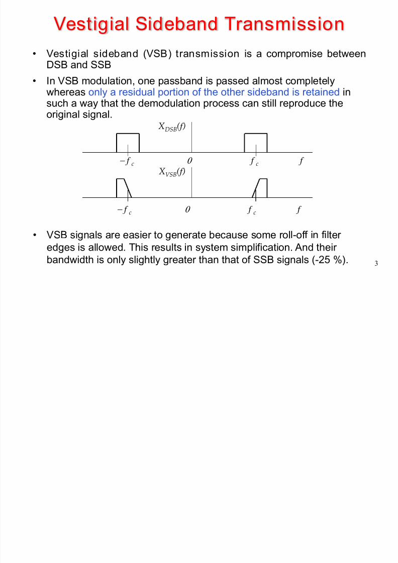
• Vestigial sideband (VSB) transmission is a compromise betweenDSB and SSB
• In VSB modulation, one passband is passed almost completelywhereas only a residual portion of the other sideband is retained insuch a way that the demodulation process can still reproduce theoriginal signal.
f c− f c 0 f
XDSB( f )
f c− f c 0 f
XVSB( f )
• VSB signals are easier to generate because some roll-off in filter
edges is allowed. This results in system simplification. And theirbandwidth is only slightly greater than that of SSB signals (-25 %).
8/11/2019 Vesigial Signals
http://slidepdf.com/reader/full/vesigial-signals 4/16
4
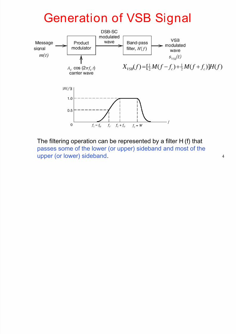
Generation of VSB Signal
The filtering operation can be represented by a filter H (f ) that
passes some of the lower (or upper) sideband and most of the
upper (or lower) sideband.
)()]()([)(21
21 f H f f M f f M f X ccVSB ++−=
m(t)
8/11/2019 Vesigial Signals
http://slidepdf.com/reader/full/vesigial-signals 5/16
8/11/2019 Vesigial Signals
http://slidepdf.com/reader/full/vesigial-signals 6/16
6
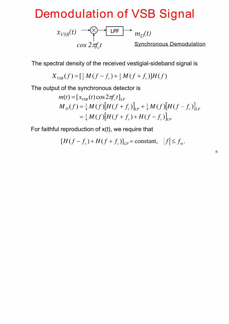
Demodulation of VSB Signal
The spectral density of the received vestigial-sideband signal is
)()]()([)(21
21 f H f f M f f M f X ccVSB ++−=
The output of the synchronous detector is
LPcVSB t f t xt m ]2cos)([)( π =
[ ] [ ]
[ ] LPcc
LPc LPc D
f f H f f H f M
f f H f M f f H f M f M
)()()(
)()()()()(
41
41
41
−++=
−++=
For faithful reproduction of x(t), we require that
. constant,)]()([ m LPcc f f f f H f f H ≤=++−
LPF mD(t)
cos 2π f ct
xVSB(t)
Synchronous Demodulation
8/11/2019 Vesigial Signals
http://slidepdf.com/reader/full/vesigial-signals 7/16
7
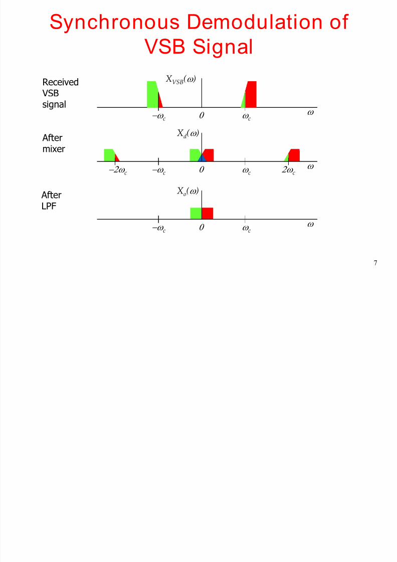
Synchronous Demodulation of
VSB Signal
ω c−ω c 0 ω
XVSB(ω )
ω c−ω c 0 ω
Xd(ω )
−2ω c 2ω c
ω c−ω c 0 ω
Xo
(ω )
AfterLPF
After
mixer
Received VSBsignal
8/11/2019 Vesigial Signals
http://slidepdf.com/reader/full/vesigial-signals 8/16
8
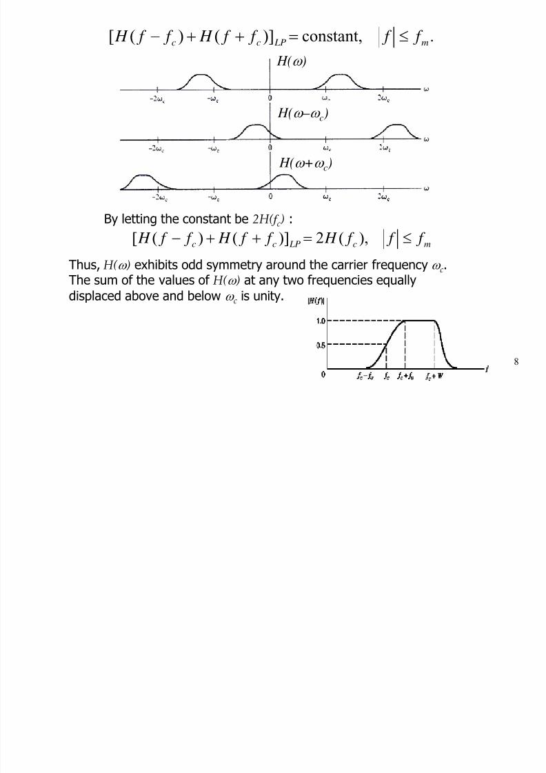
. constant,)]()([ m LPcc f f f f H f f H ≤=++−
By letting the constant be 2H( f c) :
mc LPcc f f f H f f H f f H ≤=++− ),(2)]()([
Thus, H(ω ) exhibits odd symmetry around the carrier frequency
ω c.The sum of the values of H(ω ) at any two frequencies equally
displaced above and below ω c is unity.
H(ω
)
H(ω – ω c)
H(ω +ω c)
8/11/2019 Vesigial Signals
http://slidepdf.com/reader/full/vesigial-signals 9/16
9
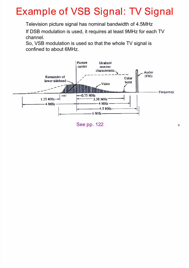
Television picture signal has nominal bandwidth of 4.5MHz
If DSB modulation is used, it requires at least 9MHz for each TV
channel.
So, VSB modulation is used so that the whole TV signal is
confined to about 6MHz.
Example of VSB Signal: TV Signal
See pp. 122
8/11/2019 Vesigial Signals
http://slidepdf.com/reader/full/vesigial-signals 10/16
10
VSB Modulation
Basic idea
Signal generation
VSB Demodulation
Heterodyning
Vestigial Sideband (VSB) Modulation
8/11/2019 Vesigial Signals
http://slidepdf.com/reader/full/vesigial-signals 11/16
11
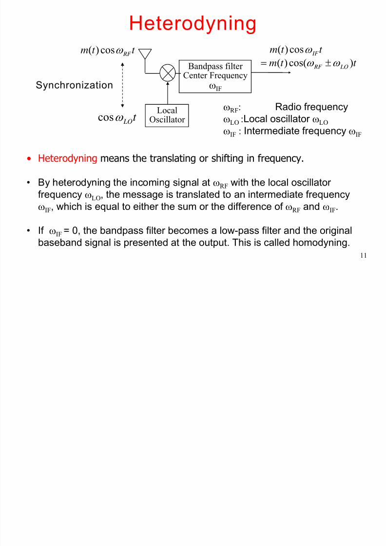
Heterodyning
t LOω cos
t t m RF ω cos)(
Synchronization
Bandpass filter Center Frequency
ωIF
t t m IF ω cos)(
LocalOscillator
ωRF: Radio frequency
ωLO :Local oscillator ωLO
ωIF : Intermediate frequency ωIF
• Heterodyning means the translating or shifting in frequency.
• By heterodyning the incoming signal at ωRF with the local oscillator
frequency ωLO, the message is translated to an intermediate frequencyωIF, which is equal to either the sum or the difference of ωRF and ωIF.
• If ωIF = 0, the bandpass filter becomes a low-pass filter and the original
baseband signal is presented at the output. This is called homodyning.
t t m LO RF )cos()( ω ω ±=
8/11/2019 Vesigial Signals
http://slidepdf.com/reader/full/vesigial-signals 12/16
12
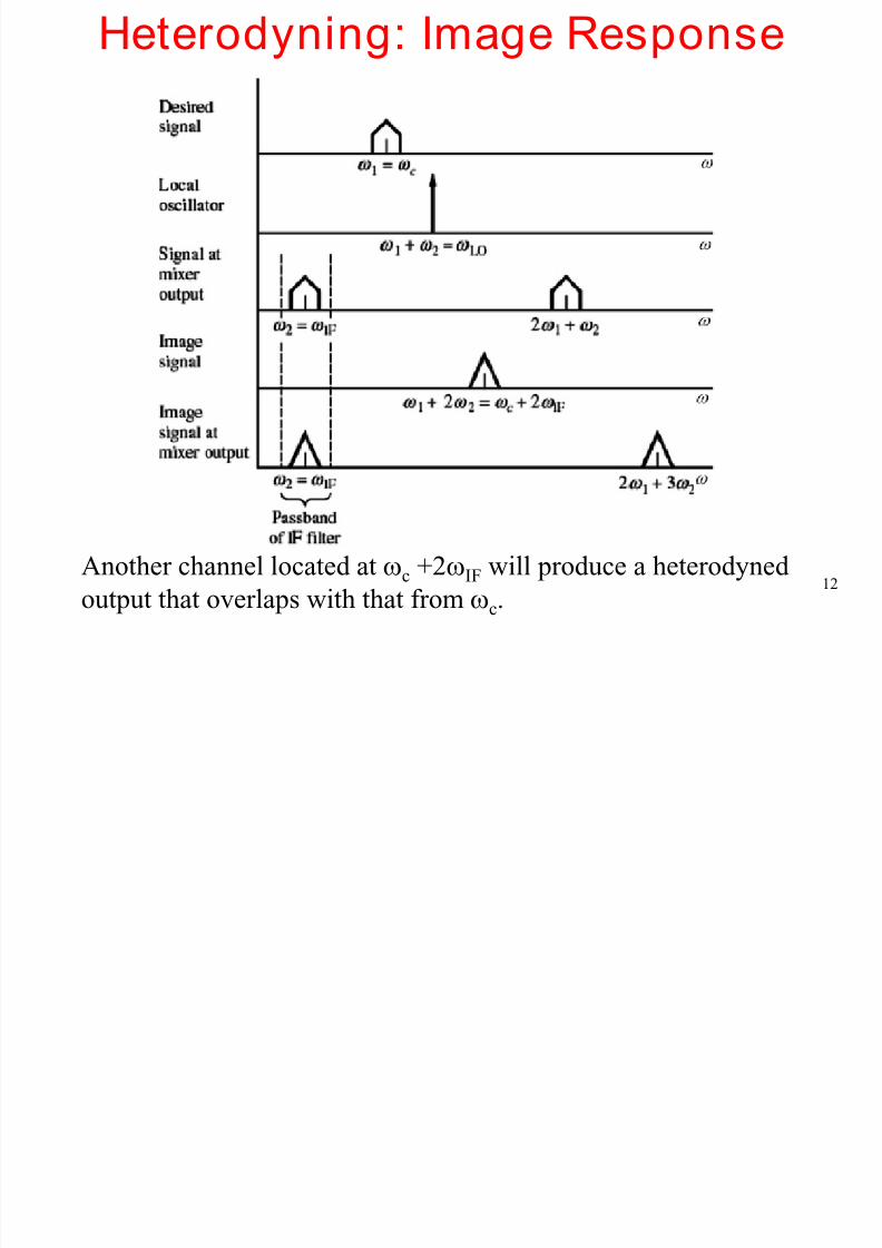
Heterodyning: Image Response
Another channel located at ωc +2ωIF will produce a heterodyned
output that overlaps with that from ωc.
8/11/2019 Vesigial Signals
http://slidepdf.com/reader/full/vesigial-signals 13/16
13
Heterodyning: Image Response
Methods to solve the image response in heterodyne
receiver
1. Careful selection of intermediate frequency ωIF for a
given frequency band.
2. Attenuate the image signal before heterodyning
8/11/2019 Vesigial Signals
http://slidepdf.com/reader/full/vesigial-signals 14/16
14
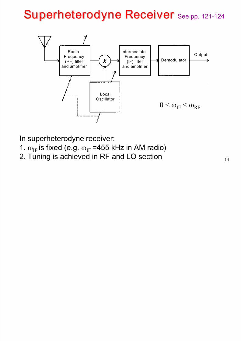
Superheterodyne Receiver See pp. 121-124
Radio-
Frequency
(RF) filter and amplifier
Intermediate--
Frequency
(IF) fil ter and ampli fier
Demodulator
Output
Local
Oscillator
In superheterodyne receiver:
1. ωIF is fixed (e.g. ωIF =455 kHz in AM radio)2. Tuning is achieved in RF and LO section
0 < ωIF < ωRF
8/11/2019 Vesigial Signals
http://slidepdf.com/reader/full/vesigial-signals 15/16
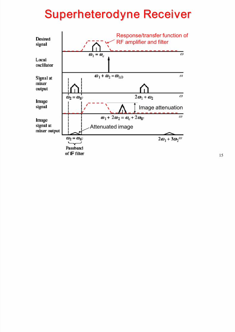
15
Superheterodyne Receiver
Attenuated image
Image attenuation
Response/transfer function of
RF amplifier and filter
8/11/2019 Vesigial Signals
http://slidepdf.com/reader/full/vesigial-signals 16/16
16
• We have introduced linear modulation. Inparticular,
• DSB-SC, Double sideband suppressed carrier
• DSB-LC, Double sideband large carrier (AM)• SSB, Single sideband
• VSB, Vestigial sideband
Summary