Embed Size (px)
Citation preview
Charles McClintonNASA Langley Research Center
(Retired)Hampton, VA
X-43: Scramjet Power Breaks the Hypersonic BarrierX-43: Scramjet Power Breaks the Hypersonic Barrier
X-43 SIGMA06012004|McClinton.ppt #1
Dryden Lecture44th AIAA Aerospace Sciences
Meeting and Exhibit9 Jan. 2006Reno, NE
22
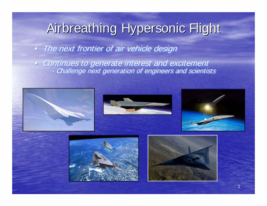
Airbreathing Hypersonic FlightAirbreathing Hypersonic FlightAirbreathing Hypersonic Flight• The next frontier of air vehicle design
• Continues to generate interest and excitement- Challenge next generation of engineers and scientists
• The next frontier of air vehicle design
• Continues to generate interest and excitement- Challenge next generation of engineers and scientists

IAC04-06 X43Flght|McClinton.ppt #3
IAC04-06 X43Flght|McClinton.ppt #4
Turbine
Scramjet
Ramjet
0 10 20MACH NUMBER
Isp
Rocket
Ramjet fuel injection
Inlet
Isolator
Ramjet Inlet Throat
Ramjet combustorMach ~ 0.2
~Air
Ramjet Second Min.(Nozzle Throat)
Nozzle
Module
Scramjet fuel injection
Inlet
Isolator
Scramjet Combustor
Scramjet internal nozzle
~
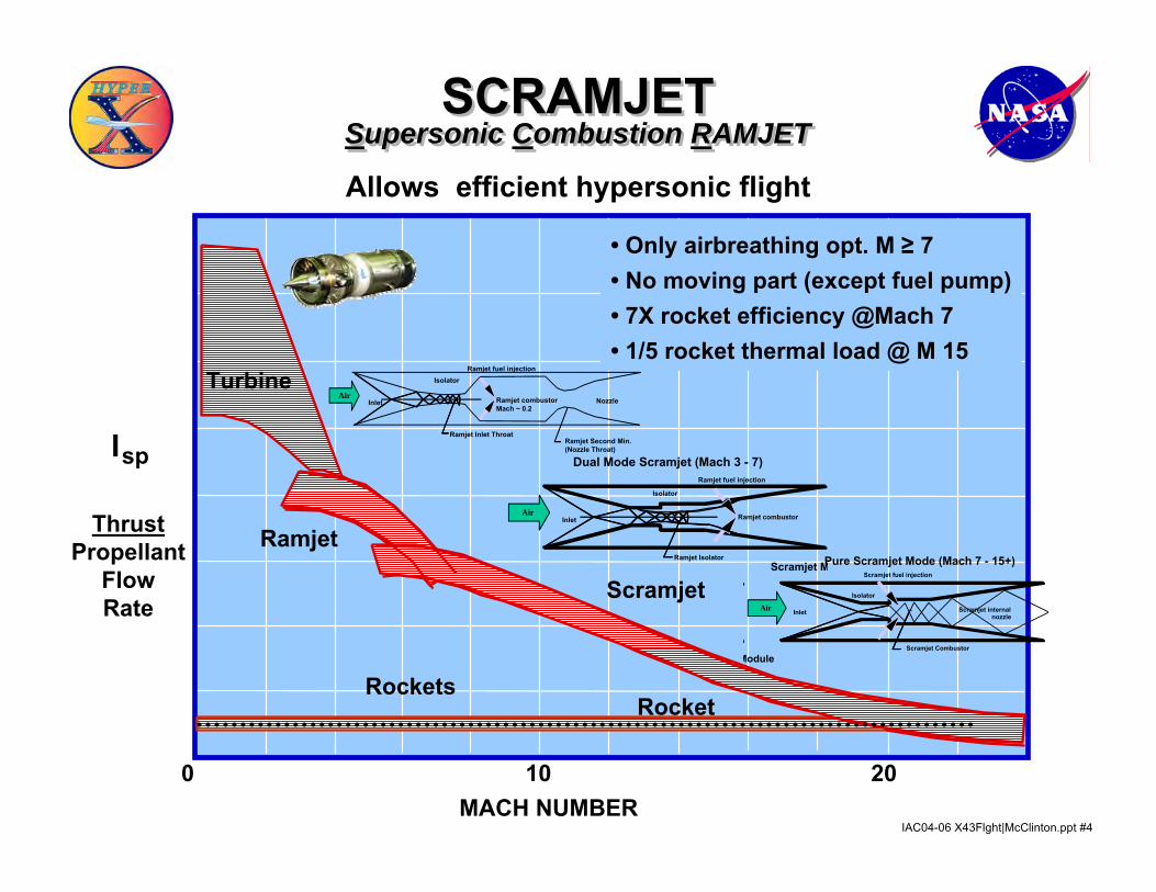
Pure Scramjet Mode (Mach 7 - 15+)
Air
Scramjet M
Ramjet fuel injection
Inlet
Isolator
Ramjet Isolator
Ramjet combustor~
Dual Mode Scramjet (Mach 3 - 7)
Air
Rockets
• Only airbreathing opt. M ≥ 7• No moving part (except fuel pump)• 7X rocket efficiency @Mach 7• 1/5 rocket thermal load @ M 15
Allows efficient hypersonic flight
ThrustPropellant
FlowRate
SCRAMJETSupersonic Combustion RAMJET
SCRAMJETSupersonic Combustion RAMJET

IAC04-06 X43Flght|McClinton.ppt #5IAC04-06 X43Flght|McClinton.ppt #10
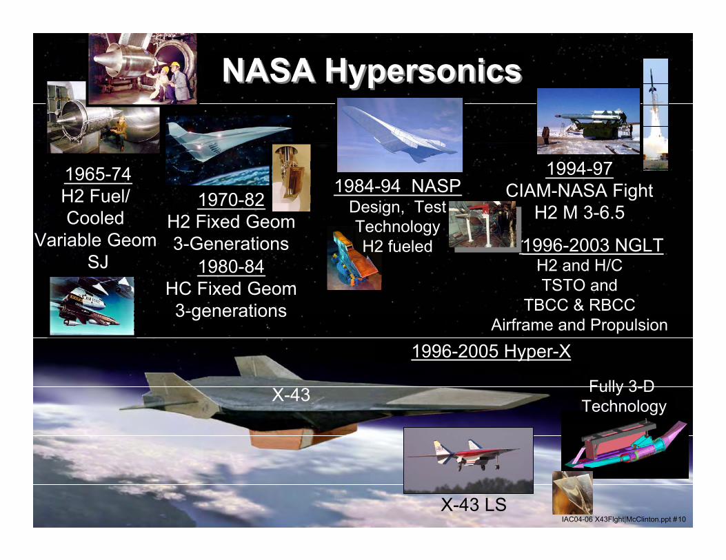
NASA HypersonicsNASA Hypersonics
1965-74H2 Fuel/ Cooled
Variable Geom SJ
1970-82H2 Fixed Geom3-Generations
1994-97CIAM-NASA Fight
H2 M 3-6.5
Fully 3-D Technology
1980-84HC Fixed Geom3-generations
1996-Today Hyper-X
X-43
X-43 LS
1995-2004 SLIH2 and H/CTSTO and
TBCC & RBCCAirframe and Propulsion
1984-94 NASPDesign, TestTechnologyH2 fueled
NASA Hypersonics NASA Hypersonics
1996-2003 NGLT
1996-2005 Hyper-X
IAC04-06 X43Flght|McClinton.ppt #6
Turbojets
Scramjets
Ramjets
0 10 20MACH NUMBER
Isp
Rockets
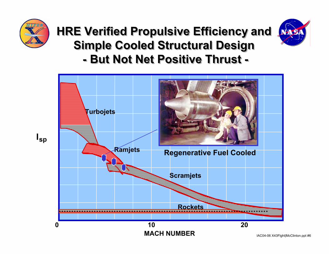
Regenerative Fuel Cooled
HRE Verified Propulsive Efficiency and Simple Cooled Structural Design
- But Not Net Positive Thrust -
HRE Verified Propulsive Efficiency and Simple Cooled Structural Design
- But Not Net Positive Thrust -
IAC04-06 X43Flght|McClinton.ppt #7
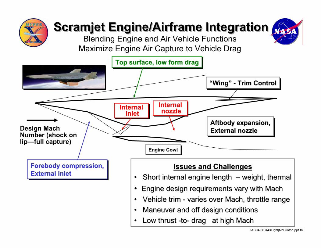
Design MachNumber (shock on lip—full capture)
Forebody compression,Forebody compression,External inletExternal inlet
Aftbody expansion,Aftbody expansion,External nozzleExternal nozzle
Top surface, low form dragTop surface, low form drag
Engine CowlEngine Cowl
““WingWing”” -- Trim ControlTrim Control
Issues and ChallengesIssues and Challenges•• Short internal engine length Short internal engine length –– weight, thermalweight, thermal•• Engine design requirements vary with MachEngine design requirements vary with Mach•• Vehicle trim Vehicle trim -- varies over Mach, throttle rangevaries over Mach, throttle range•• Maneuver and off design conditions Maneuver and off design conditions •• Low thrust Low thrust --toto-- drag at high Machdrag at high Mach
InternalInternalinletinlet
InternalInternalnozzlenozzle
Blending Engine and Air Vehicle FunctionsMaximize Engine Air Capture to Vehicle Drag
Scramjet Engine/Airframe IntegrationScramjet Engine/Airframe Integration
IAC04-06 X43Flght|McClinton.ppt #8
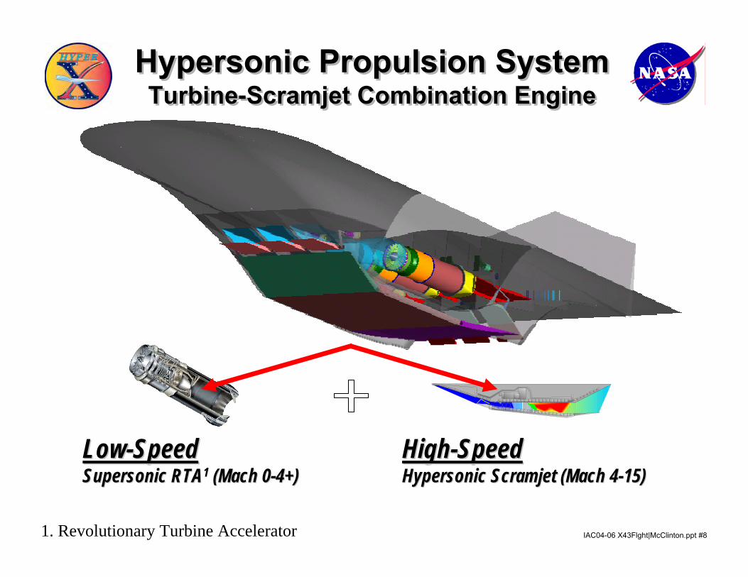
LowLow--Speed Speed Supersonic RTASupersonic RTA11 (Mach 0(Mach 0--4+)4+)
HighHigh--Speed Speed Hypersonic Scramjet (Mach 4Hypersonic Scramjet (Mach 4--15)15)
LRC
1. Revolutionary Turbine Accelerator
Hypersonic Propulsion SystemTurbine-Scramjet Combination Engine
Hypersonic Propulsion SystemTurbine-Scramjet Combination Engine
IAC04-06 X43Flght|McClinton.ppt #9IAC04-06 X43Flght|McClinton.ppt #10
NASA HypersonicsNASA Hypersonics
1965-74H2 Fuel/ Cooled
Variable Geom SJ
1970-82H2 Fixed Geom3-Generations
1994-97CIAM-NASA Fight
H2 M 3-6.5
Fully 3-D Technology
1980-84HC Fixed Geom3-generations
1996-Today Hyper-X
X-43
X-43 LS
1995-2004 SLIH2 and H/CTSTO and
TBCC & RBCCAirframe and Propulsion
1984-94 NASPDesign, TestTechnologyH2 fueled
NASA Hypersonics NASA Hypersonics
1996-2003 NGLT
1996-2005 Hyper-X
IAC04-06 X43Flght|McClinton.ppt #10
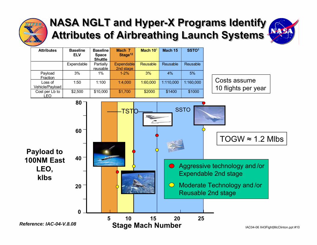
NASA NGLT and Hyper-X Programs Identify Attributes of Airbreathing Launch SystemsNASA NGLT and Hyper-X Programs Identify Attributes of Airbreathing Launch Systems
Costs assume 10 flights per year
Attributes BaselineELV
BaselineSpaceShuttle
Mach 7Stage12
Mach 101 Mach 15 SSTO1
Expendable Partiallyreusable
Expendable2nd stage
Reusable Reusable Reusable
PayloadFraction
3% 1% 1-2% 3% 4% 5%
Loss ofVehicle/Payload
1:50 1:100 1:4,000 1:60,000 1:110,000 1:160,000
Cost per Lb toLEO
$2,500 $10,000 $1,700 $2000 $1400 $1000
Payload to 100NM East
LEO,klbs
5
SSTO
Stage Mach Number
––––TSTO––––
10 15 20 25
20
40
60
0
80
Aggressive technology and /orExpendable 2nd stage
Moderate Technology and /orReusable 2nd stage
Reference: IAC-04-V.8.08
TOGW ≈ 1.2 Mlbs
IAC04-06 X43Flght|McClinton.ppt #11
Relative $/lb Payload100%
23%11%
1%0%
20%
40%
60%
80%
100%
120%
Shuttle Two StageAirbreather
Single StageAirbreather
Airline
Architecture
Flexibility Analysis Cross Range Example
AirbreatherAbort Footprint
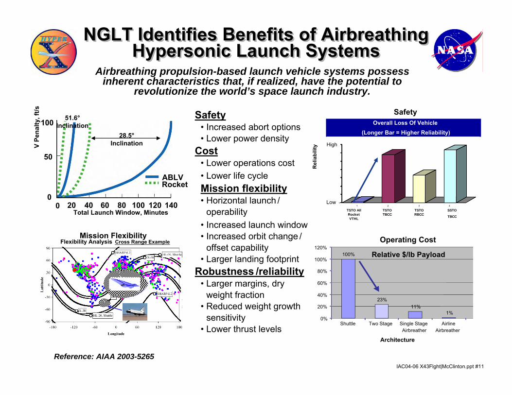
Safety• Increased abort options• Lower power density
Cost• Lower operations cost• Lower life cycleMission flexibility• Horizontal launch /
operability• Increased launch window• Increased orbit change /
offset capability• Larger landing footprint
Robustness /reliability• Larger margins, dry
weight fraction• Reduced weight growth
sensitivity• Lower thrust levels
Operating Cost
Safety
Mission Flexibility
Rel
iabi
lity
(1 in
odd
s of
Los
s of
Veh
icle
)
Overall Loss Of Vehicle(Longer Bar = Higher Reliability)
0
20000
40000
60000
80000
100000
120000
140000
1 2 3 4
TSTO AllRocketVTHL
TSTOTBCC
TSTORBCC
SSTO
TBCC
Low
High
NGLT Identifies Benefits of Airbreathing Hypersonic Launch Systems
NGLT Identifies Benefits of Airbreathing Hypersonic Launch Systems
Reference: AIAA 2003-5265
V Pe
nalty
, ft/s
100
50
00 20 40 60 80 100 120 140
Rocket
Total Launch Window, Minutes
ABLV
28.5°Inclination
51.6°Inclination
Airbreathing propulsion-based launch vehicle systems possess inherent characteristics that, if realized, have the potential to
revolutionize the world’s space launch industry.
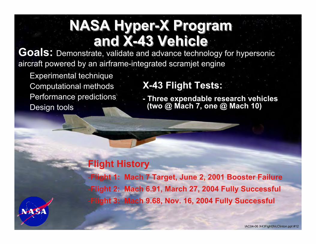
NASA Hyper-X Program and X-43 Vehicle
NASA Hyper-X Program and X-43 Vehicle
Goals: Demonstrate, validate and advance technology for hypersonic aircraft powered by an airframe-integrated scramjet engine
X-43 Flight Tests:- Three expendable research vehicles(two @ Mach 7, one @ Mach 10)
IAC04-06 X43Flght|McClinton.ppt #12
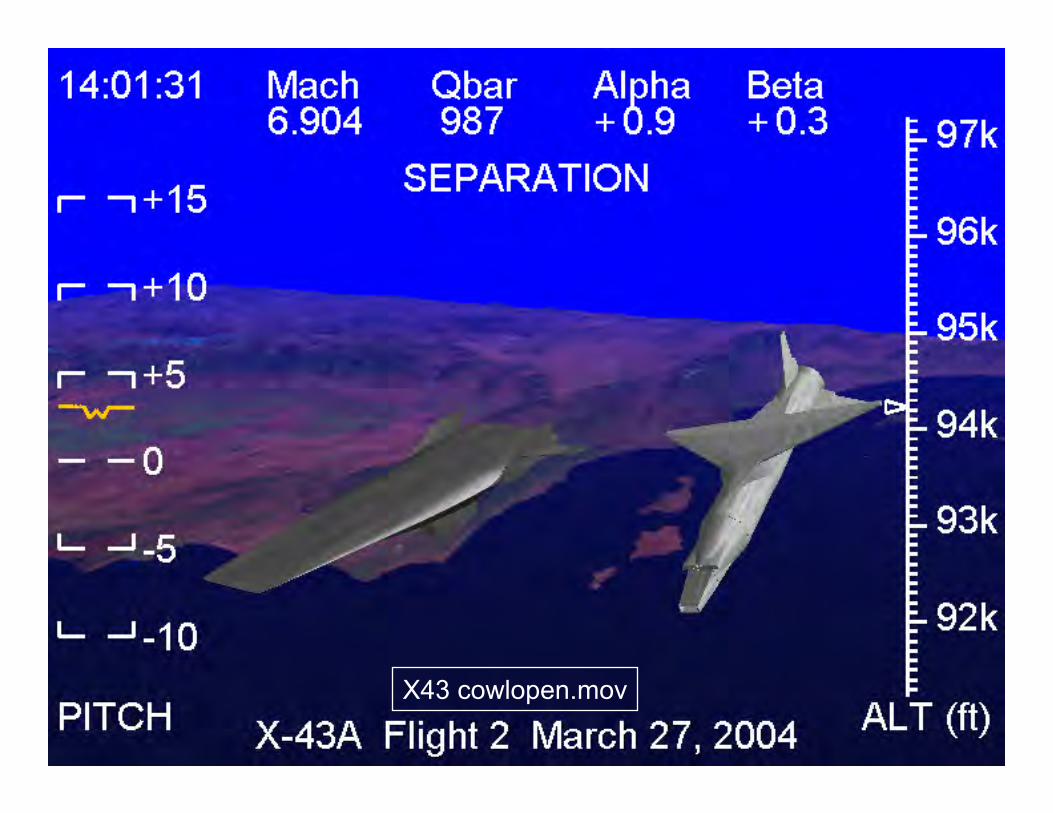
Flight History-Flight 1: Mach 7 Target, June 2, 2001 Booster Failure-Flight 2: Mach 6.91, March 27, 2004 Fully Successful-Flight 3: Mach 9.68, Nov. 16, 2004 Fully Successful
Experimental techniqueComputational methodsPerformance predictions Design tools

IAC04-06 X43Flght|McClinton.ppt #13
X-43 Research VehicleX-43 Research Vehicle
“Vision” Vehicle“Vision” Vehicle
X-43 Derived from MDC/P&W Dual-Fuel, Global Reach Study
IAC04-06 X43Flght|McClinton.ppt #14
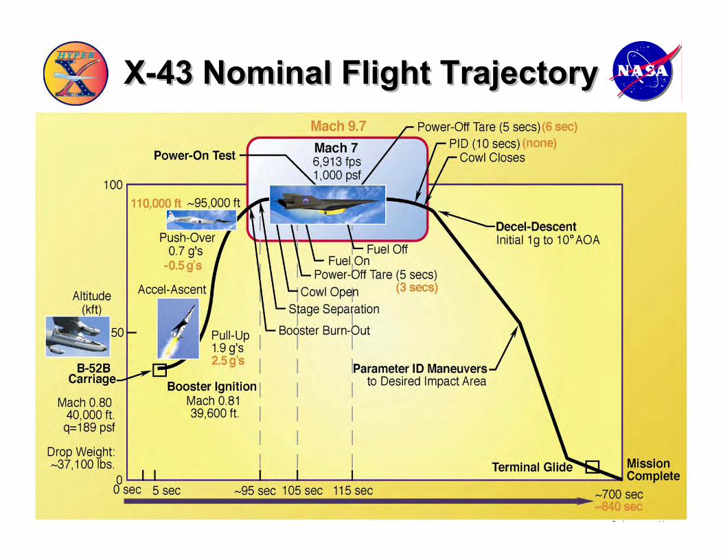
X-43 Nominal Flight TrajectoryX-43 Nominal Flight Trajectory
IAC04-06 X43Flght|McClinton.ppt #15
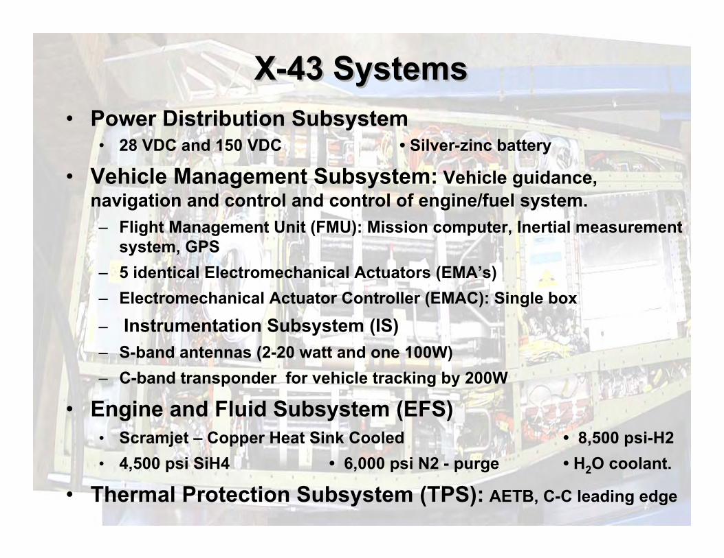
X-43 SystemsX-43 Systems• Power Distribution Subsystem
• 28 VDC and 150 VDC • Silver-zinc battery
• Vehicle Management Subsystem: Vehicle guidance, navigation and control and control of engine/fuel system. – Flight Management Unit (FMU): Mission computer, Inertial measurement
system, GPS– 5 identical Electromechanical Actuators (EMA’s)– Electromechanical Actuator Controller (EMAC): Single box– Instrumentation Subsystem (IS)– S-band antennas (2-20 watt and one 100W)– C-band transponder for vehicle tracking by 200W
• Engine and Fluid Subsystem (EFS)• Scramjet – Copper Heat Sink Cooled • 8,500 psi-H2• 4,500 psi SiH4 • 6,000 psi N2 - purge • H2O coolant.
• Thermal Protection Subsystem (TPS): AETB, C-C leading edge

IAC04-06 X43Flght|McClinton.ppt #16
X-43 Internal LayoutX-43 Internal Layout
Rudder N2 Controller Fads PPTs
H2O
Wings SiH4 H2
BatteryFMU
Actuator
Instrumentation System
IAC04-06 X43Flght|McClinton.ppt #17
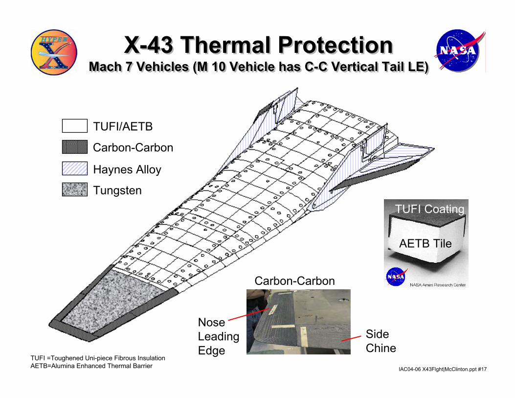
X-43 Thermal ProtectionMach 7 Vehicles (M 10 Vehicle has C-C Vertical Tail LE)
X-43 Thermal ProtectionMach 7 Vehicles (M 10 Vehicle has C-C Vertical Tail LE)
Carbon-Carbon
TUFI/AETB
Haynes Alloy
Tungsten
AETB Tile
TUFI Coating
TUFI =Toughened Uni-piece Fibrous InsulationAETB=Alumina Enhanced Thermal Barrier
NoseLeadingEdge
SideChine
Carbon-Carbon
IAC04-06 X43Flght|McClinton.ppt #18
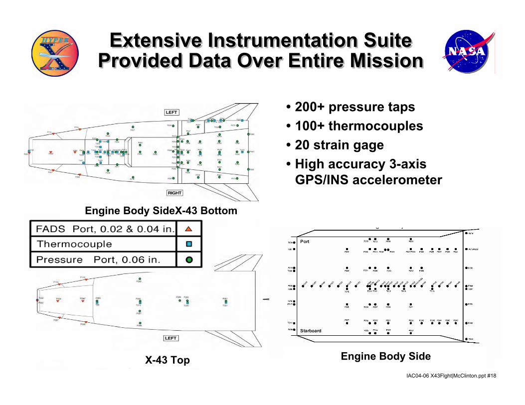
Extensive Instrumentation SuiteProvided Data Over Entire MissionExtensive Instrumentation Suite
Provided Data Over Entire Mission
• 200+ pressure taps • 100+ thermocouples • 20 strain gage• High accuracy 3-axis
GPS/INS accelerometer
Engine Body SideX-43 Top
Engine Body SideX-43 Bottom
IAC04-06 X43Flght|McClinton.ppt #19IAC04-06 X43Flght|McClinton.ppt #19B52.mov
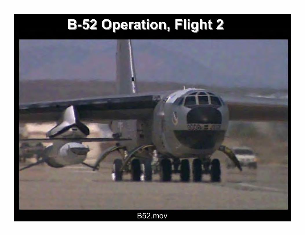
B-52 Operation, Flight 2B-52 Operation, Flight 2
IAC04-06 X43Flght|McClinton.ppt #20
LaunchP1.mov
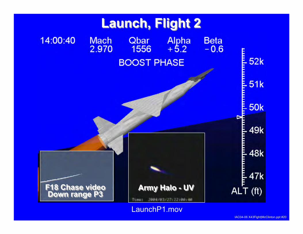
Launch, Flight 2Launch, Flight 2
F18 Chase videoDown range P3
F18 Chase videoDown range P3
Army Halo - UVArmy Halo - UV
IAC04-06 X43Flght|McClinton.ppt #21
R
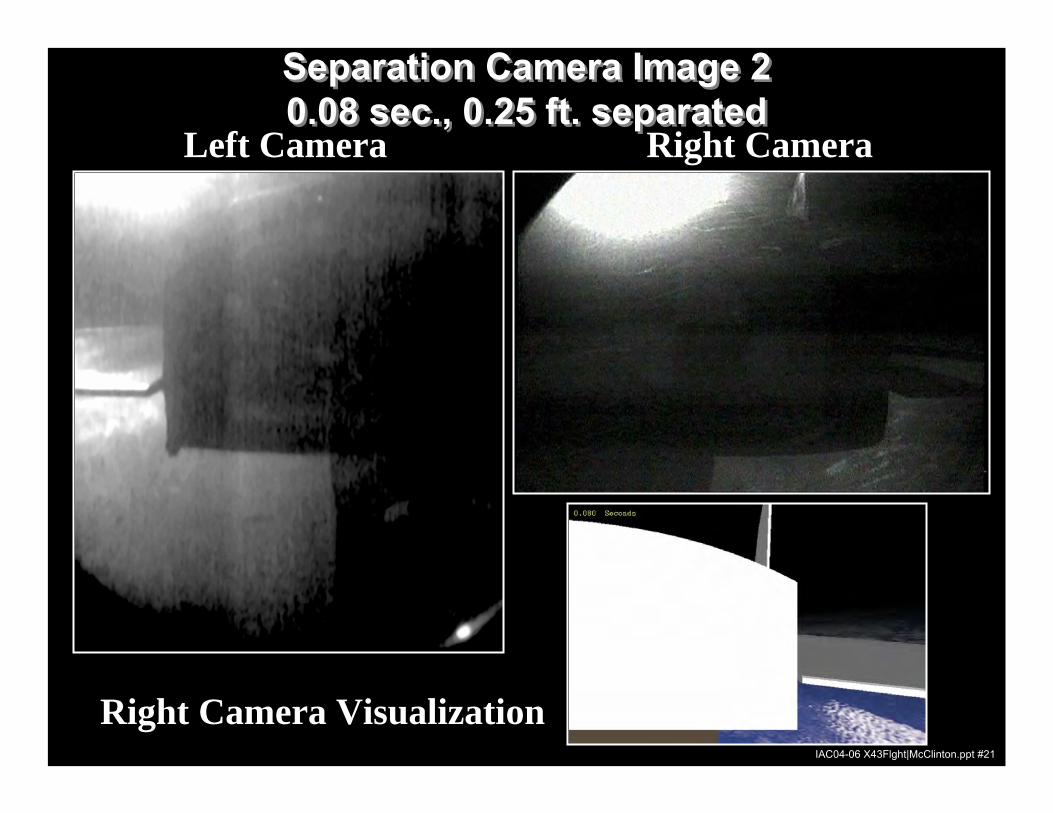
Separation Camera Image 2 0.08 sec., 0.25 ft. separatedSeparation Camera Image 2 0.08 sec., 0.25 ft. separated
Right CameraLeft Camera
Right Camera Visualization IAC04-06 X43Flght|McClinton.ppt #21
IAC04-06 X43Flght|McClinton.ppt #22
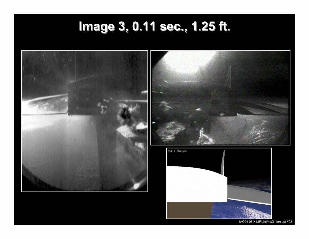
Image 3, 0.11 sec., 1.25 ft.Image 3, 0.11 sec., 1.25 ft.
IAC04-06 X43Flght|McClinton.ppt #22
IAC04-06 X43Flght|McClinton.ppt #23
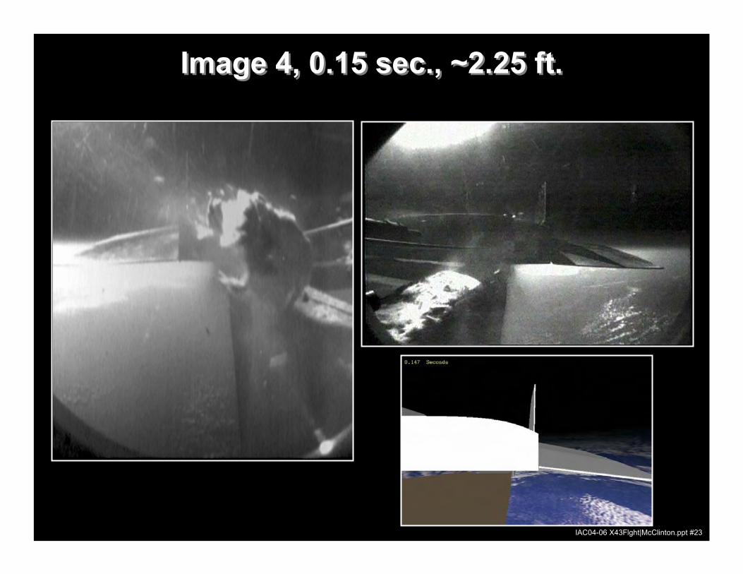
Image 4, 0.15 sec., ~2.25 ft.Image 4, 0.15 sec., ~2.25 ft.
IAC04-06 X43Flght|McClinton.ppt #23

IAC04-06 X43Flght|McClinton.ppt #24
Image 5, 0.18 sec., ~3.25 ft.Image 5, 0.18 sec., ~3.25 ft.
IAC04-06 X43Flght|McClinton.ppt #24
IAC04-06 X43Flght|McClinton.ppt #25
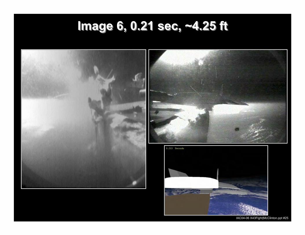
Image 6, 0.21 sec, ~4.25 ftImage 6, 0.21 sec, ~4.25 ft
IAC04-06 X43Flght|McClinton.ppt #25
IAC04-06 X43Flght|McClinton.ppt #26
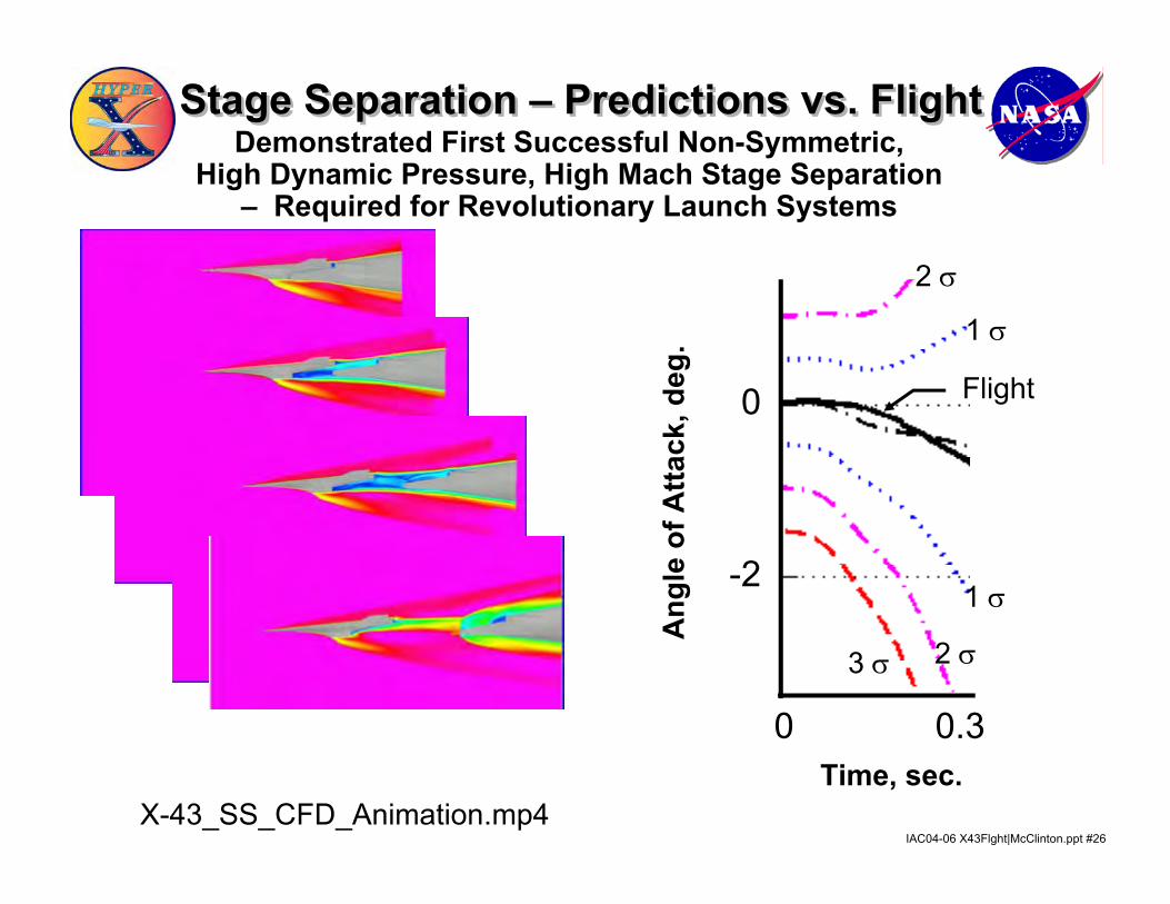
Stage Separation – Predictions vs. FlightStage Separation – Predictions vs. FlightDemonstrated First Successful Non-Symmetric,
High Dynamic Pressure, High Mach Stage Separation – Required for Revolutionary Launch Systems
0 0.50 0.3
0
-2
X-43_SS_CFD_Animation.mp4Time, sec.
Ang
le o
f Atta
ck, d
eg. 1 σ
2 σ
1 σ
2 σ3 σ
Flight
IAC04-06 X43Flght|McClinton.ppt #27IAC04-06 X43Flght|McClinton.ppt #27
X43 cowlopen.mov
IAC04-06 X43Flght|McClinton.ppt #28
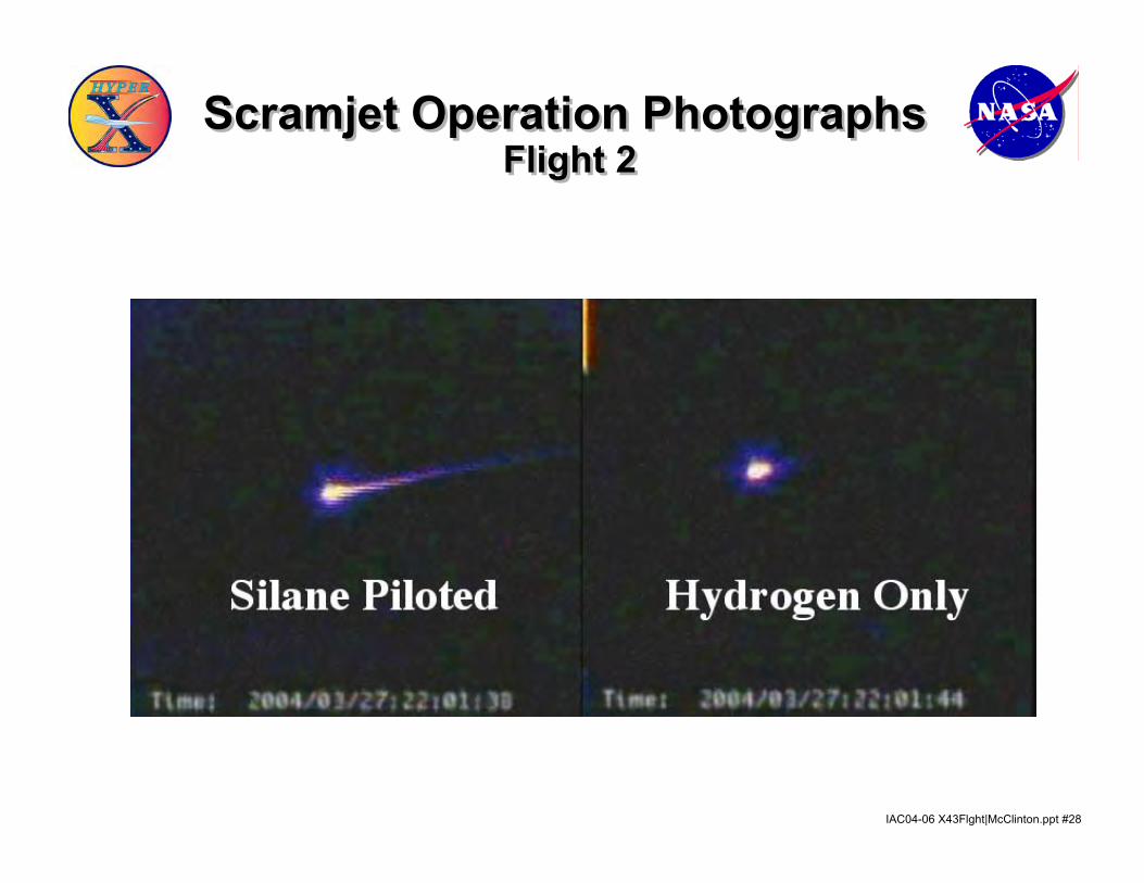
Scramjet Operation PhotographsScramjet Operation PhotographsFlight 2Flight 2
IAC04-06 X43Flght|McClinton.ppt #29
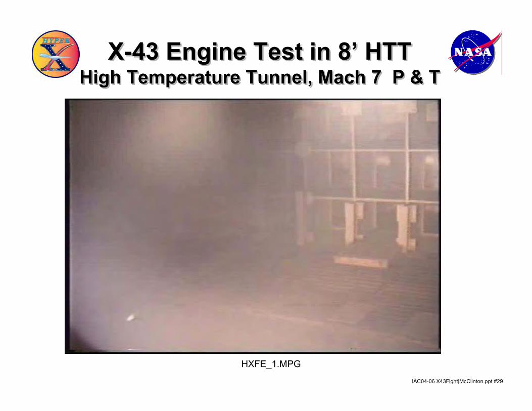
HXFE_1.MPG
X-43 Engine Test in 8’ HTTHigh Temperature Tunnel, Mach 7 P & T
X-43 Engine Test in 8’ HTTHigh Temperature Tunnel, Mach 7 P & T
IAC04-06 X43Flght|McClinton.ppt #30
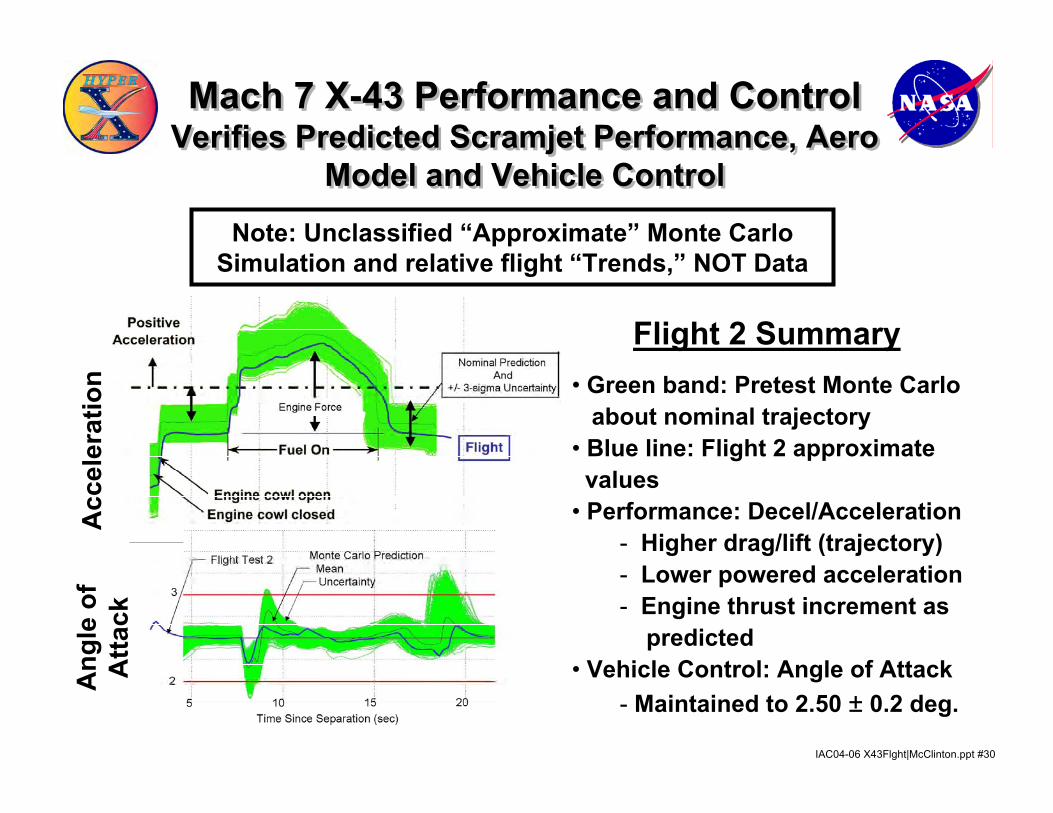
Note: Unclassified “Approximate” Monte Carlo Simulation and relative flight “Trends,” NOT Data
Mach 7 X-43 Performance and ControlVerifies Predicted Scramjet Performance, Aero
Model and Vehicle Control
Mach 7 X-43 Performance and ControlVerifies Predicted Scramjet Performance, Aero
Model and Vehicle Control
• Green band: Pretest Monte Carloabout nominal trajectory
• Blue line: Flight 2 approximatevalues
• Performance: Decel/Acceleration- Higher drag/lift (trajectory)- Lower powered acceleration- Engine thrust increment as
predicted• Vehicle Control: Angle of Attack
- Maintained to 2.50 ± 0.2 deg.
Acc
eler
atio
nA
ngle
of
Atta
ck
Flight 2 Summary

IAC04-06 X43Flght|McClinton.ppt #31
• Green band: Pretest Monte Carlouncertainty about nominal
• Blue/Dashed line: Flight 3• Acceleration
- Higher drag/lift (trajectory)- Lower powered acceleration
than predicted- Engine thrust increment as
predictedAngle of Attack- Maintained to 1.0 ± 0.2 deg.during powered flight
Flight 3 Summary
Mach 10 X-43 Performance and ControlVerifies Predicted Scramjet Performance,
Aero Model and Vehicle Control
Mach 10 X-43 Performance and ControlVerifies Predicted Scramjet Performance,
Aero Model and Vehicle ControlNote: Unclassified “Approximate” Monte Carlo
Simulation and relative flight “Trends,” NOT Data
IAC04-06 X43Flght|McClinton.ppt #32
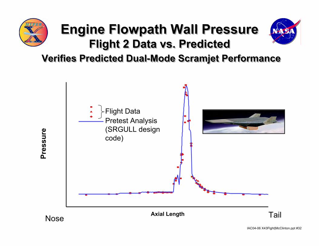
Engine Flowpath Wall Pressure Flight 2 Data vs. Predicted
Verifies Predicted Dual-Mode Scramjet Performance
Engine Flowpath Wall Pressure Flight 2 Data vs. Predicted
Verifies Predicted Dual-Mode Scramjet Performance
Axial Length
SUR
FAC
EPR
E SSU
RE
Pres
sure
Flight DataPretest Analysis(SRGULL designcode)
Nose Tail
IAC04-06 X43Flght|McClinton.ppt #33
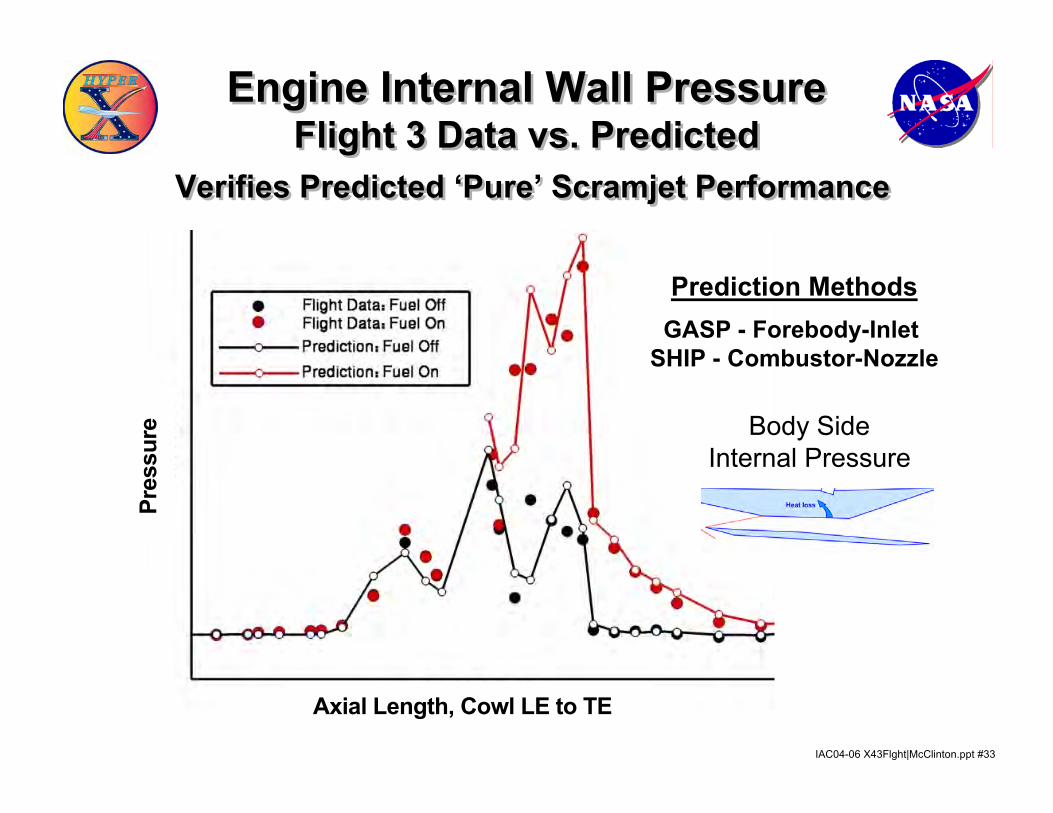
Engine Internal Wall Pressure Flight 3 Data vs. Predicted
Verifies Predicted ‘Pure’ Scramjet Performance
Engine Internal Wall Pressure Flight 3 Data vs. Predicted
Verifies Predicted ‘Pure’ Scramjet Performance
Axial Length, Cowl LE to TE
Pres
sure
Prediction MethodsGASP - Forebody-Inlet
SHIP - Combustor-Nozzle
Body SideInternal Pressure
IAC04-06 X43Flght|McClinton.ppt #34
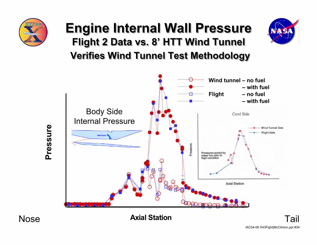
Engine Internal Wall Pressure Flight 2 Data vs. 8’ HTT Wind TunnelVerifies Wind Tunnel Test Methodology
Engine Internal Wall Pressure Flight 2 Data vs. 8’ HTT Wind TunnelVerifies Wind Tunnel Test Methodology
g
Axial Station
Pre s
sure
Wind tunnel Š no fuelWind tunnel Š with fuelFlight Š no fuelFlight Š with fuel
Pres
sure
Nose Tail
Wind tunnel – no fuel– with fuel
Flight – no fuel– with fuel
Body SideInternal Pressure
IAC04-06 X43Flght|McClinton.ppt #35
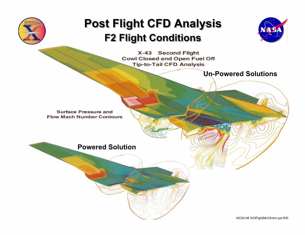
Post Flight CFD Analysis F2 Flight Conditions
Post Flight CFD Analysis F2 Flight Conditions
Powered Solution
Un-Powered Solutions
IAC04-06 X43Flght|McClinton.ppt #36
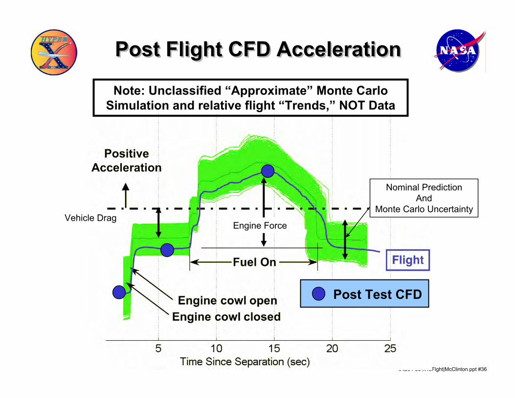
Post Flight CFD Acceleration Post Flight CFD Acceleration
Engine ForceVehicle Drag
Nominal PredictionAnd
Monte Carlo Uncertainty
Note: Unclassified “Approximate” Monte Carlo Simulation and relative flight “Trends,” NOT Data
Post Test CFD
IAC04-06 X43Flght|McClinton.ppt #37
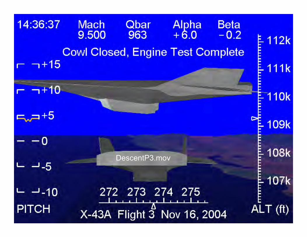
DescentP3.mov
IAC04-06 X43Flght|McClinton.ppt #38
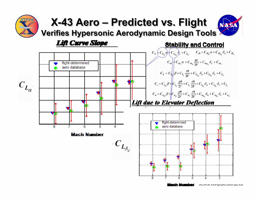
X-43 Aero – Predicted vs. FlightVerifies Hypersonic Aerodynamic Design Tools
X-43 Aero – Predicted vs. FlightVerifies Hypersonic Aerodynamic Design Tools
IAC04-06 X43Flght|McClinton.ppt #39
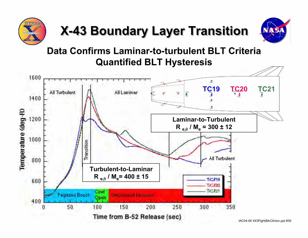
TC19 TC20 TC21
Laminar-to-TurbulentR e,θ / Me = 300 ± 12
Turbulent-to-LaminarR e,θ / Me= 400 ± 15
X-43 Boundary Layer Transition X-43 Boundary Layer Transition Data Confirms Laminar-to-turbulent BLT Criteria
Quantified BLT Hysteresis
IAC04-06 X43Flght|McClinton.ppt #40
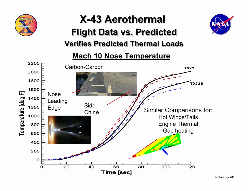
X-43 AerothermalFlight Data vs. Predicted
Verifies Predicted Thermal Loads
X-43 AerothermalFlight Data vs. Predicted
Verifies Predicted Thermal Loads
NoseLeadingEdge Side
Chine
Carbon-Carbon
Similar Comparisons for:Hot Wings/TailsEngine Thermal
Gap heating
Mach 10 Nose Temperature
IAC04-06 X43Flght|McClinton.ppt #41
-0.8
-0.6
-0.4
-0.2
0
0.2
0.4
0 0.2 0.4 0.6 0.8 1
NormalAccel(g's)
time (sec)
p = .27 - .15 = .12 secf = 1/.12 = 8.33 Hz.
p = .87 - .76 = .11 secf = 1./.11 sec = 9 Hz.
-0.8
-0.6
-0.4
-0.2
0
0.2
0.4
2 2.2 2.4 2.6 2.8 3
NormalAccel(g's)
time (sec)
p = 2.32 - 2.2 = .12 secf = 1/p = 8.33 Hz.
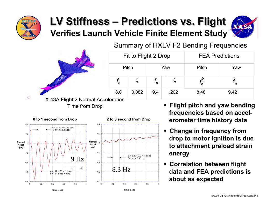
X-43A Flight 2 Normal AccelerationTime from Drop
0 to 1 second from Drop 2 to 3 second from Drop
9 Hz8.3 Hz
Ź Ź
8.0 0.082 9.4 .202 8.48 9.42
Fit to Flight 2 Drop FEA Predictions
Pitch Yaw Pitch Yaw
fn ζ fn ζ fnfn
Summary of HXLV F2 Bending Frequencies
• Flight pitch and yaw bendingfrequencies based on accel-erometer time history data
• Change in frequency from drop to motor ignition is due to attachment preload strain energy
• Correlation between flight data and FEA predictions is about as expected
LV Stiffness – Predictions vs. FlightLV Stiffness – Predictions vs. FlightVerifies Launch Vehicle Finite Element Study
IAC04-06 X43Flght|McClinton.ppt #42
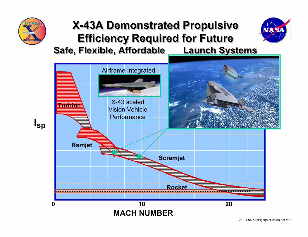
Turbine
Scramjet
Ramjet
0 10 20MACH NUMBER
Isp
Rocket
X-43 scaledVision VehiclePerformance
Airframe Integrated
X-43A Demonstrated Propulsive Efficiency Required for Future
Safe, Flexible, Affordable Launch Systems
X-43A Demonstrated Propulsive Efficiency Required for Future
Safe, Flexible, Affordable Launch Systems
IAC04-06 X43Flght|McClinton.ppt #43
Summary Of Integrated Hypersonic Vehicle Performance
Summary Of Integrated Hypersonic Vehicle Performance
• X-43 airframe drag (and lift) was slightly higher than nominal predicted, but within uncertainty prediction
• Scramjet engine performance was very close to preflight predictions (positive acceleration for M 7, Cruise for M 10)
• Control deflections to trim engine induced moments were very close to preflight predictions
• Other hypersonic vehicle technologies were as predicted─ Aerodynamic stability and control─ Natural and Tripped boundary layer transition─ Airframe and wing structure─ Thermal loads/Gap heating─ TPS─ Internal environment─ Launch vehicle stiffness
IAC04-06 X43Flght|McClinton.ppt #44
X-43 Technology AchievementsX-43 Technology Achievements
• Firsts─ Flight of scramjet powered vehicle ─ Successful high dynamic pressure, high Mach, non-
symmetrical stage separation (required for TSTO)• Verified performance, operability and controllability
─ Airframe-integrated Scramjet─ Integrated, powered, hypersonic airbreathing Vehicle
• Verified engineering application of NASA-Industry-University hypersonic vehicle design tools
Tools Disciplines Physics- Experimental - Analysis
CFD - NumericalAnalyticalEmpirical
- MDOE for engine/vehicle design optimization
- Propulsion- Aerodynamic- Structural- Thermal- Boundary layer transition- Flight and engine controls- Vehicle synthesis
IAC04-06 X43Flght|McClinton.ppt #45
• Natural and forced boundary layer transition• Turbulence• Separation caused by shock-boundary layer interaction• Shock-shock interaction heating (Type 3 and 4)• Isolator shock trains• Cold-wall heat transfer• Fuel injection, penetration and mixing• Finite rate chemical kinetics• Turbulence-chemistry interaction• Boundary layer relaminarization• Recombination chemistry• Catalytic wall effects
- Most of these phenomena were modeled in the design tools. Some were avoided by application of a uncertainty factors.
- X-43 success demonstrates an engineering level understanding of “the physics”. A better understanding of these issues will be beneficial for optimization of vehicle performance, but not “enabling”- All designs share the same physics
Hypersonic Physics - PropulsionHypersonic Physics - Propulsion

IAC04-06 X43Flght|McClinton.ppt #46
Guinness World Record The fastest jet-powered aircraft is NASA’s X- 43A,
which achieved Mach 6.9 on 27 March 2004 in a flight lasting 11 seconds while covering 15 miles over the Pacific Ocean
Guinness World Record The fastest jet-powered aircraft is NASA’s X- 43A,
which achieved Mach 6.9 on 27 March 2004 in a flight lasting 11 seconds while covering 15 miles over the Pacific Ocean
IAC04-06 X43Flght|McClinton.ppt #47
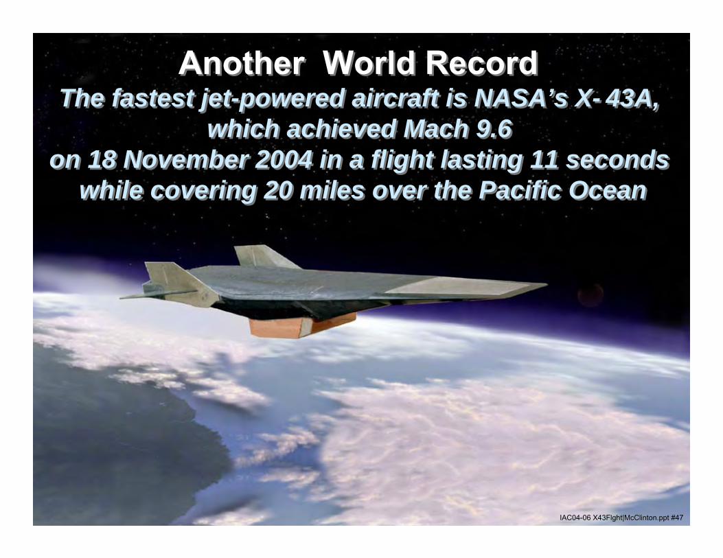
Another World Record The fastest jet-powered aircraft is NASA’s X- 43A,
which achieved Mach 9.6 on 18 November 2004 in a flight lasting 11 seconds
while covering 20 miles over the Pacific Ocean
Another World Record The fastest jet-powered aircraft is NASA’s X- 43A,
which achieved Mach 9.6 on 18 November 2004 in a flight lasting 11 seconds
while covering 20 miles over the Pacific Ocean
IAC04-06 X43Flght|McClinton.ppt #48
“Cowl Closed!!”“Cowl Closed!!”
IAC04-06 X43Flght|McClinton.ppt #49
Assessment of Hypersonic Airbreathing Technology Readiness
Assessment of Hypersonic Airbreathing Technology Readiness
Considering X-43 Accomplishments–
What is the Status of Hypersonic Technology??
and
What should we do next???
Considering X-43 Accomplishments–
What is the Status of Hypersonic Technology??
and
What should we do next???
IAC04-06 X43Flght|McClinton.ppt #50
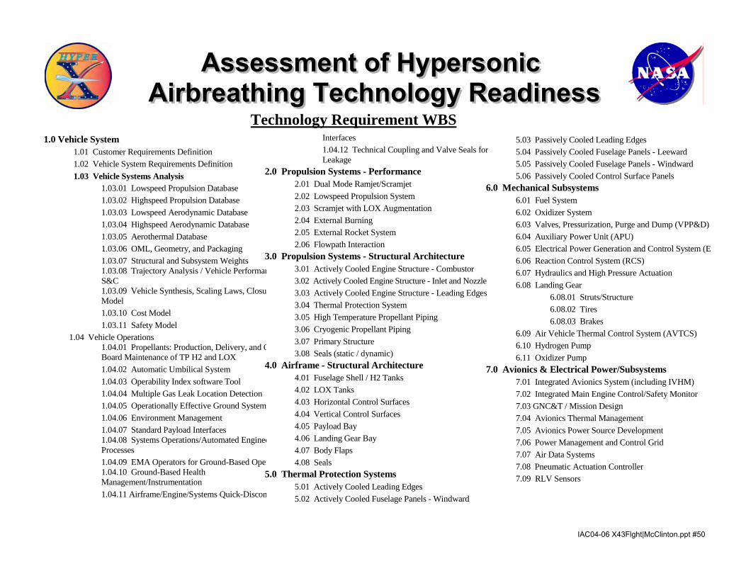
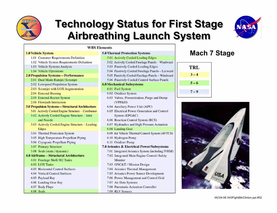
Technology Requirement WBS
1.0 Vehicle System 1.01 Customer Requirements Definition 1.02 Vehicle System Requirements Definition 1.03 Vehicle Systems Analysis 1.03.01 Lowspeed Propulsion Database 1.03.02 Highspeed Propulsion Database 1.03.03 Lowspeed Aerodynamic Database 1.03.04 Highspeed Aerodynamic Database 1.03.05 Aerothermal Database 1.03.06 OML, Geometry, and Packaging 1.03.07 Structural and Subsystem Weights
1.03.08 Trajectory Analysis / Vehicle PerformanS&C
1.03.09 Vehicle Synthesis, Scaling Laws, ClosurModel
1.03.10 Cost Model 1.03.11 Safety Model 1.04 Vehicle Operations
1.04.01 Propellants: Production, Delivery, and OBoard Maintenance of TP H2 and LOX
1.04.02 Automatic Umbilical System 1.04.03 Operability Index software Tool 1.04.04 Multiple Gas Leak Location Detection 1.04.05 Operationally Effective Ground Systems 1.04.06 Environment Management 1.04.07 Standard Payload Interfaces
1.04.08 Systems Operations/Automated EngineeProcesses
1.04.09 EMA Operators for Ground-Based Oper
1.04.10 Ground-Based Health Management/Instrumentation
1.04.11 Airframe/Engine/Systems Quick-Discon
Interfaces
1.04.12 Technical Coupling and Valve Seals forLeakage
2.0 Propulsion Systems - Performance 2.01 Dual Mode Ramjet/Scramjet 2.02 Lowspeed Propulsion System 2.03 Scramjet with LOX Augmentation 2.04 External Burning 2.05 External Rocket System 2.06 Flowpath Interaction 3.0 Propulsion Systems - Structural Architecture 3.01 Actively Cooled Engine Structure - Combustor 3.02 Actively Cooled Engine Structure - Inlet and Nozzle 3.03 Actively Cooled Engine Structure - Leading Edges 3.04 Thermal Protection System 3.05 High Temperature Propellant Piping 3.06 Cryogenic Propellant Piping 3.07 Primary Structure 3.08 Seals (static / dynamic) 4.0 Airframe - Structural Architecture 4.01 Fuselage Shell / H2 Tanks 4.02 LOX Tanks 4.03 Horizontal Control Surfaces 4.04 Vertical Control Surfaces 4.05 Payload Bay 4.06 Landing Gear Bay 4.07 Body Flaps 4.08 Seals 5.0 Thermal Protection Systems 5.01 Actively Cooled Leading Edges 5.02 Actively Cooled Fuselage Panels - Windward
5.03 Passively Cooled Leading Edges 5.04 Passively Cooled Fuselage Panels - Leeward 5.05 Passively Cooled Fuselage Panels - Windward 5.06 Passively Cooled Control Surface Panels 6.0 Mechanical Subsystems 6.01 Fuel System 6.02 Oxidizer System 6.03 Valves, Pressurization, Purge and Dump (VPP&D) 6.04 Auxiliary Power Unit (APU) 6.05 Electrical Power Generation and Control System (EP 6.06 Reaction Control System (RCS) 6.07 Hydraulics and High Pressure Actuation 6.08 Landing Gear 6.08.01 Struts/Structure 6.08.02 Tires 6.08.03 Brakes 6.09 Air Vehicle Thermal Control System (AVTCS) 6.10 Hydrogen Pump 6.11 Oxidizer Pump 7.0 Avionics & Electrical Power/Subsystems 7.01 Integrated Avionics System (including IVHM) 7.02 Integrated Main Engine Control/Safety Monitor 7.03 GNC&T / Mission Design 7.04 Avionics Thermal Management 7.05 Avionics Power Source Development 7.06 Power Management and Control Grid 7.07 Air Data Systems 7.08 Pneumatic Actuation Controller 7.09 RLV Sensors
Assessment of Hypersonic Airbreathing Technology Readiness
Assessment of Hypersonic Airbreathing Technology Readiness
IAC04-06 X43Flght|McClinton.ppt #51
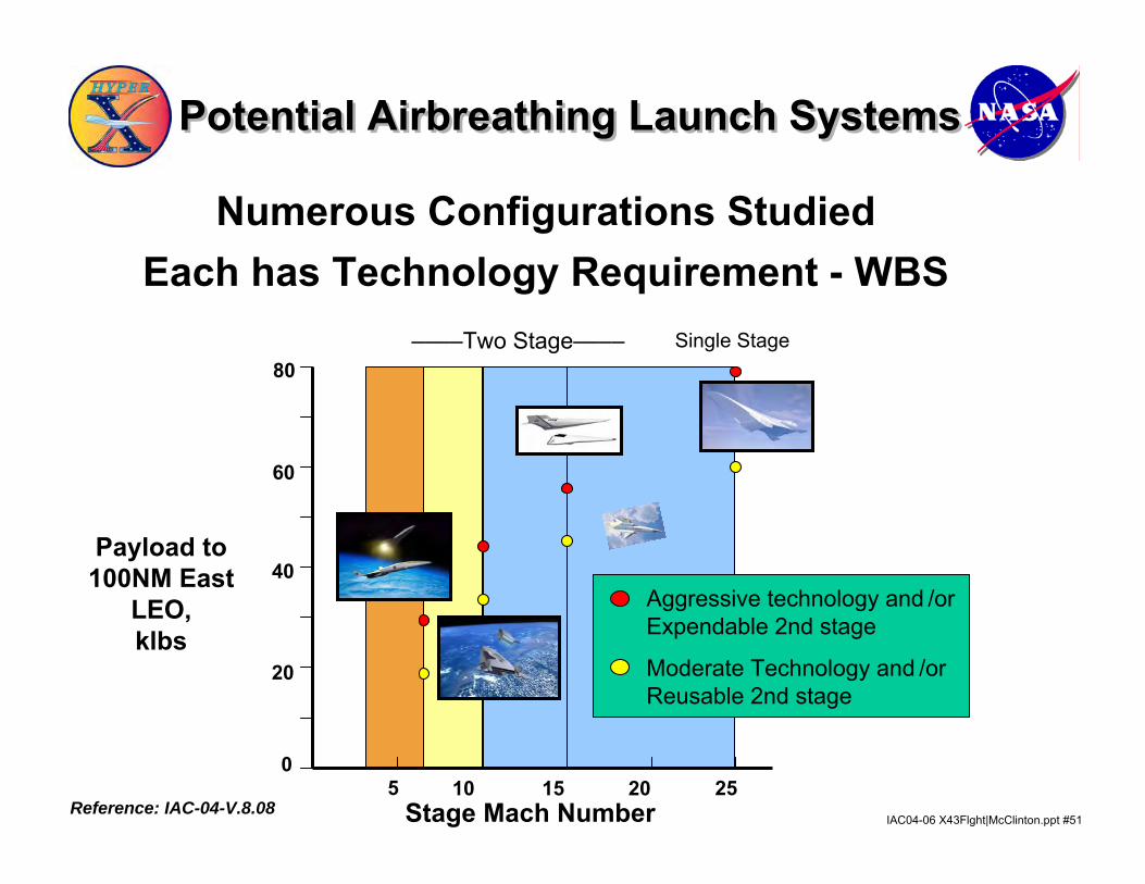
Payload to 100NM East
LEO,klbs
5
Single Stage
Stage Mach Number
––––Two Stage––––
10 15 20 25
20
40
60
0
80
Aggressive technology and /orExpendable 2nd stage
Moderate Technology and /orReusable 2nd stage
Potential Airbreathing Launch SystemsPotential Airbreathing Launch Systems
Reference: IAC-04-V.8.08
Numerous Configurations StudiedEach has Technology Requirement - WBS
IAC04-06 X43Flght|McClinton.ppt #52
Technology Status for First StageAirbreathing Launch System
Technology Status for First StageAirbreathing Launch System
Mach 7 Stage
IAC04-06 X43Flght|McClinton.ppt #53
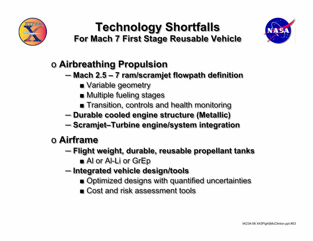
Technology ShortfallsFor Mach 7 First Stage Reusable Vehicle
Technology ShortfallsFor Mach 7 First Stage Reusable Vehicle
ס Airbreathing Propulsion─ Mach 2.5 – 7 ram/scramjet flowpath definition
■ Variable geometry■ Multiple fueling stages■ Transition, controls and health monitoring
─ Durable cooled engine structure (Metallic)─ Scramjet–Turbine engine/system integration
ס Airframe─ Flight weight, durable, reusable propellant tanks
■ Al or Al-Li or GrEp─ Integrated vehicle design/tools
■ Optimized designs with quantified uncertainties■ Cost and risk assessment tools
IAC04-06 X43Flght|McClinton.ppt #54
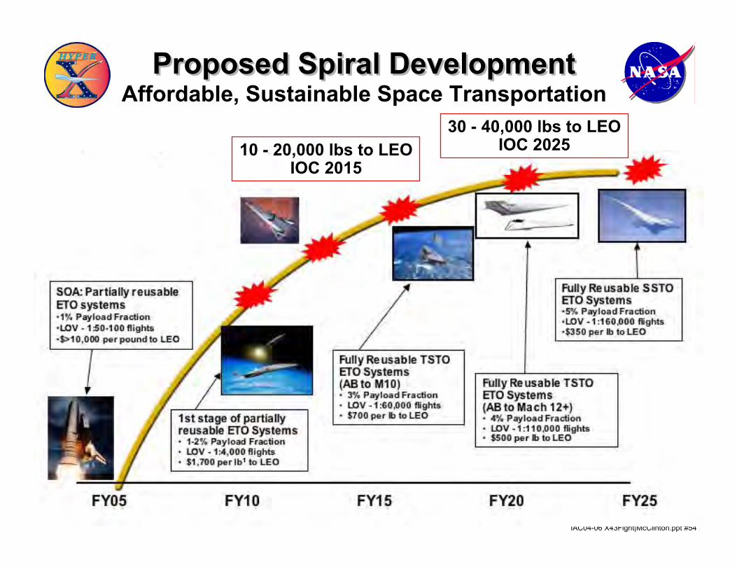
Affordable, Sustainable Space Transportation
10 - 20,000 lbs to LEOIOC 2015
30 - 40,000 lbs to LEOIOC 2025
Proposed Spiral DevelopmentProposed Spiral Development
IAC04-06 X43Flght|McClinton.ppt #55
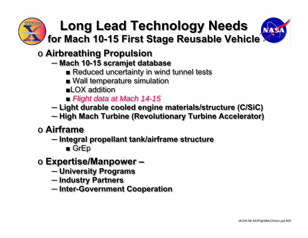
Long Lead Technology Needsfor Mach 10-15 First Stage Reusable Vehicle
Long Lead Technology Needsfor Mach 10-15 First Stage Reusable Vehicle
ס Airbreathing Propulsion─ Mach 10-15 scramjet database
■ Reduced uncertainty in wind tunnel tests■ Wall temperature simulation ■LOX addition■ Flight data at Mach 14-15
─ Light durable cooled engine materials/structure (C/SiC)─ High Mach Turbine (Revolutionary Turbine Accelerator)
ס Airframe─ Integral propellant tank/airframe structure
■ GrEp
ס Expertise/Manpower –─ University Programs─ Industry Partners─ Inter-Government Cooperation
IAC04-06 X43Flght|McClinton.ppt #56
SummarySummary• Hypersonic technology has matured over the last 40+ years
• NASA’s successful X-43 flight test validates design tools and designs concepts for advanced earth-to-orbit vehicles1
• Hypersonic systems have been identified which provide significant benefits to both the commercial and DOD launch markets2
• Technology levels are nearing completion for “early”production vehicles 3
• Modest efforts are needed to complete technology development for a Mach 6-7 first stage of a reliable, cost-effective, partially reusable launch system 3
–Much can be accomplished in ground or wind tunnel testing–Some will require flight testing 1. Reference: IAC-04-V.6.01
2. Reference: AIAA 2003-52653. Reference: IAC-04-V.8.08