Embed Size (px)
Citation preview
8/6/2019 Yukon 1st Stage
http://slidepdf.com/reader/full/yukon-1st-stage 1/35
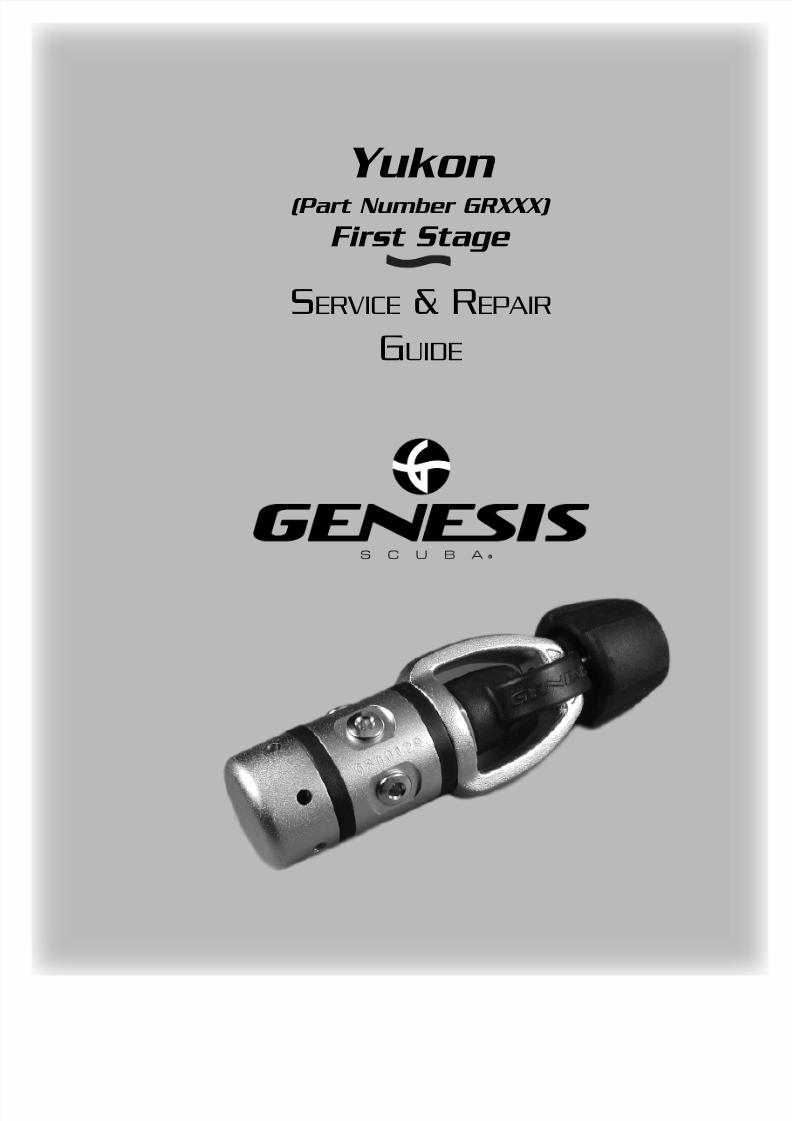
Yukon (Part Number GRXXX)
First Stage
S ERVICE & R EPAIR
G UIDE
8/6/2019 Yukon 1st Stage
http://slidepdf.com/reader/full/yukon-1st-stage 2/35
Contents Contents
ntroduction ............................................................................ 3
About This Manual .........................................................................3Scheduled Service ....................................................................................... 3
EAN/ Nitrox Service .................................................................................... 3
Use of Warnings, Cautions, & Notes ........................................................ 3
Function & Design ..........................................................................4
ection 1 – Facility Requirements ......................................... 5
Table 1 – Recommended Equipment and Suppliers ......................6
ection 2 - Preliminary Inspection ........................................ 7
External Inspection ....................................................................... 7
Immersion / Leak Test .....................................................................7
Intermediate Pressure Test ..........................................................8
ection 3 - Disassembly Procedures .................................... 9
General Guidelines ........................................................................9
ection 4 - Cleaning Procedures ........................................ 13Acidic Cleaning Procedure ......................................................... 13
EAN/Nitrox Cleaning Procedure ............................................... 16
ection 5 - Reassembly Procedures .................................... 26
ection 6 - Final Testing Procedures ................................. 30
Table 2 – Troubleshooting Guide ........................................ 32
chematic & Parts List (Compressed Air) ........................... 33
chematic & Parts List (EAN/ Nitrox) ................................. 35
8/6/2019 Yukon 1st Stage
http://slidepdf.com/reader/full/yukon-1st-stage 3/35
3 Copyright ©2001 Liberty
Service & Repair Manual
About This Manual
IntroductionIntroduction
As a service technician, you are entrusted with maintaining your customerequipment to the same standards with which it was manufactured. At Genesiare committed to providing you with the tools you will need to accomplish thimportant task, including the information provided in this manual.
Possession of this manual, however, does not constitute an offer by GenesScuba to sell component parts, nor does it qualify you to perform service or rfor Genesis Scuba products. In order to purchase spare parts or perform servand repair, you must be directly employed by an Authorized Genesis Dealer.
also your responsibility to obtain factory authorized training through your Genesis Scuba distribIf you are ever unsure about how to perform any of the procedures outlined in this manual,
please contact Genesis Scuba for technical assistance.
Scheduled Service
Regulators should be given the same care and maintenance as life support equipment. It istherefore important to perform scheduled overhaul service for the entire regulator (first and secstages) at least once every year with normal or infrequent use.
A unit that receives heavy or frequent use, however, should be serviced at least twice each yor more often - depending on the conditions of use and the manner in which it is maintained. (R
to the maintenance procedures outlined in the Genesis Regulator Owner’s Manual.).When performing service, whether it is a routine overhaul or a repair of a specific problem, important to understand how the regulator is designed and how it operates. An illustrated explation of the Yukon first stage design is provided on the following page.
EAN/ Nitrox Service
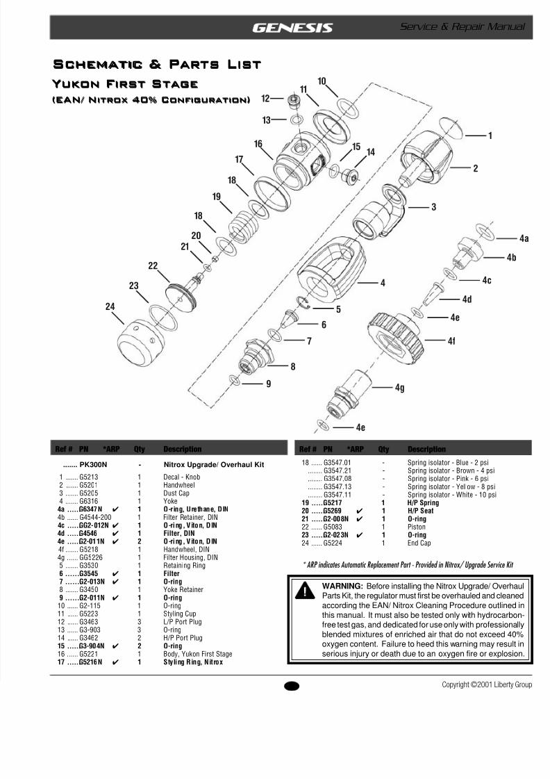
Genesis regulators can be upgraded for use with oxygen enriched air (EAN/ Nitrox) not toexceed 40% oxygen content. This upgrade must be performed in conjunction with a completeoverhaul, and includes a special cleaning procedure that is outlined in this manual.
Use of Warnings, Cautions, & Notes
About This Manual
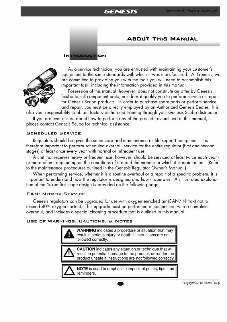
WARNING indicates a procedure or situation that mayresult in serious injury or death if instructions are notfollowed correctly.
CAUTION indicates any situation or technique that willresult in potential damage to the product, or render theproduct unsafe if instructions are not followed correctly.
NOTE is used to emphasize important points, tips, andreminders.
8/6/2019 Yukon 1st Stage
http://slidepdf.com/reader/full/yukon-1st-stage 4/35
4opyright ©2001 Liberty Group
Yukon First Stage
Function & Design
IntroductionIntroduction
Function & Design
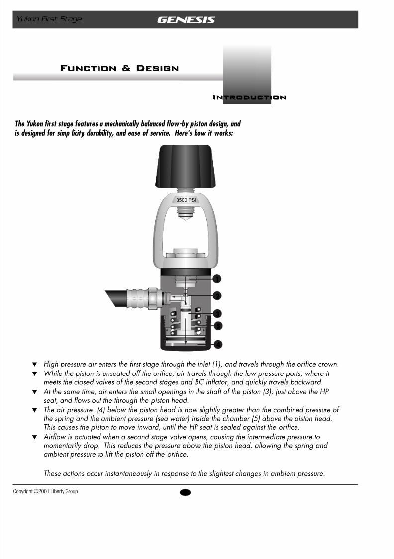
The Yukon first stage features a mechanically balanced flow-by piston design, and is designed for simp licity, durability, and ease of service. Here's how it works:
w High pressure air enters the first stage through the inlet (1), and travels through the orifice crown.w While the piston is unseated off the orifice, air travels through the low pressure ports, where it
meets the closed valves of the second stages and BC inflator, and quickly travels backward.w At the same time, air enters the small openings in the shaft of the piston (3), just above the HP
seat, and flows out the through the piston head.w The air pressure (4) below the piston head is now slightly greater than the combined pressure of
the spring and the ambient pressure (sea water) inside the chamber (5) above the piston head.This causes the piston to move inward, until the HP seat is sealed against the orifice.
w Airflow is actuated when a second stage valve opens, causing the intermediate pressure to momentarily drop. This reduces the pressure above the piston head, allowing the spring and ambient pressure to lift the piston off the orifice.
These actions occur instantaneously in response to the slightest changes in ambient pressure.
3500 PSI
1
2
3
4
5
8/6/2019 Yukon 1st Stage
http://slidepdf.com/reader/full/yukon-1st-stage 5/35
5 Copyright ©2001 Liberty
Service & Repair Manual
Facility Requirements
s e c t i o n
Facility Requirements
s e c t i o n
The service facility is perhaps the most important assetany professional dive store. It should be clean and welllighted, and stocked with a complete inventory of parts andmanufacturer's specialty tools for the products your store sAs a minimum requirement, your service facility should beequipped with the following items:t Ultrasonic Cleaner – Select the right size model that can
keep up with the volume of regulators that your store servicA built in timer and heater will help control the cleaning timand temperature of the solution, since most solutions work bwhen heated.
t Bench Mounted Vise – A vise is sometimes needed to hothe regulator secure – especially when removing the first st
yoke retainer. Special care must be taken, however, to avoidamage that can result from improper use of this tool. Be sto follow the instructions provided in this manual.
t Magnification Lamp – Strong lighting and magnificationessential requirements for performing a thorough parts insption - especially when locating the cause of a small leak.
t Quality Wrenches & Sockets – When working with braparts, it is especially critical to use the correct size wrench ato ensure that it fits properly over the part. The use of an adable wrench is very likely to cause damage to your customeregulator, and should be strictly avoided at all times.
t Calibrated Inch-Pound Torque Wrench – It is importafollow the manufacturer's torque values whenever they arespecified, in order to avoid overtightening or under-tightenipart. This is especially important for smaller parts and fitti
when overtightening can easily damage the part.t Calibrated Foot-Pound Torque Wrench – Torque
wrenches that can be set for both inch-pound and foot-pounmeasurements generally tend to be less accurate than wrencthat are designed to measure torque within a specific range.
t Genesis Specialty Tools – Specialty tools are criticallyimportant to performing each step of disassembly and reassbly according to factory prescribed procedures. Genesisspecialty tools that are required to perform service for the Yfirst stage are pictured on the following page.
1
8/6/2019 Yukon 1st Stage
http://slidepdf.com/reader/full/yukon-1st-stage 6/35
6opyright ©2001 Liberty Group
Yukon First Stage
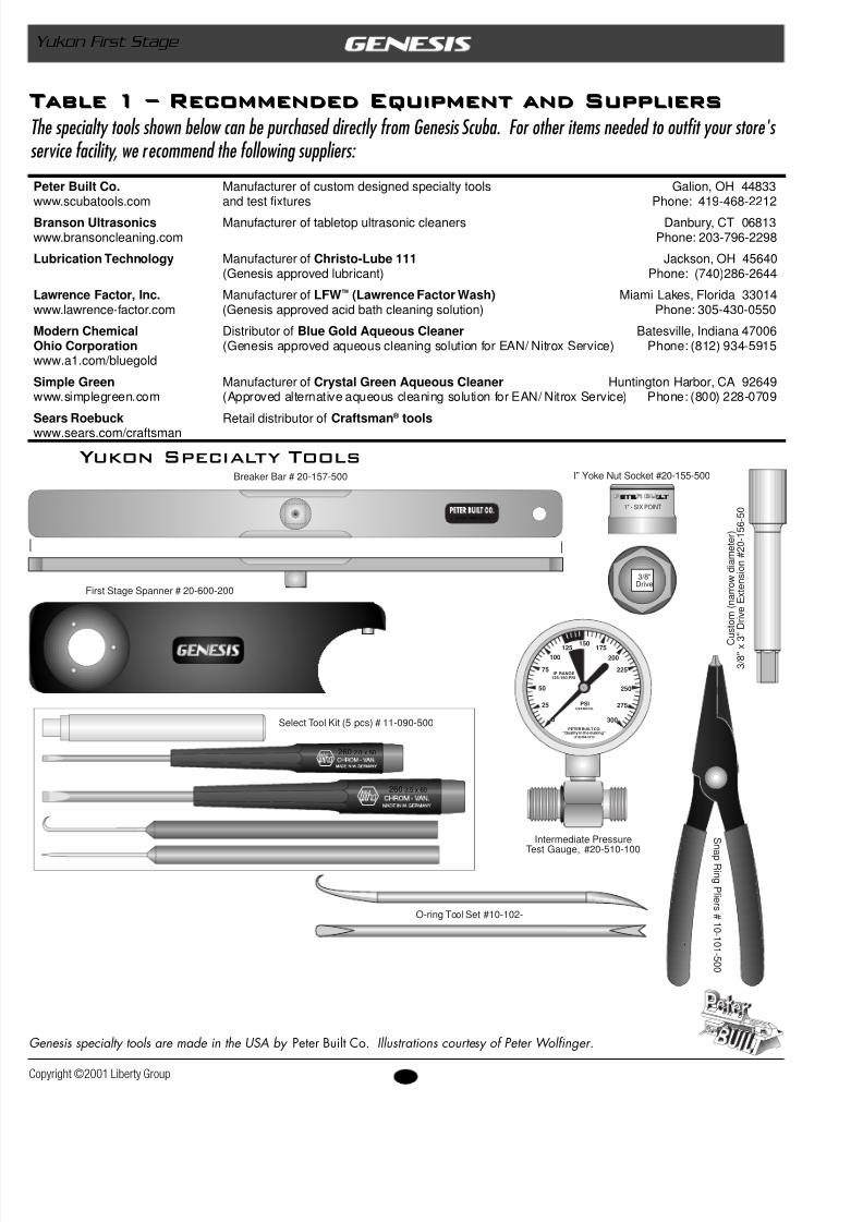
Table 1 – Recommended Equipment and SuppliersThe specialty tools shown below can be purchased directly from Genesis Scuba. For other iteservice facility, we recommend the following suppliers:
Table 1 – Recommended Equipment and Suppliers
Genesis specialty tools are made in the USA by Peter Built Co. Illustrations courtesy of Peter Wolfinger.
Peter Built Co. Manufacturer of custom designed specialty tools Galion, OH 44833www.scubatools.com and test fixtures Phone: 419-468-2212
Branson Ultrasonics Manufacturer of tabletop ultrasonic cleaners Danbury, CT 06813www.bransoncleaning.com Phone: 203-796-2298
Lubrication Technology Manufacturer of Christo-Lube 111 Jackson, OH 45640(Genesis approved lubricant) Phone: (740)286-2644
Lawrence Factor, Inc. Manufacturer of LFW ™ (Lawrence Factor Wash) Miami Lakes, Florida 33014www.lawrence-factor.com (Genesis approved acid bath cleaning solution) Phone: 305-430-0550
Modern Chemical Distributor of Blue Gold Aqueous Cleaner Batesville, Indiana 47006Ohio Corporation (Genesis approved aqueous cleaning solution for EAN/ Nitrox Service) Phone: (812) 934-5915www.a1.com/bluegold
Simple Green Manufacturer of Crystal Green Aqueous Cleaner Huntington Harbor, CA 92649www.simplegreen.com (Approved alternative aqueous cleaning solution for EAN/ Nitrox Service) Phone: (800) 228-0709
Sears Roebuck Retail distributor of Craftsman ® toolswww.sears.com/craftsman
Yukon Specialty Tools
(419) 468-2212
Breaker Bar # 20-157-500
First Stage Spanner # 20-600-200
P E T E R B U I LT
1" - SIX POINT
3/8"Drive
I” Yoke Nut Socket #20-155-500
C u s t o m
( n a r r o w
d i a m e
t e r )
3 / 8 " x
3 " D r i v e
E x t e n s i o n
# 2 0 - 1
5 6 - 5
0
100
200
80
60
40
20 180
160
120IP RANGE
125-150 PSI
PSI
PETER BUILT"Quality in the making"
(419)468-2212
USE NOOIL
140
25
50
150125
100
75
175
200
225
250
275
3000
IP RANGE125-150 PSI
PSIUSE NOOIL
PETER BUILT CO."Quality in the making"
(419)468-2212
260 3.5 x 60
260 2.0 x 50
Select Tool Kit (5 pcs) # 11-090-500
Intermediate PressureTest Gauge, #20-510-100
S n
a pR i n
gP l i er s
# 1
0 -1
0 1 - 5
0 0
O-ring Tool Set #10-102-
8/6/2019 Yukon 1st Stage
http://slidepdf.com/reader/full/yukon-1st-stage 7/35
7 Copyright ©2001 Liberty
Service & Repair Manual
Preliminary InspectionPreliminary Inspection
s e c t i o n
2s e c t i o n
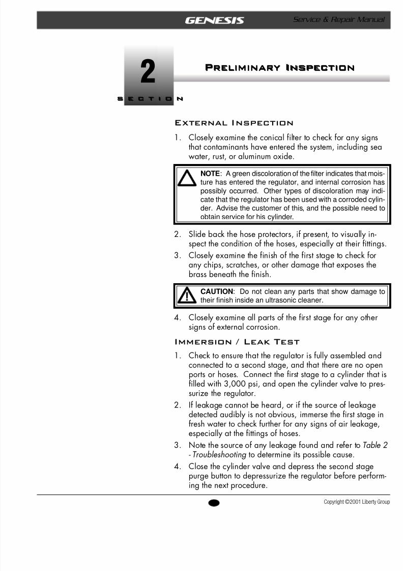
External Inspection
1. Closely examine the conical filter to check for any signthat contaminants have entered the system, including swater, rust, or aluminum oxide.
NOTE : A green discoloration of the filter indicates that mois-ture has entered the regulator, and internal corrosion haspossibly occurred. Other types of discoloration may indi-
cate that the regulator has been used with a corroded cylin-der. Advise the customer of this, and the possible need toobtain service for his cylinder.
2. Slide back the hose protectors, if present, to visually inspect the condition of the hoses, especially at their fitti
3. Closely examine the finish of the first stage to check foany chips, scratches, or other damage that exposes thebrass beneath the finish.
CAUTION : Do not clean any parts that show damage to
their finish inside an ultrasonic cleaner.
4. Closely examine all parts of the first stage for any othesigns of external corrosion.
Immersion / Leak Test
1. Check to ensure that the regulator is fully assembled aconnected to a second stage, and that there are no openports or hoses. Connect the first stage to a cylinder thfilled with 3,000 psi, and open the cylinder valve to prsurize the regulator.
2. If leakage cannot be heard, or if the source of leakagedetected audibly is not obvious, immerse the first stagfresh water to check further for any signs of air leakagespecially at the fittings of hoses.
3. Note the source of any leakage found and refer to Tabl- Troubleshootingto determine its possible cause.
4. Close the cylinder valve and depress the second stagepurge button to depressurize the regulator before perfoing the next procedure.
8/6/2019 Yukon 1st Stage
http://slidepdf.com/reader/full/yukon-1st-stage 8/35
8opyright ©2001 Liberty Group
Yukon First Stage
ntermediate Pressure Test
NOTE: It is not necessary to perform this test unless a prob-lem has been reported that requires diagnostic troubleshoot-ing and repair. When performing routine overhaul service,proceed directly to the following section, Disassembly .
1. Connect a calibrated intermediate pressure test gauge tothe regulator, either with a quick-disconnect inflator hose orwith the female fitting of a second stage LP hose, depend-ing on the connection of the test gauge.
CAUTION : To provide a safety relief valve in the event thatintermediate pressure exceeds 155-170 psi, ensure that afully assembled and properly adjusted second stage is con-nected to the first stage before pressurizing. Failure to re-lieve intermediate pressure that exceeds 400 psi may result
in damage or rupture of the test gauge or LP hose, andcould cause serious personal injury.
2. Slowly open the supply valve to pressurize the first stage.Closely monitor the IP test gauge to determine whether theintermediate pressure rises above 145 psi.
3. Note the intermediate pressure indicated by the testgauge, and purge the second stage several times to deter-mine whether lockup is achieved without creeping orfluctuating back and forth.
4. If the intermediate pressure creeps up or otherwise fluctu-ates after cycling the regulator, wait for it to stabilize (ifpossible) before making a final note of the intermediatepressure.
NOTE : Correct intermediate pressure for the Yukon firststage is 140 ( ± 5) psi, with an inlet pressure between 2,500- 3,000 psi.
5. Close the supply valve and depress the second stagepurge button to depressurize the system before attempting
to perform any disassembly.
w After completing the Preliminary Inspection, proceed to Section 3 – Disassembly
8/6/2019 Yukon 1st Stage
http://slidepdf.com/reader/full/yukon-1st-stage 9/35
9 Copyright ©2001 Liberty
Service & Repair Manual
Disassembly Procedures
s e c t i o n
3s e c t i o n
Disassembly Procedures
General Guidelines
w Prior to performing any disassembly, check to ensure tthe service facility is well equipped with all the tools aparts needed to perform a complete service from start finish. DO NOT attempt to perform the service unlessthe required tools and parts are available.
w All o-rings are classified as being either dynamic or staDynamic o-rings are those which sustain friction andmovement, as they are either mounted directly onto amoving part, or create a seal against a moving part.Static o-rings simply create a seal between two non- moving parts, and are therefore less subject to wear thdynamic o-rings. After passing close inspection, statiO-rings may sometimes be reused, although this is notnecessarily recommended. Dynamic O-rings must be
automatically discarded and replaced with every servicregardless of age or appearance.w Refer to the schematic and parts list while performing
procedures. Each part is identified by its reference nushown on the drawing the first time it is referred to in procedure.
w Do not attempt to reuse parts that are designated to beautomatically discarded and replaced with the partsprovided in the overhaul parts kit. These parts shouldshown to the customer, however, to ensure their confi
dence and satisfaction that complete overhaul servicebeen performed.w Inspect all reusable parts as directed, either during or
immediately following the disassembly procedures. Win doubt, compare the part with one that is new to besdetermine its condition.
8/6/2019 Yukon 1st Stage
http://slidepdf.com/reader/full/yukon-1st-stage 10/35
10opyright ©2001 Liberty Group
Yukon First Stage
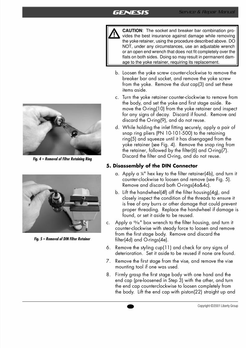
Fig. 3 – Removal of yoke retainer
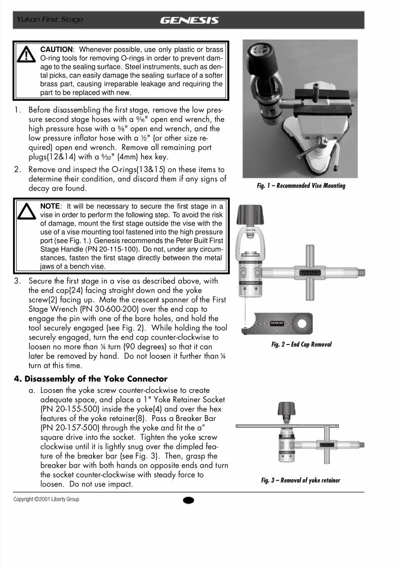
Fig. 1 – Recommended Vise Mounting
Fig. 2 – End Cap Removal
CAUTION : Whenever possible, use only plastic or brassO-ring tools for removing O-rings in order to prevent dam-age to the sealing surface. Steel instruments, such as den-tal picks, can easily damage the sealing surface of a softerbrass part, causing irreparable leakage and requiring thepart to be replaced with new.
1. Before disassembling the first stage, remove the low pres-sure second stage hoses with a b " open end wrench, thehigh pressure hose with a s " open end wrench, and thelow pressure inflator hose with a2 " (or other size re-quired) open end wrench. Remove all remaining portplugs(12&14) with a® " (4mm) hex key.
2. Remove and inspect the O-rings(13&15) on these items todetermine their condition, and discard them if any signs ofdecay are found.
NOTE : It will be necessary to secure the first stage in avise in order to perform the following step. To avoid the riskof damage, mount the first stage outside the vise with theuse of a vise mounting tool fastened into the high pressureport (see Fig. 1.) Genesis recommends the Peter Built FirstStage Handle (PN 20-115-100). Do not, under any circum-stances, fasten the first stage directly between the metal
jaws of a bench vise.
3. Secure the first stage in a vise as described above, withthe end cap(24) facing straight down and the yokescrew(2) facing up. Mate the crescent spanner of the FirstStage Wrench (PN 30-600-200) over the end cap toengage the pin with one of the bore holes, and hold thetool securely engaged (see Fig. 2). While holding the toolsecurely engaged, turn the end cap counter-clockwise toloosen no more than 4 turn (90 degrees) so that it canlater be removed by hand. Do not loosen it further than4
turn at this time.4. Disassembly of the Yoke Connector
a. Loosen the yoke screw counter-clockwise to createadequate space, and place a 1" Yoke Retainer Socket(PN 20-155-500) inside the yoke(4) and over the hexfeatures of the yoke retainer(8). Pass a Breaker Bar(PN 20-157-500) through the yoke and fit the a”square drive into the socket. Tighten the yoke screwclockwise until it is lightly snug over the dimpled fea-ture of the breaker bar (see Fig. 3). Then, grasp thebreaker bar with both hands on opposite ends and turnthe socket counter-clockwise with steady force toloosen. Do not use impact.
PETER BUILT(419) 468-2212
3500 PSI
www.genesisscuba.com
PETER BE T E R B U I L T
1"-SIX POINT
PETER BUILT(419)468-2212
8/6/2019 Yukon 1st Stage
http://slidepdf.com/reader/full/yukon-1st-stage 11/35
11 Copyright ©2001 Liberty
Service & Repair Manual
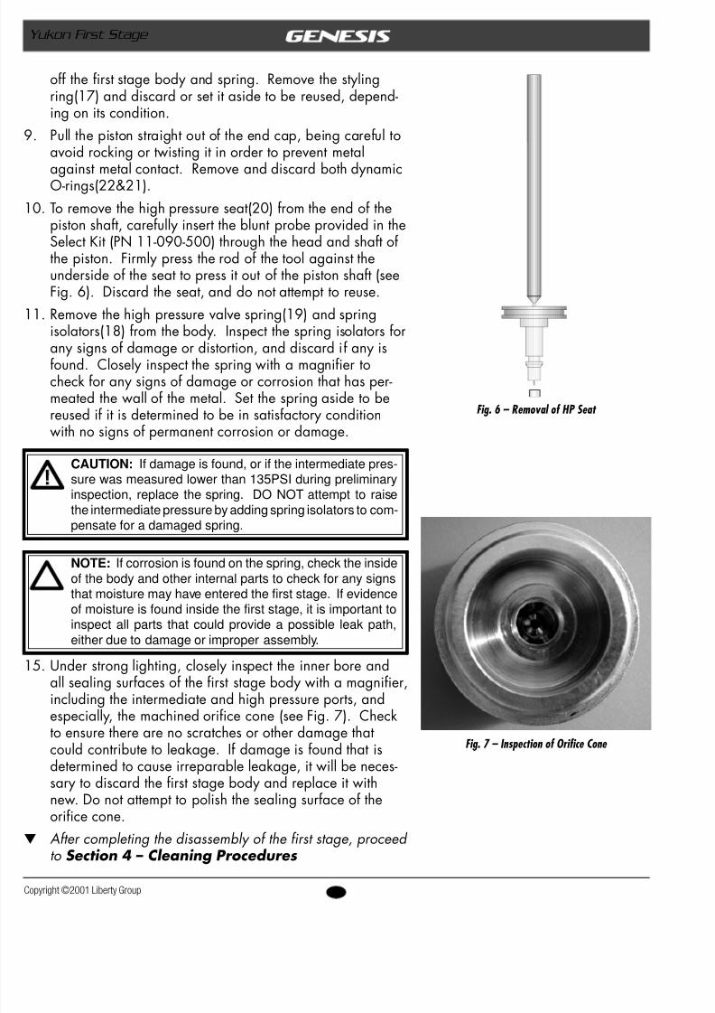
Fig. 4 – Removal of Filter Retaining Ring
Fig. 5 – Removal of DIN Filter Retainer
CAUTION : The socket and breaker bar combination pro-vides the best insurance against damage while removingthe yoke retainer, using the procedure described above. DONOT, under any circumstances, use an adjustable wrenchor an open end wrench that does not fit completely over theflats on both sides. Doing so may result in permanent dam-age to the yoke retainer, requiring its replacement.
b. Loosen the yoke screw counter-clockwise to removbreaker bar and socket, and remove the yoke screwfrom the yoke. Remove the dust cap(3) and set theitems aside.
c. Turn the yoke retainer counter-clockwise to removthe body, and set the yoke and first stage aside. Remove the O-ring(10) from the yoke retainer and insfor any signs of decay. Discard if found. Remove
discard the O-ring(9), and do not reuse.d. While holding the inlet fitting securely, apply a paisnap ring pliers (PN 10-101-500) to the retainingring(5) and squeeze until it has disengaged from th
yoke retainer (see Fig. 4). Remove the snap ring frthe retainer, followed by the filter(6) and O-ring(7)Discard the filter and O-ring, and do not reuse.
5. Disassembly of the DIN Connectora. Apply a 4 " hex key to the filter retainer(4b), and tu
counter-clockwise to loosen and remove (see Fig. 5Remove and discard both O-rings(4a&4c).
b. Lift the handwheel(4f) off the filter housing(4g), anclosely inspect the condition of the threads to ensuris free of any burrs or other damage that could prevproper threading. Replace the handwheel if damagfound, or set it aside to be reused.
c. Apply a m " box wrench to the filter housing, and turncounter-clockwise with steady force to loosen and remfrom the first stage body. Remove and discard thefilter(4d) and O-rings(4e).
6. Remove the styling cup(11) and check for any signs ofdeterioration. Set it aside to be reused if none are foun
7. Remove the first stage from the vise, and remove the vmounting tool if one was used.
8. Firmly grasp the first stage body with one hand and thend cap (pre-loosened in Step 3) with the other, and tuthe end cap counterclockwise to loosen completely frothe body. Lift the end cap with piston(22) straight up
8/6/2019 Yukon 1st Stage
http://slidepdf.com/reader/full/yukon-1st-stage 12/35
12opyright ©2001 Liberty Group
Yukon First Stage
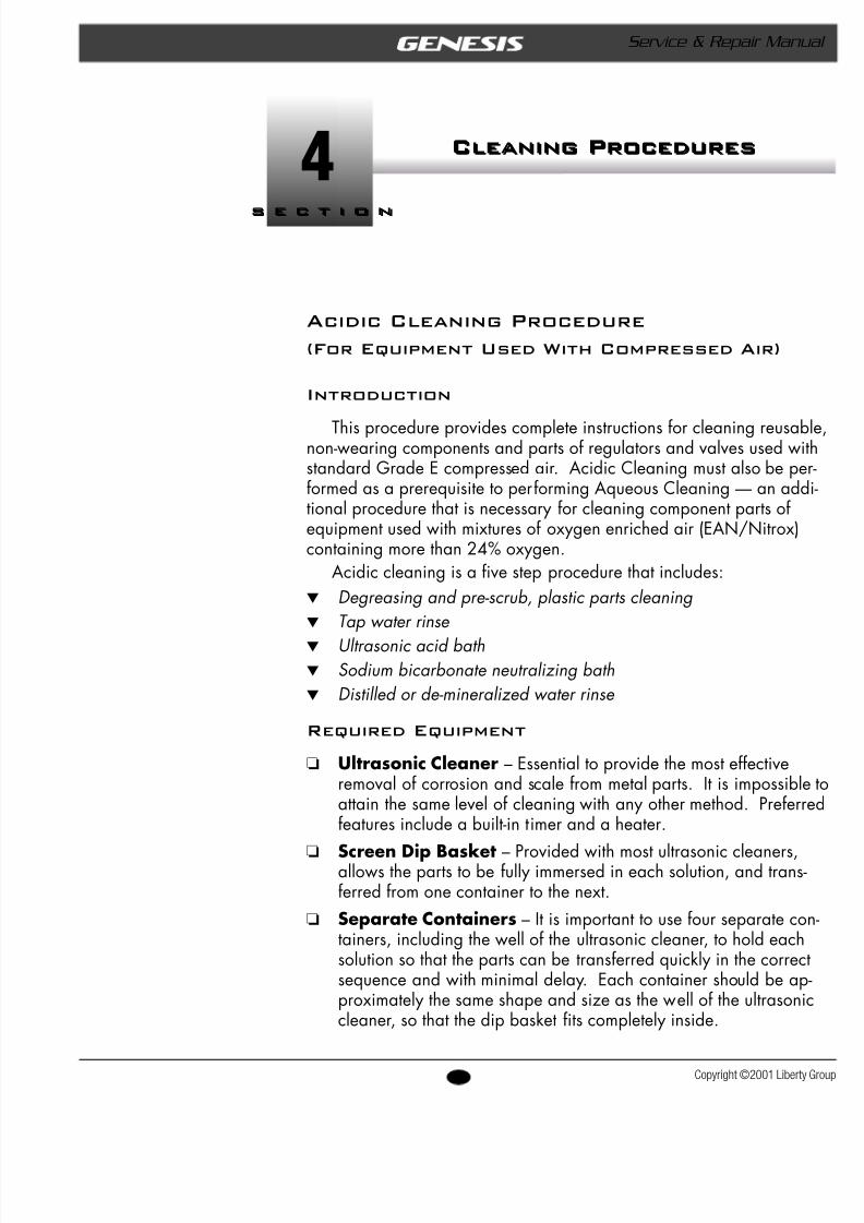
Fig. 6 – Removal of HP Seat
off the first stage body and spring. Remove the stylingring(17) and discard or set it aside to be reused, depend-ing on its condition.
9. Pull the piston straight out of the end cap, being careful toavoid rocking or twisting it in order to prevent metalagainst metal contact. Remove and discard both dynamicO-rings(22&21).
10. To remove the high pressure seat(20) from the end of thepiston shaft, carefully insert the blunt probe provided in theSelect Kit (PN 11-090-500) through the head and shaft ofthe piston. Firmly press the rod of the tool against theunderside of the seat to press it out of the piston shaft (seeFig. 6). Discard the seat, and do not attempt to reuse.
11. Remove the high pressure valve spring(19) and springisolators(18) from the body. Inspect the spring isolators for
any signs of damage or distortion, and discard if any isfound. Closely inspect the spring with a magnifier tocheck for any signs of damage or corrosion that has per-meated the wall of the metal. Set the spring aside to bereused if it is determined to be in satisfactory conditionwith no signs of permanent corrosion or damage.
CAUTION: If damage is found, or if the intermediate pres-sure was measured lower than 135PSI during preliminaryinspection, replace the spring. DO NOT attempt to raisethe intermediate pressure by adding spring isolators to com-pensate for a damaged spring.
NOTE: If corrosion is found on the spring, check the insideof the body and other internal parts to check for any signsthat moisture may have entered the first stage. If evidenceof moisture is found inside the first stage, it is important toinspect all parts that could provide a possible leak path,either due to damage or improper assembly.
15. Under strong lighting, closely inspect the inner bore andall sealing surfaces of the first stage body with a magnifier,including the intermediate and high pressure ports, andespecially, the machined orifice cone (see Fig. 7). Checkto ensure there are no scratches or other damage thatcould contribute to leakage. If damage is found that isdetermined to cause irreparable leakage, it will be neces-sary to discard the first stage body and replace it withnew. Do not attempt to polish the sealing surface of theorifice cone.
w After completing the disassembly of the first stage, proceed to Section 4 – Cleaning Procedures
Fig. 7 – Inspection of Orifice Cone
8/6/2019 Yukon 1st Stage
http://slidepdf.com/reader/full/yukon-1st-stage 13/35
13 Copyright ©2001 Liberty
Service & Repair Manual
Cleaning ProceduresCleaning Procedures
s e c t i o n
4s e c t i o n
Acidic Cleaning Procedure
(For Equipment Used With Compressed Air)
Introduction
This procedure provides complete instructions for cleaning reusanon-wearing components and parts of regulators and valves used wistandard Grade E compressed air. Acidic Cleaning must also be peformed as a prerequisite to performing Aqueous Cleaning — an addtional procedure that is necessary for cleaning component parts ofequipment used with mixtures of oxygen enriched air (EAN/Nitroxcontaining more than 24% oxygen.
Acidic cleaning is a five step procedure that includes:w Degreasing and pre-scrub, plastic parts cleaningw Tap water rinse w Ultrasonic acid bathw Sodium bicarbonate neutralizing bathw Distilled or de-mineralized water rinse
Required Equipment
t Ultrasonic Cleaner – Essential to provide the most effectiveremoval of corrosion and scale from metal parts. It is impossibattain the same level of cleaning with any other method. Preferfeatures include a built-in timer and a heater.
t Screen Dip Basket – Provided with most ultrasonic cleaners,allows the parts to be fully immersed in each solution, and transferred from one container to the next.
t Separate Containers – It is important to use four separate cotainers, including the well of the ultrasonic cleaner, to hold eachsolution so that the parts can be transferred quickly in the corresequence and with minimal delay. Each container should be approximately the same shape and size as the well of the ultrasoncleaner, so that the dip basket fits completely inside.
8/6/2019 Yukon 1st Stage
http://slidepdf.com/reader/full/yukon-1st-stage 14/35
14opyright ©2001 Liberty Group
Yukon First Stage
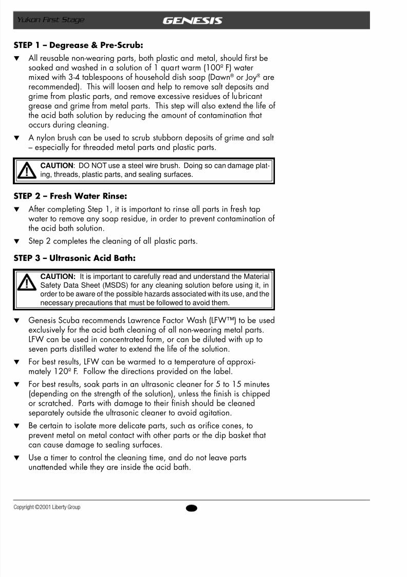
STEP 1 – Degrease & Pre-Scrub:All reusable non-wearing parts, both plastic and metal, should first besoaked and washed in a solution of 1 quart warm (100º F) watermixed with 3-4 tablespoons of household dish soap (Dawn® or Joy® arerecommended). This will loosen and help to remove salt deposits andgrime from plastic parts, and remove excessive residues of lubricantgrease and grime from metal parts. This step will also extend the life ofthe acid bath solution by reducing the amount of contamination thatoccurs during cleaning.A nylon brush can be used to scrub stubborn deposits of grime and salt– especially for threaded metal parts and plastic parts.
CAUTION : DO NOT use a steel wire brush. Doing so can damage plat-ing, threads, plastic parts, and sealing surfaces.
STEP 2 – Fresh Water Rinse:After completing Step 1, it is important to rinse all parts in fresh tapwater to remove any soap residue, in order to prevent contamination ofthe acid bath solution.Step 2 completes the cleaning of all plastic parts.
STEP 3 – Ultrasonic Acid Bath:
CAUTION: It is important to carefully read and understand the MaterialSafety Data Sheet (MSDS) for any cleaning solution before using it, inorder to be aware of the possible hazards associated with its use, and the
necessary precautions that must be followed to avoid them.
Genesis Scuba recommends Lawrence Factor Wash (LFW™) to be usedexclusively for the acid bath cleaning of all non-wearing metal parts.LFW can be used in concentrated form, or can be diluted with up toseven parts distilled water to extend the life of the solution.For best results, LFW can be warmed to a temperature of approxi-mately 120º F. Follow the directions provided on the label.For best results, soak parts in an ultrasonic cleaner for 5 to 15 minutes(depending on the strength of the solution), unless the finish is chipped
or scratched. Parts with damage to their finish should be cleanedseparately outside the ultrasonic cleaner to avoid agitation.Be certain to isolate more delicate parts, such as orifice cones, toprevent metal on metal contact with other parts or the dip basket thatcan cause damage to sealing surfaces.Use a timer to control the cleaning time, and do not leave partsunattended while they are inside the acid bath.
8/6/2019 Yukon 1st Stage
http://slidepdf.com/reader/full/yukon-1st-stage 15/35
15 Copyright ©2001 Liberty
Service & Repair Manual
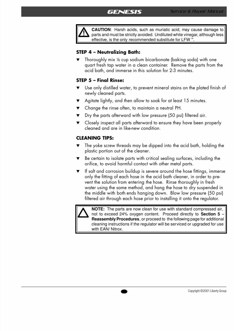
CAUTION : Harsh acids, such as muriatic acid, may cause damage toparts and must be strictly avoided. Undiluted white vinegar, although lesseffective, is the only recommended substitute for LFW ™.
STEP 4 – Neutralizing Bath:w Thoroughly mix8 cup sodium bicarbonate (baking soda) with one
quart fresh tap water in a clean container. Remove the parts from acid bath, and immerse in this solution for 2-3 minutes.
STEP 5 – Final Rinse:w Use only distilled water, to prevent mineral stains on the plated fin
newly cleaned parts.w Agitate lightly, and then allow to soak for at least 15 minutes.w Change the rinse often, to maintain a neutral PH.
w Dry the parts afterward with low pressure (50 psi) filtered air.w Closely inspect all parts afterward to ensure they have been proper
cleaned and are in like-new condition.
CLEANING TIPS:w The yoke screw threads may be dipped into the acid bath, holding
plastic portion out of the cleaner.w Be certain to isolate parts with critical sealing surfaces, including t
orifice, to avoid harmful contact with other metal parts.w If salt and corrosion buildup is severe around the hose fittings, imm
only the fitting of each hose in the acid bath cleaner, in order to prevent the solution from entering the hose. Rinse thoroughly in freshwater using the same method, and hang the hose to dry suspended the middle with both ends hanging down. Blow low pressure (50 pfiltered air through each hose prior to installing it onto the regulato
NOTE: The parts are now clean for use with standard compressed air,not to exceed 24% oxygen content. Proceed directly to Section 5Reassembly Procedures , or proceed to the following page for additionalcleaning instructions if the regulator will be serviced or upgraded for usewith EAN/ Nitrox.
8/6/2019 Yukon 1st Stage
http://slidepdf.com/reader/full/yukon-1st-stage 16/35
16opyright ©2001 Liberty Group
Yukon First Stage
EAN/Nitrox Cleaning Procedure
For Equipment Used With Oxygen Enriched Air)
ntroduction
Genesis Scuba regulators may be upgraded for dedicated use withmixtures of oxygen enriched air (EAN/Nitrox), not exceeding 40% oxygen.This upgrade must only be performed by an Authorized Genesis Dealer,and requires the installation of the first stage Nitrox overhaul/ upgradeparts kit that is provided specifically for each model first stage regulatorrefer to the schematic parts list).
Genesis Nitrox upgrade/overhaul parts kits contain O-rings, seats, andwashers made of materials that are proven compatible with oxygen en-iched air, up to 40% oxygen. It is very important to replace all standardeplacement parts with those provided in each kit, and not to reuse any ofhem or replace parts individually under any circumstances.
The parts contained in each kit have been specially cleaned and pack-aged to ensure the absence of contaminants, and must be handled accord-ng to the instructions provided in this procedure to avoid accidental con-amination.
NOTE : It is important to handle the contents of the Nitrox upgrade partskits with care, wearing rubber or plastic gloves to prevent contaminationwith skin oil. In the event that contamination occurs, the parts must becleaned according to the procedure outlined below.
Prior to the installation of a Nitrox upgrade/ overhaul parts kit, theegulator must undergo a complete overhaul service that includes special
cleaning and parts inspection according to the steps outlined in this proce-dure. Special cleaning is necessary to remove contaminants from theegulator that may react with oxygen enriched air.
Standard compressed air usually contains a certain level of hydrocar-bons, including invisible traces of compressor oil, that are not consideredharmful or dangerous when kept within the acceptable limits for Grade Ecompressed air. When these same levels of hydrocarbons come in contactwith oxygen enriched compressed air, however, they can pose a very realhazard that can lead to an oxygen fire or explosion. For this reason, it is
mportant to clean the individual parts and components of any regulator orvalve before it can be used with enriched air, in order to remove all tracesof hydrocarbon contamination.
Although acidic cleaning is very effective for removing corrosion andscale, it is not sufficient by itself to remove certain sources of contamination.t is therefore necessary to perform an additional cleaning procedure that is
specifically formulated to remove all traces of silicone grease, skin oil,compressor oil residue, and other hydrocarbon contamination.
8/6/2019 Yukon 1st Stage
http://slidepdf.com/reader/full/yukon-1st-stage 17/35
17 Copyright ©2001 Liberty
Service & Repair Manual
EAN/Nitrox Cleaning is a four step procedure that includes:w Pre-Cleaning with Ultrasonic Acid Bathw Ultrasonic Aqueous Cleaning Bathw Distilled or De-mineralized Water Rinse w Final Inspection (direct light, ultraviolet, and wipe test)
NOTE: Although second stage components are not usually exposed tohigh pressure oxygen enriched air, Genesis Scuba recommends that thesame cleaning and assembly procedures be followed for the completeregulator. This prevents the possibility of cross contamination, and guar-antees the integrity of the complete system.
REQUIRED EQUIPMENT:
t Dedicated Ultrasonic Cleaner – To avoid contamination, it isimportant to use a separate cleaner that is kept dedicated for aqueo
cleaning, in addition to one used for acidic cleaning. Preferred features include a built-in timer and a heater.t Screen Dip Basket – Provided with most ultrasonic cleaners, all
the parts to be fully immersed in each solution, and transferred fromone container to the next.
t Powderless Latex Gloves – Skin oil is another source of potencontamination that can react with oxygen enriched air. Once the phave been cleaned, gloves must be worn at all times to prevent themfrom becoming contaminated during handling.
t Dedicated Rinse Tub – To avoid recontamination, it is important
use a separate rinse tub that is kept clean and dedicated for aqueoucleaning, in addition to the rinse tub that is used for acidic cleaningt Incandescent or Fluorescent Lighting – Required during final
inspection to detect more obvious signs of contamination.t Ultraviolet Lighting – Required during final inspection to detect
contamination that is not visible beneath normal lighting.t Lint Free Cotton Wipes – Required for cleaning and inspection.
Preparing the Workstation
Enriched air cleaning procedures may be carried out in the same wo
area that is used for servicing air scuba equipment, provided that it is kreasonably clean, and airborne pollutants (dust, soot, etc.) are not visibpresent on surrounding surfaces. Ventilation ducts and windows shoulchecked to ensure that airflow will not introduce these contaminants wcleaning and service is in process.w To ensure cleanliness, the work surface should be covered with a c
sheet of butcher paper or plastic sheeting.w The technician must wear clean, non-powdered latex or plastic glo
whenever handling cleaned parts (including upgrade parts kit), in oto prevent contamination with skin oil.
8/6/2019 Yukon 1st Stage
http://slidepdf.com/reader/full/yukon-1st-stage 18/35
18opyright ©2001 Liberty Group
Yukon First Stage
NOTE: All tools and fixtures, including the ultrasonic cleaner well, mustbe kept completely clean of any contaminants. For this reason, a sepa-rate set of clean tools should be used for the reassembly of enriched airequipment, different from those used for normal air equipment.
ACIDIC PRE-CLEANING –Before performing aqueous cleaning, partsmust first be cleaned with the acidic cleaning procedure outlined on page15 to ensure the complete removal of any corrosion or scale. Final drying,however, is not necessary.
NOTE : Use only LFW™ cleaning solution, which contains an additionaldegreasing agent. White vinegar is not an acceptable cleaning agent forEAN/ Nitrox pre-cleaning.
ULTRASONIC AQUEOUS BATH
CAUTION: It is important to carefully read and understand the MaterialSafety Data Sheet (MSDS) for any cleaning solution before using it, inorder to understand the possible hazards associated with its use, and thenecessary precautions that must be followed to avoid them.
General Guidelines
It is important to select an aqueous cleaning solution that is non-carcino-genic, non-toxic, and biodegradable, so that it can be safely disposedof by emptying it into a sewer system that is connected to a wastetreatment facility. It must also be non-damaging to the materials of soft
wearing parts, including seats, O-rings, washers, and gaskets. Last, itmust be easily rinsed away so that it leaves no residue. Refer to Table1 on Page 4, which lists the aqueous cleaning solution that GenesisScuba has currently approved.The aqueous cleaning solution must be diluted only with distilled water,according to the ratio specified by the manufacturer.It is important to pre-heat the aqueous cleaning solution toapproximately 130º F.The aqueous cleaning solution can be reused at least once, but willeventually require replacement as more contaminants and particulatematter are held in suspension. Frequently examine the appearance ofthe previously used solution in a clear beaker, and compare it along-side another beaker containing fresh solution in good lighting (dilutedwith the same ratio of demineralized water). When the appearancebegins to vary between fresh and used, or when contaminants can bevisually detected, the solution should be disposed of and replaced withnew. Whenever in doubt, dispose of the solution and replace withfresh.
8/6/2019 Yukon 1st Stage
http://slidepdf.com/reader/full/yukon-1st-stage 19/35
19 Copyright ©2001 Liberty
Service & Repair Manual
1. Place the parts inside a clean dip basket and lower the basket into ttank of a separate ultrasonic cleaner which contains an approvedaqueous cleaning solution. (Refer to Table 1 for an approved andrecommended solution, and follow the manufacturer’s instructionsdilution rates and recommended working temperatures.) Be certaiisolate more delicate parts, such as orifice cones, to prevent metal metal contact with other parts or the dip basket that can cause damto sealing surfaces.
2. Before removing the parts, it is important to don clean powderless gloves in order to prevent any subsequent contamination with skin Avoid touching the external surface of the gloves with bare fingersthe process of donning. Without this barrier present, parts will beccontaminated with skin oil.
NOTE: It is important to avoid handling clean parts with bare hands whileperforming the rinsing, inspection, and reassembly procedures. Doing so
will re-contaminate the parts with skin oil, and require them to be cleanedagain prior to reassembly.
3. With a small, nylon brush and lint-free swabs, scrub all surfaces ofeach part, and allow to soak for an additional 5-10 minutes beforeremoving from the ultrasonic cleaner. Certain parts with complexfeatures may require more attention - especially those which contaclosed recesses and chambers. It is important to ensure that these thoroughly flushed with solution, and that contaminant residue is ntrapped inside.
Demineralized or Distilled Water Rinse:NOTE: Tap water drawn from the faucet often contains high levels ofminerals, and is considered unsuitable for use with aqueous cleaning,either as a diluent or final rinse. Inexpensive filtration systems may beused which easily filter out most minerals, rendering the water “deminer-alized.” For high volume operations, this is a less expensive alternative tobottled distilled water.
1. When immersion in the aqueous cleaner has been completed, it isextremely important to transfer all parts into a clean container fillewith fresh distilled or demineralized water that is heated to approxmately 140˚ F, to facilitate faster drying. Rinse each part thoroughwith mild agitation to ensure thorough rinsing and the complete re-moval of cleaning solution. Parts with more complex features will quire additional attention to ensure complete rinsing of threads, creices, and recesses.
2. Dry immediately afterward, using only low pressure (50 psi), hydrbon-free gas (Nitrogen or EAN).
3. When drying is completed, set the parts aside on a clean, lint-freesurface covered with butcher paper or cellophane.
8/6/2019 Yukon 1st Stage
http://slidepdf.com/reader/full/yukon-1st-stage 20/35
20opyright ©2001 Liberty Group
Yukon First Stage
Final Inspection:When each part has been completely cleaned and dried, it must be
closely inspected to ensure the total absence of contamination or cleanerresidue. In the event that contamination is still found during inspection, itmay be necessary to re-clean the part. Inspection is a critical procedurethat must be performed in three consecutive steps.1. Gently wipe all surfaces of each part with a clean, lint-free wipe, and
closely inspect both the wipe and part under strong fluorescent orincandescent light to check for any signs of scale, corrosion, damagedplating, burrs, filings, grease, fingerprints, oil, or other contamination.If contamination if found, repeat the above cleaning procedure orreplace the part as needed.
2. Assuming no contamination is found, immediately inspect the samepart and wipe under ultraviolet light to check for any signs of oils,grease, or fine particulate matter which will fluoresce (glow) if present.If found, repeat the aqueous cleaning procedure.
NOTE: Isolated particles of dust may be eliminated with low pressure,hydrocarbon-free gas.
3. Wrap or cover all metal parts with cellophane or other plastic untilready to begin reassembly.
NOTE: Before proceeding, clean fingertips of latex gloves with isopropylalcohol to remove any contamination.
4. Examine each replacement parts kit to determine that it has not beenpreviously opened, and that the individual parts have not been ex-posed to possible contamination, including handling with bare fingers.
WARNING: Do not attempt to use individually ordered spare parts as asubstitute for those packaged in kit form directly from Genesis Scuba.Doing so will render the product incompatible for use with enriched air,and may seriously jeopardize the safety of the diver.
5. Closely inspect all new replacement parts for both the first and secondstage, including O-rings, seats, filters, and gaskets, under fluorescentand ultraviolet light as prescribed above. Examine the condition of theO-rings to ensure they are in new condition, and do not show anysigns of decay. If contamination is found, it will be necessary to re-clean the parts, following the procedures outlined above.
8/6/2019 Yukon 1st Stage
http://slidepdf.com/reader/full/yukon-1st-stage 21/35
21 Copyright ©2001 Liberty
Service & Repair Manual
LOW PRESSURE HOSE ASSEMBLIES1. Ultrasonically clean both hose fittings by dipping only the hose end
the LFW™ acid bath, and rinse thoroughly in distilled water.2. Inspect each fitting to ensure that all scale and corrosion is remove
and re-clean if necessary, using a small nylon brush.
3. Run aqueous cleaning solution through the hose in both directions,checking to ensure that no foreign matter or loose material exits thhose when it is drained. If evidence of internal decay is visible, dicard the hose and replace with new.
4. Don clean, powderless latex gloves in order to prevent any subsequcontamination with skin oils. Avoid touching the external surface gloves with bare fingers in the process of donning. If contaminatioa glove does occur, it can be cleaned with isopropyl alcohol.
5. Ultrasonically clean both fittings inside and out with aqueous cleansolution, using a soft nylon brush and lint-free swabs to clean all sufaces, including threads, crevices, and recesses.
6. Thoroughly rinse the hose inside and out with heated, demineralizewater, to completely remove all traces of aqueous cleaning solution
7. Direct hydrocarbon-free gas through the hose until it is completelyinside and out.
8. Inspect the hose according to the inspection procedure outlined in tinstructions.
9. Set the hose aside on clean surface, and wrap both fittings with celphane until it is ready for reassembly onto first and second stages.
HIGH PRESSURE HOSE ASSEMBLY1. While holding the retaining nut secure at the base of the submersib
pressure gauge module with a b ” open end wrench, apply a separab ” open end wrench to turn the hose fitting below it counter-clockto loosen and remove the hose.
CAUTION: Do not attempt to loosen the hose fitting without holding theretaining jam nut secure, or otherwise attempt to remove the nut. Doingso may result in irreparable damage to the pressure gauge, causing it toflood, and will render its warranty null and void.
2. Carefully remove the high pressure airspool from inside either the hose fitting or the retaining nut of the pressure gauge, and set it asi
3. Closely inspect the gauge module to ensure that the relief plug ispresent and intact, and that the retaining nut fitting has not been looened or removed.
4. Gently insert a clean cotton swab into the airspool recesses of bothhose and gauge fittings to wipe out any grease or other deposits.
8/6/2019 Yukon 1st Stage
http://slidepdf.com/reader/full/yukon-1st-stage 22/35
22opyright ©2001 Liberty Group
Yukon First Stage
5. Using either a brass or plastic O-ring tool, remove both O-rings fromthe airspool, and discard. Closely inspect the airspool under strongmagnification to check for any signs of wear or damage, includingchrome loss, scratches, nicks, or cracking—especially on or near the O-ring sealing surfaces. If damage is found, discard the airspool and donot attempt to reuse. Otherwise, the airspool may be cleaned byfollowing the procedure outlined for regulator and valve components,and reassembled with new oxygen compatible O-rings.
6. To ultrasonically pre-clean the pressure gauge fitting, hold the gaugemodule upright while dipping the fitting in the acid bath for at least 2-5minutes. Use caution to avoid immersing any portion of the gaugeabove the fitting, and prevent the gauge from falling into the ultrasoniccleaner.
7. Rinse the gauge fitting in the same manner with distilled or demineral-ized water, and inspect closely to ensure that all scale and corrosion isremoved. Re-clean if necessary.
8. Ultrasonically clean the gauge fitting in the aqueous cleaner as beforewith the acid bath, using the same caution to avoid immersing anyportion of the module above the fitting.
9. Rinse thoroughly by dipping the fitting into distilled or demineralizedwater, and shake off excess moisture.
CAUTION: Hold the gauge only by the plastic module to avoid touchingthe fitting with bare fingers.
10. Blow the gauge fitting completely dry, inside and out, with low pressure(50 psi), hydrocarbon-free gas, and set the gauge module aside on aclean surface.
11. Ultrasonically pre-clean both hose fittings by soaking the hose ends inthe LFW™ acid bath for 2-5 minutes, depending on the strength of thesolution.
12. Dip the hose fittings in distilled or demineralized water, and inspecteach fitting closely to ensure that all scale and corrosion is removed.Re-clean if necessary, using a small nylon brush.
13. When the hose fittings have been thoroughly cleaned of scale andcorrosion, rinse them thoroughly by swishing in demineralized or dis-tilled water.
14. Using a large syringe or cooking baster, slowly inject aqueous cleaningsolution (diluted per manufacturer’s recommendations) into the femalehose fitting. Refill the syringe or baster and repeat as needed until thehose is full, evidenced by solution exiting through the small orifice onthe opposite end. Lay the hose inside the ultrasonic aqueous cleaner tosoak for 10-15 minutes.
8/6/2019 Yukon 1st Stage
http://slidepdf.com/reader/full/yukon-1st-stage 23/35
23 Copyright ©2001 Liberty
Service & Repair Manual
15. Don clean, powderless latex gloves in order to prevent any subsequcontamination with skin oils. Avoid touching the external surface gloves with bare fingers in the process of donning. If contaminatioa glove does occur, it can be cleaned with isopropyl alcohol.
16. Remove the hose from the cleaner, and drain the aqueous cleaningsolution from the female fitting. Using a clean syringe, fill the hoscompletely with distilled water and immerse the entire hose asseminside a clean container of distilled or demineralized water that isheated to 140-160 ºF. Allow to soak for 15-30 minutes.
17. Remove the hose from the final rinse, and allow to drain. Fill withheated, distilled water until completely full, and allow to drain agaRepeat this several times until the water that drains from the hose ctains no residue of the aqueous cleaning solution (i.e., no foam, sceor color).
18. Shake off any excess moisture, and dry the hose fittings with low p
sure (50 psi), hydrocarbon-free gas.19. Inspect the hose according to the inspection procedure outlined in tinstructions.
20. Dress the hose O-ring with clean Christo-Lube® , and install oxygencompatible O-rings onto the male first stage fitting, at the base of tthreads. Install the male fitting into the high pressure port of a cleand compatible EAN first-stage regulator (with a second stage connected to serve as a relief valve).
21. Connect the first-stage to a clean cylinder that contains no more tha2,500 psi of hydrocarbon-free gas.
22. While holding the open female fitting of the high pressure hose secslowly open the cylinder valve to pressurize the first stage. Allow steady stream of gas to run through the hose, until no signs of moiscan be seen exiting. Close the cylinder valve, and wrap the openfemale fitting with a lint free wipe. Re-pressurize, and check the lfree wipe for any traces of moisture. Repeat until no moisture ispresent.
NOTE: Before proceeding remove gloves and replace with new, or cleanfingertips of gloves with isopropyl alcohol.
23. Dress the airspool O-rings with clean Christo-Lube®. Carefully instaO-rings onto the airspool, using caution to avoid damaging each Oring while passing it over either end.
24. Gently install the airspool into the retaining nut fitting of the pressugauge by inserting it into the recess.
25. Mate the hose swivel fitting over the airspool and onto the male throf the gauge retaining nut. Turn the hose fitting clockwise to engathe threads, and turn by hand until snug.
8/6/2019 Yukon 1st Stage
http://slidepdf.com/reader/full/yukon-1st-stage 24/35
24opyright ©2001 Liberty Group
Yukon First Stage
26. While holding the retaining nut secure with ab ” open-end wrench,apply a torque wrench with b ” crow-foot to tighten the hose fitting to50 inch pounds (± 5).
CAUTION : Do not attempt to use silicone grease, regardless of grade ormanufacturer. Silicone grease is unsuitable for use with enriched air mix-
tures, and will contaminate the system, rendering it non-compatible withenriched air.
27. Set the high pressure hose with pressure gauge aside on clean surface,and wrap the male fitting with cellophane until it is ready for reassem-bly onto the first stage.
LUBRICATION & DRESSING:Perhaps the most critical component of any equipment used with oxygen
enriched air is the lubricant grease. Regardless of the application, GenesisScuba recommends Christo-Lube® MCG-111 (PN MS150) to be usedexclusively for the lubrication and dressing of all O-rings and other internalparts. Christo-Lube® provides superior lubrication and protection to that ofilicone grease, especially in high pressure (DIN) systems greater than
3,000 psi, and extreme temperature conditions.
CAUTION: Do not attempt to use silicone grease on any component,regardless of grade or manufacturer. Silicone grease is not suitable foruse with oxygen enriched air, and will contaminate the entire system,rendering it non-compatible with EAN/ Nitrox.
Wear clean, powderless latex gloves at all times while handling new
O-rings and other parts, to avoid contaminating the parts with skin oil.Dress all O-rings with a visible film of Christo-Lube, but avoid applyingexcessive amounts, as this may attract particulate matter that can causeaccelerated wear or damage to the O-ring.Set the O-rings aside on a perfectly clean surface that is covered withcellophane. Do not use lubricant that appears to be contaminated withany particulate matter or other foreign debris.
CAUTION : The use of aerosol spray or petroleum based lubricants mustbe strictly avoided. The propellant gas or petroleum base may attack orweaken plastic or rubber parts, and is not compatible with enriched air.
8/6/2019 Yukon 1st Stage
http://slidepdf.com/reader/full/yukon-1st-stage 25/35
25 Copyright ©2001 Liberty
Service & Repair Manual
Final Adjustment & Flow TestingWhen the equipment has been cleaned and reassembled, it is very
important to avoid contact with standard compressed air, to prevent anypossibility of hydrocarbon contamination. It is therefore extremely imto pressurize only with hydrocarbon-free gas for the purposes of final ament and flow testing. As a less expensive alternative to EAN, compreNitrogen may be used, purchased from a reputable gas supplier that cancertify the gas as being hydrocarbon-free.
CAUTION : Do not connect the regulator to any cylinder or air supply thatcannot be verified as containing hydrocarbon-free gas. If the regulator ispressurized with standard compressed air, which contains hydrocarbons,it will be rendered incompatible with enriched air mixtures above 24%oxygen until the above cleaning procedure has been repeated.
Labeling & Packaging
After performing the EAN/ Nitrox cleaning and service proceduresextremely important to ensure that each piece of equipment serviced isclearly labeled and identified for dedicated use with EAN/ Nitrox. Thihelp to prevent any crossover use with normal compressed air, and willhelp to prevent any accidental use by untrained users.
w After completing the cleaning procedures, proceed to Section 5 – Reassembly
8/6/2019 Yukon 1st Stage
http://slidepdf.com/reader/full/yukon-1st-stage 26/35
26opyright ©2001 Liberty Group
Yukon First Stage
Reassembly ProceduresReassembly Procedures
s e c t i o n
5s e c t i o n
General Guidelines
w Refer to the schematic parts list, that highlights automatic replacement parts (ARP) which should be discarded and replaced with new during reassembly. ARP parts are provided in the Annual Service Kit.
w Before performing any reassembly, it is important to individually inspect all parts, both new and those that are being reused, to ensure that each part and component isperfectly clean and free of any dust, decay, or blemishes.
w Prior to dressing, inspect all O-rings with magnification to ensure they are supple, clean, and completely free of any scoring or decay that would impair proper sealing.
w Genesis recommends Christo-Lube ® MCG-11 (PN MS150)to be used exclusively for the lubrication and dressing of O-rings and other internal parts. Christo-Lube ® providessuperior lubrication to that of silicone grease, especially inhigh pressure (DIN) systems greater than 3,000 psi, and extreme temperature conditions. It is also non-reactive to oxygen, and is approved for use with EAN/Nitrox.
CAUTION : Silicone grease is not compatible with oxygenenriched air, and must be strictly avoided when servicing aregulator that will be used with EAN/ Nitrox. The entire regu-lator will otherwise become contaminated, and renderedunsafe for use with any mixture of oxygen enriched air.
w Dress all O-rings with a visible film of Christo-Lube, but avoid applying excessive amounts, as this may attract particulate matter that can cause accelerated wear or damage to the O-ring.
CAUTION : The use of aerosol spray or petroleum basedlubricants must be strictly avoided. The propellant gas orpetroleum base may attack or weaken plastic or rubber parts.
w If the regulator has been serviced or upgraded for use withEAN/Nitrox, it is important to don powderless latex glovesbefore handling any parts, including O-rings, in order to avoid contaminating the parts with skin oil.
8/6/2019 Yukon 1st Stage
http://slidepdf.com/reader/full/yukon-1st-stage 27/35
27 Copyright ©2001 Liberty
Service & Repair Manual
WARNING : DO NOT attempt to use any othermanufacturer’s part as a substitute for any Genesis part,regardless of any similarity in shape, size, or appearance.Doing so may render the product unsafe, and could resultin serious injury or death.
1. Generously lubricate and install the piston head O-ringonto the head of the piston, and install the piston shaftring(21) onto the piston shaft.
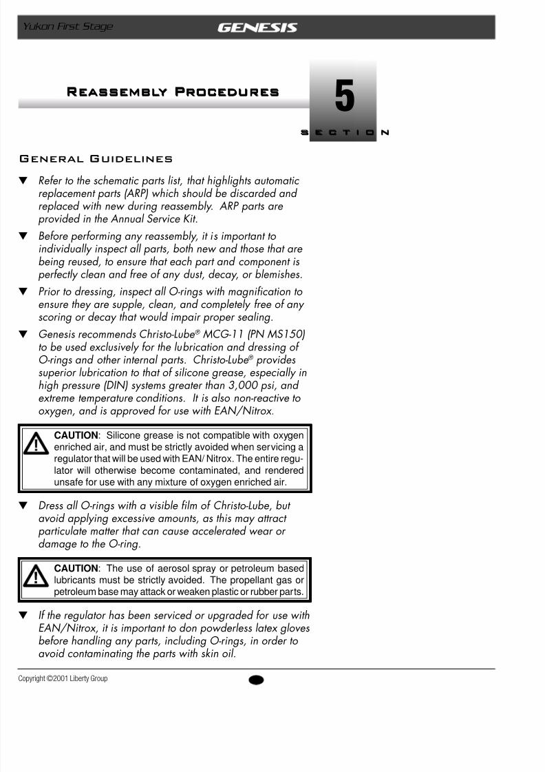
2. Install the high pressure seat(20) into the end of the pishaft, and check to ensure it is seated flush with no visprotrusion (see Fig. 8).
3. Set the end cap(24) on a flat surface with the open endfacing up. Place the head of the piston inside the cap that it rests perfectly level above the threads, and thengently press the piston straight down into place until itfully seated.
CAUTION: Be careful to prevent the piston from becomingcocked at an angle as the head travels past the threads ofthe end cap. The O-ring could otherwise become unseatedor damaged, and metal on metal contact could cause dam-age to the piston or the end cap.
4. Fit the styling ring(17) over the end cap, so that it restsevenly over the circumference of the shoulder.
5. Over the support post inside the intermediate pressurechamber of the first stage body, install the same color(thickness) and number of spring isolators(18) that wedisassembled from the high pressure chamber.
CAUTION: Unless the spring has been replaced with new,it is very important to reinstall the same number and colorcombination of spring isolators as the original quantity thatwas removed during the disassembly procedure. No morethan two spring isolators may be used between the springand the body, and no more than one spring isolator may beused between the spring and the piston.
6. Apply a light film of lubricant to both ends of thespring(19), and place the spring down over the supporpost inside the high pressure cavity of the body.
7. Place the remaining spring isolator directly over the tothe spring.
8. Hold the body stable with the open intermediate pressuend facing straight up, and position the end cap over thbody so that the piston shaft is aligned through the cen
Fig. 8 – HP Seat Installation
8/6/2019 Yukon 1st Stage
http://slidepdf.com/reader/full/yukon-1st-stage 28/35
28opyright ©2001 Liberty Group
Yukon First Stage
Fig. 10 – Torquing Yoke Retainer
Fig. 9 – End Cap Installation
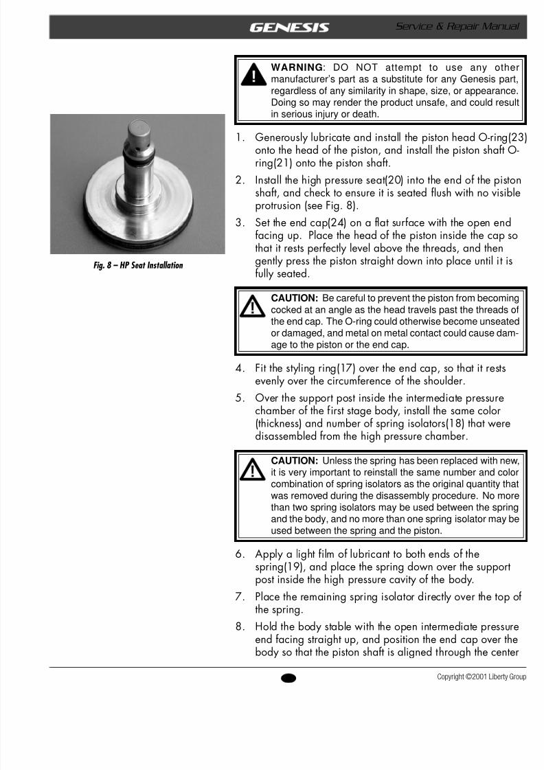
of the spring. Mate the end cap onto the body and firmlypress downward while turning it clockwise to engage thethreads (see Fig.9). Continue turning by hand until snug.
9. Fit the styling cup(11) onto the high pressure end of thefirst stage.
10. Using a vise mounting tool, secure the first stage in a visewith the high pressure end facing straight up.
11. Reassembly of the Yoke Connectora. Install the O-ring(7) into the yoke retainer(8), followed
by the conical filter(6). Closely examine the retainingring(5) to compare the difference of one side, which isflat, from the other which is rounded. Using snap ringpliers, install the retaining ring into the groove abovethe filter, with the flat side facing out.
b. Install the smaller main seal O-ring(9) into the groove inthe bottom of the yoke retainer, and the larger O-ring(10) onto the shoulder at the base of the threads.
c. Being careful to ensure that the O-rings remain properlyseated, insert the threaded end of the yoke retainerthrough the bottom of the yoke(4), and mate the yokeretainer into the inlet port of the first stage body. Turnthe retainer clockwise by hand until snug.
d. Apply a torque wrench with the 1" Yoke Nut Socket(PN 20-155-500) and 3"x a " Socket Drive Extension
(PN 20-156-50). Tighten the yoke retainer to a torquemeasurement of 24 foot-lbs (± 1). (See Fig. 10.)e. Fit the strap of the dust cap(3) over the threads of the
yoke screw(2) with the dimple facing up, and mate the yoke screw into the yoke. Turn the screw one to tworevolutions clockwise to engage the threads.
12. Reassembly of the DIN Connectora. Install both O-rings(4e) and filter(4d) into the filter
housing(4g).b. Mate the filter housing into the inlet port of the first
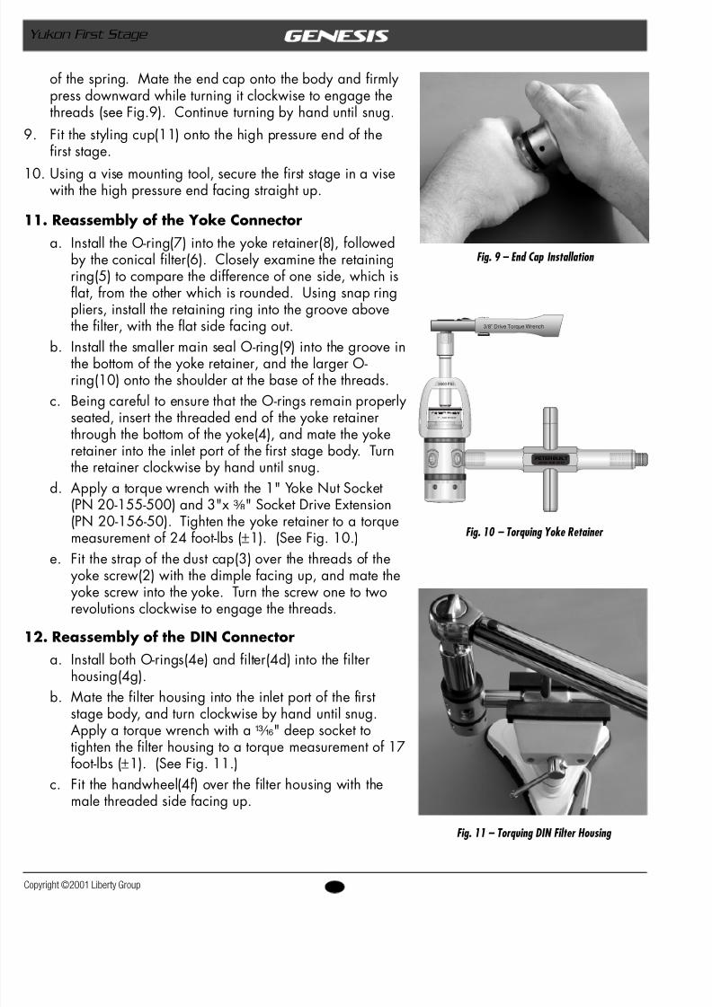
stage body, and turn clockwise by hand until snug.Apply a torque wrench with am " deep socket totighten the filter housing to a torque measurement of 17foot-lbs (± 1). (See Fig. 11.)
c. Fit the handwheel(4f) over the filter housing with themale threaded side facing up.
PETER BUILT(419) 468-2212
3/8” Drive Torque Wrench
P E T E R B U I LT
1" - SIX POINT
3500 PSI
Fig. 11 – Torquing DIN Filter Housing
8/6/2019 Yukon 1st Stage
http://slidepdf.com/reader/full/yukon-1st-stage 29/35
29 Copyright ©2001 Liberty
Service & Repair Manual
d. Install both O-rings(4c&4a) onto the filter retainer(Mate the filter retainer into the filter housing, and tclockwise by hand until snug. Apply a torque wrenwith 4 " hex key socket to tighten the filter retainer torque measurement of 130 inch-lbs (± 10).
13. Mate the crescent spanner of the First Stage Wrench (P30-600-200) over the end cap(24) to engage the pin wione of the bore holes, and hold the tool securely engagWhile holding the tool securely engaged, turn the end clockwise only until it has reached the extent of its threngagement, and do not tighten beyond snug.
14. Loosen the vise to remove the first stage, and remove tvise mounting tool.
15. Lubricate and install the O-rings(23&33) onto all hoseport plugs. Install the LP hoses and port plugs(22&34
their respective ports in the first stage. Apply a calibrtorque wrench with® " (4mm) hex key socket (or apprpriate size crow foot for hoses) to tighten the port plugand hoses to a torque measurement of 38 inch-lbs (± 2).
w After completing the reassembly of the first stage, procto Section 6 – Final Testing
8/6/2019 Yukon 1st Stage
http://slidepdf.com/reader/full/yukon-1st-stage 30/35
30opyright ©2001 Liberty Group
Yukon First Stage
Final Testing Procedures
CAUTION: If the regulator has been upgraded for use withEAN/ Nitrox, it is important to pressurize and flow test theregulator using only hydrocarbon-free gas. The regulatorwill otherwise become contaminated with hydrocarbons ifnormal compressed air is used. Industrial grade compressedNitrogen is strongly recommended as a less expensive al-ternative to EAN/ Nitrox for the purposes of flow testing.
ntermediate Pressure Test1. Connect a calibrated intermediate pressure test gauge to
the regulator, either with a quick-disconnect inflator hose orwith the female fitting of a second stage LP hose, depend-ing on the connection of the test gauge.
CAUTION : To provide a safety relief valve in the event thatintermediate pressure exceeds 155-170 psi, ensure that afully assembled and properly adjusted second stage is con-nected to the first stage before pressurizing. Failure to re-lieve intermediate pressure that exceeds 400 psi may resultin damage or rupture of the test gauge or LP hose, andcould cause serious personal injury.
2. Initially connect the first stage to a supply of 300 psi fil-tered test gas, and slowly open the supply valve to pressur-ize the first stage. Monitor the IP test gauge to verify thatthe intermediate pressure does not rise above 145 psi.
CAUTION : If the intermediate pressure continues to riseabove 200 psi, immediately shut the test gas supply valve.Refer directly to Table 2 - Troubleshooting , and remedy asneeded before proceeding any further.
3. When the intermediate pressure has been determined tobe 145 psi or less, close the supply valve and purge thesecond stage to depressurize the system. Connect the firststage to a supply of 2,500 - 3,000 psi test gas.
NOTE : Correct intermediate pressure for the Yukon firststage is between 135-145 psi, with a supply pressure of2,500 - 3000 psi.
s e c t i o n
6s e c t i o n
Final Testing Procedures
8/6/2019 Yukon 1st Stage
http://slidepdf.com/reader/full/yukon-1st-stage 31/35
31 Copyright ©2001 Liberty
Service & Repair Manual
4. Open the supply valve again while monitoring the IP tgauge to ensure that the intermediate pressure does norise above 145 psi. If the intermediate pressure risesabove 145 psi, immediately close the supply valve andpurge the system. Refer toTable 2 - Troubleshooting, an
remedy as needed before proceeding.5. Repeatedly purge the second-stage approximately 15-2times to cycle the regulator. Then, check the test gaudetermine whether the intermediate pressure locks upconsistently after each cycle and remains stable at 140(± 5) psi, with no signs of creeping or fluctuation. If thintermediate pressure is not within the specified rangeif it fails to lock up with no creep, refer toTable 2 - Troushooting to determine the cause of the problem. Repeathis procedure after the problem is corrected.
6. After determining that the intermediate pressure holdsstable at 140 ( ± 5) psi, perform the following tests tofurther ensure the absence of leaks.
External Leak Test1. After first stage reassembly and final adjustment of the
second stage has been completed, submerge the entireregulator in a test tank of clean water while pressurizewith 2,500-3000 psi. Observe any bubbles arising frothe submerged regulator over a one minute period. Threcommended time is necessary due to slower bubbleformation that occurs in smaller leaks. Disassemble thregulator at the source of the leak to check sealing sur-faces, assembly sequence and component positioning iorder to correct the problem(s).
NOTE : The location of extremely small leaks can best bedetected by applying a soap solution to the leak area. Be-fore disassembling to correct any leaks, rinse the entire regu-lator thoroughly with fresh water and blow out all residualmoisture with filtered, low-pressure (25 psi) test gas. Referto Table 2 - Troubleshooting.
NOTE: After completing the overhaul service proceduresfor the second stage regulator, it is important to test thecomplete regulator, first and second stage, together as acomplete unit, following the final testing procedures outlinedin the second stage service guide.
This completes the overhaul service procedures foYukon First Stage Regulator
8/6/2019 Yukon 1st Stage
http://slidepdf.com/reader/full/yukon-1st-stage 32/35
32opyright ©2001 Liberty Group
Yukon First Stage
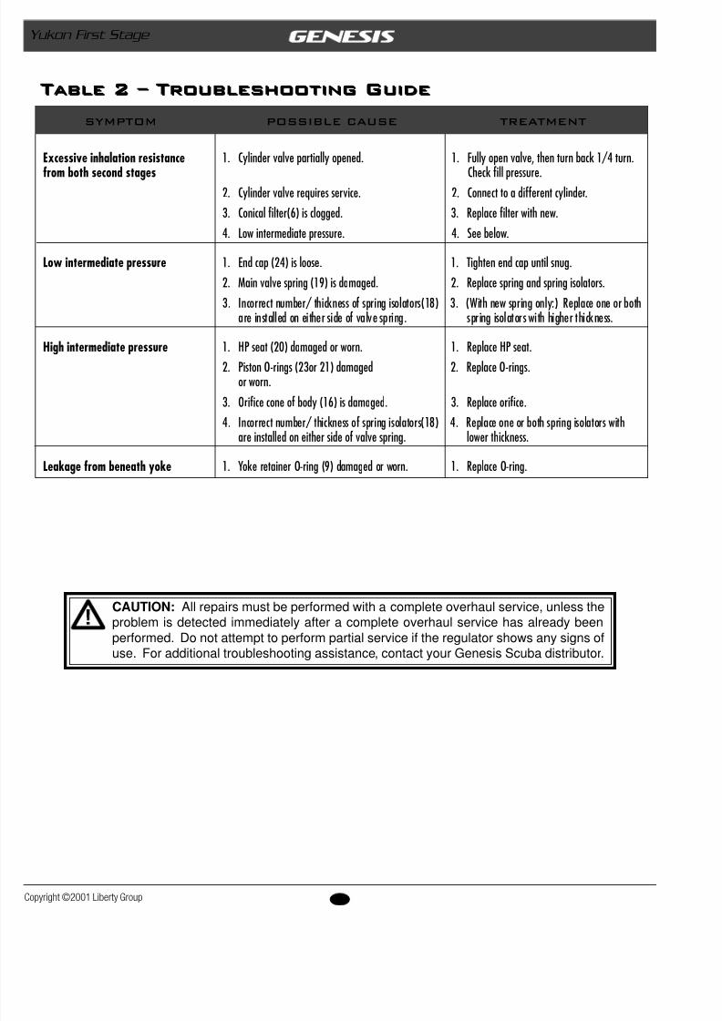
CAUTION: All repairs must be performed with a complete overhaul service, unless theproblem is detected immediately after a complete overhaul service has already beenperformed. Do not attempt to perform partial service if the regulator shows any signs ofuse. For additional troubleshooting assistance, contact your Genesis Scuba distributor.
Excessive inhalation resistance 1. Cylinder valve partially opened. 1. Fully open valve, then turn b
from both second stages Check fill pressure.2. Cylinder valve requires service. 2. Connect to a different cylind3. Conical filter(6) is clogged. 3. Replace filter with new.4. Low intermediate pressure. 4. See below.
Low intermediate pressure 1. End cap (24) is loose. 1. Tighten end cap until snug.2. Main valve spring (19) is damaged. 2. Replace spring and spring is3. Incorrect number/ thickness of spring isolators(18) 3. (With new spring only:)
are installed on either side of valve spring. spring isolators with highe
High intermediate pressure 1. HP seat (20) damaged or worn. 1. Replace HP seat.2. Piston O-rings (23or 21) damaged 2. Replace O-rings.
or worn.3. Orifice cone of body (16) is damaged. 3. Replace orifice.4. Incorrect number/ thickness of spring isolators(18) 4. Replace one or both spri
are installed on either side of valve spring. lower thickness.
Leakage from beneath yoke 1. Yoke retainer O-ring (9) damaged or worn. 1. Replace O-ring.
SYMPTOM POSSIBLE CAUSE TREATMENT
Table 2 – Troubleshooting GuideTable 2 – Troubleshooting Guide
8/6/2019 Yukon 1st Stage
http://slidepdf.com/reader/full/yukon-1st-stage 33/35
33 Copyright ©2001 Liberty
Service & Repair Manual
1
2
3
4
4b
4c
4d
4e
4f
4g
4e
5
10
9
8
7
6
11 12
13
14 15
18
19
18
17
16
2021
22
23
24
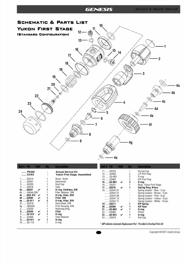
Schematic & Parts List
Yukon First Stage(Standard Configuration)
* ARP indicates Automatic Replacement Part - Provided in Over
Schematic & Parts List
Yukon First Stage(Standard Configuration)
Ref # PN *ARP Qty Description Ref # PN *ARP Qty Description
....... PK300 - Annual Service Kit
....... GXXX - Yukon First Stage, Assembled
1 ....... G5213 1 Decal - Knob2 ....... G5201 1 Handwheel
3 ....... G5205 1 Dust Cap4 ....... G6316 1 Yoke4a ......G6347 1 O-ring, Urethane, DIN4b ...... G4544-200 1 Filter Retainer, DIN4c ......GG2-012 1 O-ring, Vi ton, DIN4d ......G4546 1 Filter, DIN4e ......G2-011 2 O-ring, Vi ton, DIN4f ....... G5218 1 Handwheel, DIN4g ...... GG5226 1 Filter Housing, DIN5 ....... G3530 1 Retaining Ring6 ....... G3545 1 Filter7 ....... G2-013 1 O-ring8 ....... G3450 1 Yoke Retainer9 ....... G2-011 1 O-ring
10 ...... G2-115 1 O-ring
11 ...... G5223 1 Styling Cup12 ...... G3463 3 L/P Port Plug13 ...... G3-903 3 O-ring14 ...... G3462 2 H/P Port Plug15 ......G3-904 2 O-ring
16 ...... G5221 1 Body, Yukon First Stage17 ......G5216 1 Styling Ring, Nitrox18 ...... G3547.01 - Spring isolator - Blue - 2 psi
........ G3547.21 - Spring isolator - Brown - 4 psi
........ G3547.08 - Spring isolator - Pink - 6 psi
........ G3547.13 - Spring isolator - Yellow - 8 psi
........ G3547.11 - Spring isolator - White - 10 psi19 ......G5217 1 H/P Spring20 ......G5269 1 H/P Seat21 ......G2-008 1 O-ring22 ...... G5083 1 Piston23 ......G2-023 1 O-ring24 ...... G5224 1 End Cap

8/6/2019 Yukon 1st Stage
http://slidepdf.com/reader/full/yukon-1st-stage 34/35
NOTES
8/6/2019 Yukon 1st Stage
http://slidepdf.com/reader/full/yukon-1st-stage 35/35