Embed Size (px)
Citation preview

1
Mid PresentationOptical Simulation System for Brain
Waves Detection & Measurements
Computer
High speed digital systems laboratoryהמעבדה למערכות ספרתיות מהירות
הטכניון - מכון טכנולוגי לישראלהפקולטה להנדסת חשמל
Technion - Israel institute of technologydepartment of Electrical Engineering
Presenters:Tomer Zilbershtein 038308227Shahar Porat 025137258Supervised by: Yivgeny Rivkin
Winter Semester 2002
2
Short Description
A program, which has a graphical user interface that, allows the user to change different pictures in different sizes and in different frequencies.While changing pictures, the system will generate a synchronized pulse signal to another device, which examines the brain signals.The system main purpose is to check eye vision.
3
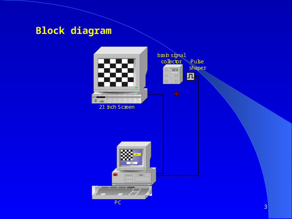
Block diagram
brain signalcollector Pulse
shaper
21 inch Screen
PC
Computer
step 1
pic 2

4
Technical Specification •21 inch monitor
•Angle resolution of line: 5 minutes in distance of 2 meter.
•Synchronize resolution: at most 1mSec.
• The External Stimulator Coupler requires TTL level signal of at least 50 uS duration (>3.5V). The trigger signal must return to the low level before the end of a sweep (256 mS).

5
Hardware Requirements • Power Supply: Vcc (5V)
• Connectors: RS232, BNC
• Data Rate: 20 bps

6
Implementation • Graphical User Interface: using VB.
• Synchronize signal: through the serial port.
• Adjust the signal to TTL level (in Hardware).

7
Serial port output signal

8
Scheme
RS232
MAX12 -> TTL
Driver
Vccinput
IBM PS/2 IBM 3174PC
Brain SignalColector
RS232
BNC

9
Alternative Implementation • Synchronize the output signal using information from the screen.
Picture A: Red line
Picture B: Blue line

10
Video card signal
Measured with 1Mohm probe
Vsync Red line

11
State Machine
Reset
A
B C
ED
Vsync
Vsync Vsync
Red Blue
Red Blue
Red/OutBlue/Out
Input:RedBlueVsyncReset(s.Port)
Output:Out
f = 3/10u = 300KHz
12
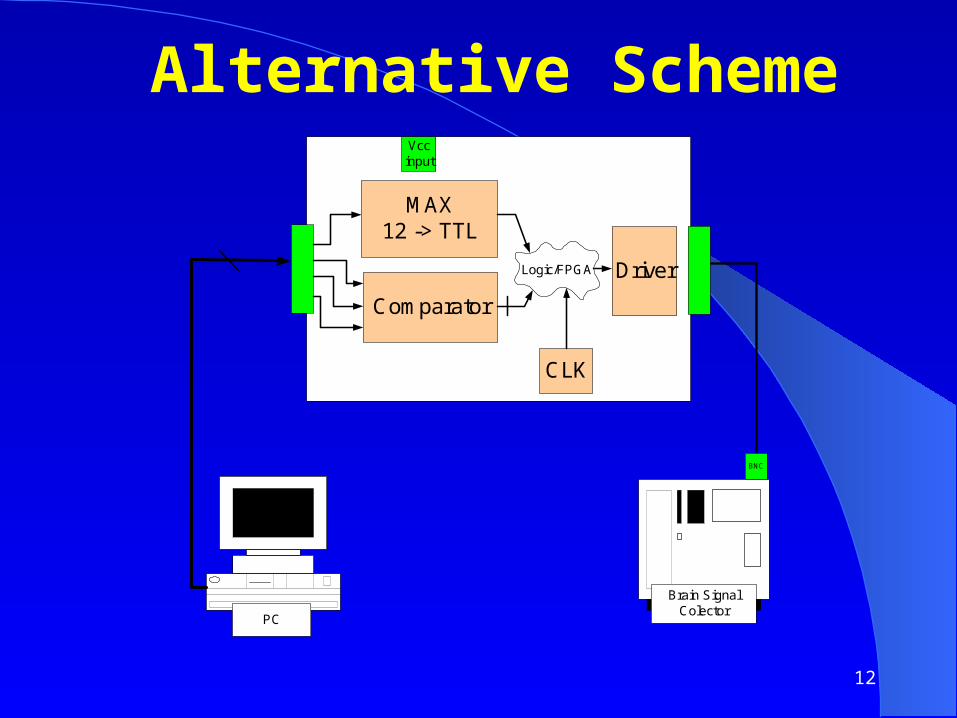
Alternative Scheme
MAX12 -> TTL
Driver
Vccinput
IBM PS/2 IBM 3174PC
Brain SignalColector
Comparator
Logic/FPGA
CLK
BNC

13
Program Flow Chose Program
Edit Steps Edit Program
Create Step
Execute Step
Finish
Run
NextPrevEnd
Stop
LoadExit
14
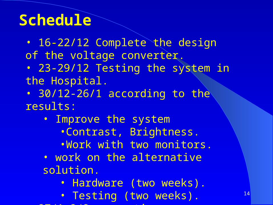
Schedule• 16-22/12 Complete the design of the voltage converter.• 23-29/12 Testing the system in the Hospital.• 30/12-26/1 according to the results:
• Improve the system•Contrast, Brightness.•Work with two monitors.
• work on the alternative solution.• Hardware (two weeks).• Testing (two weeks).
• 27/1-2/2 spare time.