Embed Size (px)
Citation preview
8/12/2019 10179.0000
http://slidepdf.com/reader/full/101790000 1/28
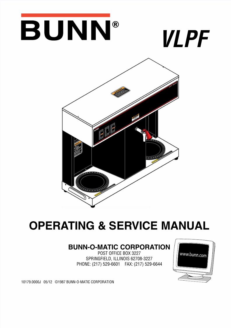
OPERATING & SERVICE MANUAL
BUNN-O-MATIC CORPORATIONPOST OFFICE BOX 3227
SPRINGFIELD, ILLINOIS 62708-3227PHONE: (217) 529-6601 FAX: (217) 529-6644
10179.0000J 05/12 ©1987 BUNN-O-MATIC CORPORATION
VLPF

8/12/2019 10179.0000
http://slidepdf.com/reader/full/101790000 2/28Page 2
10179 030912
BUNN-O-MATIC COMMERCIAL PRODUCT WARRANTYBunn-O-Matic Corp. (“BUNN”) warrants equipment manufactured by it as follows:1) Airpots, thermal carafes, decanters, GPR servers, iced tea/coffee dispensers, MCP/MCA pod brewers thermal serversand Thermofresh servers (mechanical and digital)- 1 year parts and 1 year labor.2) All other equipment - 2 years parts and 1 year labor plus added warranties as specified below: a) Electronic circuit and/or control boards - parts and labor for 3 years.
b) Compressors on refrigeration equipment - 5 years parts and 1 year labor.c) Grinding burrs on coffee grinding equipment to grind coffee to meet original factory screen sieve analysis - parts
and labor for 4 years or 40,000 pounds of coffee, whichever comes first.
These warranty periods run from the date of installation BUNN warrants that the equipment manufactured by it will becommercially free of defects in material and workmanship existing at the time of manufacture and appearing within theapplicable warranty period. This warranty does not apply to any equipment, component or part that was not manufacturedby BUNN or that, in BUNN’s judgment, has been affected by misuse, neglect, alteration, improper installation or operation,improper maintenance or repair, non periodic cleaning and descaling, equipment failures related to poor water quality,damage or casualty. In addition, the warranty does not apply to replacement of items subject to normal use including butnot limited to user replaceable parts such as seals and gaskets. This warranty is conditioned on the Buyer 1) giving BUNNprompt notice of any claim to be made under this warranty by telephone at (217) 529-6601 or by writing to Post OfficeBox 3227, Springfield, Illinois 62708-3227; 2) if requested by BUNN, shipping the defective equipment prepaid to anauthorized BUNN service location; and 3) receiving prior authorization from BUNN that the defective equipment is under
warranty.THE FOREGOING WARRANTY IS EXCLUSIVE AND IS IN LIEU OF ANY OTHER WARRANTY, WRITTEN OR ORAL, EX-PRESS OR IMPLIED, INCLUDING, BUT NOT LIMITED TO, ANY IMPLIED WARRANTY OF EITHER MERCHANTABILITYOR FITNESS FOR A PARTICULAR PURPOSE. The agents, dealers or employees of BUNN are not authorized to makemodifications to this warranty or to make additional warranties that are binding on BUNN. Accordingly, statements by suchindividuals, whether oral or written, do not constitute warranties and should not be relied upon.If BUNN determines in its sole discretion that the equipment does not conform to the warranty, BUNN, at its exclusive op-tion while the equipment is under warranty, shall either 1) provide at no charge replacement parts and/or labor (during theapplicable parts and labor warranty periods specified above) to repair the defective components, provided that this repairis done by a BUNN Authorized Service Representative; or 2) shall replace the equipment or refund the purchase price forthe equipment.THE BUYER’S REMEDY AGAINST BUNN FOR THE BREACH OF ANY OBLIGATION ARISING OUT OF THE SALE OF THISEQUIPMENT, WHETHER DERIVED FROM WARRANTY OR OTHERWISE, SHALL BE LIMITED, AT BUNN’S SOLE OPTIONAS SPECIFIED HEREIN, TO REPAIR, REPLACEMENT OR REFUND.In no event shall BUNN be liable for any other damage or loss, including, but not limited to, lost profits, lost sales, loss ofuse of equipment, claims of Buyer’s customers, cost of capital, cost of down time, cost of substitute equipment, facilitiesor services, or any other special, incidental or consequential damages.
392, AutoPOD, AXIOM, BrewLOGIC, BrewMETER, Brew Better Not Bitter, BrewWISE, BrewWIZARD, BUNN Espress, BUNNFamily Gourmet, BUNN Gourmet, BUNN Pour-O-Matic, BUNN, BUNN with the stylized red line, BUNNlink, Bunn-OMatic,Bunn-O-Matic, BUNNserve, BUNNSERVE with the stylized wrench design, Cool Froth, DBC, Dr. Brew stylized Dr. design,Dual, Easy Pour, EasyClear, EasyGard, FlavorGard, Gourmet Ice, Gourmet Juice, High Intensity, iMIX, Infusion Series, In-tellisteam, My Café, Phase Brew, PowerLogic, Quality Beverage Equipment Worldwide, Respect Earth, Respect Earth with
the stylized leaf and coffee cherry design, Safety-Fresh, savemycoffee.com, Scale-Pro, Silver Series, Single, Smart Funnel,Smart Hopper, SmartWAVE, Soft Heat, SplashGard, The Mark of Quality in Beverage Equipment Worldwide, ThermoFresh,Titan, trifecta, Velocity Brew, A Partner You Can Count On, Air Brew, Air Infusion, Beverage Bar Creator, Beverage ProfitCalculator, Brew better, not bitter., BUNNSource, Coffee At Its Best, Cyclonic Heating System, Daypart, Digital BrewerControl, Nothing Brews Like a BUNN, Pouring Profits, Signature Series, Tea At Its Best, The Horizontal Red Line, Ultra areeither trademarks or registered trademarks of Bunn-O-Matic Corporation.

8/12/2019 10179.0000
http://slidepdf.com/reader/full/101790000 3/28
Page 3
INTRODUCTION This equipment will brew a half-gallon batch of coffee into an awaiting decanter and dispense hot water ondemand for other purposes. It has two warmers to keep the beverage at the right temperature. The brewer isonly for indoor use on a sturdy counter or shelf.
CONTENTSWarranty .................................................................................................2
Introduction and User Notices ................................................................3Electrical, Plumbing Requirements, Operating Controls..........................4Initial Setup, Brew Volume Adjustments .................................................5Coffee Brewing, Cleaning ........................................................................6Troubleshooting ......................................................................................7Service ..................................................................................................13Wiring Diagram .....................................................................................28
USER NOTICESCarefully read and follow all notices on the equipment and in this manual. They were written for your protectionAll notices on the equipment should be kept in good condition. Replace any unreadable or damaged labels.
As directed in the International Plumbing Code of theInternational Code Council and the Food CodeManual of the Food and Drug Administration (FDA),this equipment must be installed with adequate
backflow prevention to comply with federal, stateand local codes. For models installed outside theU.S.A., you must comply with the applicable Plumb-ing /Sanitation Code for your area.
#00656.0001
PN:00658.0000G 02/08 © 1985 BUNN-O-MATIC CORPORATION
#00658.0000
#00882.0000
WARNING!
Fill water tank before turning - on -thermostat or connecting applianceto power source.Use only on a properly protectedcircuit capable of the rated load.Electrically ground the chassis.Follow national/local electrical codes.Do not use near combustibles.
FAILURE TO COMPLY RISKS EQUIPMENT
DAMAGE, FIRE, OR SHOCK HAZARD
READ THE ENTIRE OPERATING MANUAL
BEFORE BUYING OR USING THIS PRODUCT
THIS APPLIANCE IS HEATED WHENEVER
CONNECTED TO A POWER SOURCE00831.0000F 3/98 ©1998 BUNN-O-MATIC CORPORATION
#00831.0000
#12364.0000
10179 05171
8/12/2019 10179.0000
http://slidepdf.com/reader/full/101790000 4/28Page 4
ELECTRICAL REQUIREMENTS
CAUTION - The brewer must be disconnected from the power source until specified in Initial Set-Up.
The brewer has an attached cordset and requires 2-wire, grounded service rated 120 volts ac, 15 amp, singlephase, 60 Hz.
PLUMBING REQUIREMENTS This brewer must be connected to a cold water system with operating pressure between 20(138) and 90psi(620 kPa) from a 1/2” or larger supply line. A shut-off valve should be installed in the line before the brewer.Install a regulator in the line when pressure is greater than 90 psi(620 kPa) to reduce it to 50 psi(345 kPa). Thewater inlet fitting is 1/4” flare.
NOTE - Bunn-O-Matic recommends 1/4” copper tubing for installations of less than 25 feet and 3/8” for morethan 25 feet from the 1/2” water supply line. A tight coil of copper tubing in the water line will facilitate movingthe brewer to clean the counter top. Bunn-O-Matic does not recommend the use of a saddle valve to install thebrewer. The size and shape of the hole made in the supply line by this type of device may restrict water flow.
Plumbing Hook-Up1. Attach the female fitting from the short piece of tubing on the flow control/strainer assembly (supplied)
to the water inlet fitting on the right rear side of the brewer.2. Flush the water line and securely attach it to the flare fitting on the flow control/strainer assembly.3. Turn on the water supply
OPERATING CONTROLS
A. On/Left Switch Placing the switch in the upper position supplies power to the left decanter warmer and enables brewing andrefilling of the tank. Placing the switch in the lower position cuts power to the left decanter warmer and stopsbrewing and refilling of the tank. Stopping a brew cycle after it has been started will not stop the flow of waterinto the funnel until the tank syphons down to its proper level.
NOTE - The On/Left switch must be in the upper position to initiate and complete a brew cycle or to automaticallyrefill the tank after using the hot water faucet.
B. Start Switch Starts a brew cycle when the On/Left switch is in the upper position.
C. Right Switch Placing the switch in the upper position supplies power to the right decanter warmer. Placing the switch inthe lower position cuts power to the right decanter warmer.
10179 051712
As directed in the International Plumbing Code of the International Code Council and the Food Code Manualof the Food and Drug Administration (FDA), this equipment must be installed with adequate backflow pre-vention to comply with federal, state and local codes. For models installed outside the U.S.A., you must
comply with the applicable Plumbing /Sanitation Code for your area.

8/12/2019 10179.0000
http://slidepdf.com/reader/full/101790000 5/28
Page 5
10179 06010
INITIAL SET-UPCAUTION - The brewer must be unplugged throughout the Initial Set-up , except when specified in the instruc-tions.
1. Remove the top lid from the brewer.2. Rotate the control thermostat knob fully counterclockwise to the “OFF” position and replace the top lid.3. Insert an empty funnel into the funnel rails.4. Place a decanter containing a small amount of water on the left warmer.5. Plug in the brewer and place the On/Left switch in the upper position. Water will flow into the tank after a
five second delay and continue until the tank has filled to its capacity. This should take approximately sevenminutes.
NOTE - The On/left switch must be in the upper position to initiate and complete a brew cycle or to automaticallyrefill the tank after using the hot water faucet.
6. Place the On/left switch in the lower position.7. Unplug the brewer.8. Remove the top lid.9. Rotate the control thermostat knob fully clockwise to the “ON” position and replace the top lid.10. Plug in the brewer and wait for the water in the tank to heat to the proper temperature. Some water will drip
from the funnel during this time. This is due to expansion and should not occur thereafter.11. Place an empty decanter under the funnel.12. Place the On/Left switch in the upper position and press the Start switch. Empty the decanter after wate
has stopped flowing from the funnel.13. Allow the water in the tank to reheat to the proper temperature.14. Press the Start switch. Check the water volume in the decanter after water has stopped flowing from the
funnel. It should be 64 ounces.15. If not, unplug the brewer and remove the top lid.16. Adjust the brew timer as required. See Adjusting Brew Volumes. Replace the top lid, plug in the brewer, start
and measure another brew cycle.17. Repeat steps 13-16 until 64 oz. water volume is achieved.
ADJUSTING BREW VOLUMES
CAUTION - Disconnect the power source from the brewer prior to the removal of any panel for the replacementor adjustment of any component.NOTE: Prior to setting or modifying batch sizes, check that the brewer is connected to water supply, the tank isproperly filled, and a funnel and server are in place.1. Modifying batch sizes. To modify a batch volume, first check that the SET/LOCK switch is in the “SET” posi-
tion on the circuit board. To increase a batch size. Press and hold the START or BREW switch until three clicks are heard. Release
the switch (Failure to release the switch within two seconds after the third click causes the volume setting tobe aborted and previous volume setting will remain in memory) and press it again one or more times. Eachtime the switch is pressed, two seconds are added to the brew time period. Allow the brew cycle to finish inorder to verify that the desired volume has been achieved.
To decrease a batch size. Press and release the START or BREW switch once for every two-second intervato be removed from the total brew time period; then immediately press and hold down the START or BREWswitch until three clicks are heard. Release the switch. (Failure to release the switch within two seconds aftethe third click causes the volume setting to be aborted and previous volume setting will remain in memory)Allow the brew cycle to finish in order to verify that the desired volume has been achieved.

8/12/2019 10179.0000
http://slidepdf.com/reader/full/101790000 6/28Page 6
2. Setting batch sizes. To set a batch volume, first check that the SET/LOCK switch is in the “SET” position onthe circuit board. Press and hold the START or BREW switch until three distinct clicks are heard, and thenrelease the switch. (Failure to release the switch within two seconds after the third click causes the volumesetting to be aborted and previous volume setting will remain in memory). View the level of the liquid beingdispensed. When the desired level is reached, turn the ON/OFF switch to “OFF”. The brewer remembers thisvolume and will continue to brew batches of this size until the volume setting procedure is repeated.
NOTE: When brewing coffee, batch volumes will decrease due to absorption by the coffee grounds.3. Setting programming disable feature. If it becomes necessary to prevent anyone from changing brew times
once programmed, you can set the SET/LOCK switch to the “LOCK” position. This will prevent any program-ming to be done until switch is once again placed in the “SET” position.
COFFEE BREWING
1. Insert a BUNN® filter into the funnel.2. Pour the fresh coffee into the filter and level the bed of grounds by gently shaking.3. Slide the funnel into the funnel rails.
4. Place the On/Left switch in the upper position.5. Press the Start switch.6. When brewing is completed, simply discard the grounds and filter.
NOTE - Any attempt to draw hot water from the faucet during a brew cycle will result in a lesser amount of fin-ished beverage in the decanter.
CLEANING1. The use of a damp cloth rinsed in any mild, non-abrasive, liquid detergent is recommended for cleaning all
surfaces on Bunn-O-Matic equipment.
2. Check and clean the sprayhead. The sprayhead holes must always remain open.3. With the sprayhead removed, insert the deliming spring (provided) all the way into the sprayhead tube. Wheninserted properly , no more than two inches of spring should be visible. Saw back and forth five or six times.Then, repeat this step for the airvent tube.
NOTE - In hard water areas, this may need to be done daily. It will help prevent liming problems in the brewerand takes less than a minute.
ADJUSTING BREW VOLUMES(cont)
10179 060100

8/12/2019 10179.0000
http://slidepdf.com/reader/full/101790000 7/28
Page 7
TROUBLESHOOTING A troubleshooting guide is provided to suggest probable causes and remedies for the most likely problemsencountered. If the problem remains after exhausting the troubleshooting steps, contact the Bunn-O-MaticTechnical Services Department.
Inspection, testing, and repair of electrical equipment should be performed only by qualified service person-nel.
All electronic components have 120 volt ac and low voltage dc potential on their terminals. Shorting oterminals or the application of external voltages may result in board failure.
Intermittent operation of electronic circuit boards is unlikely. Board failure will normally be permanent. Ian intermittent condition is encountered, the cause will likely be a switch contact or a loose connection at aterminal or crimp.
Solenoid removal requires interrupting the water supply to the valve. Damage may result if solenoids areenergized for more than ten minutes without a supply of water.
The use of two wrenches is recommended whenever plumbing fittings are tightened or loosened. This wilhelp to avoid twists and kinks in the tubing.
Make certain that all plumbing connections are sealed and electrical connections tight and isolated.
This brewer is heated at all times unless unplugged. Keep away from combustibles.
WARNING • Exercise extreme caution when servicing electrical equipment.
• Unplug the brewer when servicing, except when electrical tests are specied.
• Follow recommended service procedures.
• Replace all protective shields or safety notices.
10179 06010

8/12/2019 10179.0000
http://slidepdf.com/reader/full/101790000 8/28Page 8
TROUBLESHOOTING (cont.)
PROBLEM
Equipment will not operate
Brew cycle will not start
Automatic refill will not operateafter drawing hot water.
PROBABLE CAUSE
1. No power or incorrect voltage
1. No water
2. Water strainer/Flow Control
3. On/Left switch
4. Start switch
5. Brew timer
6. Relay
7. Solenoid valve
1. On/Left switch
REMEDY
(A) Plug in brewer.(B) Check wall outlet for 120V ac(C) Check circuit breaker/fuse.
Check plumbing and shut-offvalves.
(A) Direction of flow arrow mustbe pointing towards brewer.(B) Remove the strainer/Flow con-trol and check for obstructions.Clear or replace.
Refer to Service - On/Left switch
for testing procedures. See page22.
Refer to Service - Start switch fortesting procedures. See page 26.
Refer to Service - Brew timer fortesting procedures. See page 16.
Refer to Service - Relay for testingprocedures. See page 23.
Refer to Service - Solenoid valvefor testing procedures. See page25.
(A) The On/Left switch must bein the upper position for the au-tomatic refill to operate.(B) Refer to Service - On/Leftswitch for testing procedures. Seepage 22.
10179 060100

8/12/2019 10179.0000
http://slidepdf.com/reader/full/101790000 9/28
Page 9
TROUBLESHOOTING (cont.)
PROBLEM
Automatic refill will not operateafter drawing hot water.(cont.)
Water flows into tank continuously(On/left switch “OFF”)
Water flows into tank continuously(On/left switch “ON”)
Water is not hot.
PROBABLE CAUSE
2. Liquid level control system
3. Relay
4. Solenoid valve
1. Solenoid valve
1. Liquid level control system
2. Relay
3. Brew timer
1. Limit thermostatCAUTION: Do not eliminate orbypass limit thermostat. Use only.replacement part #29329.1000
2. Control thermostat
3. Tank heater
REMEDY
Refer to Service - Liquid LeveControl system for testing proce-dures. See page 20.
Refer to Service - Relay for testingprocedures. See Page 23.
Refer to Service - Solenoid valvefor testing procedures. See page25.
Refer to Service - Solenoid valvefor testing procedures. See page25.
Refer to Service - Liquid LeveControl system for testing proce-dures. See page 20.
Refer to Service - Relay for testingprocedures. See page 23.
Refer to Service - Brew timer fortesting procedures. See page 14
Refer to Service - Limit Thermo-stat for testing procedures. Seepage 19.
Refer to Service - Control Ther-mostat for testing proceduresSee page 17.
Refer to Service - Tank Heater fortesting procedures. See page 27
10179 06010

8/12/2019 10179.0000
http://slidepdf.com/reader/full/101790000 10/28Page 10
TROUBLESHOOTING (cont.)
PROBLEM
Decanter warmer is not hot
Spitting or unusual steaming fromsprayhead
Inconsistent beverage level in
decanter
PROBABLE CAUSE
1. Warmer switches
2. Decanter warmers
1. Control thermostat
2. Lime build-upCAUTION: Tank and tank compo-nents should be delimed regularlydepending on local water condi-tions. Excessive mineral build-upon stainless steel surfaces caninitiate corrosive reactions result-ing in serious leaks.
1. Flow control
2. Improper water pressure
REMEDY
(A) The decanter warmer switchmust be in the upper position forthe warmer to operate.(B) Refer to Service - On/Left or
Right switch for testing proce-dures. See page 22 or 24.
Refer to Service - Decanter Warm-er for testing procedures. Seepage 18.
Refer to Service - Control Ther-mostat for testing procedures.See page 17.
Inspect the tank assembly forexcessive lime deposits. Delimeas required.
(A)Direction of flow arrow must be
pointing towards the brewer.(B)Remove the control and checkfor obstructions. Clear or re-place.
Check the operating water pres-sure to the brewer. It must bebetween 20(138) and 90 psi(620kPa).
10179 060100

8/12/2019 10179.0000
http://slidepdf.com/reader/full/101790000 11/28
Page 11
TROUBLESHOOTING (cont.)
PROBLEM
Inconsistent beverage level indecanter (cont.)
Consistently high or low beveragelevel in decanter.
Dripping from sprayhead
Beverage overflows decanter.
Weak beverage
PROBABLE CAUSE
3. Syphon System
1. Brew timer adjustment
1. Syphon System
2. Solenoid valve
1. Beverage left in decanter
2. Incorrect decanter size.
1. Type of paper filters
2. Coffee
3. Sprayhead
REMEDY
Water should flow freely fromthe sprayhead for approximatelytwenty seconds after the brewsolenoid has shut off and then
stop flowing abruptly. The brewermust be level from side-to-side tosyphon properly.
Adjust the brew timer as requiredto achieve the recommended 64oz. for each brew cycle.
Water should flow freely fromthe sprayhead for approximately
twenty seconds after the brewsolenoid has shut off and thenstop flowing abruptly. The brewemust be level from side-to-side tosyphon properly.
Refer to Service - Solenoid valvefor testing procedures. See page25.
The brew cycle should be started
only with an empty decanter undethe funnel.
Use only 64 oz. decanters.
BUNN® paper filters should beused for proper extraction.
A sufficient quantity of fine or dripgrind coffee should be used forproper extraction.
B u n n - O - M a t i c s p r a y h e a d#01082.0000 should be used toproperly wet the bed of groundcoffee in the funnel.
10179 06010

8/12/2019 10179.0000
http://slidepdf.com/reader/full/101790000 12/28Page 12
TROUBLESHOOTING (cont.)
PROBLEM
Weak beverage (cont.)
Brewer is making unusual noises
PROBABLE CAUSE
4. Funnel loading
5. Water temperature
1. Solenoid valve
2. Plumbing lines
3. Water supply
REMEDY
The BUNN® paper filter should becentered in the funnel and the bedof ground coffee leveled by gentleshaking.
Empty a decanter and place it onthe left warmer. Insert an emptyfunnel into the funnel rails. Placethe On/left switch in the upperposition. Press the Start switchand check the water temperatureimmediately below the sprayheadwith a thermometer. The readingshould not be less than 195° F.
Adjust the control thermostatslightly clockwise to increase thewater temperature.
The nut on top of the solenoidvalve must be tight or it will vibrateduring operation.
Plumbing lines should not be rest-ing on the counter top.
(A) The brewer must be connectedto a cold water line.(B) Water pressure to the brew-er must not be higher than 90psi(620 kPa). Install a regulatorif necessary to lower the work-ing pressure to approximately 50psi(345kPa).
10179 060100

8/12/2019 10179.0000
http://slidepdf.com/reader/full/101790000 13/28
Page 13
SERVICE
This section provides procedures for testing andreplacing various major components used in thisbrewer should service become necessary. Refer toTroubleshooting for assistance in determining thecause of any problem.
COMPONENT ACCESS
WARNING - Unplug the brewer before the removal ofany panel or the replacement of any component
The On/Left switch, Start switch, Right switch,solenoid valve, brew timer, liquid level control compo-nents, relay, control thermostat, limit thermostat, andtank heater are located in the hood. Access is gainedby removing the top lid, attached with two #4-40 slot-
ted-head screws.
WARNING - Inspection, testing, and repair of electri-cal equipment should be performed only by qualifiedservice personnel. The brewer should be unpluggedwhen servicing, except when electrical tests are re-quired and the test procedure specifically states toplug in the brewer.
CONTENTS
Brew Timer .....................................................14Control Thermostat .........................................17Decanter Warmer(s)........................................18Limit Thermostat.............................................19Liquid Level Control System ...........................20On/Left Warmer Switch ...................................22Relay ...............................................................23Right Warmer Switch ......................................24Solenoid Valve ................................................25Start Switch ....................................................26
Tank Heater .....................................................27Wiring Diagram ...............................................28
FIG. 1 COMPONENT ACCESS
P1956.40
10179 06010

8/12/2019 10179.0000
http://slidepdf.com/reader/full/101790000 14/28Page 14
BREW TIMER (early models)
SERVICE (cont.)
Location:
The brew timer is located in the hood, to the rightof the tank.
Test Procedure:1. Disconnect the brewer from the power source
and separate the polarized, three-pin connectorsbetween the timer and brewer wiring harness androtate the brew timer dial fully counterclockwise.
2. With a voltmeter, check the voltage across sockets2 & 3 (white and black wires) of the female con-nector when the On/Left switch is in the upperposition. Connect the brewer to the power source.The indication must be 120 volts ac.
3. Disconnect the brewer from the power source.
If voltage is present as described, proceed to #4. Ifvoltage is not present as described, refer to the WiringDiagram and check the brewing harness.
4. With a voltmeter, check the voltage across sockets1 & 2 (blue and white wires) of the female con-
nector when the On/Left switch is in the upperposition and the Start switch is pressed to thelower position and held. Connect the brewer to thepower source. The indication must be 120 voltsac until the Start switch is released.
5. Disconnect the brewer from the power source.
If voltage is present as described, reconnect the po-larized, three-pin connectors, and proceed to #6. Ifvoltage is not present as described, refer to the WiringDiagram and check the brewer wiring harness.
5
WHI to Relay Coil
BLK to Relay Coil
P1 BLU/BLK to Start SwitchP2 WHI to Liquid Level
BoardP3 BLK to Relay
P1980.80
FIG. 3 BREW TIMER WIRING
OLD STYLE
6. Disconnect the in-line connectors on the blackand white wires from the timer to the wiring har-ness.
7. With a voltmeter, check the voltage across theblack and white wires when the On/Left switch is inthe upper position and the Start switch is pressed
to the lower position and released. Connect thebrewer to the power source. The indication mustbe 120 volts ac for approximately 20 seconds andthen return to its previous indication.
8. Disconnect the brewer from the power source.
If voltage is present as described, the brew timer isoperating properly. Reset the timer dial as required,to obtain the desired brew volume. If voltage is notpresent as described, replace the brew timer.
Removal and Replacement:1. Separate all connectors between the brewer wiring
harness and the timer.2. Remove the two #8-32 nuts holding the timer to
the inside of the hood.3. Install the new timer circuit board as described
in Late Model Timer section on the followingpages.
4. Refer to FIG. 5 when reconnecting the wires.5. Install the Timer Setting decal provided with the
replacement timer kit, on the bottom of the topcover.6. Adjust the timer as required. Refer to Late Model
Timer section on the following pages.
P1979.75
FIG. 2 BREW TIMER
10179 060100

8/12/2019 10179.0000
http://slidepdf.com/reader/full/101790000 15/28
Page 15
BREW TIMER (cont.)(late models)
10179 12170
P2172.80
SERVICE (cont.)
Location: The brew timer is located in the hood, to the rightof the tank.
Test Procedures:1. Disconnect the brewer from the power source and
remove the top cover.2. With a voltmeter, check the voltage across termi-
nals TL1 and TL2 when the “ON/OFF” switch isin the “ON” position. Connect the brewer to the
power source. The indication must be 120 voltsac.
3. Disconnect the brewer from the power source.
If voltage is present as described, proceed to #4.If voltage is not present as described, refer to the Wir- ing Diagram and check the brewer wiring harness.
4. Disconnect the white/blue wire from terminal TL3and the blue wire from terminal TL5. Check forcontinuity across the two wires when the startswitch is pressed to the “START” position.
If continuity is present as described, reconnect thewires and proceed to #5.If continuity is not present as described, refer to theWiring Diagram and check the brewer wiring har-ness.
FIG. 4 BREW TIMER
5. With a voltmeter, check the voltage across terminals TL1 and TL4 when the “ON/OFF” switch isin the “ON” position. Connect the brewer to thepower source. The indication must be 0 volts.
If voltage is as described, proceed to #6.
If voltage is not as described, disconnect the brewerfrom the power source and replace the timer.
6. With a voltmeter, check the voltage across terminals TL1 and TL4 when the “ON/OFF” switchis in the “ON” position. Connect the brewer tothe power source and press the start switch. Theindication must be 120 volts ac.
If voltage is present as described, the brew timer isoperating properly. Reset the timer as required, to
obtain the desired brew volume. If voltage is not present as described, disconnectthe brewer from the power source and replace thetimer.
Removal and Replacement:NOTE: Do not remove or install wires while timer boardis installed. Pressure applied to one side may causedamage to the board.1. Remove the two #8-32 nuts securing circuit board
to the hood.2. Remove circuit board and spacers (as required).3. Remove all wires from the timer.4. Attach all wires to the replacement timer board
prior to installation to the component mountingbracket. Refer to FIG. 5 when reconnecting thewires.
5. Install new circuit board with spacers (as required)to the hood.
6. Adjust the timer as described below.
Timer Setting:NOTE: Prior to setting or modifying volumes, checkthat the brewer is connected to water supply, thetank is properly filled, and a funnel and server are inplace.NOTE: All volume settings must be done with thesprayhead installed.

8/12/2019 10179.0000
http://slidepdf.com/reader/full/101790000 16/28Page 16
1. Modifying brew volumes. To modify a brew vol-ume, first check that the SET/LOCK switch is in the“SET” position on the circuit board.
To increase a brew volume, place the ON/OFF
switch in the “ON” position, press and hold the STARTswitch until three clicks are heard. Release the switchand press it again one or more times. (Failure to re-lease the switch within two seconds after the third clickcauses the volume setting to be aborted and previousvolume setting will remain in memory) Each time theswitch is pressed, two seconds are added to the brewtime period. Allow the brew cycle to finish in order toverify that the desired volume has been achieved.
To decrease a brew volume, place the ON/OFFswitch in the “ON” position, press and release theSTART switch once for every two-second intervalto be removed from the total brew time period; thenimmediately press and hold down the START switchuntil three clicks are heard. Relase the switch. (Failureto release the switch within two seconds after thethird click causes the volume setting to be abortedand previous volume setting will remain in memory).Allow the brew cycle to finish in order to verify thatthe desired volume has been achieved.
2. Setting brew volumes. To set a brew volume,first check that the SET/LOCK switch is in the “SET”position on the circuit board. Place the ON/OFF switchin the “ON” position, press and hold the START switchuntil three distinct clicks are heard and then releasethe switch. (Failure to release theh switch within twoseconds after the third click causes the volume settingto be aborted and previous volume setting will remainin memory.View the level of the liquid being dispensed. When
the desired level is reached, turn the ON/OFF switchto “OFF”.NOTE: Several ounces of water will continue to sy-
BREW TIMER (cont.)(late models)
SERVICE (cont.)
phon from the tank after turning the switch “OFF”.The brewer remembers this volume and will continueto brew batches of this size until the volume settingprocedure is repeated.NOTE: When brewing coffee, volume will decreasedue to absorption by the coffee grounds.
3. Setting programming disable feature. If it be-comes necessary to prevent anyone from changingbrew time once programmed, you can set the SET/ LOCK switch to the “LOCK” position. This will preventany further programming until switch is once againput into the “SET” position.
BLU wire from TL5 to Start SwitchWHI/GRN wire from TL4 to A on Relay CoilBLK wire from TL3 to B on Relay Coil
WHI wire from TL2 to J3 Liquid Level BoardWHI/RED wire from TL1 to J2 Liquid Level Board
FIG. 5 DIGITAL TIMER WIRING
P2037
10179 121704

8/12/2019 10179.0000
http://slidepdf.com/reader/full/101790000 17/28
Page 17
B U N N O
F F H
I
SERVICE (cont.)
Location: The control thermostat is located on the rear ofthe hood to the right of the tank.
Test Procedure:1. Disconnect the brewer from the power source and
remove the black wire from the control thermo-stat.
2. With a voltmeter, check the voltage across theblack wire removed from the control thermostat
and the white wire on the tank heater terminal.Connect the brewer to the power source. Theindication must be 120 volts ac.
3. Disconnect the brewer from the power source.
If voltage is present as described, reconnect the blackwire and proceed to #4.If voltage is not present as described, refer to the Wir-ing Diagram and check the brewer wiring harness.
4. Remove the blue wire from the control thermo-stat.
5. With a voltmeter, check the voltage across theexposed terminal of the control thermostat andthe white wire on the tank heater terminal whenthe control thermostat is turned “ON” (fully clock-wise). Connect the brewer to the power source.The indication must be 120 volts ac. Voltage mustnot be indicated across these terminals when thethermostat is turned “OFF” (fully counterclock-wise).
6. Disconnect the brewer from the power source.
If voltage is present as described, reconnect the bluewire, the control thermostat is operating properly.If voltage is not present as described, replace thecontrol thermostat.
Removal and Replacement1. Remove both wires from the control thermostat
terminals.2. Remove the thermostat bulb by firmly pulling
up on the capillary tube at the tank lid. This wildisengage the grommet from the tank lid.
3. Remove the two #8-32 screws holding the controthermostat to the brewer housing.
4. Slide the grommet to the red mark on the capillarytube.
5. Insert the bulb through the hole in the tank lid andpress the grommet firmly and evenly so the groovein the grommet fits into the tank lid.
6. Carefully bend the capillary tube so the tube andbulb inside the tank are in a vertical position.
NOTE - Make sure the capillary tube is away from anyelectrical termination and is not kinked.
7. Fasten the new control thermostat to the brewehousing.
8. Refer to FIG. 7 when reconnecting the wires.9. Readjust the control thermostat dial as required.
FIG. 6 CONTROL THERMOSTATP2172.80
10179 06010
CONTROL THERMOSTAT
BLU to Limit Thermo-stat
BLK to Cordset
FIG. 7 CONTROL THERMOSTAT TERMINALS
P1981

8/12/2019 10179.0000
http://slidepdf.com/reader/full/101790000 18/28Page 18
SERVICE (cont.)
DECANTER WARMERS
FIG. 8 DECANTER WARMERSP1956.40
Left Warmer
Right Warmer
WHI/VIO to On/Left Switch
WHI to Right WarmerWHI to Cordset
BRN/BLK to RightSwitch
WHI to On/Left SwitchWHI to Left Warmer
FIG. 9 WARMER ELEMENT TERMINALS
P1982
Location: The decanter warmers are located in the base ofthe brewer.
Test Procedure:1. Disconnect the brewer from the power sourceand remove the three #4-40 screws attaching thesuspect warmer.
2. Bring the warmer assembly out the top of thebase.
3. Disconnect both wires from the warmer. Make surethat the wire ends do not touch any metal surfaceof the brewer.
4. With a voltmeter, check the voltage across thetwo wires removed from the warmer when the
appropriate warmer switch (on/left or right) is inthe upper position. The voltage must be 120 voltsac.
10179 060100
5. Connect the crewer to the power source.
If voltage is present as described, proceed to #6.If voltage is not present as described, refer to the Wir-ing Diagram and check the brewer wiring harness.
6. Disconnect the brewer from the power source.7. Check for continuity across the two terminals on
the warmer.
If continuity is present as described, reconnect thewires to the terminals, the warmer is operating prop-erly.If continuity is not present as described, replace thewarmer.
Removal and Replacement1. Remove the three #4-40 slotted-head screws
holding the warmer to the brewer base.2. Bring the warmer out the top of the base.3. Disconnect both wires from the warmer.4. Refer to FIG. 9 when reconnecting the wires and
orienting the warmers.5. Place the warmer into the base and securely attach
it using the three #4-40 screws.

8/12/2019 10179.0000
http://slidepdf.com/reader/full/101790000 19/28
Page 19
SERVICE (cont.)
LIMIT THERMOSTAT
Location: The limit thermostat is located on the tank lidbetween the tank heater terminals.
Test Procedure:
1. Disconnect the brewer from the power source andremove the blue wire from the limit thermostat.
2. With a voltmeter, check the voltage across theblue wire removed from the limit thermostat andthe white wire on the tank heater terminal whenthe control thermostat is turned “ON” (fully clock-wise). Connect the brewer to the power source.The indication must be 120 volts ac.
3. Disconnect the brewer from the power source.
PN:658
FIG. 10 LIMIT THERMOSTAT
P1983.40
If voltage is present as described, reconnect the bluewire and proceed to #4.If voltage is not present as described, refer to the Wir-ing Diagram and check the brewer wiring harness.
4. Remove the black wire from the limit thermo-
stat.5. With a voltmeter, check for voltage across theexposed terminal of the limit thermostat and thewhite wire on the tank heater terminal when thecontrol thermostat is turned “ON” (full clockwise)Connect the brewer to the power source. Theindication must be 120 volts ac.
6. Disconnect the brewer from the power source.
If voltage is present as described, reconnect the blackwire, the limit thermostat is operating properly.
If voltage is not present as described, replace the limitthermostat.
Removal and Replacement:1. Remove both wires from the limit thermostat
terminals.2. Carefully slide the limit thermostat out from unde
the retaining clip.3. Carefully slide the new limit thermostat into the
retaining clip.4. Refer to FIG. 11 when reconnecting the wires.
FIG. 11 LIMIT THERMOSTAT TERMINALSP1984.60
BLU to ControlThermostatBLK to Tank
Heater
10179 06010
8/12/2019 10179.0000
http://slidepdf.com/reader/full/101790000 20/28Page 20
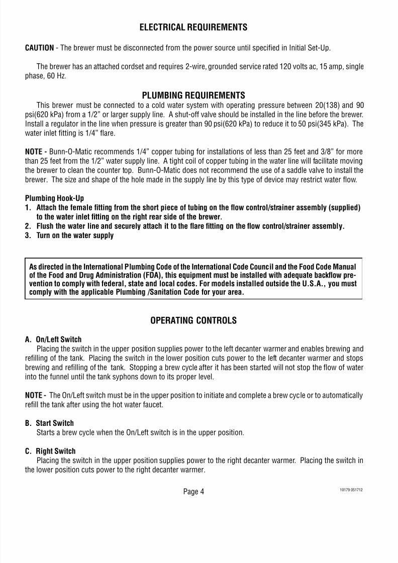
LIQUID LEVEL CONTROL SYSTEM
Location: The liquid level control system is composed of thecircuit board in the right front corner of the hood andthe probe in the tank lid.
Test Procedure:1. Disconnect the brewer from the power sourceand remove the wires from terminals 1 & 4 of thecircuit board.
2. With a voltmeter, check the voltage across termi-nals 2 & 3 when the On/Left switch is in the upperposition. Connect the brewer to the power source.The indication must be 120 volts ac.
3. Disconnect the brewer from the power source.
If voltage is present as described, proceed to #4.
If voltage is not present as described, refer to the Wir-ing Diagram and check the brewer wiring harness.
4. Reconnect the brown/white wire to terminal 1.5. Carefully connect a piece of insulated jumper wire
to terminal 4. Keep the other end of this wire away
FIG. 12 LIQUID LEVEL PROBE & CONTROL BOARD
PN: 658
B U N N O
F F H
I
P2173.80
10179 121704
SERVICE (cont.)
from any metal surface of the brewer.6. With a voltmeter, check the voltage across termi-
nals 1 & 3 when the On/Left switch is in the upperposition. Connect the brewer to the power source.The indication must be 120 volts ac after a delayof approximately 5 seconds.
7. Touch the end of the jumper wire to the brewerhousing. The indication must be zero.
8. Move the jumper wire away from the brewer hous-ing. The indication must again be 120 volts ac aftera delay of approximately 5 seconds.
9. Disconnect the brewer from the power source andremove the jumper wire from terminal 4.
If voltage is present as described, the liquid level con-trol board is operating properly, proceed to #10.If voltage is not present as described, replace the liquidlevel control board.
10. Reconnect the pink wire to terminal 4.11. Gently pull the probe out of the tank lid and inspect
for corrosion. Replace it if necessary.12. Place the probe so that neither end is in contact
with any metal surface of the brewer.13. With a voltmeter, check the voltage across termi-
nals 1 & 3 when the On/Left switch is in the upperposition. Connect the brewer to the power source.
The indication must be 120 volts ac after a delayof approximately 5 seconds.
14. Touch the probe’s flat end to the brewer housing.The indication must be zero.
15. Move the probe’s flat end away from the brewerhousing. The indication should again be 120 voltsac after a delay of approximately 5 seconds.
16. Disconnect the brewer from the power source.
If voltage is present as described, reinstall the probe,the liquid level control system is operating properly.
If voltage is not present as described, check the pinkprobe wire and/or replace the probe.

8/12/2019 10179.0000
http://slidepdf.com/reader/full/101790000 21/28
Page 21
SERVICE (cont.)
LIQUID LEVEL CONTROL SYSTEM (cont.)
Removal and Replacement:1. Remove all wires from the liquid level control
board terminals.2. Remove the two #8-32 slotted-head screws hold-
ing the circuit board to the brewer hood.3. Install the new circuit board to the hood, making
sure that the two lock-washers are in place belowthe board and above the spacers.
4. Refer to FIG. 13 when reconnecting the wires.
BRN/WHI to Relay (Term. #2)
WHI/RED to Start SwitchWHI/RED to Relay(Term. #5)
WHI to TimerWHI to Solenoid
PNK to Probe
FIG. 13 LIQUID LEVEL CONTROLBOARD TERMINALS
P1985.70
10179 12170
8/12/2019 10179.0000
http://slidepdf.com/reader/full/101790000 22/28Page 22
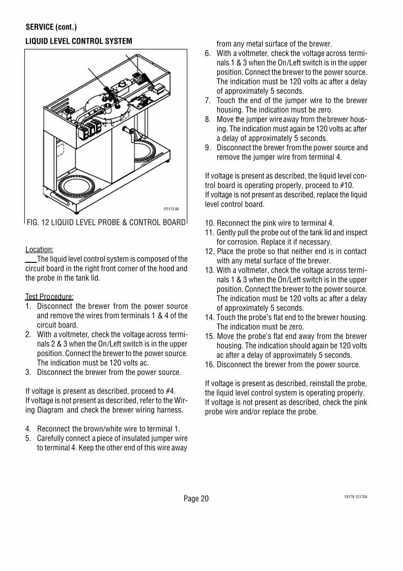
If continuity is not present as described, replace theswitch.
Removal and Replacement:
1. Remove all wires from the switch terminals.2. Compress the clips inside the hood and gently
push the switch through the opening.3. Push the new switch into the opening and spread
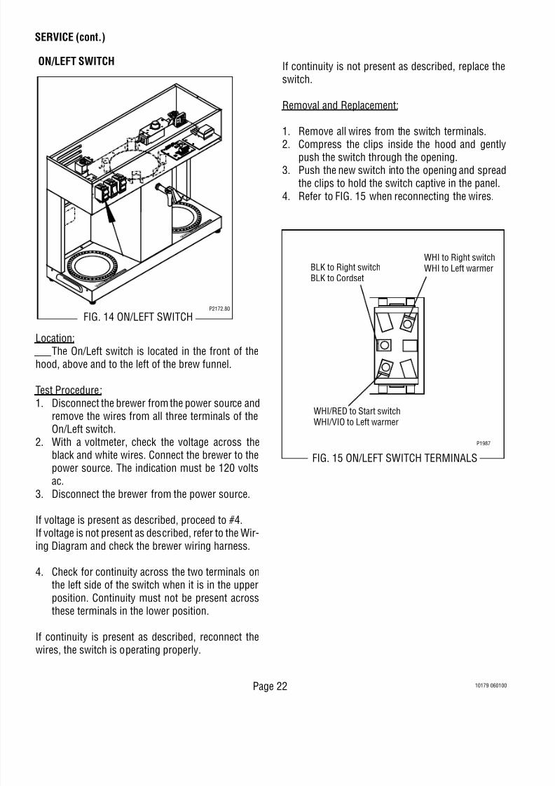
the clips to hold the switch captive in the panel.4. Refer to FIG. 15 when reconnecting the wires.
FIG. 15 ON/LEFT SWITCH TERMINALS
WHI to Right switchWHI to Left warmerBLK to Right switch
BLK to Cordset
WHI/RED to Start switchWHI/VIO to Left warmer
P1987
SERVICE (cont.)
Location: The On/Left switch is located in the front of thehood, above and to the left of the brew funnel.
Test Procedure:1. Disconnect the brewer from the power source and
remove the wires from all three terminals of theOn/Left switch.
2. With a voltmeter, check the voltage across theblack and white wires. Connect the brewer to thepower source. The indication must be 120 voltsac.
3. Disconnect the brewer from the power source.
If voltage is present as described, proceed to #4.If voltage is not present as described, refer to the Wir-
ing Diagram and check the brewer wiring harness.
4. Check for continuity across the two terminals onthe left side of the switch when it is in the upperposition. Continuity must not be present acrossthese terminals in the lower position.
If continuity is present as described, reconnect thewires, the switch is operating properly.
ON/LEFT SWITCH
P2172.80
FIG. 14 ON/LEFT SWITCH
10179 060100

8/12/2019 10179.0000
http://slidepdf.com/reader/full/101790000 23/28
Page 23
SERVICE (cont.)
RELAY
FIG. 16 RELAYP2172.80
Location: The relay is located in the right rear corner of thehood.
Test Procedures1. Disconnect the brewer from the power source.2. With a voltmeter, check the voltage across termi-
nals A & B in the lower corners of the relay whenthe On/Left switch is in the upper position andthe Start switch is pressed to the lower positionand released. Connect the brewer to the power
source. The indication must be 120 volts ac forthe approximate setting of the brew timer and thenreturn to zero.
3. Disconnect the brewer from the power source.
If voltage is present as described, proceed to #4.If voltage is not present as described, refer to the Wir-ing Diagram and check the brewer wiring harness.
4. Remove the black and white wires from terminalsA & B.
5. Check for continuity across terminals A & B of therelay.
If continuity is present as described, reconnect theblack and white wires and proceed to #6.If continuity is not present as described, replace therelay.
6. Remove the brown/white, white/red, and white/ blue wires from terminals 2, 5 & 7 of the relay.
10179 12170
7. Check for continuity across terminals 2 & 7 whenthe On/Left switch is in the upper position onlyuntil the Start switch is pressed to the lowerposition and released. Connect the brewer to thepower source. Continuity must return across theseterminals after the approximate setting of the brewtimer.
8. Disconnect the brewer from the power source.
9. Check for continuity across terminals 5 & 7 whenthe On/Left switch is in the upper position and theStart switch is pressed to the lower position andreleased. Connect the brewer to the power sourceContinuity must be present across these terminalsfor the approximate setting of the brew timer.
10. Unplug the brewer.
If continuity is present as described, reconnect thewires, the relay is operating properly.
If continuity is not present as described, replace therelay.
Removal and Replacement:1. Remove all wires from the relay terminals.2. Remove the two #8-32 nuts holding the relay
mounting bracket to the hood.3. Remove the relay from the mounting bracket.4. Securely install the new relay to the mounting
bracket.5. Install the relay mounting bracket to the hood.
6. Refer to FIG. 17 when reconnecting the wires.
FIG. 17 RELAY TERMINALS
P1988.70
BLK to Timer (TL3)
BRN/WHI to LiquidLevel Board (J1)
WHI/RED toLiquid Level Board (J2)WHI/RED to Timer (TL1)
WHI/BLU toSolenoid
WHI/GRN to Timer (TL4)
7
2
5

8/12/2019 10179.0000
http://slidepdf.com/reader/full/101790000 24/28Page 24
Location: The Right switch is located in the front of the hood,above and to the right of the brew funnel.
Test Procedure:1. Disconnect the brewer from the power source and
remove the wires from all three terminals of the
Right switch.2. With a voltmeter, check the voltage across the
black and white wires. Connect the brewer to thepower source. The indication must be 120 voltsac.
3. Disconnect the brewer from the power source.
If voltage is present as described, proceed to #4.If voltage is not present as described, refer to the Wir-ing Diagram and check the brewer wiring harness.
4. Check for continuity across the two terminals onthe left side of the switch when it is in the upperposition. Continuity must not be present acrossthese terminals in the lower position.
WHI Tank Keep Warm Heater LeadWHI to On/Left SwitchWHI to Solenoid
WHI Tank Keep Warm HeaterLead
BLK to On/Left Switch
BRN/BLK to Right Decant-er Warmer
FIG. 19 RIGHT SWITCH TERMINALS
P1987
RIGHT SWITCH
SERVICE (cont.)
FIG. 18 RIGHT SWITCH
P2172.80
10179 060100
If continuity is present as describe, reconnect thewires, the switch is operating properly.If continuity is not present as described, replace theswitch.
Removal and Replacement:
1. Remove all wires from the switch terminals.2. Compress the clips inside the hood and gently
push the switch through the opening.3. Push the new switch into the opening and spread
the clips to hold the switch captive in the panel.4. Refer to FIG. 19 when reconnecting the wires.

8/12/2019 10179.0000
http://slidepdf.com/reader/full/101790000 25/28
Page 25
SERVICE (cont.)
SOLENOID VALVE
PN: 6
58
B U N N O
F F H
I
FIG. 20 SOLENOID VALVE
P2173.80
10179 06010
Location: The solenoid valve is located in the left rear cornerof the hood.
Test Procedures:1. Disconnect the brewer from the power source and
remove both wires from the solenoid valve coilterminals.
2. With a voltmeter, check the voltage across the whiteand white/blue wires when the On/Left switch is inthe upper position and the Start switch is pressedto the lower position and released. Connect thebrewer to the power source. The indication mustbe 120 volts ac for the approximate setting on thebrew timer dial and then return to zero.
3. Disconnect the brewer from the power source.
If voltage is present as described, proceed to #4.If voltage is not present as described, refer to the Wir-ing Diagram and check the brewer wiring harness.
4. Check for continuity across the solenoid valvecoil.
If continuity is present as described, reconnect thewhite and white/blue wires and proceed to #5.If continuity is not present as described, replace thesolenoid valve.
5. Check the solenoid valve for coil action. Connectthe brewer to the power source, place the On/Leftswitch in the upper position, press and release theStart switch. Listen carefully in the vicinity of thesolenoid valve for a “clicking” sound as the coimagnet attracts and after the approximate settingon the brew timer dial, repels the plunger.
6. Disconnect the brewer from the power source.
If the sound is heard as described and water will notpass through the solenoid valve, there may be a block-age in the water line before or after the solenoid valveor, the solenoid valve may require inspection for wearand removal of waterborne particles.If the sound is not heard as described, replace thesolenoid valve.
Removal and Replacement:1. Remove all wires from the solenoid valve coil.2. Turn off the water supply to the brewer.3. Disconnect the water lines to and from the sole-
noid valve.4. Remove the two #8-32 nuts holding the solenoid
valve mounting bracket to the hood.5. Lift out the solenoid valve.6. Remove the solenoid valve from the mounting
bracket.7. Securely install the new solenoid valve to the
mounting bracket.8. Attach the mounting bracket to the hood.9. Securely fasten the water lines to and from the
solenoid valve.10. Refer to FIG. 21 when reconnecting the wires.
WHI to Right SwitchWHI to Liquid LevelControl Board
WHI/BLU to Relay
P1989
FIG. 21 SOLENOID TERMINALS

8/12/2019 10179.0000
http://slidepdf.com/reader/full/101790000 26/28Page 26
START SWITCH
FIG. 22 START SWITCH
P2172.80
BLU to Timer
WHI/ RED to On/ Left SwitchWHI/ RED to Liquid LevelControl Board
P1987
FIG. 23 START SWITCH TERMINAL
SERVICE (cont.)
10179 060100
Location: The Start switch is located in front of the hood,centered above the brew funnel.
Test Procedure:
1. Disconnect the brewer from the power source andremove the wires from both terminals of the Startswitch.
2. Check for continuity across the two terminals onthe switch when it is held in the lower position.Continuity must not be present across these ter-minals in the upper position.
If continuity is present as described, reconnect thewires, the switch is operating properly. (It does notmatter which terminals the wires are installed on).If continuity is not present as described, replace theswitch.
Removal and Replacement:
1. Remove all wires from the switch terminals.2. Compress the clips inside the hood and gently
push the switch through the opening.3. Push the new switch into the opening and spread
the clips to hold the switch captive in the hood.4. Refer to the FIG 23. When reconnecting the
wires.

8/12/2019 10179.0000
http://slidepdf.com/reader/full/101790000 27/28
Page 27
SERVICE (cont.)
PN: 6
58
P1983.40
FIG. 24 TANK HEATER
10179 06010
TANK HEATER
Location: The tank heater is located on the tank lid.
Test Procedure:1. Disconnect the brewer from the power source and
remove both wires from the tank heater.2. With a voltmeter, check the voltage across the
black and white wires removed from the tankheater when the control thermostat is turned “ON”(fully clockwise). Connect the brewer to the powersource. The indication must be 120 volts ac.
3. Disconnect the brewer from the power source.
If voltage is present as described, proceed to #4.If voltage is not present as described, refer to the Wir-ing Diagram and check the brewer wiring harness.
4. Check for continuity across the terminals of thetank heater.
If continuity is present as described, reconnect thewires, the tank heater is operating properly.If continuity is not present as described, replace thetank heater.
NOTE - If the tank heater remains unable to heat,remove and inspect the heater for cracks in thesheath.
Removal and Replacement:1. Remove the white wire from the tank heater ter
minal and the blue wire from the limit thermostatterminals.
2. Gently pull the liquid level probe and thermostatube with grommet out of the tank lid.
3. Disconnect the 1/4” flare fitting on the tank lid inle
fitting.4. Remove the sprayhead and sprayhead nut from
the panel on the bottom of the hood.5. Disconnect the airvent tube from the fitting above
the sprayhead panel.6. Loosen the eight #8-32 nuts on the tank lid and
remove the tank lid.7. Remove the two nuts from the tank heater fit-
tings.8. Remove the tank heater.
9. Install the new tank heater with new sealing washers on the underside of the tank lid.10. Securely tighten the nuts to be certain of a water-
tight seal.11. Reinstall tank lid and secure with eight #8-32
nuts.12. Reinstall the sprayhead tube nut and sprayhead.13. Reinstall the liquid level probe and thermostat into
the tank lid.14. Securely fasten the 1/4” flare fitting to the tank lid
inlet fitting.
15. Refer to FIG. 25 when reconnecting the wires.
BLK to limit thermostat
WHI to Cordset
FIG. 25 TANK HEATER TERMINALS
P1990.70

8/12/2019 10179.0000
http://slidepdf.com/reader/full/101790000 28/28
TL1 TL5 TL3 TL4
TL2
B A
10178.0000E 12/04 © 1988 BUNN-O-MATIC CORPORATION
120 VOLTS A C
2 WIRE + GND
SINGLE PHASE
START SW.
SCHEMATIC WIRING DIAGRAM VLPF


