Embed Size (px)
Citation preview
Burak OzpineciOak Ridge National Laboratory
May 21, 2009
An Active Filter Approach to the Reduction of the DC
Link Capacitor
Project ID: ape_01_ozpineci
This presentation does not contain any proprietary, confidential, or otherwise restricted information
2 Managed by UT-Battellefor the U.S. Department of Energy
Overview
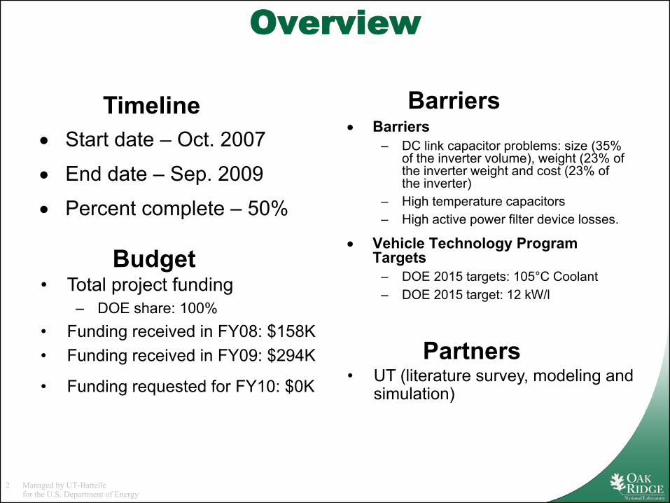
• Start date – Oct. 2007
• End date – Sep. 2009
• Percent complete – 50%
• Barriers– DC link capacitor problems: size (35%
of the inverter volume), weight (23% of the inverter weight and cost (23% of the inverter)
– High temperature capacitors– High active power filter device losses.
• Vehicle Technology Program Targets
– DOE 2015 targets: 105°C Coolant– DOE 2015 target: 12 kW/l• Total project funding
– DOE share: 100%• Funding received in FY08: $158K• Funding received in FY09: $294K
• Funding requested for FY10: $0K
Timeline
Budget
Barriers
• UT (literature survey, modeling and simulation)
Partners
3 Managed by UT-Battellefor the U.S. Department of Energy
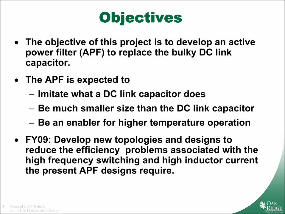
Objectives• The objective of this project is to develop an active
power filter (APF) to replace the bulky DC link capacitor.
• The APF is expected to – Imitate what a DC link capacitor does – Be much smaller size than the DC link capacitor– Be an enabler for higher temperature operation
• FY09: Develop new topologies and designs to reduce the efficiency problems associated with the high frequency switching and high inductor current the present APF designs require.
4 Managed by UT-Battellefor the U.S. Department of Energy
Milestones
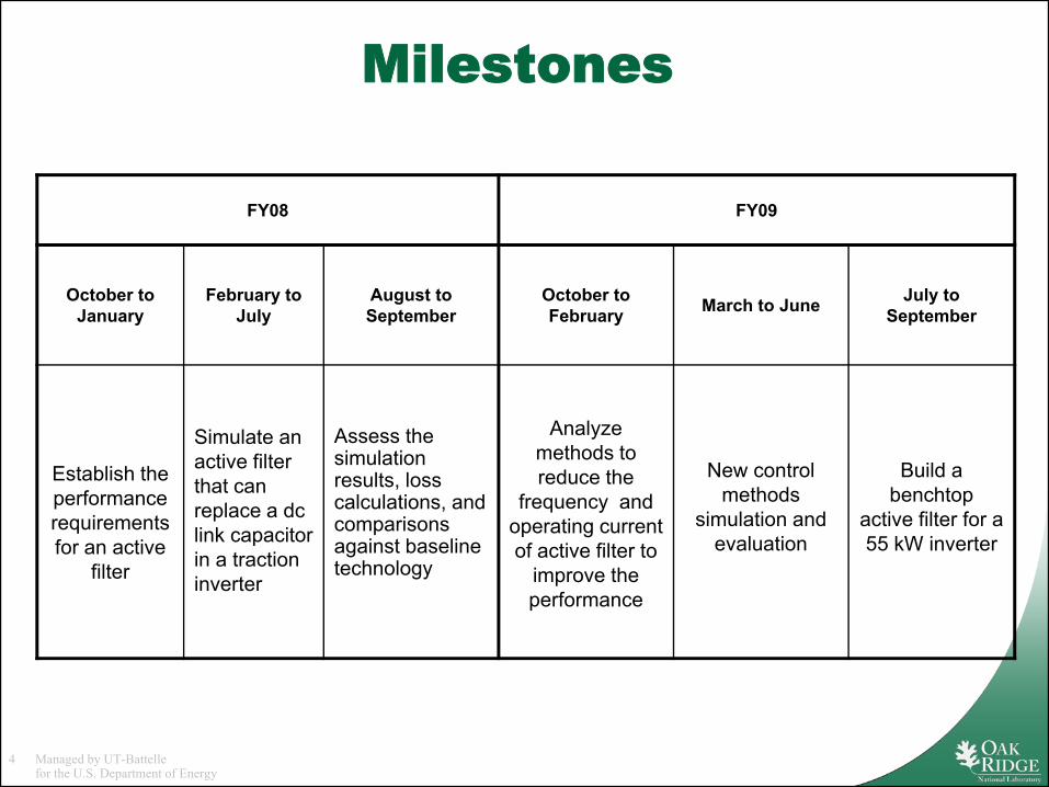
FY08 FY09
October to January
February to July
August toSeptember
October to February March to June July to
September
Establish the performance requirements for an active
filter
Simulate an active filter that can replace a dc link capacitor in a traction inverter
Assess the simulation results, loss calculations, and comparisons against baseline technology
Analyze methods to reduce the
frequency and operating current of active filter to
improve the performance
New control methods
simulation and evaluation
Build a benchtop
active filter for a 55 kW inverter
5 Managed by UT-Battellefor the U.S. Department of Energy
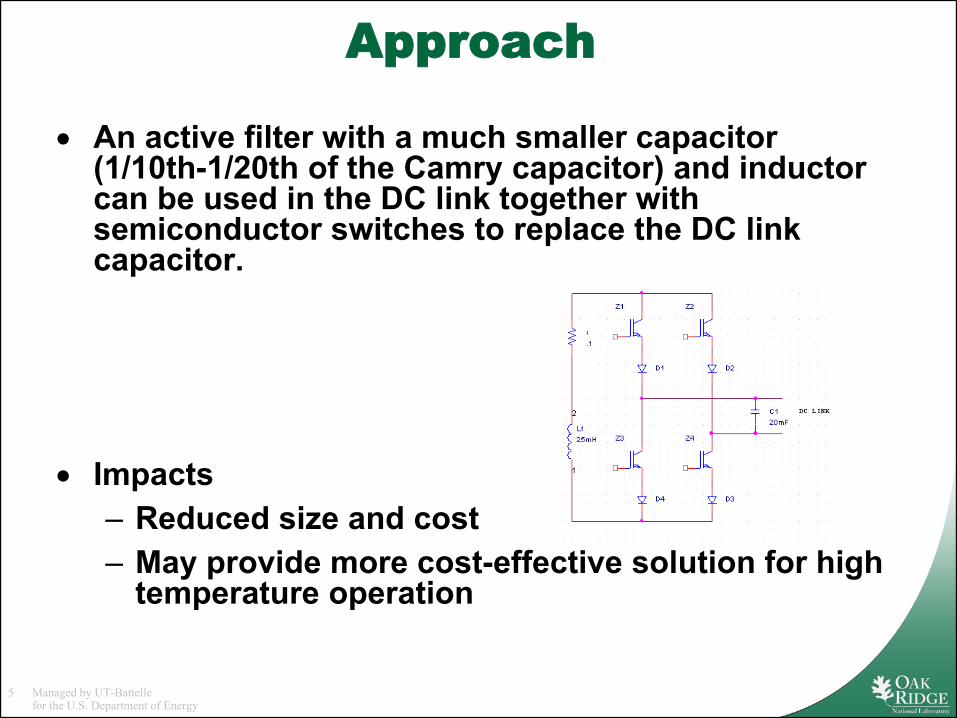
Approach
• An active filter with a much smaller capacitor (1/10th-1/20th of the Camry capacitor) and inductor can be used in the DC link together with semiconductor switches to replace the DC link capacitor.
• Impacts– Reduced size and cost– May provide more cost-effective solution for high
temperature operation
6 Managed by UT-Battellefor the U.S. Department of Energy
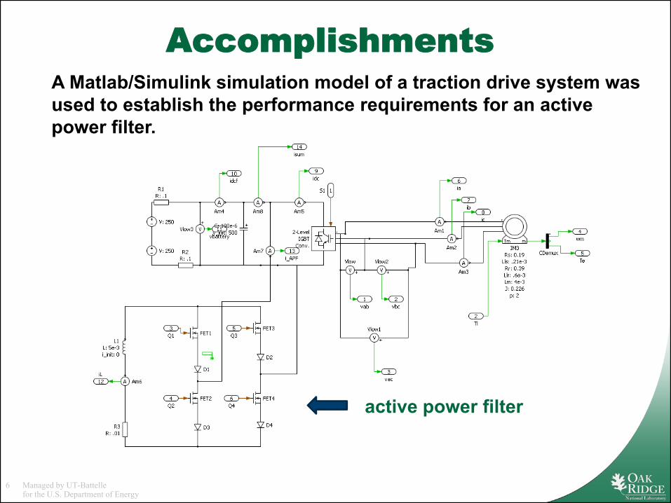
Accomplishments
active power filter
A Matlab/Simulink simulation model of a traction drive system was used to establish the performance requirements for an active power filter.
7 Managed by UT-Battellefor the U.S. Department of Energy
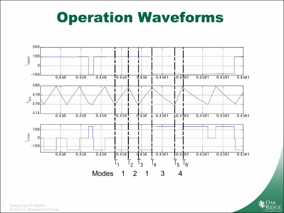
Operation Waveforms
Modes 1 2 1 3 4
8 Managed by UT-Battellefor the U.S. Department of Energy
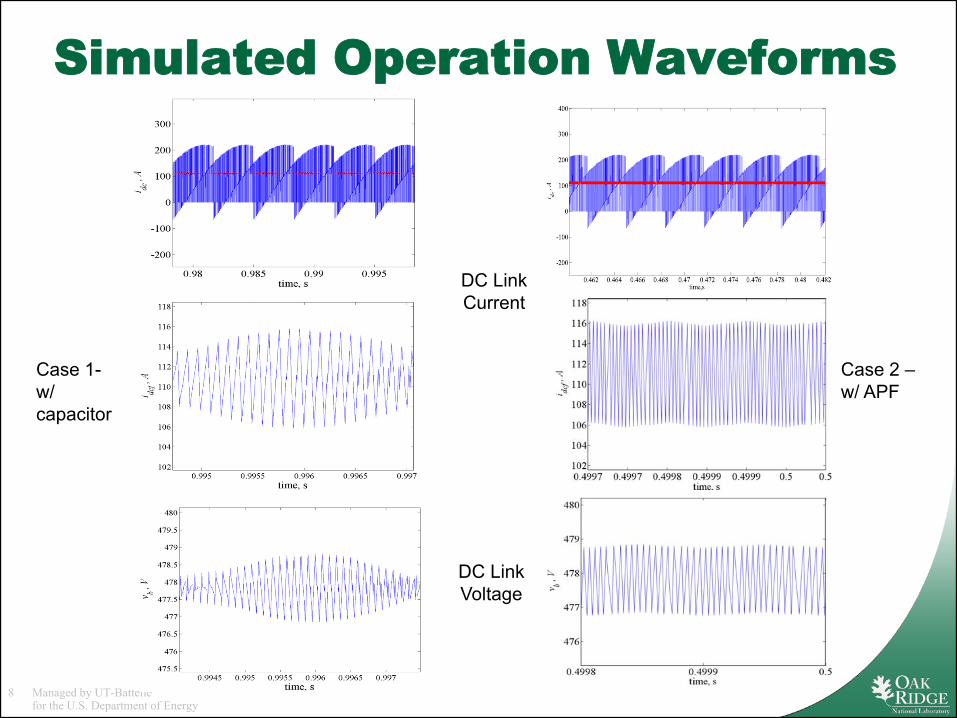
Simulated Operation Waveforms
Case 1-w/ capacitor
Case 2 –w/ APF
DC Link Current
DC Link Voltage
9 Managed by UT-Battellefor the U.S. Department of Energy
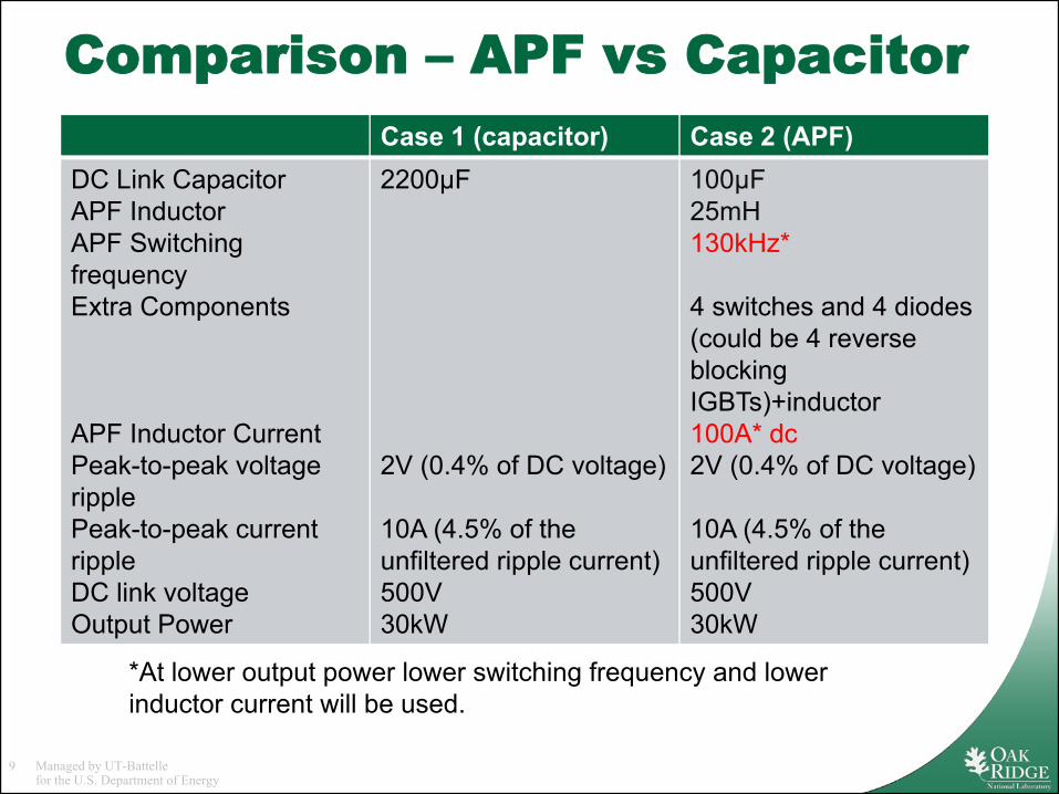
Comparison – APF vs CapacitorCase 1 (capacitor) Case 2 (APF)
DC Link CapacitorAPF InductorAPF Switching frequencyExtra Components
APF Inductor CurrentPeak-to-peak voltage ripplePeak-to-peak current rippleDC link voltageOutput Power
2200μF
2V (0.4% of DC voltage)
10A (4.5% of the unfiltered ripple current)500V30kW
100μF25mH130kHz*
4 switches and 4 diodes (could be 4 reverse blocking IGBTs)+inductor100A* dc2V (0.4% of DC voltage)
10A (4.5% of the unfiltered ripple current)500V30kW
*At lower output power lower switching frequency and lower inductor current will be used.
10 Managed by UT-Battellefor the U.S. Department of Energy
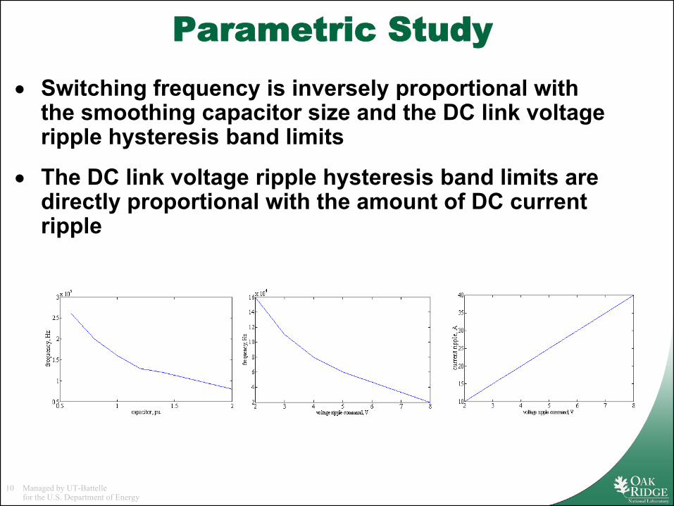
Parametric Study• Switching frequency is inversely proportional with
the smoothing capacitor size and the DC link voltage ripple hysteresis band limits
• The DC link voltage ripple hysteresis band limits are directly proportional with the amount of DC current ripple
11 Managed by UT-Battellefor the U.S. Department of Energy
Efficiency is a problem…
• A 100A - 5mH inductor has an internal resistance of 0.01Ω* and a 2.5mH inductor has half of that value
• Typical losses in the inductor for 100A– 5mH inductor,100W (0.33% for 30kW)– 2.5mH, 50W (0.17% for 30kW)
• The inductor current varies with the output power
• Major losses occur in the devices (IGBTs 1427W – Diodes 460W)
*www.hammondmfg.com
12 Managed by UT-Battellefor the U.S. Department of Energy
Improved APF• A new control method with
– Reduced APF switching frequency – the APF can be switched at the inverter switching frequency
– Reduced inductor current – half of what the original APF control needs
– Slight increase in the DC-link capacitance
• Impact on APF losses compared to the original method– Reduction in switching losses to less than 20%– Reduction in conduction losses to less than 25%
13 Managed by UT-Battellefor the U.S. Department of Energy
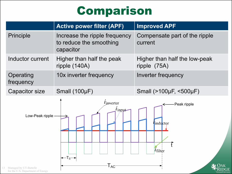
ComparisonActive power filter (APF) Improved APF
Principle Increase the ripple frequency to reduce the smoothing capacitor
Compensate part of the ripple current
Inductor current Higher than half the peak ripple (140A)
Higher than half the low-peak ripple (75A)
Operating frequency
10x inverter frequency Inverter frequency
Capacitor size Small (100μF) Small (>100μF, <500μF)
Peak ripple
Low-Peak ripple
14 Managed by UT-Battellefor the U.S. Department of Energy
Future Work
• Investigate topologies that will reduce the filter inductance requirements and improve the APF efficiency
• Demonstrate the improvements in the topology
• Demonstrate the successful operation of the APF replacing the DC link capacitor
• Develop a topology that is expected to– weigh half as much and– occupy less than half the space, when compared to the
Camry DC link capacitor.
15 Managed by UT-Battellefor the U.S. Department of Energy
Summary• The APF functions as expected but there are
some practical barriers that need to be overcome.– Device losses can be reduced by
• Using less switches and diodes or using a different topology
• Reducing the inductor current• Reducing switching frequency
– Inductance value and associated inductor size• Inductance value determines the stiffness of the dc current
– Low inductance causes low frequency voltage ripple• An optimum inductance value is required
• A new APF control method has been developed that can reduce the losses on the APF and the size of the inductor with a slight increase in the capacitance.


![Title Highly selective photocatalytic reduction of carbon ......6 [12]. In these photocatalytic reaction systems, the reduction of CO 2 to CO (eq. 1) and reduction of proton to the](https://img.pdfslide.tips/doc/110x75/5f8de0d57434da41ef7ddd89/title-highly-selective-photocatalytic-reduction-of-carbon-6-12-in-these.jpg)