Embed Size (px)
Citation preview
8/11/2019 AN2853
http://slidepdf.com/reader/full/an2853 1/12
© Freescale Semiconductor, Inc., 2004. All rights reserved.
Freescale SemiconductorApplication Note
AN2853Rev. 0.1, 10/2004
Table of ContentsThis application note is intended to provide simple C
interface functions to the eTPU Universal Asynchronous
Receiver Transmitter (UART) function. The functions
are usable on any product which contains an eTPU
module. Example code is available for the MPC5554 and
MCF5235 devices. This application note should be read
in conjunction with application note AN2864, “General
C Functions for the eTPU.”
1 Function OverviewThe UART function uses two eTPU channels to provide
a 3-wire (TxD, RxD, and GND) asynchronous serial
interface. It can be used to add serial capability to a
device without a serial port, or to add additional serial
I/O to a device which already has a hardware UART. The
function requires no host CPU intervention during data
frame transmission or reception. One eTPU channel isconfigured to function as the serial transmitter (TxD),
and another eTPU channel is configured to function as a
serial receiver (RxD). The function configures channels
in pairs assuming that there is both transmit and receive
channels. Both the transmit and receive channels have
the same attributes in terms of baud-rate, data-size, parity
1 Function Overview...............................................1
2 UART Overview...................................................2
3 Basic Timing........................................................4
4 Using the Function ..............................................4
4.1 Notes on the Performance and Use of eTPU
UART Function ..................................................5
5 C Level API for eTPU UART Function.................6
5.1 UART Initialization Function ..............................7
5.2 UART Transmit Data Function ...........................7
5.3 UART Receive Data Function............................8
6 Examples of Function Use ..................................8
6.1 MPC5500 Example Code..................................8
6.2 MCF523x Example Code ..................................9
7 Summary.............................................................9
Using the Universal AsynchronousReceiver Transmitter (UART) eTPU
Functionby: Vernon Goler
32-Bit Embedded Controller Division

8/11/2019 AN2853
http://slidepdf.com/reader/full/an2853 2/12
Using the Universal Asynchronous Receiver Transmitter (UART) eTPU Function, Rev. 0.1
UART Overview
Freescale Semiconductor2
etc. However, any channel can be assigned as the transmit channel, and any other channel can be assigned
as the receive channel. Standard baud rates and non-standard baud rates, in addition to parity checking can
be selected.
The main features of the function are as follows:
• Any channel configurable as either a transmitter or a receiver
• Channels assigned in pairs, in which two channels must be utilized for a fully functional UART,containing both a transmitter and a receiver
• Programmable baud rate period over a 23-bit range of TCR1 counts
• Variable data word size from 1 to 23 bits
• Programmable parity
• Double buffered data, both transmitter and receiver contain a shift register, and a data register
• A transmitter channel sets the channel interrupt status (CIS) flag and the data transfer request
status (DTRS) flag to indicate when data has been transferred from the data register to the shift
register, indicating that the data register is available to receive new data to be transmitted.
• A receiver channel sets the channel interrupt status (CIS) flag and the data transfer request status(DTRS) flag to indicate when data has been transferred from the receive shift register to the
receive data register, indicating new receive data is available to be read by the host.
• Supports back-to-back transfers. If data is available in time, the transmitter does not generate an
idle signal, but transmits exactly 1 stop bit, followed by the start bit for the next data word.
• Auto baud rate detection and hardware flow control (Xon, Xoff) are not supported.
• The hardware handshake signals CTS and RTS are not available. However the CIS/ DTRS flags
in channels configured to transmit and receive can be used to emulate that functionality.
2 UART OverviewA UART consists of a transmitter, which transmits serial data via a transmit data (TxD) pin, and a receiver,
which receives serial data via a receive data (RxD) pin. Both transmitter and receiver utilize a shift register
that performs parallel-to-serial and serial-to-parallel conversion. Although a UART interface normally
contains both the transmitter and receiver, implementing a full-duplex UART with the eTPU requires
independent transmitter and receiver channels. This is because each eTPU channel controls only one pin
(a channel can be either a transmitter or a receiver, but not both at the same time). There is no restriction
on which channels can be used to transmit and which channels can be used to receive.
The UART protocol allows selection of a parity bit to detect simple transmission errors. Parity can be
generated and checked in two different ways: odd and even parity. All parity types are supported with the
UART function.The UART protocol is not fixed to a specific number of bits per one data word. Although 8-bit words are
normally used, some applications use 7-bit, 9-bit, or more bits per data word. The UART function can use
data word lengths from 1 to 23 bits. The protocol requires 1 start bit (a high-to-low transition with the low
time lasting 1 bit time) and one stop bit (a low-to-high transition with the high time lasting one bit time)
to frame the data.
8/11/2019 AN2853
http://slidepdf.com/reader/full/an2853 3/12
UART Overview
Using the Universal Asynchronous Receiver Transmitter (UART) eTPU Function, Rev. 0.1
Freescale Semiconductor 3
The UART function is double buffered. Both the transmitter and receiver contain a shift register and a data
register. The host CPU can write new data to the transmit data register while data is being transmitted and
can read data from the receive data register while data is being received.
The UART transmitter sets the channel interrupt status flag and the data transfer request status flag to
indicate when data has been transferred from the transmit data register to the transmit shift register. The
setting of the transmit CIS flag and the DTRS indicates that the transmit data register is available to acceptnew data. If the interrupt status flag will be used in a polling environment, the CIS flag should be cleared
before new data is written to the transmitter. Likewise, if a DMA channel is used to service the UART
channel, the DTRS flag should be cleared by the DMA channel descriptor. When data is written to the
transmit data register, the msb of the 24-bit transmit data register must be written as zero. This is a
handshake signal to the eTPU UART function, indicating that new transmit data to be serially shifted out
has been written.
Likewise, the UART receiver sets the CIS and DTRS flags to indicate the arrival of new data. The CIS and
DTRS flags are set when data has been transferred from the receive shift register to the receive data
register. If the interrupt status flag will be used in a polling environment, the receive CIS flag should be
cleared after reading the received data. If a DMA channel is used to service the UART channel, the DTRS
flag should be cleared by the DMA channel descriptor. The detection of new received data, reading thedata, and clearing the receive CIS flag and DTRS flag must complete before subsequent data is received
to avoid missing data or possibly reading the same data twice. Likewise, any error condition associated
with each received data word must be examined or saved before a subsequent data word is received, or
that error condition will be lost.
The UART function can perform back-to-back transfers. If data is available in time, the transmitter does
not generate an idle line signal, but transmits exactly 1 stop bit followed by the start bit for the next data
frame. An idle line condition only occurs if the transmit data register is empty after the transmit data has
been serially shifted out. The length of a transmit idle line condition is always a multiple of a bit time. The
receiver can handle any length of idle line.
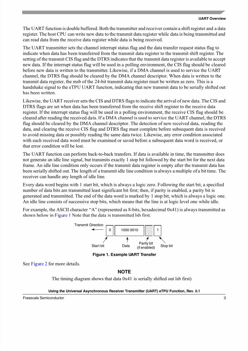
Every data word begins with 1 start bit, which is always a logic zero. Following the start bit, a specifiednumber of data bits are transmitted least significant bit first; then, if parity is enabled, a parity bit is
generated and transmitted. The end of the data word is marked by 1 stop bit, which is always a logic one.
An idle line consists of successive stop bits, which means that the line is at logic level one while idle.
For example, the ASCII character “A” (represented as 8-bits, hexadecimal 0x41) is always transmitted as
shown below in Figure 1 Note that the data is transmitted lsb first.
Figure 1. Example UART Transfer
See Figure 2 for more details.
NOTE
The timing diagram shows that data 0x41 is serially shifted out lsb first)
1000 00100 1
Start bit DataParity bit
(if enabled) Stop bit
Transmit Direction
8/11/2019 AN2853
http://slidepdf.com/reader/full/an2853 4/12
Using the Universal Asynchronous Receiver Transmitter (UART) eTPU Function, Rev. 0.1
Basic Timing
Freescale Semiconductor4
This application note uses the term “bit time” to refer to the time required to transmit or receive one bit of
data. Bit time is determined by baud rate, using the formula:
Bit Time = 1/Baud Rate
The receiver detects a data word by sensing the falling edge (high to low transition) of the start bit. Since
the UART function always treats the first falling edge after the initialization service request as a valid start
bit, a receiver must be enabled only when the line is idle. A received bit is sampled only once,approximately halfway through the bit time. Receiver synchronization occurs every start bit.
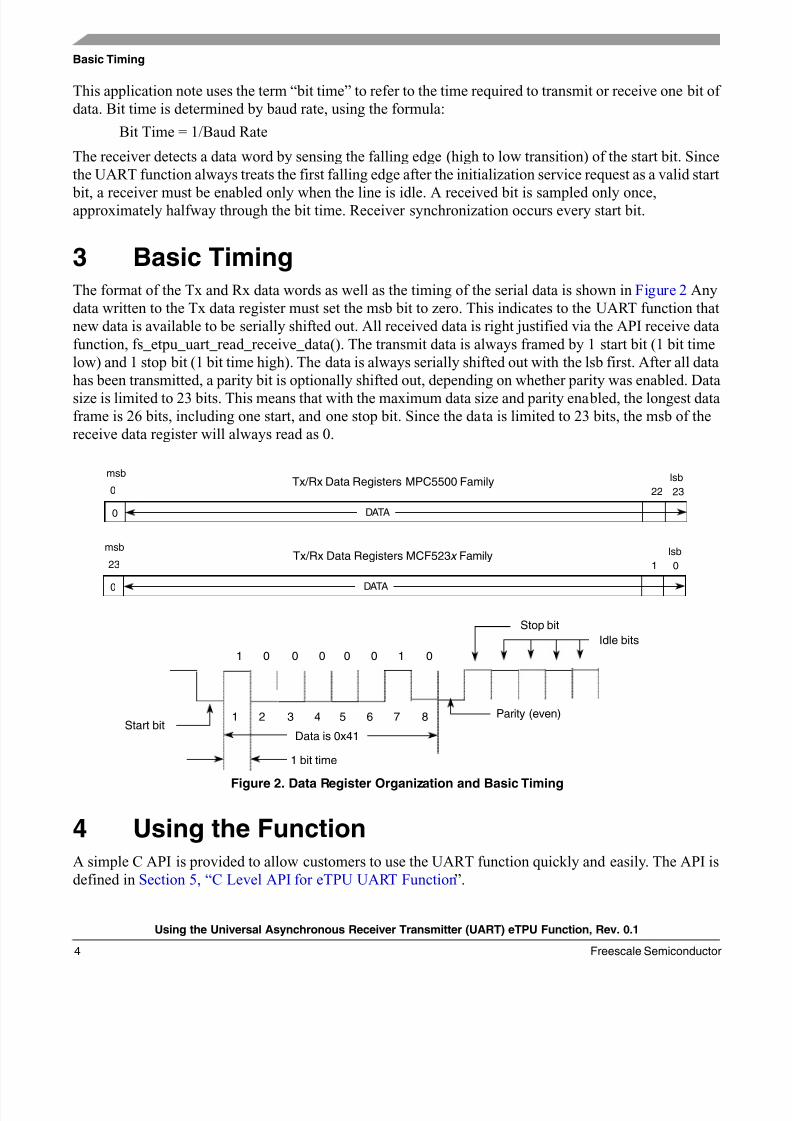
3 Basic TimingThe format of the Tx and Rx data words as well as the timing of the serial data is shown in Figure 2 Any
data written to the Tx data register must set the msb bit to zero. This indicates to the UART function that
new data is available to be serially shifted out. All received data is right justified via the API receive data
function, fs_etpu_uart_read_receive_data(). The transmit data is always framed by 1 start bit (1 bit time
low) and 1 stop bit (1 bit time high). The data is always serially shifted out with the lsb first. After all data
has been transmitted, a parity bit is optionally shifted out, depending on whether parity was enabled. Data
size is limited to 23 bits. This means that with the maximum data size and parity enabled, the longest dataframe is 26 bits, including one start, and one stop bit. Since the data is limited to 23 bits, the msb of the
receive data register will always read as 0.
Figure 2. Data Register Organization and Basic Timing
4 Using the FunctionA simple C API is provided to allow customers to use the UART function quickly and easily. The API is
defined in Section 5, “C Level API for eTPU UART Function”.
msb
0 22 23
0
lsb
DATA
Tx/Rx Data Registers MPC5500 Family
1 0 0 0 0 0 1 0
1 2 3 4 5 6 7 8 Parity (even)
Stop bit
Idle bits
Start bitData is 0x41
1 bit time
msb
23 1 0
0
lsb
DATA
Tx/Rx Data Registers MCF523x Family

8/11/2019 AN2853
http://slidepdf.com/reader/full/an2853 5/12
Using the Function
Using the Universal Asynchronous Receiver Transmitter (UART) eTPU Function, Rev. 0.1
Freescale Semiconductor 5
An initialization function call is used to configure the UART function to match the user's requirements.
Following initialization the transmit function call should be used to send data, and the receive function
used to receive data. The function works in full duplex mode allowing independent sending and sampling
of data. The transmit function and receive function will use the same UART parameters defined during
initialization. In general, the initialization function has been defined assuming a Tx and Rx pair, where
both the transmitter and receiver have the same baud-rate, data size, and parity.
Figure 3 and Table 1 show one possible arrangement.
Figure 3. Function Assignment and Channel Number
When data is transferred from the transmit data register to the transmit shift register, the transmit channel
will assert an interrupt and a DMA request. Likewise, when data is moved from the receive shift register
to the receive data register, the receive channel will assert an interrupt and a DMA request. The DMA
request signal for a given channel may not be connected, depending on the specific integration of the eTPU
block on the microcontroller. The programmer can use either the interrupt DMA request, depending upon
the specific integration configuration.
4.1 Notes on the Performance and Use of eTPU UARTFunction
4.1.1 PerformanceLike all eTPU functions, UART function performance in an application is dependent on the service time
(latency) of other active eTPU channels. This is due to the operational nature of the eTPU scheduler.
When a single UART function is in use and no other eTPU channels are active, the minimum time to both
send and receive a single bit of data is 84 eTPU clocks. This is due to the time taken for the eTPU engine
Table 1. Function Assignment and Channel Number
Pin Function Channel Number
Data Out (Tx) Any Channel
Data In (Rx) Any Channel
eTPU
Data Out (Tx)
Data In (Rx)
Any Channel
Any Channel

8/11/2019 AN2853
http://slidepdf.com/reader/full/an2853 6/12
Using the Universal Asynchronous Receiver Transmitter (UART) eTPU Function, Rev. 0.1
C Level API for eTPU UART Function
Freescale Semiconductor6
to execute the code, and schedule the event(s) required by the UART function. If the time requested
between bit times is less than this minimum, the UART function will not transmit and receives data
correctly. When more eTPU channels are active, performance decreases, as the eTPU engine can only
service one channel at a time. However, worst-case latency in any eTPU application can be closely
estimated. To analyze the performance of an application that appears to approach the limits of the eTPU,
use the guidelines given in the eTPU Reference Manual (ETPURM) and the information provided in the
eTPU UART software release available from Freescale.
The performance of the UART is calculated assuming one transmit and receive channel pair are operating
and no other TPU channels are operating:
• For the MPC5554 with a system frequency of 132 MHz, the maximum baud rate using TCR1
with a timebase_freq of 66 Mhz is 1.45M baud.
• For the MCF5235 with a core frequency of 150 MHz, the maximum baud rate using TCR1 with a
timebase_freq of 37.5 Mhz is 830K baud.
Maximum baud-rate is influenced by compiler efficiency. The above numbers are given for guidance only
and are subject to change. For up to date information, refer to the information provided in the eTPU UART
software release available from Freescale.
5 C Level API for eTPU UART FunctionThe following functions provide easy access for the application developer into the eTPU UART function.
Use of these functions eliminates the need to directly control the eTPU registers. The API consists of three
functions. These functions can be found in etpu_uart.h and etpu_uart.c and are available from Freescale.
In addition, the eTPU compiler generates a file called etpu_UART_auto.h. This file contains information
relating to the eTPU UART function, including details of how the SDM (shared data memory) is organized
and definitions for the various API interface information.
Unless otherwise stated, the function parameter macros are defined in etpu_uart_auto.h.UART Initialization
i nt 32_t f s_et pu_uar t _i ni t ( ui nt 8_t t x_channel , ui nt 8_t r x_channel ,ui nt 8_t pr i or i t y, ui nt 32_t baud_r at e,ui nt 8_t bi t s_per _dat a_wor d, ui nt 8_t par i t y,ui nt 32_t t i mebase_f r eq) ;
UART Transmit Data
voi d f s_et pu_uar t _wr i t e_t r ansmi t _dat a ( ui nt 8_t t x_channel ,ui nt 32_t t r ansmi t _dat a) ;
UART Receive Data
i nt 32_t f s_etpu_uar t _r ead_r ecei ve_dat a ( ui nt 8_t r x_channel , ui nt 8_t *r x_er ror) ;

8/11/2019 AN2853
http://slidepdf.com/reader/full/an2853 7/12
C Level API for eTPU UART Function
Using the Universal Asynchronous Receiver Transmitter (UART) eTPU Function, Rev. 0.1
Freescale Semiconductor 7
5.1 UART Initialization Function
This function is used to initialize two eTPU channels for the eTPU UART function. This function
dynamically allocates SDM, which occurs if the channel has a zero in its channel parameter base address
field. The channel parameter base address field is updated by the API with a non-zero value to point to the
SDM allocated to the channel. The fs_etpu_uart_init API will not allocate new SDM if the channel has a
non-zero value in its channel parameter base address field; this means that the channel has already beenassigned. The channel can be reconfigured to transmit/receive data with a different set of transmit/receive
parameters by calling the fs_etpu_uart_init function again.
This function has seven parameters:
• tx_channel - The channel number of the transmitter, 0-31 for ETPU_A and 64-95 for ETPU_B.
• rx_channel - The channel number of the receiver, 0-31 for ETPU_A and 64-95 for ETPU_B.
• priority - The priority assigned to the channels. This parameter should be assigned a value of:
— FS_ETPU_PRIORITY_HIGH
— FS_ETPU_PRIORITY_MIDDLE
— FS_ETPU_PRIORITY_LOW
— FS_ETPU_PRIORITY_DISABLED
• baud_rate - Baud rate is a measure of the number of times per second a signal in a
communications channel varies or makes a transition between states (states being frequencies,
voltage levels, or phase angles). One baud is one such change. Thus, a 300-baud modem's signal
changes state 300 times each second, while a 600-baud modem's signal changes state 600 times
per second.
• bits_per_data_word - The number of bits to be transmitted or received in one data word. This
bits_per_data_word commonly has a value of eight, because most serial protocols use 8-bit data
words.
• parity - The desired parity. This parameter should be assigned a value of
— FS_ETPU_UART_NO_PARITY
— FS_ETPU_UART_ODD_PARITY
— FS_ETPU_UART_EVEN_PARITY
• timebase_freq - The frequency of the TCR1 timebase for a given operating frequency.
5.2 UART Transmit Data Function
This function is used only after the UART function has been initialized using the fs_etpu_uart_init
function. The configuration selected at initialization will be used for data transfers using this function call.This function call is used to transmit data. The data to be transmitted should be right justified.
This function has two parameters:
• tx_channel - The channel number of the transmitter, 0-31 for ETPU_A and 64-95 for ETPU_B.
• transmit_data - This the actual data to be transmitted. Up to 23 bits of data per data word can be
transmitted. The msb must be written as a zero before the function is called.
8/11/2019 AN2853
http://slidepdf.com/reader/full/an2853 8/12
Using the Universal Asynchronous Receiver Transmitter (UART) eTPU Function, Rev. 0.1
Examples of Function Use
Freescale Semiconductor8
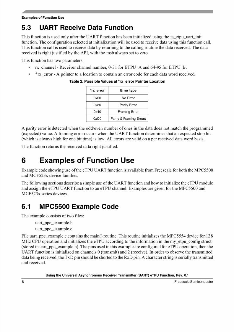
5.3 UART Receive Data Function
This function is used only after the UART function has been initialized using the fs_etpu_uart_init
function. The configuration selected at initialization will be used to receive data using this function call.
This function call is used to receive data by returning to the calling routine the data received. The data
received is right justified by the API, with the msb always set to zero.
This function has two parameters:
• rx_channel - Receiver channel number, 0-31 for ETPU_A and 64-95 for ETPU_B.
• *rx_error - A pointer to a location to contain an error code for each data word received.
A parity error is detected when the odd/even number of ones in the data does not match the programmed
(expected) value. A framing error occurs when the UART function determines that an expected stop bit
(which is always high for one bit time) is low. All errors are valid on a per received data word basis.
The function returns the received data right justified.
6 Examples of Function UseExample code showing use of the eTPU UART function is available from Freescale for both the MPC5500
and MCF523x device families.
The following sections describe a simple use of the UART function and how to initialize the eTPU module
and assign the eTPU UART function to an eTPU channel. Examples are given for the MPC5500 and
MCF523x series devices.
6.1 MPC5500 Example Code
The example consists of two files:
uart_ppc_example.h
uart_ppc_example.c
File uart_ppc_example.c contains the main() routine. This routine initializes the MPC5554 device for 128
MHz CPU operation and initializes the eTPU according to the information in the my_etpu_config struct
(stored in uart_ppc_example.h). The pins used in this example are configured for eTPU operation, then the
UART function is initialized on channels 0 (transmit) and 2 (receive). In order to observe the transmitted
data being received, the TxD pin should be shorted to the RxD pin. A character string is serially transmitted
and received.
Table 2. Possible Values at *rx_error Pointer Location
*rx_error Error type
0x00 No Error
0x80 Parity Error
0x40 Framing Error
0xC0 Parity & Framing Errors
8/11/2019 AN2853
http://slidepdf.com/reader/full/an2853 9/12
Summary
Using the Universal Asynchronous Receiver Transmitter (UART) eTPU Function, Rev. 0.1
Freescale Semiconductor 9
6.2 MCF523x Example Code
The example consists of four files:
uart_mcf_example.h
uart_mcf_example.c
uart_mcf_example_global_etpu_gct.huart_mcf_example_global_etpu_gct.c
File uart_ppc_example.c contains the main() routine. This routine initializes the MCF5235 device for 100
MHz CPU operation and initializes the eTPU according to the information in the my_etpu_config struct
(stored in uart_mcf_example_global_etpu_gct.c). The pins used in this example are configured for eTPU
operation, then the UART function is initialized on channels 0 (Tx) and 2 (Rx). In order to observe the
transmitted data being received, the TxD pin should be shorted to the RxD pin. A character string is serially
transmitted and received.
7 SummaryThis application note provides the user with a description of the universal asynchronous receiver
transmitter (UART) eTPU function and details on its use. The simple C interface for the eTPU UART
function that are provided in the API enable easy implementation of the UART function in user
applications. The function is targeted for the MPC5500 and MCF53x devices, but they can be used with
any device that contains an eTPU.

8/11/2019 AN2853
http://slidepdf.com/reader/full/an2853 10/12
THIS PAGE INTENTIONALLY LEFT BLANK
Using the Universal Asynchronous Receiver Transmitter (UART) eTPU Function, Rev. 0.1
Freescale Semiconductor10
8/11/2019 AN2853
http://slidepdf.com/reader/full/an2853 11/12
THIS PAGE INTENTIONALLY LEFT BLANK
Using the Universal Asynchronous Receiver Transmitter (UART) eTPU Function, Rev. 0.1
Freescale Semiconductor 11
8/11/2019 AN2853
http://slidepdf.com/reader/full/an2853 12/12
How to Reach Us:
Home Page:www.freescale.com
E-mail:[email protected]
USA/Europe or Locations Not Listed:Freescale SemiconductorTechnical Information Center, CH3701300 N. Alma School RoadChandler, Arizona 85224+1-800-521-6274 or [email protected]
Europe, Middle East, and Africa:Freescale Halbleiter Deutschland GmbHTechnical Information CenterSchatzbogen 781829 Muenchen, Germany+44 1296 380 456 (English)+46 8 52200080 (English)+49 89 92103 559 (German)+33 1 69 35 48 48 (French)[email protected]
Japan:Freescale Semiconductor Japan Ltd.Technical Information Center3-20-1, Minami-Azabu, Minato-kuTokyo 106-0047, Japan0120 191014 or +81 3 3440 [email protected]
Asia/Pacific:Freescale Semiconductor Hong Kong Ltd.Technical Information Center2 Dai King StreetTai Po Industrial EstateTai Po, N.T., Hong Kong+800 2666 [email protected]
For Literature Requests Only:Freescale Semiconductor Literature Distribution CenterP.O. Box 5405Denver, Colorado 802171-800-441-2447 or 303-675-2140Fax: [email protected]
Information in this document is provided solely to enable system and
software implementers to use Freescale Semiconductor products. There are
no express or implied copyright licenses granted hereunder to design or
fabricate any integrated circuits or integrated circuits based on the
information in this document.
Freescale Semiconductor reserves the right to make changes without further
notice to any products herein. Freescale Semiconductor makes no warranty,
representation or guarantee regarding the suitability of its products for any
particular purpose, nor does Freescale Semiconductor assume any liability
arising out of the application or use of any product or circuit, and specifically
disclaims any and all liability, including without limitation consequential or
incidental damages. “Typical” parameters that may be provided in Freescale
Semiconductor data sheets and/or specifications can and do vary in different
applications and actual performance may vary over time. All operating
parameters, including “Typicals”, must be validated for each customer
application by customer’s technical experts. Freescale Semiconductor does
not convey any license under its patent rights nor the rights of others.
Freescale Semiconductor products are not designed, intended, or authorized
for use as components in systems intended for surgical implant into the body,
or other applications intended to support or sustain life, or for any other
application in which the failure of the Freescale Semiconductor product could
create a situation where personal injury or death may occur. Should Buyer
purchase or use Freescale Semiconductor products for any such unintended
or unauthorized application, Buyer shall indemnify and hold Freescale
Semiconductor and its officers, employees, subsidiaries, affiliates, and
distributors harmless against all claims, costs, damages, and expenses, and
reasonable attorney fees arising out of, directly or indirectly, any claim of
personal injury or death associated with such unintended or unauthorized
use, even if such claim alleges that Freescale Semiconductor was negligent
regarding the design or manufacture of the part.
Freescale™ and the Freescale logo are trademarks of Freescale
Semiconductor, Inc. All other product or service names are the property
of their respective owners.© Freescale Semiconductor, Inc. 2004. All rights
reserved.
AN2853
Rev. 0.1
10/2004


