Embed Size (px)
Citation preview

��������������� �����������������
������������� ��������������� ��������������
�����������
��������������� ���������������������
�� ����� ������������������������ ���
���������������
��������
�� ����� �����

2
WARNING
WARNING
WARNINGDO NOT OPERATE THIS EQUIPMENT WITHOUT FIRST READING AND
UNDERSTANDING THIS MANUAL. IF YOU ARE UNABLE TOUNDERSTAND THE WARNINGS, CAUTIONS, AND INSTRUCTIONS,
CONTACT A HEALTHCARE PROFESSIONAL, DEALER OR TECHNICALPERSONNEL IF APPLICABLE BEFORE ATTEMPTING TO USE THISEQUIPMENT - OTHERWISE INJURY OR DAMAGE MAY RESULT.
THE INITIAL SET UP OF THIS WHEELCHAIR MUST BE PERFORMED BY AQUALIFIED TECHNICIAN.
PROCEDURES OTHER THAN THOSE DESCRIBED IN THIS MANUALMUST BE PERFORMED BY A QUALIFIED TECHNICIAN.
SPECIAL NOTESWARNING/CAUTION notices as used in this manual apply to hazards or unsafe practices whichcould result in personal injury or property damage.
NOTICE
THE INFORMATION CONTAINED IN THIS DOCUMENT IS SUBJECT TO CHANGE WITHOUT NOTICE.
WHEELCHAIR USER
As a manufacturer of wheelchairs, Invacare endeavors to supply a wide variety of wheelchairs tomeet many needs of the user. However, final selection of the type of wheelchair to be used by anindividual rests solely with the user and his/her healthcare professional capable of making such aselection.
WHEELCHAIR TIE-DOWN RESTRAINTS AND SEAT POSITIONING STRAPS
Invacare recommends that wheelchair users NOT be transported in vehicles of any kind while inwheelchairs. As of this date, the Department of Transportation has not approved any tie-downsystems for transportation of a user while in a wheelchair, in a moving vehicle of any type.
It is Invacare’s position that users of wheelchairs should be transferred into appropriate seating invehicles for transportation and use be made of the restraints made available by the auto indus-try. Invacare cannot and does not recommend any wheelchair transportation systems.
AS REGARDS RESTRAINTS - SEAT POSITIONING STRAPS - IT IS THE OBLIGATION OF THE DME DEALER,THERAPISTS AND OTHER HEALTHCARE PROFESSIONALS TO DETERMINE IF A SEAT POSITIONING STRAPIS REQUIRED TO ENSURE THE SAFE OPERATION OF THIS EQUIPMENT BY THE USER. SERIOUS INJURYCAN OCCUR IN THE EVENT OF A FALL FROM A WHEELCHAIR.
SAVE THESE INSTRUCTIONS

3
TABLE OF CONTENTS
TABLEOF
CONTENTS
TABLE OF CONTENTS
SPECIAL NOTES .......................................... 2
SPECIFICATIONS .......................................... 4
PROCEDURE 1 - GENERAL GUIDELINES ....... 5REPAIR OR SERVICE INFORMATION...............5OPERATING INFORMATION .............................5SAFETY/HANDLING OF WHEELCHAIRS..........7WARNING/CAUTION LABEL LOCATION ......... 10BATTERY BOX SHIPPING INSERTS ............... 11
PROCEDURE 2 - SAFETY INSPECTIONCHECKLIST/TROUBLESHOOTING ............. 12
SAFETY INSPECTION CHECKLIST ................ 12TROUBLESHOOTING GUIDE - MECHANICAL .. 13TROUBLESHOOTING GUIDE - ELECTRICAL... 13CHECKING BATTERY CHARGE LEVEL ........... 13
PROCEDURE 3 - FRONT RIGGINGS ........... 15INSTALLING/REMOVING FOOTRESTS .......... 15ADJUSTING FOOTREST HEIGHT................... 15REPLACING HEEL LOOPS ............................ 16INSTALLING/REMOVING ELEVATING
LEGRESTS .................................................. 16RAISING/LOWERING ELEVATING LEGRESTS
AND/OR ADJUSTING CALFPADS ................. 17ADJUSTING/REPLACING TELESCOPING
FRONT RIGGING SUPPORT ........................ 17ADJUSTING REMOVABLE FOOTBOARD..... 18REMOVING THE REMOVABLE
FOOTBOARD ASSEMBLY FROM THEWHEELCHAIR............................................. 19
INSTALLING/REMOVING THE ONE PIECEFOOTBOARD............................................... 20
ADJUSTING THE ONE PIECE FOOTBOARD -HEIGHT, ANGLE AND DEPTH ...................... 20
REMOVING/INSTALLING THE CALF-PADS ..... 21ADJUSTING THE CALF-PADS ........................ 21FOOTREST ANGLE ADJUSTMENTS .............. 26
PROCEDURE 4 - ARMS............................... 27INSTALLING/REMOVING FLIP BACK
ARMRESTS ................................................. 27ADJUSTING FLIP BACK ARMRESTS .............. 27ADJUSTING CAPTAIN'S SEAT ARMRESTS....... 28
PROCEDURE 5 - CAPTAIN'S SEAT/POSITIONING STRAP .................................. 29
ADJUSTING CAPTAIN'S SEAT ........................ 29REPLACING SEAT POSITIONING STRAP........ 29
PROCEDURE 6 - ELECTRONICS ................ 30PREPARING MKIV JOYSTICK FOR USE ......... 30REPOSITIONING MKIV JOYSTICK.................. 30DISCONNECTING/CONNECTING LIMIT
SWITCH....................................................... 31REPOSITIONING BATTERY CHARGER
CONNECTOR .............................................. 31FUSE REPLACEMENT ................................... 31
PROCEDURE 7 - RETAINING STRAP .......... 32REPLACING BATTERY BOX RETAINING
STRAP ......................................................... 32
PROCEDURE 8 - WHEELS .......................... 33ENGAGING/DISENGAGING MOTORS
WITH CLUTCHES ........................................ 33ENGAGING/DISENGAGING MOTORS
WITH MOTOR LOCKS.................................. 33ADJUSTING FORKS ....................................... 34ADJUSTING THE STABALIZER....................... 34
PROCEDURE 9 - SHROUDS........................ 35REMOVING/INSTALLING SHROUDS .............. 35
PROCEDURE 10 - RECLINER...................... 36RECLINER OPERATION ............................... 36REPLACING BACK OR HEADREST
UPHOLSTERY ............................................ 36ADJUSTING BACK OR HEADREST
UPHOLSTERY ............................................. 37
PROCEDURE 11 - BATTERIES .................... 38INSTALLING/REMOVING BATTERIES INTO/
FROM BATTERY BOXES ............................. 38CONNECTING BATTERY CABLES ............... 39WHEN TO CHARGE BATTERIES ................. 43CHARGING BATTERIES ................................. 43REPLACING BATTERIES................................ 45INSTALLING/REMOVING BATTERY BOXES .... 45INSTALLING/REMOVING BATTERY TRAY ...... 46
LIMITED WARRANTY .................................. 47
NOTE: The following procedures refer to the ProntoR2 and the ProntoR2-250 Series.

4
SPECIFICATIONS
SPECIFICATIONS
SPECIFICATIONS
Seat Width Range:
Seat Depth Range:
Back Height Range Std.:
W/Optional Headrest:
Back Angle Range:
Seat-to-Floor:
Overall Width (No joystick):
Overall Height:
Weight:W/O Batteries:W/Batteries (Gel Cell):Shipping:
Armrests:
Upholstery:
19.5-in. 19.5-in. 19.5-in. 22-in.
17.5-in. 17.5-in. 17.5-in. 19.5-in.
24-in. 24-in. 20-in. 20-in.
N/A N/A 29-in. 29-in.
(55o-114o) (98o) (55o-170o) (55o-114o)
23-in. 21.5-in. 23-in. 23-in.
26-in. 26-in. 26-in. 29-in.
45-in. 45-in. 41.5-in. 41.5-in.
145-lbs220-lbs.270-lbs.
Removable, Flip Back, Fixed orAdjustable Height - Desk and Full Length
Gray Cloth, Grey Vinyl, Tan Vinyl
47.5-inches 34.0-inches(With 8-in. rear casters (With 8-in. rear castersand 93 front riggings) and no front riggings)
7-inch Urethane
12-1/2 x 2-1/4-in. (Std.); 14-in.x 3-in. (Opt.) (Flat Free or Pneumatic)
8 x 1-3/4-in. Semi Pneumatic (Std.), 8 x 2-in. Pneumatic (Opt.)6 x 2-in. Semi Pneumatic (Opt.)
Swingaway, Removable Footboard
22NF Gel Cell/ProntoR2-250 Series
uses U1 Gel Cell
Overall Length (Refer to PER-CENTAGE OF WEIGHT DISTRI-BUTION in PROCEDURE 1 of thismanual.)
Front Stabilizers
Drive Wheels/Tires:
Casters w/Precision SealedBearings:
Footrest/Legrest:
Battery/Size (Not Supplied):
16-24-inches
16-22 inches- in 1-inch increments
16-24 inches- In 1-inch increments
N/A
80o to 100o
- in 5o increments
18.5-inches
24.75 -inches
34.50 -in. - 42.50-in.Back Height
143 lbs.217 lbs.267 lbs.
Removable, Flip Back,Fixed or Adjustable Height- Desk and Full Length
Black Nylon
16-24-inches
16-22 inches- in 1-inch increments
18-26 inches- In 2-inch increments
N/A
90o to 170o
- continuous
18.5-inches
24.75 -inches
36.5 -in. - 44.5-in.Back Height
151 lbs.225 lbs.275 lbs.
Removable, Flip Back,Fixed or Adjustable Height- Desk and Full Length
Black Nylon
ADJUSTABLE SEATCAPTAIN'S SEAT BACK ANGLE RECLINER SEAT
BACK TYPELOW LOW SOLID SEAT HIGH WIDE(EB) (EBSS) (HIB) (WIDEV)
CAPTAIN'S SEAT/ADJUSTABLE SEAT BACK ANGLE/RECLINER
CAPTAIN'S SEAT/ADJUSTABLE SEAT BACK ANGLE/RECLINER
Footnotes:1. Range will vary with battery conditions, surface, ter-
rain and operators weight.
2. Includes seating systems and accessories.
3. Weight limitation varies with motor. Refer toWIEGHT LIMITATION - GENERAL WARNINGSin PROCEDURE 1 of this manual.
PERFORMANCE
Speed (M.P.H.):
Turning Radius:
Range (variable)1:
Weight Limitation2, 3:
0 to 3.6 (250 lb. Limit), 0 to 5.5 (300 lb. Limit), 0 - 3.8 (400 lb. Limit)
> 23-inches (With Removeable Footboard)
17 miles
250 lbs., 300 lbs., or 400 lbs. (See NOTE #3 Below)

5
GENERAL
GUIDELINES
GENERAL GUIDELINES PROCEDURE 1
WARNINGREPAIR OR SERVICE INFORMATIONSet-up of the Electronic Control Unit is to be performed ONLY by a qualified technician. The final tuningadjustments of the controller may affect other activities of the wheelchair. Damage to the equipmentcould occur under these circumstances. If any individual other than an a qualified technician per-forms any work on these units, the warranty is void.
OPERATING INFORMATIONGENERAL WARNINGS
Performance adjustments should only be made by professionals of the healthcare field or persons fullyconversant with this process and the driver's capabilities. Incorrect settings could cause injury to thedriver, bystanders, damage to the chair and to surrounding property.After the wheelchair has been set-up, check to make sure that the wheelchair performs to the speci-fications entered during the set-up procedure. If the wheelchair does NOT perform to specifications,turn the wheelchair OFF immediately and reenter set-up specifications. Repeat this procedure until thewheelchair performs to specifications.DO NOT shift your weight or sitting position toward the direction you are reaching as the wheelchairmay tip over.DO NOT engage or disengage the motor locks/clutches until the power is in the OFF position.DO NOT operate on roads, streets or highways.DO NOT climb, go up or down ramps or traverse slopes greater than 9o.DO NOT attempt to move up or down an incline with a water, ice or oil film.DO NOT attempt to drive over curbs or obstacles. Doing so may cause your wheelchair to turn overand cause bodily harm or damage to the chair.DO NOT use parts, accessories, or adapters other than those authorized by Invacare.DO NOT leave the power button ON when entering or exiting your wheelchair.DO NOT stand on the frame of the wheelchair.DO NOT use the footplate and/or footboard as a platform. When getting in or out of the wheelchair, makesure that the footplates are in the upward position or swing footrests towards the outside of the chair.ALWAYS wear your seat positioning strap.
TIRE PRESSUREDO NOT use your wheelchair unless it has the proper tire pressure (P.S.I.). DO NOT overinflate the tires.Failure to follow these suggestions may cause the tire to explode and cause bodily harm. The recom-mended tire pressure is listed on the side wall of the tire.
ELECTRICALEXTREME care should be exercised when using oxygen in close proximity to electric circuits. Contactyour oxygen supplier for instruction in the use of oxygen.BATTERIESThe warranty and performance specifications contained in this manual are based on the use of deepcycle gel cell or sealed lead acid batteries. Invacare strongly recommends their use as the powersource for this unti.The use of rubber gloves and safety glasses is recommended when working with batteries.
This Procedure Includes the Following:
Repair or Service Information
Operating Information
Safety/Handling of Wheelchairs
Warning/Caution Label Location
Battery Box Shipping Inserts

6
GENERAL GUIDELINESPROCEDURE 1
GENERAL WARNINGS (CONTINUED)Carefully read battery/battery charger information prior to installing, servicing or operating your wheel-chair.GROUNDING INSTRUCTIONS:DO NOT, under any circumstances, cut or remove the round grounding prong from any plug used withor for Invacare products. Some devices are equipped with three-prong (grounding) plugs for protectionagainst possible shock hazards. Where a two-prong wall receptacle is encountered, it is the personalresponsibility and obligation of the customer to contact a qualified electrician and have the two-prongreceptacle replaced with a properly grounded three-prong wall receptacle in accordance with theNational Electrical Code. If you must use an extension cord, use ONLY a three-wire extension cord havingthe same or higher electrical rating as the device being connected. In addition, Invacare has placedRED/ORANGE WARNING TAGS on some equipment. DO NOT remove these tags.
RAIN TESTINVACARE has tested it’s power wheelchairs in accordance with ISO 7176 Part 9 “Rain Test”. This providesthe end user or his/her assistant sufficient time to remove his/her power wheelchair from a rain storm andretain wheelchair operation.DO NOT leave power wheelchair in a rain storm of any kind.DO NOT use power wheelchair in a shower or leave it in a damp bathroom while taking a shower.DO NOT leave power wheelchair in a damp area for any length of time.Direct exposure to rain or dampness will cause the chair to malfunction electrically and mechanically;may cause the chair to prematurely rust.Check to ensure that the battery covers are secured in place, joystick boot is NOT torn or cracked wherewater can enter and that all electrical connections are secure at all times.DO NOT use the joystick if the boot is torn or cracked. If the joystick boot becomes torn or cracked,replace IMMEDIATELY.
WEIGHT TRAININGInvacare DOES NOT recommend the use of its wheelchairs as a weight training apparatus. Invacarewheelchairs have NOT been designed or tested as a seat for any kind of weight training. If occupant usessaid wheelchair as a weight training apparatus, INVACARE SHALL NOT BE LIABLE FOR BODILY INJURY ANDTHE WARRANTY IS VOID.
WEIGHT LIMITATIONThe ProntoR2-250 Series models and the ProntoR2 models that have motors with clutches have a weightlimitation of 250 lbs.The ProntoR2 models that have motors with motor locks have a weight limitation of 300 lbs.The ProntoR2 models that have motors with motor locks AND have the heavy duty crossbrace on thebattery tray have a weight limitation of 400 lbs.
CAUTION: IT IS VERY IMPORTANT THAT YOU READ THIS INFORMATION REGARDING THE POSSIBLE EFFECTSOF ELECTROMAGNETIC INTERFERENCE ON YOUR POWERED WHEELCHAIR.Electromagnetic Interference (EMI) From Radio Wave sourcesPowered wheelchairs and motorized scooters (in this text, both will be referred to as powered wheel-chairs) may be susceptible to electromagnetic interference (EMI), which is interfering electromagneticenergy (EM) emitted from sources such as radio stations, TV stations, amateur radio (HAM) transmitters,two way radios, and cellular phones. The interference (from radio wave sources) can cause the pow-ered wheelchair to release its brakes, move by itself, or move in unintended directions. It can alsopermanently damage the powered wheelchair's control system. The intensity of the interfering EMenergy can be measured in volts per meter (V/m). Each powered wheelchair can resist EMI up to acertain intensity. This is called its "immunity level." The higher the immunity level, the greater the protec-tion. At this time, current technology is capable of achieving at least a 20 V/m immunity level, whichwould provide useful protection from the more common sources of radiated EMI. This powered wheel-chair model as shipped has an unknown immunity level.
GENERAL
GUIDELINES
WARNING

7
WARNINGThere are a number of sources of relatively intense electromagnetic fields in the everyday environ-ment. Some of these sources are obvious and easy to avoid. Others are not apparent and exposure isunavoidable. However, we believe that by following the warnings listed below, your risk to EMI will beminimized.The sources of radiated EMI can be broadly classified into three types:1) Hand-held Portable transceivers (transmitters-receivers with the antenna mounted directly on
the transmitting unit. Examples include: citizens band (CB) radios, "walkie talkie", security, fire andpolice transceivers, cellular telephones, and other personal communication devices. **NOTE:Some cellular telephones and similar devices transmit signals while they are ON, even when notbeing used;
2) Medium-range mobile transceivers, such as those used in police cars, fire trucks, ambulances,and taxis. These usually have the antenna mounted on the outside of the vehicle; and
3) Long-range transmitters and transceivers, such as commercial broadcast transmitters (radio andTV broadcast antenna towers) and amateur (HAM) radios.
NOTE: Other types of hand-held devices, such as cordless phones, laptop computers, AM/FM radios,TV sets, CD players, cassette players, and small appliances, such as electric shavers and hair dryers, sofar as we know, are not likely to cause EMI problems to your powered wheelchair.
Powered Wheelchair Electromagnetic Interference (EMI)Because EM energy rapidly becomes more intense as one moves closer to the transmitting antenna(source), the EM fields from hand-held radio wave sources (transceivers) are of special concern. It ispossible to unintentionally bring high levels of EM energy very close to the powered wheelchair's con-trol system while using these devices. This can affect powered wheelchair movement and braking.Therefore, the warnings listed below are recommended to prevent possible interference with the con-trol system of the powered wheelchair.Electromagnetic interference (EMI) from sources such as radio and TV stations, amateur radio (HAM)transmitters, two-way radios, and cellular phones can affect powered wheelchairs and motorized scoot-ers. Following the warnings listed below should reduce the chance of unintended brake release orpowered wheelchair movement which could result in serious injury.1) Do not operate hand-held transceivers (transmitters receivers), such as citizens band (CB) radios,
or turn ON personal communication devices, such as cellular phones, while the powered wheel-chair is turned ON;
2) Be aware of nearby transmitters, such as radio or TV stations, and try to avoid coming close tothem;
3) If unintended movement or brake release occurs, turn the powered wheelchair OFF as soon as itis safe;
4) Be aware that adding accessories or components, or modifying the powered wheelchair, maymake it more susceptible to EMI (Note: There is no easy way to evaluate their effect on the overallimmunity of the powered wheelchair); and
5) Report all incidents of unintended movement or brake release to the powered wheelchair manu-facturer, and note whether there is a source of EMI nearby.
Important Information1) 20 volts per meter (V/m) is a generally achievable and useful immunity level against EMI (as of
May 1994) (the higher the level, the greater the protection);2) The controllers for this application have unknown immunity levels.Modification of any kind to the electronics of this wheelchair as manufactured by Invacare may ad-versely affect the RFI immunity levels.
GENERAL
GUIDELINES
PROCEDURE 1GENERAL GUIDELINES

8
SAFETY/HANDLING OFWHEELCHAIRS“Safety and Handling” of the wheelchair requires the closeattention of the wheelchair user as well as the assistant.This manual points out the most common procedures andtechniques involved in the safe operation and maintenanceof the wheelchair. It is important to practice and masterthese safe techniques until you are comfortable in maneu-vering around the frequently encountered architecturalbarriers.
Use this information only as a “basic” guide. The techniquesthat are discussed on the following pages have been usedsuccessfully by many.
Individual wheelchair users often develop skills to dealwith daily living activities that may differ from those de-scribed in this manual. Invacare recognizes and encour-ages each individual to try what works best for him/her inovercoming architectural obstacles that they may encoun-ter, however, ALL WARNINGS and CAUTIONS given inthis manual MUST be followed. Techniques in this manualare a starting point for the new wheelchair user and as-sistant with “safety” as the most important considerationfor all.
Stability and Balance
WARNINGALWAYS wear your seat positioning strap.
To assure stability and proper operation of your wheel-chair, you must at all times maintain proper balance. Yourwheelchair has been designed to remain upright andstable during normal daily activities as long as you donot move beyond the center of gravity. DO NOT leanforward out of the wheelchair any further than the lengthof the armrests.
Coping With Everyday Obstacles
Coping with the irritation of everyday obstacles can bealleviated somewhat by learning how to manage yourwheelchair. Keep in mind your center of gravity to main-tain stability and balance.
A Note to Wheelchair Assistants
When assistance to the wheelchair user is required, re-member to use good body mechanics. Keep your backstraight and bend your knees whenever tilting wheel-chair or traversing curbs, or other impediments.
Also, be aware of detachable parts such as arms or leg-rests. These must NEVER be used for hand-hold or lift-ing supports, as they may be inadvertently released, re-sulting in possible injury to the user and/or assistant(s).
When learning a new assistance technique, have anexperienced assistant help you before attempting it alone.
Stairways
WARNINGDO NOT attempt to move an occupied powerwheelchair between floors using a stairway. Usean elevator to move an occupied power wheel-chair between floors. If moving a power wheel-chair between floors by means of a stairway, theoccupant MUST be removed and transportedindependently of the power wheelchair.Extreme caution is advised when it is necessaryto move an UNOCCUPIED power wheelchair upor down the stairs. Invacare recommends usingtwo (2) assistants and making thorough prepara-tions. Make sure to use ONLY secure, non-detach-able parts for hand-hold supports.DO NOT attempt to lift the wheelchair by anyremovable (detachable) parts. Lifting by meansof any removable (detachable) parts of a wheel-chair may result in injury to the user or damageto the wheelchair.
Follow this procedure for moving the wheelchair be-tween floors when an elevator is NOT available:
WARNINGThe weight of the wheelchair without the user andbatteries is still between 140 and 168 lbs. Use properlifting techniques (lift with your legs) to avoid injury.
1. Remove the occupant from the wheelchair.
2. Remove the battery boxes from the wheelchair. Re-fer to INSTALLING/REMOVING BATTERY BOXESin PROCEDURE 11 of this manual.
3. Bend your knees and keep your back straight.
4. Using non-removable (non-detachable) parts of thewheelchair, lift the wheelchair off of the ground andtransfer the wheelchair up or down the stairs.
5. The wheelchair should not be lowered until the laststair has been negotiated and the wheelchair hasbeen carried away from the stairway.
ESCALATORS? SORRY!DO NOT use an escalator to move a wheelchairbetween floors. Serious bodily injury may occur.
GENERAL
GUIDELINES
GENERAL GUIDELINESPROCEDURE 1

9
GENERAL GUIDELINES PROCEDURE 1
GENERAL
GUIDELINES
Percentage of Weight Distribution
WARNINGDO NOT attempt to reach objects if you have tomove forward in the seat or pick them up from thefloor by reaching down between your knees.Many activities require the wheelchair user to reach,bend and transfer in and out of the wheelchair.These movements will cause a change to normalbalance, center of gravity, and weight distributionof the wheelchair. To determine and establish yourparticular safety limits, practice bending, reachingand transferring activities in several combinationsin the presence of a qualified healthcare profes-sional BEFORE attempting active use of the wheel-chair.Proper positioning is essential for your safety. Whenreaching, leaning, bending or bending forward, itis important to use the rear casters as a tool to main-tain stability and balance.
Transferring to and From Other Seats
WARNINGALWAYS turn the wheelchair power OFF and en-gage the motor locks/clutches to prevent thewheels from moving BEFORE attempting to trans-fer in or out of the wheelchair. Also, make sureevery precaution is taken to reduce the gap dis-tance aligning both rear casters parallel with theobject you are transferring onto.
CAUTIONWhen transferring, position yourself as far back aspossible in the seat. This will prevent broken screws,damaged upholstery and the possibility of thewheelchair tipping forward.
NOTE: This activity may be performed independentlyprovided you have adequate mobility and upper bodystrength.
1. Position the wheelchair as close as possible alongside the seat to which you are transferring, with therear casters pointing away from it.
2. Engage motor locks/clutches. Refer to one (1) of thefollowing.
A. WHEELCHAIRS WITH MOTORS THAT HAVECLUTCHES - ENGAGING/DISENGAGINGMOTORS WITH CLUTCHES in PROCEDURE8 of this manual.
B. WHEELCHAIRS WITH MOTORS THAT HAVEMOTOR LOCKS - ENGAGING/DISENGAG-ING MOTORS WITH MOTOR LOCKS in PRO-CEDURE 8 of this manual.
3. Shift body weight into seat with transfer.
During independent transfer, little or no seat platform willbe beneath you. Use a transfer board if at all possible.
Functional Reach From a Wheelchair
The approximate reach-limit values shown in the accom-panying graphs were derived on the basis of a sample of91 male and 36 female wheelchair users. Note the differ-ence between the maximum and the comfortable reachlimits, a subjective but important consideration in design.
Reaching, Leaning, Bending and Bending -Forward
Position the rear casters so that they are extendedas far rearward as possible and engage motor locks/clutches. DO NOT ATTEMPT TO REACH OBJECTSIF YOU HAVE TO MOVE FORWARD IN THE SEATOR PICK THEM UP FROM THE FLOOR BY REACH-ING DOWN BETWEEN YOUR KNEES.
MINIMIZE GAPDISTANCE

10
WARNING/CAUTION LABEL LOCATION
1074126
GENERAL GUIDELINESPROCEDURE 1
GENERAL
GUIDELINES
Reaching, Bending - Backward
WARNINGDO NOT lean over the top of the back uphol-stery. This will change your center of gravityand may cause you to tip over.
Position wheelchair as close as possible to the desiredobject. Point rear casters rearward to create the longestpossible wheelbase. Reach back only as far as your armwill extend without changing your sitting position.

11
GENERAL GUIDELINES PROCEDURE 1
GENERAL
GUIDELINE
BATTERY BOX SHIPPING INSERTS
REMOVING BATTERY BOXSHIPPING INSERTS (PRONTO R2-250
SERIES ONLY) (FIGURE 1)
NOTE: Wheelchairs ordered with batteries installedhave shipping inserts which must be removed beforeusing the wheelchair.
1. Remove the battery boxes from the wheelchair.Refer to INSTALLING/REMOVING BATTERYBOXES in PROCEDURE 11 of this manual.
2. Lift up on the shipping inserts to remove from thebattery boxes
3. Install the battery boxes onto the wheelchair. Re-fer to INSTALLING/REMOVING BATTERYBOXES in PROCEDURE 11 of this manual.
BatteryBox
Shipping Insert
Battery Box
ShippingInsert
SHIPPING INSERT INSTALLED
SHIPPING INSERT REMOVED
FIGURE 1 - REMOVING BATTERY BOX SHIPPING INSERTS
NOTE: Battery box lid not shown for clarity.

12
SAFETY INSPECTION CHECKLIST
This Procedure Includes the Following:
Safety Inspection Checklist
Troubleshooting
Checking Battery Charge Level
Initial adjustments should be made to suit personal body structure and preference. Thereafter follow these maintenance procedures:ITEM
GENERAL (MECHANICAL TROUBLESHOOTING)� Wheelchair rolls straight (no excessive drag or pull to one side).
CLOTHING GUARDS� Ensure all fasteners are secure.
ARMS - (PROCEDURE 4)� Secure but easy to release; adjustment levers engage properly.� Adjustable height arms operate and lock securely.
FLIP BACK ARMRESTS - (PROCEDURE 4)� Do not interfere with tires when rolling.� Pivot points free of wear and looseness.
SEAT AND BACK UPHOLSTERY� Inspect for rips or sagging.
CAPTAIN'S SEAT� Captain's Seat is secured to the wheelchair frame.� HIGH BACK CAPTAIN'S SEATS ONLY - Limit switch prevents the wheelchair
from operating in any recline position over 114o RELATIVE TO THE SEAT FRAME.
WARNING: NEVER operate the wheelchair while in any recline positionover 114o RELATIVE TO THE SEAT FRAME. If the limit switch does notstop the wheelchair from operating in a recline position over 114o RELA-TIVE TO THE SEAT FRAME, do not operate the wheelchair. Have thewheelchair adjusted by a qualified technician.
DRIVE WHEELS� Axle bolts and locking tab washers are secure.� No excessive side movement or binding when lifted and spun when disen-
gaged (free-wheeling).
FRONT STABILIZERS� Bolts are tight.� Adjusted for desired ride. WARNING: MUST be adjusted by qualified technician.
CASTERS - (PROCEDURE 8)� Inspect wheel/fork assembly for proper tension by spinning caster; caster
should come to a gradual stop.� Loosen/tighten locknut if wheel wobbles noticeably or binds to a stop.CAUTION: As with any vehicle, the wheels and tires should be checkedperiodically for cracks and wear, and should be replaced.
CASTER/WHEEL/FORK/HEAD TUBE - (PROCEDURE 8)� Ensure all fasteners are secure.
TIRES - (PROCEDURE 8)� Inspect for flat spots and wear.� If pneumatic tires check for proper inflation.CAUTION: As with any vehicle, the wheels and tires should be checkedperiodically for cracks and wear, and should be replaced.
BATTERIES- (PROCEDURE 11)� Check for cracks and wear on terminal caps and battery clamp covers.� Check that terminal caps and battery clamp covers are properly secured to
the battery terminals.
CLEANING� Clean upholstery and armrests.
INITIALLY
X
X
XX
XX
X
X
X
X
X
XX
XX
X
XX
X
X
X
X
INSPECT/ADJUSTWEEKLY
X
X
XX
X
INSPECT/ADJUST
MONTHLY
XX
X
X
XX
INSPECT/ADJUST
PERIODICALLY
X
X
XX
X
X
X
X
X
X
SAFETY INSPECTION/TROUBLESHOOTINGPROCEDURE 2
TROUBLESHOOTING
SAFETY
INSPECTION
NOTE: Every six (6) months take your wheelchair to a qualified dealer for a thorough inspection and servicing. Regular cleaning willreveal loose or worn parts and enhance the smooth operation of your wheelchair. To operate properly and safely, your wheelchairmust be cared for just like any other vehicle. Routine maintenance will extend the life and efficiency of your wheelchair.

13
TROUBLESHOOTING
SAFETY INSPECTION/TROUBLESHOOTING PROCEDURE 2
SAFETY
INSPECTION
TROUBLESHOOTING - ELECTRICAL
NOTE: For additional troubleshooting information and explanation of error codes, refer to the individual CONTROL-LER MANUAL supplied with each wheelchair.
SYMPTOM
Battery won't charge.
Batteries draw excessive currentwhen charging.
Battery indicator flashes the chargelevel is low—immediately after re-charge.
Battery indicator flashes the chargelevel is low—too soon after beingrecharged.
Motor “chatters” or runs irregular.
Wheelchair does not respond tocommands. Power "ON", batteryindicator flashes.
Only one (1) rear wheel turns.
Joystick erratic or does not re-spond as desired.
Wheelchair does not respond tocommands. Power indicatorOFF—even after recharging.
SOLUTIONS
Replace fuse (PROCEDURE 6).
Check batteries for shorted cell. Replace if nec-essary (BATTERIES-PROCEDURE 11).
Contact Dealer/Invacare for Service.
Check batteries for shorted cell. Replace if nec-essary (BATTERIES-PROCEDURE 11).
Contact Dealer/Invacare for Service.
Poor connections between charger and wheel-chair. Contact Dealer/Invacare for Service.
Have charger checked.
Replace batteries if necessary (BATTERIES-PRO-CEDURE 11).
Contact Dealer/Invacare for Service.
Contact Dealer/Invacare for Service.
Engage motor locks/clutches (PROCEDURE 8).
Contact Dealer/Invacare for Service.
Engage motor lock/clutch (PROCEDURE 8).
Contact Dealer/Invacare for Service.
Contact Dealer/Invacare for Service.
Clean terminals (BATTERIES-PROCEDURE 11).
Contact Dealer/Invacare for Service.
PROBABLE CAUSE
Blown Fuse.
Battery failure.
Electrical malfunction.
Battery failure.
Malfunctioning battery charger.
Electrical malfunction.
Batteries not charged.
Weak batteries.
Electrical malfunction.
Electrical malfunction.
One (1) or both motor locks/clutchesdisengaged.
Electrical malfunction.
One (1) motor lock/clutch is disengaged.
Electrical malfunction.
Controller Programed improperly.
Poor battery terminal connection.
Electrical malfunction.
TROUBLESHOOTING - MECHANICALSOLUTIONS
If pneumatic, check tires for cor-rect and equal pressure.
Check for loose stem nuts/bolts.
Check that both casters contactground at the same time.
Check that both stabilizer wheelsare adjusted to the same height.
CHAIR 3WHEELS
X
LOOSENESSIN CHAIR
X
SQUEAKS ANDRATTLES
X
CASTERSFLUTTER
X
X
X
SLUGGISH TURN/PERFORMANCE
X
X
CHAIR VEERSLEFT/RIGHT
X
X
X
X
Don’t perform any installation or maintenancewithout first reading this manual.
Don’t perform installation or maintenance ofbatteries in an area that could be damaged bybattery spills.
Don’t make it a habit to discharge batteries tothe lowest level.
Read and understand this manual and any service information that accompa-nies a battery and charger before operating the wheelchair.
Move the wheelchair to a work area before checking the fluid level, addingdistilled water, cleaning terminals, or opening battery box.
Recharge as frequently as possible to maintain a high charge level and extendbattery life.
DON’T DO
CHECKING BATTERY CHARGE LEVELThe following “Do’s” and “Don’ts” are provided for your convenience and safety.

14
6. Tap lightly to remove air bubbles.
7. Number of floating balls indicates charge.
NUMBER OF FLOATING BALLS0 Discharged1 25% Charged2 50% Charged3 75% Charged4 100% Charged
* 5 Overcharged* Check charging system.
8. Flush the liquid back into the same cell after readingthe float. Repeat this step until all cells have beenproperly read. A shorted or dead cell can be detectedwhen it is the only cell that doesn’t charge.
9. Flush hydrometer in cold running water by allowingthe water to rise into the hydrometer as far as pos-sible. Do this several times to guard against burndamage.
10. Replace the battery caps.
11. Install the battery boxes onto the wheelchair. Referto INSTALLING/REMOVING BATTERY BOXES inPROCEDURE 11 of this manual.
Using Hydrometer to Check Battery Cells(Lead Acid) (FIGURE 1)
NOTE: Perform this procedure when a digital voltmeteris not available.
WARNINGNEVER smoke or strike a match near the batter-ies. If the caps of battery cells are removed,NEVER look directly into them when charging bat-tery.The use of rubber gloves and safety glasses is rec-ommended when testing the battery cells.When reading a hydrometer, DO NOT allow anyliquid to come in contact with your eyes or skin. Itis a form of acid and can cause serious burns,and in some cases, blindness. If you do get bat-tery acid on you, flush the exposed areas withcool water IMMEDIATELY. If the acid comes intocontact with eyes or causes serious burns, getmedical help IMMEDIATELY.The battery acid can damage your wheelchair,clothing, and household items. Therefore, takereadings cautiously and only in designated ar-eas.ONLY use distilled water when topping off thebattery cells.Most batteries are not sold with instructions. How-ever, warnings are frequently noted on the cellcaps. Read them carefully.
1. Remove the battery boxes from the wheelchair. Re-fer to INSTALLING/REMOVING BATTERY BOXESin PROCEDURE 11 of this manual.
2. Remove the battery caps from the battery.
3. Squeeze the air from the hydrometer.
4. Place the hydrometer into a battery cell.
NOTE: DO NOT fill hydrometer more than 3/4 full.
5. Draw up sufficient acid to cover float balls.
FIGURE 1 - USING HYDROMETER TO CHECKBATTERY CELLS (LEAD ACID)
Number of FloatingBalls Will Vary
According to Charge
Don’t use randomly chosen batteries/chargers.
Don’t put new batteries into service beforecharging.
Don’t tip or tilt batteries.
Don’t use ordinary tap water.
Don’t overfill cells.
Don’t use uneven levels of distilled water incells.
Don’t tap on clamps or terminals with tools.
Don’t mismatch your battery and chargers.
Follow recommendations in this manual when selecting a battery or charger.
Fully charge a new battery before using.
Use a lifting strap to remove, move or install a battery.
ONLY use distilled water to refill.
Keep the liquid level in the cells at the “split ring” level.
Maintain the liquid in all cells at the “split ring” level.
Push battery clamps onto terminals. Spread clamps wider if necessary.
Use ONLY a GEL charger for a GEL or sealed battery and a regular charger forregular batteries.
DON’T DO
PROCEDURE 2 SAFETY INSPECTION/TROUBLESHOOTING
TROUBLESHOOTING
SAFETY
INSPECTION
15
FRONT
RIGGINGS
PROCEDURE 3FRONT RIGGINGS
This Procedure Includes the Following:
Installing/Removing Footrests
Adjusting Footrest Height
Replacing Heel Loops
Installing/Removing Elevating Legrests
Raising/Lowering Elevating Legrests and/orAdjusting Calfpads
Adjusting/Replacing Telescoping FrontRigging Support
Adjusting Removable Footboard
Removing the Removable Footboard Assemblyfrom the Wheelchair
Installing/Removing the One Piece Footboard
Adjusting the One Piece Footboard - Height,Angle and Depth
Removing/Installing the Calf-Pads
Adjusting the Calf-Pads
Footrest Angle Adjustments
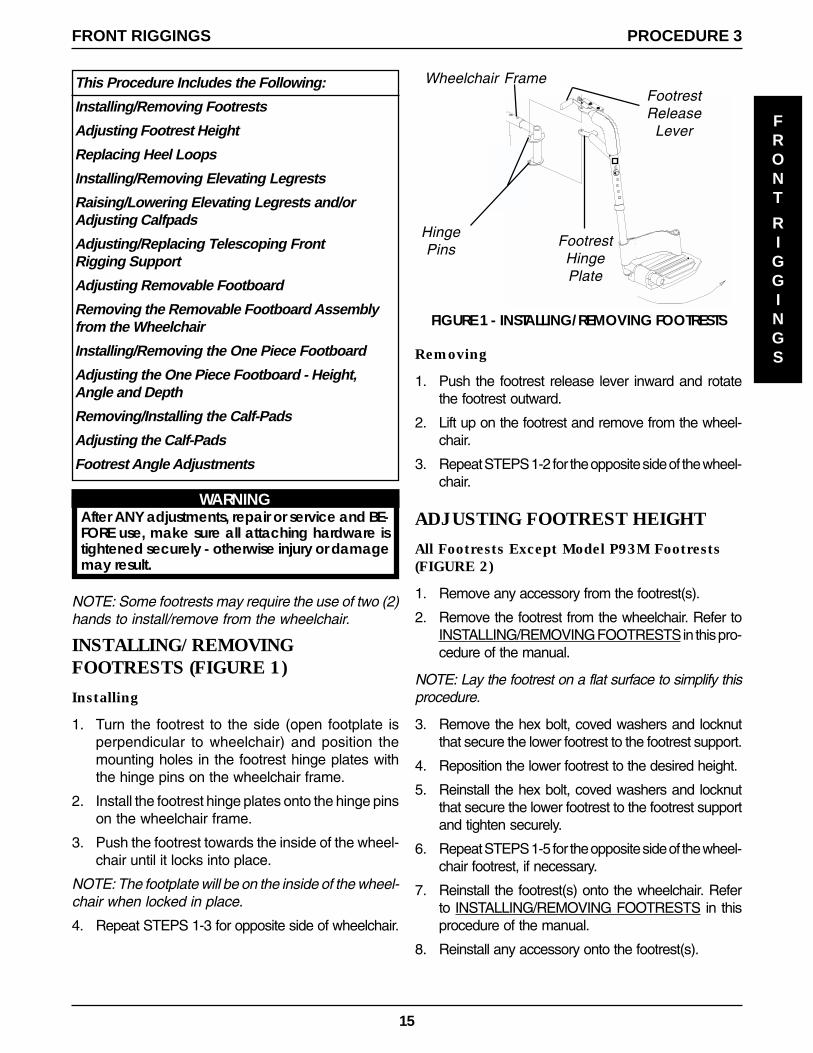
Removing
1. Push the footrest release lever inward and rotatethe footrest outward.
2. Lift up on the footrest and remove from the wheel-chair.
3. Repeat STEPS 1-2 for the opposite side of the wheel-chair.
ADJUSTING FOOTREST HEIGHT
All Footrests Except Model P93M Footrests(FIGURE 2)
1. Remove any accessory from the footrest(s).
2. Remove the footrest from the wheelchair. Refer toINSTALLING/REMOVING FOOTRESTS in this pro-cedure of the manual.
NOTE: Lay the footrest on a flat surface to simplify thisprocedure.
3. Remove the hex bolt, coved washers and locknutthat secure the lower footrest to the footrest support.
4. Reposition the lower footrest to the desired height.
5. Reinstall the hex bolt, coved washers and locknutthat secure the lower footrest to the footrest supportand tighten securely.
6. Repeat STEPS 1-5 for the opposite side of the wheel-chair footrest, if necessary.
7. Reinstall the footrest(s) onto the wheelchair. Referto INSTALLING/REMOVING FOOTRESTS in thisprocedure of the manual.
8. Reinstall any accessory onto the footrest(s).
FIGURE 1 - INSTALLING/REMOVING FOOTRESTS
FootrestHingePlate
FootrestRelease
Lever
HingePins
WARNINGAfter ANY adjustments, repair or service and BE-FORE use, make sure all attaching hardware istightened securely - otherwise injury or damagemay result.
Wheelchair Frame
NOTE: Some footrests may require the use of two (2)hands to install/remove from the wheelchair.
INSTALLING/REMOVINGFOOTRESTS (FIGURE 1)
Installing
1. Turn the footrest to the side (open footplate isperpendicular to wheelchair) and position themounting holes in the footrest hinge plates withthe hinge pins on the wheelchair frame.
2. Install the footrest hinge plates onto the hinge pinson the wheelchair frame.
3. Push the footrest towards the inside of the wheel-chair until it locks into place.
NOTE: The footplate will be on the inside of the wheel-chair when locked in place.
4. Repeat STEPS 1-3 for opposite side of wheelchair.

16
FIGURE 5- INSTALLING/REMOVING ELEVATING LEGRESTS
INSTALLING/REMOVINGELEVATING LEGRESTS (FIGURE 5)Installing
1. Turn the legrest to the side (open footplate is perpen-dicular to wheelchair) and position the mounting holesin the legrest hinge plates with the hinge pins on thewheelchair frame.
2. Install the legrest hinge plates onto the hinge pins onthe wheelchair frame.
3. Rotate legrest toward the inside of the wheelchair untilit locks in place.
NOTE: The footplate will be on the inside of the wheel-chair when locked in place.
4. Repeat STEPS 1-3 for the opposite legrest.
5. After seated in wheelchair, adjust footplate to correct heightby loosening the nut and sliding the lower footrest as-sembly up or down until desired height is achieved.
Removing
1. Push the legrest release handle toward the inside ofthe wheelchair (facing the front of the wheelchair) andswing the legrest to the outside of the wheelchair.
2. Lift up on the legrest and remove from the wheelchair.
3. Repeat STEPS 1-2 for the opposite side of the wheel-chair.
HingePins
LegrestHingePlates
Legrest Release Handle
P93M Model Footrests (FIGURE 3)
1. Loosen, but do not remove the lug bolt and locknutthat secure the lower footrest to the footrest support.
2. Reposition the lower footrest to the desired height.
3. Securely tighten the lug bolt and locknut that securethe lower footrest to the footrest support.
4. Repeat STEPS 1-3 for the opposite side of the wheel-chair footrest, if necessary.
FIGURE 3 - ADJUSTING FOOTREST HEIGHT - P93MMODEL FOOTRESTS
Phillips Bolt
Spacer
Locknut
Locknut
Heel Loop
FIGURE 4 - REPLACING HEEL LOOPS
Hex Bolt
Cover Washers
Lower Footrest
Lug Bolt
Locknut
FootrestSupport
LowerFootrest
REPLACING HEEL LOOPS (FIGURE 4)
1. Note the position of the hex bolt, coved washers andlocknut for reinstallation.
2. Remove the hex bolt, coved washers and locknutthat secure the lower footrest to the footrest support.
3. Remove the lower footrest.
4. Remove the phillips bolt, spacer and locknut that se-cure the existing heel loop to the lower footrest.
5. Slide the existing heel loop off the lower footrest.
6. Replace heel loop.
7. Reverse STEPS 1-6 to reassemble.
NOTE: When securing the heel loop to the lower footrest,tighten the phillips screw and locknut until spacer is secure.
Nut
LowerFootrestAssem-
bly
Footrest Support
WheelchairFrame
FRONT
RIGGINGS
FRONT RIGGINGSPROCEDURE 3
FIGURE 2 - ADJUSTING FOOTREST HEIGHT - ALLFOOTRESTS EXCEPT MODEL P93M FOOTRESTS
NOTE: PW93ST stylefootrest shown for clarityonly.
Footrest Support
Hex Bolt
CovedWasher
Coved Washer
Locknut
Lower Footrest

17
FRONT
RIGGINGS
PROCEDURE 3FRONT RIGGINGS
RAISING/LOWERING ELEVATINGLEGRESTS AND/OR ADJUSTINGCALFPADS (FIGURE 6)Raising/Lowering Elevating Legrests
1. Perform one (1) of the following:
RAISING - Pull back on the release leveruntil the leg is at the desiredheight.
LOWERING - Support leg with one (1) handand push release lever down-ward with other hand.
Adjusting Calfpads
1. Turn calfpad towards the outside of the wheelchair.
2. Slide the calfpad up or down until the desired posi-tion is obtained.
NOTE: If one (1) of the top two (2) calfpad adjustmentpositions is being used, the legrest will need to be raisedto avoid interference with the front stabilizers while goingover obstacles or going up and down ramps. Refer toRAISING/LOWERING ELEVATING LEGRESTS in thisprocedure of the manual.
3. Turn the calfpad towards the inside of the wheel-chair.
Release Lever
Calfpad
CalfpadRotated for
HeightAdjustment
FIGURE 6- RAISING/LOWERING ELEVATINGLEGRESTS AND/OR ADJUSTING CALFPADS
Top Two (2) CalfpadAdjustment Positions
ADJUSTING/REPLACINGTELESCOPING FRONT RIGGINGSUPPORT (FIGURE 7)
Adjusting
1. Remove the two (2) mounting screws, spacers andlocknuts that secure the telescoping front rigging sup-port to the seat frame.
2. Perform one (1) of the following:
A. Slide existing telescoping front rigging support toone (1) of three (3) depth positions.
B. Remove existing telescoping front rigging supportand install NEW telescoping front rigging support.
3. Secure telescoping front rigging at desired depth withexisting two (2) mounting screws, spacers, and lock-nuts. Securely tighten.
NOTE: The two (2) telescoping front rigging supportscan be positioned at different depths depending on theneed of the user.
Replacing
NOTE: Observe the position of the current telescopingfront rigging support before removal to ensure correctposition of new support assembly.
1. Remove the existing telescoping front rigging sup-port from the wheelchair.
2. Install the new telescoping front rigging support intothe wheelchair.
3. Adjust the telescoping front rigging support. Refer toADJUSTING TELESCOPING FRONT RIGGINGSUPPORT in this procedure of the manual.
FIGURE 7 - ADJUSTING/REPLACING TELESCOPINGFRONT RIGGING SUPPORT
Mounting Screws
Seat Frame
Spacers
Locknut TelescopingFront Tube

18
ADJUSTING REMOVABLEFOOTBOARDDepth (FIGURE 8)
1. Remove the four (4) flat head screws and barrel nutsthat secure the removable footboard to the two (2)footplate clamps.
2. Move the removable footboard to one (1) of the four(4) positions.
3. Reinstall the four (4) flat head screws and barrel nutsthat secure the removable footboard to the two (2)footplate clamps. Tighten securely.
FRONT
RIGGINGS
FRONT RIGGINGSPROCEDURE 3
FootplateClamp
RemovableFootboard
FIGURE 8 - ADJUSTING FLIP-UPREMOVABLE FOOTBOARD - DEPTH
MountingPositions
Flat Head Screws
Barrel NutBarrel Nut
Angle (FIGURE 9)
1. Loosen, but do not remove, the four (4) flat headscrews and barrel nuts that secure the removablefootboard to the two (2) footplate clamps.
NOTE: Because of the two (2) support tubes, theangle of the removable footboard can be adjusteddownward ONLY.
2. Grasp the front of the removable footboard and ro-tate it DOWNWARD until the desired angle isreached.
3. While holding the removable footboard in place,tighten the four (4) flat head screws and barrel nutssecurely.
FIGURE 9 - ADJUSTING FLIP-UP REMOVABLEFOOTBOARD - ADJUSTING FOOTBOARD ANGLE
RemovableFootboard
Barrel Nut
FlatHeadScrew
Angle Can Be AdjustedDownward ONLY
FRONT
FootplateClamp
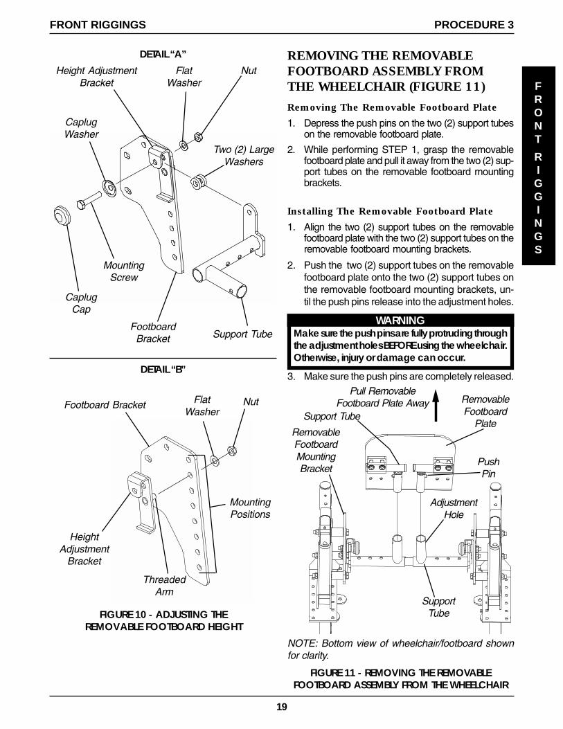
Height (FIGURE 10)
1. Remove the removable footboard plate. Refer toREMOVING THE REMOVEABLE FOOTBOARDASSEMBLY FROM THE WHEELCHAIR in this pro-cedure of the manual.
2. Remove the caplug cap.
3. Remove the mounting screw, caplug washer, flatwasher and nut that secures the two (2) large wash-ers and support tube to the height adjustmentbracket and footboard bracket. Refer to DETAIL“A”.
4. Remove the nut, flat washer and that secure thethreaded arm on the height adjustment bracket tothe footboard bracket. Refer to DETAIL “B”.
5. Move the height adjustment bracket to one (1) ofseven (7) height positions.
6. Reinstall the flat washer and nut that secures thethreaded arm on the height adjustment bracket tothe footboard bracket. Refer to DETAIL “B”.
7. Reinstall the mounting screw, caplug washer, flatwasher and nut that secures the two (2) largewashers and support tube to the height adjust-ment bracket and footboard bracket. Refer toDETAIL “A”.
8. Reinstall the caplug caps.
9. Repeat STEPS 2-8 for the opposite footboardbracket.
10. Reinstall the removable footboard plate. Refer toREMOVING THE REMOVEABLE FOOTBOARDASSEMBLY FROM THE WHEELCHAIR in this pro-cedure of the manual.
19
FRONT
RIGGINGS
FRONT RIGGINGS PROCEDURE 3
FIGURE 10 - ADJUSTING THEREMOVABLE FOOTBOARD HEIGHT
CaplugCap
MountingScrew
CaplugWasher
FlatWasher
NutHeight AdjustmentBracket
FootboardBracket
Two (2) LargeWashers
Support Tube
Footboard Bracket NutFlatWasher
MountingPositions
ThreadedArm
HeightAdjustment
Bracket
DETAIL “A”
DETAIL “B”
REMOVING THE REMOVABLEFOOTBOARD ASSEMBLY FROMTHE WHEELCHAIR (FIGURE 11)
Removing The Removable Footboard Plate
1. Depress the push pins on the two (2) support tubeson the removable footboard plate.
2. While performing STEP 1, grasp the removablefootboard plate and pull it away from the two (2) sup-port tubes on the removable footboard mountingbrackets.
Installing The Removable Footboard Plate
1. Align the two (2) support tubes on the removablefootboard plate with the two (2) support tubes on theremovable footboard mounting brackets.
2. Push the two (2) support tubes on the removablefootboard plate onto the two (2) support tubes onthe removable footboard mounting brackets, un-til the push pins release into the adjustment holes.
WARNINGMake sure the push pins are fully protruding throughthe adjustment holes BEFORE using the wheelchair.Otherwise, injury or damage can occur.
3. Make sure the push pins are completely released.
PushPin
Support Tube
RemovableFootboard
Plate
SupportTube
RemovableFootboardMountingBracket
AdjustmentHole
Pull RemovableFootboard Plate Away
FIGURE 11 - REMOVING THE REMOVABLEFOOTBOARD ASSEMBLY FROM THE WHEELCHAIR
NOTE: Bottom view of wheelchair/footboard shownfor clarity.

20
FRONT
RIGGINGS
FRONT RIGGINGSPROCEDURE 3
FIGURE 12 - INSTALLING/REMOVING THE ONEPIECE FOOTBOARD
LegrestTubeSupport
Assembly
AdjustmentLever
SeatFrame
PullRing
Detent PinAssembly
DETAIL “A”
Hex Headportion ofPull Ring
ADJUSTING THE ONE PIECEFOOTBOARD - HEIGHT, ANGLE,AND DEPTHHeight (FIGURE 13)
1. Remove the two (2) hub caps that cover the mount-ing bolt of the footboard assembly.
2. Remove the mounting bolt, locknut, two (2) caplugwashers, two (2) large washers, and two (2) spac-ers that secure the footboard assembly to thelegrest tube.
3. Raise or lower the footboard assembly to the de-sired mounting position on the legrest tube.
NOTE: Do NOT cover the warning label on the legresttube shown in FIGURE 13.
4. Secure the footboard assembly to the legrest tubein the position determined in STEP 3 with themounting bolt, two (2) cap caplug washers, two(2) large washers, two (2) spacers and locknut.Securely tighten.
5. Replace the two (2) hub caps.
FIGURE 13 - ADJUSTING THE FOOTBOARD HEIGHTCaplug Washer
Locknut
LargeWasher Caplug
Washer
MountingBolt
LargeWasher
Hub Cap
Hub CapFootboard
Spacers (Not Shown are positionedbetween the legrest tube and the
footboard assembly.)Warning Label
Angle (FIGURES 14 AND 15)
1. Loosen, DO NOT remove, the four (4) flat headscrews and barrel nuts that secure the footboardto the two (2) half clamps.
2. Rotate the two (2) half clamps on the pivot hingeuntil the desired angle is achieved.
3. Securely tighten the four (4) flat head screws tothe footboard and half clamps.
INSTALLING/REMOVING THE ONEPIECE FOOTBOARD (FIGURE 12)
Installing the One Piece Footboard
1. Pull the detent pin out from the support assembly.
2. While pulling detent pin, insert the legrest tube of the onepiece footboard assembly into the support assembly.
WARNINGBefore operating the wheelchair, ensure de-tent pin is engaged, and adjustment lever issecurely tightened, otherwise, injury and/ordamage may result.
3. Visually inspect and ensure that the detent pin isengaged.
4. Ensure pull ring is resting on the hex head portion ofthe detent pin assembly. Refer to DETAIL “A”.
5. Securely tighten the adjustment lever.
Removing the One Piece Footboard
1. Loosen, but DO NOT remove, the adjustment le-ver from the support assembly.
2. Pull the detent pin from the support assembly.
3. While pulling the detent pin, remove the one piecefootboard assembly from the support assembly.

21
Depth (FIGURE 15)
1. Remove the four (4) flat head screws and barrelnuts that secure the footboard to the two (2) halfclamps.
NOTE: The footboard depth may also be adjusted byrotating the half clamp 180o.
2. Position the footboard on the two (2) half clampsat the desired mounting position.
3. Install the four (4) flat head screws and barrel nutsthrough the footboard and two (2) half clamps.Securely Tighten.
FIGURE 15 - ADJUSTING THE FOOTBOARD ANGLE/DEPTH
FIGURE 14 - ADJUSTING THE FOOTBOARD ANGLE
Barrel Nuts
Flat HeadScrews
MountingHoles
Footboard
Heel
Half Clamp
SIDE VIEW OF 90O FOOTBOARD
Flat Head Screws(Loosen Here)
Barrel NutsPivot Hinge
Half Clamp mountingpositions
WARNINGDO NOT use thesemounting hole posi-tions with the halfclamp in this orienta-tion, otherwise injuryand/or damage mayresult.
REMOVING/INSTALLING THECALF-PADS (FIGURE 16)
NOTE: Instructions apply to removing the calf-pads.To install the calf-pads, reverse the following steps.
1. Remove the one piece footboard from the chair. Re-fer to INSTALLING/REMOVING THE ONE PIECEFOOTBOARD in this procedure of the manual.
2. Remove the two (2) phillips head screws and wash-ers that secure the calf-pad to the calf-pad bracket.
3. Repeat for other calf-pad if necessary.
Calf-Pad
Calf-Pad BracketWasher
Phillips HeadScrews
FIGURE 16 - REMOVING/INSTALLING CALF-PADS
ADJUSTING THE CALF-PADS
NOTE: Some calf-pad adjustments may require theremoval of the one piece footboard. Refer to REMOV-ING THE ONE PIECE FOOTBOARD in this procedureof the manual.
Adjusting the Calf-Pad Height (FIGURE 17)
1. Remove the calf-pads. Refer to REMOVING/IN-STALLING THE CALF-PADS in this procedure ofthe manual.
2. Remove the two (2) hub caps from the pivot bracket.
3. Remove the mounting bolt, locknut, two (2) caplugwashers and two (2) large washers that secure thepivot bracket to the legrest tube.
NOTE: DO NOT cover the warning label on the legresttube shown in FIGURE 17.
4. Slide the calf assembly up or down to the desiredposition on the legrest tube.
5. Secure pivot bracket to the legrest tube with themounting bolt, (2) caplug washers and two (2) largewashers and locknut. Securely tighten.
6. Replace the two (2) hub caps over the caplug wash-ers.
7. If necessary, replace the one piece footboard. Re-fer to INSTALLING THE ONE PIECE FOOTBOARDin this procedure of the manual.
FRONT
RIGGINGS
FRONT RIGGINGS PROCEDURE 3
22
NOTE: Calf-pads not shown for clarity.
CaplugWasher
Locknut
Large WasherCaplugWasher
MountingBolt
LargeWasher
Hub Cap
Hub Cap
Footboard
FIGURE 17 - ADJUSTING THE CALF-PAD HEIGHT
Pivot Bracket
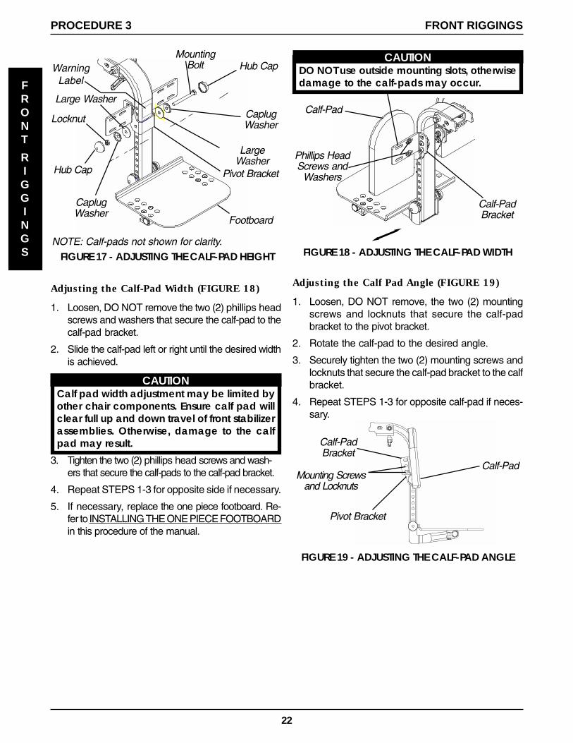
Adjusting the Calf-Pad Width (FIGURE 18)
1. Loosen, DO NOT remove the two (2) phillips headscrews and washers that secure the calf-pad to thecalf-pad bracket.
2. Slide the calf-pad left or right until the desired widthis achieved.
CAUTIONCalf pad width adjustment may be limited byother chair components. Ensure calf pad willclear full up and down travel of front stabilizerassemblies. Otherwise, damage to the calfpad may result.
3. Tighten the two (2) phillips head screws and wash-ers that secure the calf-pads to the calf-pad bracket.
4. Repeat STEPS 1-3 for opposite side if necessary.
5. If necessary, replace the one piece footboard. Re-fer to INSTALLING THE ONE PIECE FOOTBOARDin this procedure of the manual.
FIGURE 18 - ADJUSTING THE CALF-PAD WIDTH
Phillips HeadScrews and
Washers
Calf-Pad
Calf-PadBracket
CAUTIONDO NOT use outside mounting slots, otherwisedamage to the calf-pads may occur.
Adjusting the Calf Pad Angle (FIGURE 19)
1. Loosen, DO NOT remove, the two (2) mountingscrews and locknuts that secure the calf-padbracket to the pivot bracket.
2. Rotate the calf-pad to the desired angle.
3. Securely tighten the two (2) mounting screws andlocknuts that secure the calf-pad bracket to the calfbracket.
4. Repeat STEPS 1-3 for opposite calf-pad if neces-sary.
WarningLabel
Mounting Screwsand Locknuts
Calf-PadBracket
Pivot Bracket
Calf-Pad
FIGURE 19 - ADJUSTING THE CALF-PAD ANGLE
FRONT
RIGGINGS
FRONT RIGGINGSPROCEDURE 3

23
Adjusting the Calf-Pad Depth
NOTE: The calf-pad depth can be adjusted in one (1) orboth of the following manners:
1. The pivot bracket can be mounted in a FOR-WARD or REARWARD position. For further calf-pad depth adjustment, the pivot bracket can beremoved. See Note 2A.
2. The calf-pad bracket (which is mounted to thepivot bracket) can be mounted in a FORWARDor REARWARD position.
A. If the pivot bracket is removed, the calf-padbrackets are mounted directly to the legresttube, this will be referred to as the DIRECTMOUNT METHOD in this instruction sheet.
1. Perform one (1) of the following:
A. If pivot bracket method is desired, proceed to AD-JUSTING THE CALF-PAD DEPTH USING THEPIVOT BRACKET in this procedure of the manual.
B. If direct mount method is desired, proceed toADJUSTING THE CALF-PAD DEPTH USINGTHE DIRECT MOUNT METHOD in this proce-dure of the manual.
ADJUSTING THE CALF-PAD DEPTH USINGTHE PIVOT BRACKET (FIGURES 20 AND 21).1. Remove the calf-pads. Refer to REMOVING/INSTALL-
ING THE CALF PADS in this procedure of the manual.
2. Remove the center mounting screw, nylon spacer,small washer, and locknut that secure the calf-padmounting bracket to the pivot bracket (FIGURE 21).
3. Remove the other mounting screw, small washerand locknut that secure the calf-pad mountingbracket to the pivot bracket (FIGURE 21).
4. Repeat STEPS 1-3 for other calf-pad bracket.
LegrestTube
LargeWashers
CaplugWasher
MountingBolt
HubCapCaplug
Washer
LocknutHub Cap
PivotBracket
5. Perform one (1) of the following:
A. If changing the mounting orientation of the pivotbracket, perform the following steps (FIGURE 20):
� Remove the two (2) hub caps from the pivotbracket.
� Remove the mounting bolt, two (2) caplugwashers, two (2) large washers and locknutthat secure the pivot bracket to the legrest tube.
� Reposition the pivot bracket on the legrest tubein the FORWARD or REARWARD position.
� Secure the pivot bracket to the legrest tube inthe position determined above with the mount-ing bolt, two (2) caplug washer, two (2) largewashers and locknut. Securely Tighten.
� Reinstall the two (2) hub caps onto the mount-ing bolt and locknut.
B. If NOT changing the mounting orientation of thepivot bracket and only changing the calf padmounting brackets, proceed to STEP 6.
6. Position calf-pad mounting bracket on pivot bracketin the desired orientation (FIGURE 21).
7. Secure the calf-pad mounting bracket to the pivotbracket with the EXISTING center mounting screw,nylon spacer, small washer, and locknut in the ori-entation determined in STEP 6. Securely Tighten(FIGURE 21).
8. Secure the calf-pad bracket to the pivot bracketwith the other mounting screw, small washer andlocknut in the orientation determined in STEP 6.Securely tighten (FIGURE 21).
9. Install the calf-pads. Refer to REMOVING/IN-STALLING THE CALF-PADS in this procedure ofthe manual.
FIGURE 20 - ADJUSTING THE CALF-PAD DEPTHUSING THE PIVOT BRACKET - CHANGING THE
MOUNTING ORIENTATION OF THE PIVOT BRACKET
FRONT
RIGGINGS
FRONT RIGGINGS PROCEDURE 3

24
PIVOT BRACKET IN REARWARD MOUNT POSITION
CALF-PAD IN FORWARD MOUNT POSITION CALF-PAD IN REARWARD MOUNT POSITION
LegrestTube
PIVOT BRACKET IN FORWARD MOUNT POSITIONCALF-PAD IN FORWARD MOUNT POSITION CALF-PAD IN REARWARD MOUNT POSITION
CAUTIONDO NOT use this mount-ing position, otherwisedamage to the legrestassembly and or wheel-chair will result.
MountingScrews
Calf-PadBracket
SmallWashers
Legrest Tube
PivotBracket
NylonSpacer
Locknuts
Calf-PadBracket
Pivot Bracket
NOTE: Mounting hard-ware is in reverse orienta-tion of forward mount.
MountingScrew
Calf-PadBracket
SmallWasher
Locknut
LegrestTube
PivotBracket
Calf-Pad
LegrestTube
FIGURE 21 - ADJUSTING THE CALF-PAD DEPTH - COMPONENT AND HARDWARE ORIENTATION
SIDE VIEW
LegrestTube
Calf-Pad
SIDE VIEW
LegrestTube
Calf-Pad
CenterMounting
Screw
SIDE VIEW
LegrestTube
Calf-Pad
NylonSpacer
CenterMounting
Screw
FRONT
RIGGINGS
FRONT RIGGINGSPROCEDURE 3

25
CALF-PAD BRACKETS IN FORWARD MOUNTPOSITION
5/16-24 x 3-inchMounting ScrewsCalf-Pad
Bracket
Calf-PadBracket
Washer
Washer
Locknuts
FIGURE 22 - ADJUSTING THE CALF-PAD DEPTH - DIRECT MOUNT METHOD
SIDE VIEW
LegrestTube
Calf-Pad
SIDE VIEW
LegrestTube
Calf-Pad
CALF PAD-BRACKETS IN REVERSE MOUNT POSITION
LegrestTube
LocknutsSmall
Washers
Large Washer
Mounting Bolt
CenterMounting
Screw
Hub Cap
Calf-Pad Bracket
Mounting Screw
Nylon Spacer
Large Washer
Caplug Washer
Locknut
Hub Cap
Caplug Washer
Calf-PadBracket
PivotBracket
ADJUSTING THE CALF-PAD DEPTH USINGTHE DIRECT MOUNT METHOD (FIGURE 22).1. Remove the calf-pads. Refer to REMOVING/INSTALL-
ING THE CALF PADS in this procedure of the manual.
2. Remove the center mounting screw, nylon spacer,small washer, and locknut that secure the calf-padbracket to the pivot bracket.
3. Remove the other mounting screw and locknut thatsecure the calf-pad bracket to the pivot bracket.
4. Perform STEPS 1-3 for other calf-pad mountingbracket.
5. Remove the two (2) hub caps from the pivotbracket.
6. Remove the mounting bolt, two (2) caplug wash-ers, two (2) large washers and locknut that se-cure the pivot bracket to the legrest tube.
NOTE: Save the pivot bracket and attaching mount-ing hardware from STEPS 2-6 for future use. Securelytighten.
7. Position the calf-pad brackets on the legrest tubein the desired orientation. Refer to FIGURE 22.
8. Secure the calf-pad brackets to the legrest tube withthe two (2) 5/16-24 x 3-inch long mounting screws,washers and locknuts in the orientation determinedin STEP 7.
9. Install the calf-pads. Refer to REMOVING/INSTALL-ING THE CALF PADS in this procedure of the manual.
FRONT
RIGGINGS
FRONT RIGGINGS PROCEDURE 3

26
FOOTREST ANGLE ADJUSTMENTS(FIGURE 23)
Footrest Angle Adjustment Relative to theVertical Position of the Front Shroud
NOTE: The angle of the footrest relative to the verticalposition of the front shroud can be increased or de-creased by adjusting both cams located at the top of thefootrest support.
1. Loosen the mounting screw and locknut that se-cure the cams to the upper mounting bracket. Re-fer to DETAIL “B”.
NOTE: Both cams MUST be rotated to the same po-sition to keep the footrest square to the base.
2. Rotate both cams either direction until footrest isat desired angle. Refer to DETAIL “C” and “D”
3. Securely tighten mounting screw and locknut.
FIGURE 23 - FOOTREST ANGLE ADJUSTMENTS
DETAIL “E” - TOP VIEW OF FOOTREST
DETAIL “D” - SIDE VIEW OF FOOTRESTDETAIL “B”
Right Cam Left Cam
FootrestHorizontalPosition
of Front Shroud
Direction ofFootrestRotation
DETAIL “C”
MountingScrew
Locknut
Cams
UpperMountingBracket
Vertical Positionof Front Shroud
NOTE: Angle isincreased ordecreaseddepending
on direction ofcam rotation
Direction ofFootrestRotation
Footrest Angle Adjustment Relative to theHorizontal Position of the Front Shroud
NOTE: The footrest is factory set to be centered be-tween the stabilizer assemblies. During shipping anddaily use the footrest can become shifted to one sideor the other. This procedure is to center the footrestso it does not interfere with stabilizer assemblies
1. Loosen the mounting screw and locknut that se-cure the cams to the upper support bracket. Re-fer to DETAIL “B”.
2. While holding either cam in position, turn the othercam in one direction. This will rotate the footrest.If the footrest is not rotating towards the center,turn the cam in the opposite direction. Refer toDETAIL “E”.
3. Securely tighten the mounting screw and locknutthat secure the cams to the upper support bracket.Refer to DETAIL “B”.
Cam
FRONT
RIGGINGS
FRONT RIGGINGSPROCEDURE 3

27
This Procedure Includes the Following:
Installing/Removing Flip Back Armrests
Adjusting Flip Back Armrests
Adjusting Captain's Seat Armrests
INSTALLING/REMOVING FLIP BACKARMRESTS (FIGURE 1)
WARNINGMake sure the flip back armrest release andheight adjustment levers are in the locked posi-tion before using the wheelchair.
NOTE: Flip back armrest release lever must be in un-locked position when placing armrest into the arm sock-ets.
Installing
1. Slide the flip back armrest into the arm sockets on thewheelchair frame.
2. Install the quick release pin through the rear arm socketand flip back armrest.
3. Lock flip back armrest by pressing flip back armrestrelease lever into the DOWN (VERTICAL) position.
4. Lift up on flip back armrest to make sure the armrestis locked in place.
5. Repeat STEPS 1-4 for opposite flip back armrest.
Removing
1. Unlock flip back armrest by pulling flip back armrestrelease lever into the UP (HORIZONTAL) position.
2. Remove the quick release pin that secures the flipback armrest to the wheelchair frame.
3. Pull up on the flip back armrest and remove the arm-rest from the arm sockets.
4. Repeat STEPS 1-3 for the opposite flip back arm-rest, if necessary.
ADJUSTING FLIP BACK ARMRESTS(FIGURE 2)Positioning Flip Back Armrests for UserTransfer
1. Unlock the flip back armrest by pulling the armrestrelease lever into the UP (HORIZONTAL) position.
2. Pull up on the flip back armrest and remove the arm-rest from the front arm socket.
3. Continue to pull up on the flip back armrest until thearmrest is out of the way.
4. Repeat STEPS 1-3 for opposite flip back armrest, ifnecessary.
WARNINGAfter ANY adjustments, repair or service and BE-FORE use, make sure all attaching hardware istightened securely - otherwise injury or damagemay result.
PROCEDURE 4ARMS
ARMS
FIGURE 1 - INSTALLING/REMOVING FLIP BACKARMRESTS
Flip BackArmrest
LOCKED (DOWN -VERTICAL)
UNLOCKED (UP-HORIZONTAL)
Flip BackArmrestRelease
Lever
RearArm
Socket
SeatFrame
QuickRelease Pin
Front ArmSocket
FIGURE 2 - ADJUSTING FLIP BACK ARMRESTS
LOCKED (DOWN -VERTICAL)Height
AdjustmentLever
Flip BackArmrest
Release Lever
Flip BackArmrest
UNLOCKED (UP-HORIZONTAL)
Front ArmSocket

28
Positioning Flip Back Armrests for Use
1. Make sure the flip back armrest release lever is inthe UP (HORIZONTAL) position.
2. Install the flip back armrest into the front arm socket.
3. Lock flip back armrest by pressing flip back armrestrelease lever into the DOWN (VERTICAL) position.
4. Lift up on flip back armrest to make sure the armrestis locked in place.
5. Repeat STEPS 1-4 for opposite flip back armrest, ifnecessary.
Adjusting
1. Unlock top of flip back armrest by pulling height ad-justment lever into the UP (HORIZONTAL) position.
2. Adjust top of the flip back armrest to the desiredheight.
3. Lock top of flip back armrest by pushing height ad-justment lever into the DOWN (VERTICAL) position.
4. Lift up on flip back armrest to make sure the armrestis locked in place.
5. Repeat STEPS 1-4 for opposite flip back armrest, ifnecessary.
ADJUSTING CAPTAIN'S SEATARMRESTSAngle (FIGURE 3)
1. Lift-up the armrest.
2. Loosen the jam nut.
3. Adjust the socket screw up or down to the desiredarm angle position.
4. Tighten the jam nut.
5. To determine the same angle for the opposite arm-rest, count the exposed threads after the jam nuthas been tightened.
6. Repeat STEPS 1-5 for opposite armrest, if neces-sary.
Socket ScrewArmrest
FIGURE 3 - ADJUSTING CAPTAIN'S SEAT ARMRESTS -ANGLE
Jam Nut
Count Exposed Threads
FIGURE 4 - ADJUSTING CAPTAIN'S SEAT ARMRESTS -HEIGHT
Socket Screw
Seat FrameAssembly
HeightAdjustment
Holes
Height (FIGURE 4)
1. Remove the socket screw that secures the armrestto the seat frame assembly.
2. Adjust the armrest to one (1) of four (4) positions.
3. Reinstall the socket screw that secures the armrestto the seat frame assembly and tighten securely.
Armrest
ARMS
ARMSPROCEDURE 4

29
ADJUSTING CAPTAIN'S SEAT(FIGURE 1)
Low Back Captain's Seats
1. Lift up on the release handle and move the back tothe desired position.
High Back Captain's Seats
ANGLE.WARNING
HIGH BACK CAPTAIN'S SEATS ONLY - NEVER oper-ate the wheelchair while in any recline position over114o RELATIVE TO THE SEAT FRAME. If the limit switchdoes not stop the wheelchair from operating in arecline position greater than 114o RELATIVE TO THESEAT FRAME, do not operate the wheelchair. Havethe wheelchair serviced by a qualified technician.
1. Lift up on the release handle and move the back tothe desired position.
2. Check the angle of the back RELATIVE TO THE SEATFRAME.
3. If necessary, have the limit switch adjusted. Contactan authorized Invacare dealer or qualified technician.
LUMBAR.1. Rotate the knob on the side of the high back Captain's
Seat COUNTERCLOCKWISE until the desired sup-port is obtained.
NOTE: The knob only rotates COUNTERCLOCKWISE.
This Procedure Includes the Following:
Adjusting Captain's Seat
Replacing Seat Positioning Strap
FIGURE 1 - ADJUSTING CAPTAIN'S SEAT
PROCEDURE 5CAPTAIN'S SEAT/POSITIONING STRAP
POSITIONING
STRAP
CAPTAINS
SEAT
ReleaseHandle
Knob -HighBack
Captain'sSeatsOnly
REPLACING SEAT POSITIONINGSTRAP
Adjustable Seat Back Angle Model (FIGURE 2)
1. Remove the seat cushion from the seat pan.
2. Move the flip back armrests out of the way. Refer toADJUSTING FLIP BACK ARMRESTS in PROCE-DURE 4 of this manual.
3. Remove the two (2) mounting screws, quick releasepin tabs, spacers, and locknuts that secure the seatpan and seat positioning straps to the seat frame.
4. Remove the two (2) halves of the seat positioningstrap from the rear seat frame.
NOTE: Quick release pin tabs are positioned underneaththe seat positioning strap.
5. Reposition the two (2) NEW seat positioning straphalves underneath seat rails.
6. Reinstall the two (2) mounting screws, quick releasepin tabs, spacers, and locknuts that secure the seatpan and seat positioning straps to the seat frameand torque to 75-inch pounds.
7. Reinstall the seat cushion onto the seat pan.
FIGURE 2 - REPLACING SEAT POSITIONING STRAP
SeatPanSeat
PositioningStrap
Locknut
MountingScrew
QuickReleasePin Tab
Spacer
Front ofSeat Frame
Rear ofSeat Frame
Seat Rail

30
This Procedure Includes the Following:
Preparing MKIV Joystick for Use
Repositioning MKIV Joystick
Repositioning Battery Charger Connector
Fuse Replacement
PREPARING MKIV JOYSTICK FORUSE (FIGURE 1)NOTE: The MKIV joystick is factory installed on the right sideof the wheelchair. To reposition the MKIV joystick onto the leftside of the wheelchair, perform one (1) of the following: AD-JUSTABLE SEAT BACK ANGLE/RECLINER SEAT - RE-POSITIONING MKIV JOYSTICK in this procedure of themanual or CAPTAIN'S SEAT MODEL WHEELCHAIRS -have the joystick repositioned by a qualified technician.
1. Turn the lever on the adjustment lock to release theadjustment lock from joystick mounting tube.
2. Slide joystick mounting tube to the desired position.
3. Turn the lever on the adjustment lock to secure theadjustment lock to the joystick mounting tube.
JoystickMountingTube
FIGURE 1 - PREPARING MKIV JOYSTICK FOR USE
MKIV Joystick
AdjustmentLock
Threaded Hole Half Clamp
Joystick Mounting Tube
Hex Screws
Joystick Mounting Bracket
Adjustment Lock
Arm Tube
Joystick
Opened Hole Half Clamp
FIGURE 2 - REPOSITIONING MKIV JOYSTICK -ADJUSTABLE SEAT BACK ANGLE/RECLINER SEAT
MODELS
WARNINGAfter ANY adjustments, repair or service and BEFOREuse, make sure all attaching hardware is tightenedsecurely - otherwise injury or damage may result.
ELECTRONICS
PROCEDURE 6
REPOSITIONING MKIV JOYSTICKAdjustable Seat Back Angle/Recliner SeatModels (FIGURE 2)
1. Turn the lever on the adjustment lock to release theadjustment lock from joystick mounting tube (tube).
2. Remove the joystick from the wheelchair.
3. Remove the three (3) hex screws that secure joystickmounting bracket (bracket), the threaded hole halfclamp and the opened hole half clamp to the arm tube.
4. Reposition the threaded hole half clamp and openedhole half clamp on the opposite arm tube. Make surethreaded hole half clamp is on the inside of arm tube.
5. While holding the two (2) half clamps, install the fronthex screw into the two (2) half clamps. Securely tighten.
6. Line up mounting holes of the joystick mounting bracketwith the mounting holes in the two (2) half clamps.
7. Secure the joystick mounting bracket to the two (2) halfclamps with the remaining two (2) hex screws.
8. Slide tube through the bracket to the desired position.
9. Slide adjustment lock over end of tube and secure ad-justment lock to tube by turning lever on adjustment lock.
NOTE: If adjustment lock does not fit over tube, rotate 180o.
31
ELECTRONICS
PROCEDURE 6ELECTRONICS
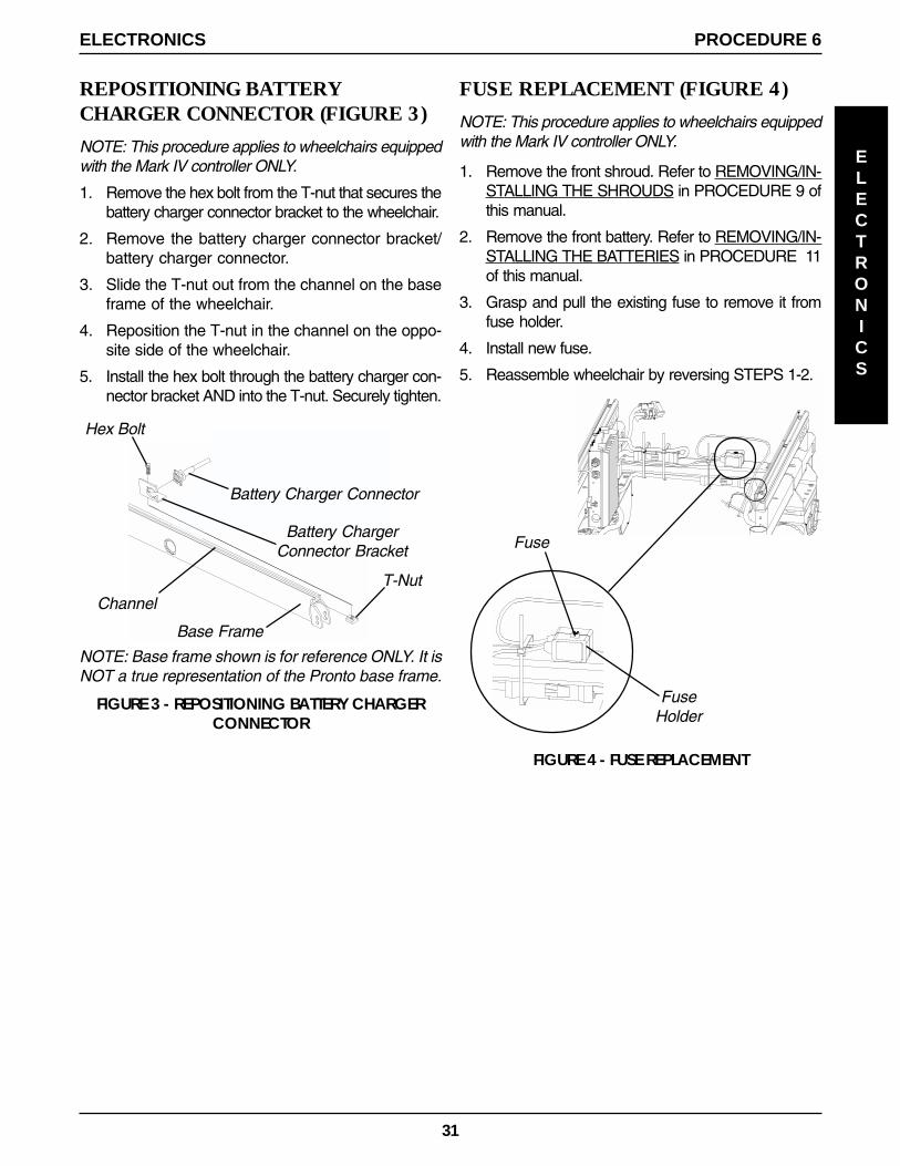
REPOSITIONING BATTERYCHARGER CONNECTOR (FIGURE 3)
NOTE: This procedure applies to wheelchairs equippedwith the Mark IV controller ONLY.
1. Remove the hex bolt from the T-nut that secures thebattery charger connector bracket to the wheelchair.
2. Remove the battery charger connector bracket/battery charger connector.
3. Slide the T-nut out from the channel on the baseframe of the wheelchair.
4. Reposition the T-nut in the channel on the oppo-site side of the wheelchair.
5. Install the hex bolt through the battery charger con-nector bracket AND into the T-nut. Securely tighten.
FIGURE 3 - REPOSITIONING BATTERY CHARGERCONNECTOR
FIGURE 4 - FUSE REPLACEMENT
Fuse
FuseHolder
Battery Charger Connector
Base Frame
Hex Bolt
FUSE REPLACEMENT (FIGURE 4)
NOTE: This procedure applies to wheelchairs equippedwith the Mark IV controller ONLY.
1. Remove the front shroud. Refer to REMOVING/IN-STALLING THE SHROUDS in PROCEDURE 9 ofthis manual.
2. Remove the front battery. Refer to REMOVING/IN-STALLING THE BATTERIES in PROCEDURE 11of this manual.
3. Grasp and pull the existing fuse to remove it fromfuse holder.
4. Install new fuse.
5. Reassemble wheelchair by reversing STEPS 1-2.
Channel
Battery ChargerConnector Bracket
T-Nut
NOTE: Base frame shown is for reference ONLY. It isNOT a true representation of the Pronto base frame.

32
This Procedure Includes the Following:
Replacing Battery Box Retaining Strap
WARNINGAfter ANY adjustments, repair or service and BEFOREuse, make sure all attaching hardware is tightenedsecurely - otherwise injury or damage may result.
RETAINING
STRAP
PROCEDURE 7 RETAINING STRAP
REPLACING BATTERY BOXRETAINING STRAP (FIGURE 1)
1. If necessary, remove the front and rear shrouds. Re-fer to REMOVING/INSTALLING SHROUDS in PRO-CEDURE 9 of this manual.
2. Remove the battery boxes from the wheelchair. Re-fer to INSTALLING/REMOVING BATTERY BOXESin PROCEDURE 11 of this manual.
3. Feed the EXISTING battery box retaining strapthrough the male end of the retaining strap clip(DETAIL "A").
4. Feed the EXISTING battery box retaining strap throughthe slot on the OUTSIDE of the battery box tray.
5. Feed the EXISTING battery box retaining strap throughthe slot on the INSIDE of the battery box tray.
6. Feed the EXISTING battery box retaining strapthrough the slot at the TOP of the bracket on thebattery box tray.
7. Remove the EXISTING battery box retaining strap.
8. Feed the NEW battery box retaining strap through theslot at the TOP of the bracket on the battery box tray.
9. Feed the NEW battery box retaining strap throughthe slot on the INSIDE of the battery box tray.
NOTE: The NEW battery box retaining strap shouldpass UNDER the battery box tray.
10. Feed the NEW battery box retaining strap throughthe slot on the OUTSIDE of the battery box tray.
WARNINGThe retaining strap MUST be fed through the maleend of the battery box retaining strap clip as shownin DETAIL "A" of FIGURE 1. Otherwise, batteries willnot be secured in place properly resulting in injuryto the user and/or damage to the wheelchair.
11. Feed the NEW battery box retaining strap throughthe male end of the retaining strap clip (DETAIL "A").
NOTE: Strap should have 3/4-inch length minimumbeyond buckle.
12. Install the battery boxes onto the wheelchair. Refer toINSTALLING/REMOVING BATTERY BOXES in PRO-CEDURE 11 of this manual.
WARNINGThe Battery Box Retaining Strap MUST be fastenedsecurely and adjusted properly to hold batteryboxes in place before using the wheelchair. Oth-erwise, injury to the user and/or damage to thewheelchair may occur.
13. If necessary, install the front and rear shrouds. Referto REMOVING/INSTALLING SHROUDS in PROCE-DURE 9 of this manual.
FIGURE 1 - REPLACING BATTERY BOX RETAINING STRAP
BatteryBox Tray
Top Slot (STEP 6, STEP 8)
Bracket
Inside Slot(STEP 5,STEP 9)
Outside Slot (STEP 4, STEP 10)
Retaining Strap Passes Under Battery Tray
Male End ofRetaining StrapClip (STEP 3,
STEP 11)
3/4-inch Minimum
NOTE: Tray shown by itself for clarity. There is no need to remove the tray from the wheelchair if the retainingstrap is being replaced.
DETAIL "A"
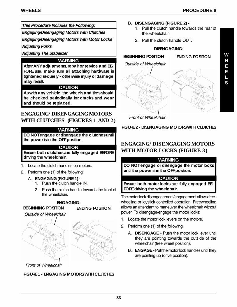
33
WHEELS
PROCEDURE 8WHEELS
ENGAGING/DISENGAGING MOTORSWITH CLUTCHES (FIGURES 1 AND 2)
WARNINGDO NOT engage or disengage the clutches untilthe power is in the OFF position.
CAUTIONEnsure both clutches are fully engaged BEFOREdriving the wheelchair.
1. Locate the clutch handles on motors.
2. Perform one (1) of the following:
A. ENGAGING (FIGURE 1) -1. Push the clutch handle IN.
2. Push the clutch handle towards the front ofthe wheelchair.
ENGAGING/DISENGAGING MOTORSWITH MOTOR LOCKS (FIGURE 3)
WARNINGDO NOT engage or disengage the motor locksuntil the power is in the OFF position.
CAUTIONEnsure both motor locks are fully engaged BE-FORE driving the wheelchair.
The motor lock disengagement/engagement allows free-wheeling or joystick controlled operation. Freewheelingallows an attendant to maneuver the wheelchair withoutpower. To disengage/engage the motor locks:
1. Locate the motor lock levers on the motors.
2. Perform one (1) of the following:
A. DISENGAGE - Push the motor lock lever untilthey are pointing towards the outside of thewheelchair (free wheel position).
B. ENGAGE - Pull the motor lock handles until theyare pointing up (drive position).
This Procedure Includes the Following:
Engaging/Disengaging Motors with Clutches
Engaging/Disengaging Motors with Motor Locks
Adjusting Forks
Adjusting The Stabalizer
FIGURE 2 - DISENGAGING MOTORS WITH CLUTCHES
BEGINNING POSITION ENDING POSITIONENGAGING:
BEGINNING POSITION ENDING POSITION
DISENGAGING:
Front of Wheelchair
Outside of Wheelchair
Outside of Wheelchair
Front of Wheelchair
B. DISENGAGING (FIGURE 2) -1. Pull the clutch handle towards the rear of
the wheelchair.
2. Pull the clutch handle OUT.
FIGURE 1 - ENGAGING MOTORS WITH CLUTCHES
WARNINGAfter ANY adjustments, repair or service and BE-FORE use, make sure all attaching hardware istightened securely - otherwise injury or damagemay result.
CAUTIONAs with any vehicle, the wheels and tires shouldbe checked periodically for cracks and wearand should be replaced.

34
FIGURE 3 - ENGAGING/DISENGAGING MOTORSWITH MOTOR LOCKS
TowardsOutside ofWheelchair
Motor Locks DISENGAGED(Free Wheel Position)
Motor Locks ENGAGED(Drive Position)
Dust Cover
Locknut
Nylon Washer
Fork
ADJUSTING FORKS (FIGURE 4)1. Remove the dust cover from the caster headtube.
2. To properly tighten caster journal system and guardagainst flutter, perform the following check:A. Tip back the wheelchair to floor.B. Pivot both forks and casters to top of their arc
simultaneously.C. Let casters drop to bottom of arc (wheels should
swing once to one-side, then immediately rest ina straight downward position).
D. Adjust locknuts according to freedom of casterswing.
3. Test wheelchair for maneuverability.
4. Readjust locknuts if necessary, and repeat STEPS1-3 until correct.
5. Snap dust cover into the caster headtube.
FIGURE 4 - ADJUSTING FORKS
Caster
CasterHeadtube
PROCEDURE 8 WHEELS
WHEELS
ADJUSTING THE STABILIZER(FIGURE 5)
1. With the batteries and the user in the wheelchair, graspthe swing arm and pull up. Clearance between the sta-bilizer wheel and the surface should be 1/8-inch orgreater. If the clearance is less than 1/8-inch contactInvacare Dealer for service. See DETAIL "A".
Additional Adjustments for User Preference(DETAIL "B")
1. Rotating the locknut that is located on top of the lowerspring provides one (1) of the following:
A. Rotating the locknut CLOCKWISE - providesmore resistance of the stabilizer when stopping.
B. Rotating the locknut COUNTER-CLOCKWISE- provides less resistance of the stabilizer whenstopping.
Clearance should be 1/8-inch or greater
Ground/Floor
StabilizerWheel
Stabilizer
Locknut
FIGURE 5 - ADJUSTING THE STABILIZER
LowerSpring
DETAIL "A"
DETAIL "B"

35
FIGURE 1 - REMOVING/INSTALLING SHROUDS
Front Shroud
1/4-Turn Bolts
Rear Shroud
NOTE: Side shrouds are exploded away for clarity.There is no need to remove side shrouds.
SHROUDS
PROCEDURE 9SHROUDS
This Procedure Includes the Following:
Removing/Installing Shrouds
REMOVING/INSTALLING SHROUDS(FIGURE 1)
Removing Front Shroud
1. Turn the two (2) 1/4-turn bolts that secure front shroudto the two (2) side shrouds COUNTERCLOCKWISE.
2. Remove the front shroud from the wheelchair.
Installing Front Shroud
1. Position the two (2) 1/4-turn bolts with the two (2)mounting holes in the side shrouds.
2. Install the front shroud onto the two (2) side shrouds.
3. Turn the two (2) 1/4-turn bolts that secure the frontshroud to the two (2) side shrouds CLOCKWISE.
WARNINGAfter ANY adjustments, repair or service and BE-FORE use, make sure all attaching hardware istightened securely - otherwise injury or damagemay result.
Removing Rear Shroud and Rear StorageCompartment
NOTE: The rear storage compartment is available onwheelchairs NOT equipped with weight shift basic tilt only.
1. Lift up on rear shroud and remove from wheelchair.
2. Turn the two (2) 1/4-turn bolts that secure the rearstorage compartment to the wheelchair frame COUN-TERCLOCKWISE.
3. Remove rear storage compartment from wheelchair.
Installing Rear Shroud and Rear StorageCompartment
1. Position the two (2) 1/4-turn bolts with the two (2)mounting holes in the wheelchair frame.
2. Install rear storage compartment onto chair frame.
3. Turn two (2) 1/4-turn bolts that secure the rear stor-age compartment to the wheelchair frame CLOCK-WISE.
4. Position rear shroud on the two (2) side shrouds andslide towards the front of the wheelchair until it stops.
5. Press down on the rear shroud until the two (2) clipssecure the rear shroud to the two (2) side shrouds.
WheelchairFrame
Rear StorageCompartment

36
PROCEDURE 10 RECLINER
REPLACING BACK OR HEADRESTUPHOLSTERY (FIGURE 2)
Replacing Back Upholstery
1. Remove the ten (10) or twelve (12) mounting screws(depending on back height) that secure the backupholstery to the back canes.
2. Remove existing back upholstery from back canes.
3. Install the new back upholstery onto the back canes.
4. Install the ten (10) or twelve (12) mounting screws(depending on back height) that secure the backupholstery to the recliner back canes.
5. Adjust the back upholstery to the desired tautness.Refer to ADJUSTING BACK OR HEADREST UP-HOLSTERY in this procedure of the manual.
NOTE: Changing the back upholstery height must be per-formed by a qualified technician.
Replacing Headrest Upholstery
1. Remove the six (6) mounting screws that secure theheadrest upholstery to the headrest extensions.
2. Remove the existing headrest upholstery from theheadrest extensions.
3. Install the new headrest upholstery onto the head-rest extensions.
4. Install the six (6) mounting screws that secure theheadrest upholstery to the headrest extensions.
This Procedure Includes the Following:
Recliner Operation
Replacing Back or Headrest Upholstery
Adjusting Back or Headrest Upholstery
RECLINER OPERATION (FIGURE 1)
WARNINGALWAYS make sure that the wheelchair is stableBEFORE using the recliner option.
NEVER operate the wheelchair while in any reclineposition over 105o RELATIVE TO THE SEAT FRAME. Ifthe limit switch does not stop the wheelchair fromoperating in a recline position greater than 105o
RELATIVE TO THE SEAT FRAME, do not operate thewheelchair. Have the limit switch adjusted by aqualified technician.Both gas cylinders MUST be operational and ad-justed properly BEFORE using the recliner. DO NOToperate the recliner option if only one (1) of thegas cylinders is operational or adjusted properly.
TO HEALTHCARE PROFESSIONALS/ASSISTANTS:
Make sure the occupant of the wheelchair is prop-erly positioned.When returning the occupant of the wheelchairto the full upright position, more body strength willbe required for approximately the last twenty (20)degrees of incline (reverse recline). Make sure touse proper body mechanics (use your legs) or seekassistance if necessary to avoid injury.
1. Make sure the wheelchair is on a level surface.
2. Inform the occupant of the wheelchair that the wheel-chair is about to be reclined.
3. Stand behind the wheelchair and grasp both back canesfirmly.
4. Pull up on the handles of the recliner cable assembliesto release the gas cylinders.
5. SLOWLY, push down on the back canes while squeez-ing the handles of the recliner cable assemblies in acontinuous motion.
6. When the back reaches the desired angle, SLOWLYlet go of the handles of the recliner cable assemblies.
7. To return the back to the full upright position, reversethe above steps keeping in mind proper body me-chanics.
FIGURE 1 - RECLINER OPERATION
Handle
RECLINER

37
FIGURE 2 - REPLACING BACK ORHEADREST UPHOLSTERY
MountingScrews
BackCane
HeadrestExtension
Headrest Upholstery
BackUpholstery
ADJUSTING BACK OR HEADRESTUPHOLSTERY (FIGURE 3)
1. Rotate the spreader bar either:
A. COUNTERCLOCKWISE (away from back up-holstery) to LOOSEN back/headrest upholstery
ORB. CLOCKWISE (towards back upholstery) to
TIGHTEN back/headrest upholstery
Back Upholstery
Headrest Upholstery
Spreader Bar
FIGURE 3 - ADJUSTING BACK OR HEADRESTUPHOLSTERY
RECLINER
PROCEDURE 10RECLINER
5. Adjust the headrest upholstery to the desired taut-ness. Refer to ADJUSTING BACK OR HEADRESTUPHOLSTERY in this procedure of the manual.
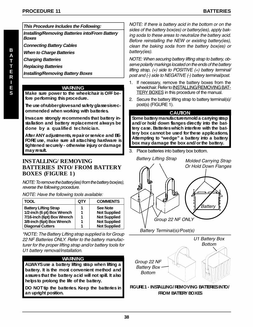
38
This Procedure Includes the Following:
Installing/Removing Batteries into/From BatteryBoxes
Connecting Battery Cables
When to Charge Batteries
Charging Batteries
Replacing Batteries
Installing/Removing Battery Boxes
WARNINGMake sure power to the wheelchair is OFF be-fore performing this procedure.
The use of rubber gloves and safety glasses is rec-ommended when working with batteries.Invacare strongly recommends that battery in-stallation and battery replacement always bedone by a qualified technician.After ANY adjustments, repair or service and BE-FORE use, make sure all attaching hardware istightened securely - otherwise injury or damagemay result.
INSTALLING/REMOVINGBATTERIES INTO/FROM BATTERYBOXES (FIGURE 1)NOTE: To remove the battery(ies) from the battery box(es),reverse the following procedure.
NOTE: Have the following tools available:
TOOL QTY COMMENTS
Battery Lifting Strap 1 See Note1/2-inch (6 pt) Box Wrench 1 Not Supplied7/16-inch (6pt) Box Wrench 1 Not Supplied3/8-inch (6pt) Box Wrench 1 Not SuppliedDiagonal Cutters 1 Not Supplied
*NOTE: The Battery Lifting strap supplied is for Group22 NF Batteries ONLY. Refer to the battery manufac-turer for the proper lifting strap and/or battery tools forU1 battery removal/installation.
WARNINGALWAYS use a battery lifting strap when lifting abattery. It is the most convenient method andassures that the battery acid will not spill. It alsohelps to prolong the life of the battery.DO NOT tip the batteries. Keep the batteries inan upright position.
NOTE: If there is battery acid in the bottom or on thesides of the battery box(es) or battery(ies), apply bak-ing soda to these areas to neutralize the battery acid.Before reinstalling the NEW or existing battery(ies),clean the baking soda from the battery box(es) orbattery(ies).
NOTE: When securing battery lifting strap to battery, ob-serve polarity markings located on the ends of the batterylifting strap, (+) side to POSITIVE (+) battery terminal/post and (-) side to NEGATIVE (-) battery terminal/post.
1. If necessary, remove the battery boxes from thewheelchair. Refer to INSTALLING/REMOVING BAT-TERY BOXES in this procedure of the manual.
2. Secure the battery lifting strap to battery terminal(s)/post(s) (FIGURE 1).
CAUTIONSome battery manufacturers mold a carrying strapand/or hold down flanges directly into the bat-tery case. Batteries which interfere with the bat-tery box cannot be used for these applications.Attempting to “wedge” a battery into a batterybox may damage the box and/or the battery.
3. Place batteries into battery box bottom.
FIGURE 1 - INSTALLING/REMOVING BATTERIES INTO/FROM BATTERY BOXES
Battery Lifting Strap
Group 22 NFBattery Box
Bottom
U1 Battery BoxBottom
Molded Carrying StrapOr Hold Down Flanges
Battery Terminal(s)/Post(s)
Group 22 NF ONLY
Battery
PROCEDURE 11 BATTERIES
BATTERIES

39
PROCEDURE 11BATTERIES
BATTERIES
CONNECTING BATTERY CABLES
WARNINGNEVER allow any of your tools and/or batterycable(s) to contact BOTH battery terminal(s)/post(s)at the same time. An electrical short may occurand serious personal injury or damage may occur.
The use of rubber gloves and safety glasses is rec-ommended when working with batteries.
Dual U1 or Dual Group 22 NF Battery Boxes
Perform one (1) of the following methods for connect-ing the battery cable(s):
A. FOR DUAL U1 BATTERIES - Use direct mountmethod. Refer to FIGURES 2 AND 3.
B. FOR DUAL GROUP 22 NF BATTERIES THATHAVE MOUNTING HOLES IN THE BATTERYTERMINAL(S)/POST(S) - Use direct mountmethod. Refer to FIGURES 2 AND 3.
C. FOR DUAL GROUP 22 NF BATTERIES THATDO NOT HAVE MOUNTING HOLES IN THEBATTERY TERMINAL(S)/POST(S) - Use batteryclamp method. Refer to FIGURES 4, 5 AND 6.
DIRECT MOUNT METHOD (FIGURE 2 AND 3).1. Install battery terminal cap(s) onto battery cable(s) as
follows (FIGURE 2):
DUAL U1 BATTERIES:A. ORANGE battery terminal cap onto RED battery
cable.
B. GRAY battery terminal cap onto BLACK batterycable.
DUAL GROUP 22 NF BATTERIES:A. RED battery terminal cap onto RED battery cable.
B. BLACK battery terminal cap onto BLACK bat-tery cable.
FIGURE 2 - CONNECTING BATTERY CABLES -DIRECT MOUNT METHOD
CAUTIONWhen connecting the battery cables to thebattery(ies), the battery cable(s) MUST be con-nected to the battery terminal(s)/post(s) asshown in DETAIL “A” or DETAIL “B” of FIGURE 3(depending on battery type), otherwise dam-age to the battery cable may result when in-stalling battery terminal caps.
2. Connect battery cable(s) to battery(ies) terminal(s)/post(s) as follows (DETAIL “A” or DETAIL “B” ofFIGURE 3, depending on battery type):
A. NEGATIVE (-) BLACK battery cable to NEGA-TIVE (-) battery terminal/post.
B. POSITIVE (+) RED battery cable to POSITIVE(+) battery terminal/post.
3. Secure the battery cable(s)/ring terminal(s) to thebattery terminal(s)/post(s), BLACK to NEGATIVE(-) and RED to POSITIVE (+), with the provided 1/4-20 x 7/8-inch hex flange screw and hex flangelocknut. Securely tighten. (DETAIL “A” or DETAIL“B” of FIGURE 3, depending on battery type).
4. Verify all battery cable(s)/ring terminal(s) are correctlyinstalled and securely tightened.
5. Slide terminal cap(s) down battery cable(s) and ontobattery clamps (FIGURE 3).
6. Secure each terminal cap in place with a tie-wrap(Use tie-wraps 11-1/2-inches long) (FIGURE 3).
NOTE: It will be necessary to trim excess tie-wrap in order toinstall the battery box top(s).
7. Install the battery box top(s).
8. Install the battery box(es) into the wheelchair. Referto INSTALLING/REMOVING BATTERY BOX(ES) inthis procedure of the manual.
NOTE: New Battery(ies) MUST be fully charged BEFOREusing, otherwise the life of the battery(ies) will be reduced.
9. If necessary, charge the battery(ies). Refer toCHARGING BATTERIES in this procedure of themanual.
Battery Cable
Battery TerminalCap
NOTE: Only one (1) battery cable and terminal cap shownfor clarity. Both caps install in the same manner.
INSTALLING BATTERY TERMINAL CAPS

40
PROCEDURE 11 BATTERIES
BATTERIES
1/4-20 x 7/8-Inch Hex Flange Screw
FIGURE 3 - CONNECTING BATTERY CABLES - DIRECT MOUNT METHOD
Orange BatteryTerminal Cap
POSITIVE(+) BatteryTerminal/
Post
U-1Battery
GrayBattery
TerminalCap
Tie-Wrap
NEGATIVE(-) BatteryTerminal/
Post
Tie-Wrap
1/4-20Hex
FlangeLocknut
Negative (-)Battery Terminal/
Post
1/4-20 x 7/8-Inch Hex Flange Screw
Positive (+) BatteryTerminal/Post
U1Battery
1/4-20 x 7/8-Inch Hex Flange Screw
NEGATIVE (-) BatteryTerminal/Post
Group 22NFBattery
POSITIVE (+) Battery Terminal/Post
POSITIVE (+) RedBattery Cable
NEGATIVE (-)Black Battery
Cable
DETAIL “B”
1/4-20Hex
FlangeLocknut
CONNECT BATTERYCABLE TO BATTERY
TERMINAL AS SHOWN.
DUAL U1 BATTERIES
BLACK BatteryTerminalCap
POSITIVE(+) BatteryTerminal/
Post
Group 22 NFBattery
REDBattery
TerminalCap
Tie-Wrap
NEGATIVE(-) BatteryTerminal/
Post
Tie-Wrap
DETAIL “A”DUAL GROUP 22 NF BATTERIES
CONNECTBATTERY
CABLE(S) RINGTERMINAL(S) TO
THIS SIDE OFBATTERY
TERMINAL(S)/POST(S)
DUAL U1 BATTERIES DUAL GROUP 22 NF BATTERIES

41
Battery CableBattery ClampCover
2. Install battery clamp covers onto battery cables asfollows (FIGURE 5):
A. RED battery clamp cover onto RED battery cable.
B. BLACK battery clamp cover onto BLACK bat-tery cable.
NOTE: Only one (1) battery cable and battery clamp coverare shown for clarity. Both battery clamp covers install inthe same manner.
BATTERY CLAMP METHOD (FIGURES 4, 5AND 6).
CAUTIONThe battery clamp of the POSITIVE (+) batteryterminal/post MUST be mounted in the posi-tion shown in FIGURE 4, otherwise the batterybox top cannot be installed properly.
1. Perform one (1) of the following:
A. If the battery clamp of the POSITIVE (+) batteryterminal/post is NOT mounted in the orientationshown in FIGURE 4, perform the following:
● Loosen the hex nut that secures the batteryclamp to the POSITIVE (+) battery terminal/post.
CAUTIONWhen tightening the clamps, alwaysuse a box wrench. Pliers will “round off”the nuts. NEVER wiggle the batteryterminal(s)/post(s) when tightening. Thebattery may become damaged.
● Remove the battery clamp from the POSI-TIVE (+) battery terminal/post.
● Reposition the battery clamp on the POSI-TIVE (+) battery terminal/post as shown inFIGURE 4.
● Securely tighten the hex nut that secures thebattery clamp to the positive (+) battery ter-minal/post.
B. If the battery clamp on the POSITIVE (+) batteryterminal/post is positioned as shown in FIGURE4, proceed to STEP 2.
NEGATIVE (-) BatteryTerminal/Post and Battery Clamp
POSITIVE (+) Battery Terminal/Post(Note position of battery clamp)
FIGURE 4 - BATTERY CLAMP METHOD
Group 22NFBattery
HexNut
FIGURE 5 - CONNECTING BATTERY CABLES -BATTERY CLAMP METHOD
CAUTIONWhen connecting the battery cable/ring terminal(s)to the battery(ies) clamp(s), the battery cable(s)MUST be connected in the position shown in DETAIL“A”, otherwise damage may occur to the batterycable and/or battery clamp covers.
3. Connect battery cable(s) to battery(ies) terminal(s)/post(s) as follows (DETAIL “A”):
A. NEGATIVE (-) BLACK battery cable/ring termi-nal between the mounting plate and battery clampof NEGATIVE (-) battery terminal/post.
B. POSITIVE (+) RED battery cable/ring terminal be-tween the mounting plate and battery clamp bat-tery clamp of POSITIVE (+) battery terminal/post.
4. Secure the battery cable(s)/ring terminal(s) to the batteryclamp(s), BLACK to NEGATIVE (-) and RED to POSI-TIVE (+), with existing hex screws. Securely Tighten(DETAIL “A”).
5. Verify battery cable ring terminal(s) are correctly installedand securely tightened.
6. Slide battery clamp covers down battery cables and ontobattery terminals (DETAIL “B”).
7. Secure each terminal cap in place with a tie-wrap (Usetie-wraps 11-1/2-inches long) (DETAIL “B”).
NOTE: It will be necessary to trim excess tie-wrap in order toinstall the battery box top(s).
8. Install the battery box top(s).
CORRECT ORIENTATION OF THE POSITIVE (+)BATTERY TERMINAL/POST BATTERY CLAMP
INSTALLING BATTERY CLAMP COVERS
PROCEDURE 11BATTERIES
BATTERIES

42
9. Install the battery box(es) into the wheelchair. Referto INSTALLING/REMOVING BATTERY BOX(ES) inthis procedure of the manual.
NOTE: New Battery(ies) MUST be fully charged BEFOREusing, otherwise the life of the battery(ies) will be reduced.
10. If necessary, charge the battery(ies). Refer toCHARGING BATTERIES in this procedure of themanual.
PROCEDURE 11 BATTERIES
BATTERIES
DETAIL “A”
DETAIL “B”
NOTE: Battery clamps exploded away for clarification purposes only.
Mounting Plate
FIGURE 6 - CONNECTING BATTERY CABLES - BATTERY CLAMP METHOD
CONNECTING BATTERY CABLE(S) TO BATTERY(IES) TERMINAL(S)/POST(S)
Hex Screw
Negative (-) BLACKBattery Cable
Positive (+) REDBattery Cable
Battery Clamp
POSITIVE (+) Battery Terminal/Post and Battery Clamp
NEGATIVE (-) Battery Terminal/Post and Battery Clamp
Positive (+) REDBattery Cable
Negative (-) BLACKBattery Cable
Group 22NF Battery
POSITIVE (+) BatteryTerminal/Post
Mounting Plate
Group 22NF BatteryNEGATIVE (-) Battery Terminal/Post
TOP VIEW
EXPLODEDVIEW
RED Battery Clamp Cover
NEGATIVE (-) BatteryTerminal/Post
Tie-Wrap
BLACK Battery Clamp CoverGroup 22NF Battery
Tie-Wrap
POSITIVE (+) BatteryTerminal/Post

43
CHARGING BATTERIES (FIGURE 8)
WARNINGNever attempt to recharge the batteries by at-taching cables directly to the battery terminalsor clamps. Always use the recharging plug lo-cated on the controller OR the side/rear of thewheelchair frame.DO NOT attempt to recharge the batteries andoperate the power wheelchair at the same time.During use and charging, unsealed batteries willvent hydrogen gas which is explosive in the rightconcentration with air.
CAUTIONAlways charge new batteries fully BEFORE initialuse or battery life will be reduced.
NOTE: As a general rule, batteries should be rechargeddaily to assure the longest possible life and minimize therequired charging time. Plan to recharge the batterieswhen it is anticipated the wheelchair will not be used forseveral days.
The range per battery charge using recommended bat-teries should be approximately 5 to 9 hours of typical op-eration. Extensive use on inclines or age of batteries maysubstantially reduce per charge mileage.
Description and Use of Battery Chargers
The charger automatically reduces the amount of chargefrom an initially high rate to a zero reading at a fully chargedcondition.
SHUTOFF PROCEDURE.A. For PRONTOR2 Models - If left unattended, the
charger will automatically shut-off when full chargeis obtained.
B. For PRONTOR2-250 Series Models - The Charger out-put and green light will stay ON until the power switchon the battery charger is moved to the OFF position.
There are some basic concepts which will help youunderstand this automatic process:
The amount of electrical current drawn within a given timeto charge a battery is called “charge rate”. If, due to us-age, the charge stored in the battery is low, the chargerate is high. (For PRONTOR2 Models - this is indicatedby the green light on the charger. Initially, the green lightwill stay illuminated for a short period of time followed bya longer period of off time.)
As a charge builds up, the charge rate is reduced, andthe following will occur:
A. For PRONTOR2-250 Series Models - the green lightwill stay illuminated for a longer period of timefollowed by a shorter off time.
PROCEDURE 11BATTERIES
BATTERIES
Battery GaugeDisplay (BGD)
MKIV- RII JOYSTICK
Battery DischargeIndicator (BDI)
MKIV X, A OR A+ JOYSTICK
FIGURE 7 - WHEN TO CHARGE BATTERIES
NOTE: MKIV X Shown.
WHEN TO CHARGE BATTERIES(FIGURE 7)It is advantageous to recharge daily rather than only whennecessary. In fact, a battery’s life is extended if the chargelevel is maintained well above a low condition.
MKIV RII Joystick
BATTERY DISCHARGE INDICATOR (BDI) is located atthe front of the joystick housing and provides informationon the remaining charge in the batteries. At FULL chargethe BDI will be GREEN. As the battery becomes discharged,the BDI indicator will turn AMBER (YELLOW), then REDand finally FLASHING RED. If the BDI is FLASHING RED,the user should charge the batteries as soon as possible.
NOTE: Accurate readings are displayed when in neutral.
MCC-MKIV X, A or A+ Joystick
BATTERY GAUGE DISPLAY (BGD) is the bar graph dis-play located on the MKIV X, A or A+ joystick. It will keep youinformed as to power availability. A visual warning is givenbefore the power becomes too low to operate the wheelchair.At full charge the two (2) LEFT segments and the farthestRIGHT segment of the bar graph will be illuminated. As thebattery becomes discharged, the farthest RIGHT segmentwill progressively move to the LEFT until only the last two (2)bars (LEFT) are illuminated. At this level the last two (2) bars(LEFT) will start to Flash ON and OFF to indicate that the enduser should charge the batteries as soon as possible.
NOTE: Accurate readings are displayed when in neutral.

44
PROCEDURE 11 BATTERIES
BATTERIES
FIGURE 8 - CHARGING BATTERIES
FromBatteryCharger
Battery Charger Connector
From Battery Charger
Three (3)Pronged Plug
Battery Charger
Charger Cable
Battery Boxes
Top Viewof Wheelchair
Base Frame
Battery Charger Mount Bracket
Required Items:
TOOL QUANTITY COMMENTS
Battery Charger 1 Supplied✪✪✪✪✪ Extension Cord 1 Not Supplied
✪ 3-prong plug, 15 ampere current rating; industrial type
B. For PRONTOR2 Models - the battery chargerrate decreases to a "trickle charge".
NOTE: If performing the charging procedures indepen-dently, READ and CAREFULLY follow the individual in-structions for each charger (supplied or purchased).
NOTE: If charging instructions are not supplied, consult aqualified service technician for proper procedures.
Wheelchairs Equipped With MCC-Mark IVJoystick (Detail "A" of FIGURE 8)
1. Attach the battery charger connector to the chargercable/battery harness.
2. Plug the charger’s AC power cord, or extension, intothe grounded 120 VAC wall outlet.
3. Wait until charging is complete.
NOTE: Allow eight (8) hours for normal charging. Largerbatteries (greater than 55 ampere-hours) or severely dis-charged batteries may require up to sixteen (16) hours tobe properly charged and equalized.
NOTE: PRONTOR2 ONLY - If the charger operates forsixteen (16) hours and is unable to fully charge the batter-ies, an internal timer turns the charger off and begins tofast blink the green light.
NOTE: If the batteries need to be charged more often ortake longer to charge than normal, they may need to bereplaced. Contact an authorized dealer for service.
Wheelchairs Equipped With Mark IV RIIJoystick (Detail "B" of FIGURE 8)
1. Attach the battery charger connector to the chargerport on the FRONT of the joystick.
2. Plug the charger’s AC power cord, or extension, intothe grounded 120 VAC wall outlet.
3. Wait until charging is complete.
NOTE: Allow eight (8) hours for normal charging. Largerbatteries (greater than 55 ampere-hours) or severely dis-charged batteries may require up to sixteen (16) hours tobe properly charged and equalized.
NOTE: PRONTOR2 ONLY - If the charger operates forsixteen (16) hours and is unable to fully charge the batter-ies, an internal timer turns the charger off and begins tofast blink the green light.
NOTE: If the batteries need to be charged more often ortake longer to charge than normal, they may need to bereplaced. Contact an authorized dealer for service.
DETAIL "A"
DETAIL "B"
Front View ofJoystick
Charger Port
Battery Charger Three (3)Pronged Plug
From BatteryCharger
Top View of Wheelchair
ChargerPort
Joystick
BatteryBoxes

45
PROCEDURE 11BATTERIES
BATTERIES
REPLACING BATTERIES
WARNINGMost batteries are not sold with instructions. How-ever, warnings are frequently noted on the cellcaps. Read them carefully, otherwise injury ordamage can occur.
NOTE: Invacare recommends that both batteries be re-placed if one (1) battery is defective.
Recommended Battery Types
WARNINGThe warranty and performance specifications con-tained in this manual are based on the use of deepcycle gel cell or sealed lead acid batteries.Invacare strongly recommends their use as thepower source for this unit.
CAUTIONFailure to use the correct battery size and/or volt-age may cause damage to your wheelchair andgive you unsatisfactory performance.
NOTE: The recommended battery type is 22NF deepcycle.
1. Remove the battery boxes from the wheelchair. Referto REMOVING/INSTALLING BATTERY BOXES inthis procedure of the manual.
2. Remove existing batteries from the battery boxes. Referto INSTALLING/REMOVING BATTERIES INTO/FROM BATTERY BOXES in this procedure of themanual.
3. Clean the new battery terminals.
4. Install the new batteries into the battery boxes. Referto INSTALLING/REMOVING BATTERIES INTO/FROM BATTERY BOXES in this procedure of themanual.
Cleaning Battery Terminals
WARNINGDO NOT allow the liquid in the battery to come incontact with skin, clothes or other possessions. It isa form of acid and harmful or damaging burnsmay result. Should the liquid touch your skin, washthe area immediately and thoroughly with coolwater. In serious cases or if eye contact is made,seek medical attention IMMEDIATELY.NEVER smoke or strike a match near batteries. Ifthe caps of the battery cells are removed, NEVERlook directly into them while charging batteries.
1. Examine battery clamps and terminals for corrosion.
2. If applicable, verify that the plastic caps are in placeover the battery cell holes.
3. Cut the tie wraps around the terminal caps/covers.
4. Slide the terminal cap/cover up the wire to exposethe battery terminal.
5. Clean the terminals and inside the battery clamps byusing a battery cleaning tool, wire brush, or mediumgrade sand paper.
NOTE: When done, these areas should be shiny, not dull.
6. Carefully dust off all metal particles.
7. Slide the terminal cap/cover back down the wireto cover the battery terminal.
8. Secure the terminal cap/cover using NEW tiewraps.
INSTALLING/REMOVING BATTERYBOXES (FIGURE 9)NOTE: To remove the battery boxes from the wheelchair,reverse the following procedure.
WARNINGIf the wheelchair is equipped with the removablefootboard AND it is installed in the heighest posi-tion, it is necessary to remove the footboard plateBEFORE removing the battery boxes. Otherwise,injury can occur.
To remove the removable footboard, refer to REMOV-ING THE REMOVABLE FOOTBOARD ASSEMBLYFROM THE WHEELCHAIR in PROCEDURE 3 of thismanual.
NOTE: Motors should be in the engaged position whenremoving/installing batteries. Refer to ENGAGING/DISEN-GAGING MOTORS in PROCEDURE 8 of this manual.
1. Verify that the ON/OFF switch on the joystick is in theOFF position.
2. If necessary, remove the front and rear shrouds. Referto REMOVING/INSTALLING SHROUDS in PROCE-DURE 9 of this manual.
WARNINGUse extreme care when installing/removing thebattery boxes.
NEVER unplug the battery cables by pulling onthe wires. Unplug the battery cables by pull-ing on the connector ONLY. Otherwise injuryor damage may result.
When removing the battery boxes from thewheelchair, remove the rear battery box first.
NOTE: RIGHT and LEFT are determined by sitting inthe wheelchair..

46
BATTERIES
PROCEDURE 11 BATTERIES
3. Position the battery boxes onto the battery tray inthe following order:A. TWO (2) connector battery box in FRONT so
that the "open" ends of the connectors are fac-ing the REAR of the chair.
B. ONE (1) connector battery box in REAR sothat the flying lead is on the RIGHT side of thewheelchair.
NOTE: Make sure the leads that connect the REARbattery box to the FRONT battery box are on the sameside.
4. Position retaining straps around each battery boxas shown in DETAIL "B" of FIGURE 7 and clipretaining strap together.
5. Connect the REAR battery box lead to the FRONTbattery box lead.
6. Connect the FRONT battery box lead to the wir-ing harness.
7. If necessary, reinstall the removeable footboard.Refer to REMOVING THE REMOVABLEFOOTBOARD ASSEMBLY FROM THE WHEEL-CHAIR in PROCEDURE 3 of this manual.
FIGURE 9 - INSTALLING/REMOVING BATTERY BOXES
Retaining Strap
Rear Battery Box(One (1) Connector)
Front Battery Box(Two (2) Connector)
RetainingStrap Clip
Rear BatteryBox Lead
(Flying Lead)
Front BatteryBox Lead
FrontBattery Box
Lead (ToWiring
Harness)
Open Ends ofConnector Face
Rear of Chair
REAR OF CHAIR
FRONT OF CHAIR

47
LIMITED WARRANTYPLEASE NOTE: THE WARRANTY BELOW HAS BEEN DRAFTED TO COMPLY WITH FEDERAL LAW APPLICABLE TOPRODUCTS MANUFACTURED AFTER JULY 4, 1975.
This warranty is extended only to the original purchaser/user of our products.
This warranty gives you specific legal rights and you may also have other legal rights which vary from stateto state.
With regards to the original purchaser/user only, Invacare warrants the side frames to be free from de-fects in materials and workmanship for a period of five (5) years from date of purchase; electronics for aperiod of one (1) year from the date of purchase; motors and gearboxes for a period of eighteen (18)months for Pronto models with motors that have motor locks and a period of twelve (12) months forPronto models with motors that have clutches from the date of purchase; all remaining components(including gas cylinders for recliners) for one (1) year from the date of purchase except upholsteredmaterials, padded materials and tires/wheels. If within such warranty period any product shall be provento be defective, such product shall be repaired or replaced, at Invacare's option. This warranty does notinclude any labor or shipping charges incurred in replacement part installation or repair of any suchproduct. Invacare's sole obligation and your exclusive remedy under this warranty shall be limited to suchrepair and/or replacement.
For warranty service, please contact the dealer from whom you purchased your Invacare product. Inthe event you do not receive satisfactory warranty service, please write directly to Invacare at the ad-dress on the bottom of the back cover. Provide dealer's name address, date of purchase, indicatenature of the defect and, if the product is serialized, indicate the serial number. Do not return products toour factory without our prior consent.
LIMITATIONS AND EXCLUSIONS: THE FOREGOING WARRANTY SHALL NOT APPLY TO SERIAL NUMBEREDPRODUCTS IF THE SERIAL NUMBER HAS BEEN REMOVED OR DEFACED, PRODUCTS SUBJECT TO NEGLI-GENCE, ACCIDENT, IMPROPER OPERATION, MAINTENANCE OR STORAGE, COMMERCIAL OR INSTITUTIONALUSE, PRODUCTS MODIFIED WITHOUT INVACARE'S EXPRESS WRITTEN CONSENT INCLUDING, BUT NOT LIM-ITED TO, MODIFICATION THROUGH THE USE OF UNAUTHORIZED PARTS OR ATTACHMENTS; PRODUCTS DAM-AGED BY REASON OF REPAIRS MADE TO ANY COMPONENT WITHOUT THE SPECIFIC CONSENT OF INVAC-ARE, OR TO A PRODUCT DAMAGED BY CIRCUMSTANCES BEYOND INVACARE'S CONTROL, AND SUCHEVALUATION WILL BE SOLELY DETERMINED BY INVACARE. THE WARRANTY SHALL NOT APPLY TO PROBLEMSARISING FROM NORMAL WEAR OR FAILURE TO ADHERE TO THESE INSTRUCTIONS. A CHANGE IN OPERAT-ING NOISE, PARTICULARLY RELATIVE TO MOTORS AND GEARBOXES DOES NOT CONSTITUTE A FAILURE. ALLSUCH DEVICES WILL EXHIBIT A CHANGE IN OPERATING NOISE DUE TO AGING.
THE FOREGOING WARRANTY IS EXCLUSIVE AND IN LIEU OF ALL OTHER EXPRESS WARRANTIES. IMPLIEDWARRANTIES, IF ANY, INCLUDING THE IMPLIED WARRANTIES OF MERCHANTABILITY AND FITNESS FOR APARTICULAR PURPOSE, SHALL NOT EXTEND BEYOND THE DURATION OF THE EXPRESSED WARRANTY PRO-VIDED HEREIN AND THE REMEDY FOR VIOLATIONS OF ANY IMPLIED WARRANTY SHALL BE LIMITED TO REPAIROR REPLACEMENT OF THE DEFECTIVE PRODUCT PURSUANT TO THE TERMS CONTAINED HEREIN. INVACARESHALL NOT BE LIABLE FOR ANY CONSEQUENTIAL OR INCIDENTAL DAMAGES WHATSOEVER.
THIS WARRANTY SHALL BE EXTENDED TO COMPLY WITH STATE/PROVINCIAL LAWS AND REQUIREMENTS.
WARRANTY
WARRANTY

���������������� �������������� !
�� ��� ����������"�#$�%��& '����#�����(��"�!��)%� *����������������������& +,-.��/�"� �(/���& � �0 ��(� ���1&������/� ����� ��%%�%%�'2�����(��� 3
�
4...���������� �0 ��(� �55.678494+ �+��6�,������"�:..866687,.. ,.+8:,.8::6: � �!� ��,,846:����������;��(� ��9.,+7.4���������������<6=�8�.,>..
WARRANTY