Embed Size (px)
Citation preview
BREAST CANCER PALPATION SIMULATORUSING PNEUMATIC ACTUATOR
Masahiro TAKAIWA* , Takeshi MATSUNO*, Daisuke SASAKI* andToshiro NORITSUGU**
* The Graduate School of Natural Science and TechnologyOkayama University
3-1-1 Tsusimanaka Kitaku Okayama, 700-8530 Japan(E-mail:[email protected])
** Tsuyama National College of Technology624-1 Numa Tsuyama city Okayama, 708-8509 Japan
ABSTRACT
Among the Japanese women, the disease rate of breast cancer became the most highest one, over ahead of thatof stomach cancer around 1997. However, if the cancer is still remained at a small part of breast, the existencerate is reported to be 92 % that is pretty higher than that of another cancer. It also shows the importanceof early detection. Detection of breast cancer is implemented by both palpation diagnosis and Mammography(X-ray photograph of breast). We focused on a palpation diagnosis which requires for a medical doctor to havea highly skilled technique. From a view of medical education, there is strong need for palpation simulator andsome equipment using robot technology or VR one are being developed.Actually, some palpation simulators has already come onto the market, but they don’t have function to adjustsize or position or magnitude of stiffness of lump. In this study, we aim at developing a palpation simulatorwhich has pneumatic cylinder placed in diagonal and realizing high functional palpation diagnosis.
KEY WORDS
Breast cancer, Palpation simulator, Pneumatic actuator, Force display
INTRODUCTION
Disease rate of breast cancer in Japanese womenhas been gradually increasing and currently it reachedat the highest one overcoming that of stomach cancerin 1997[1].
However, 5 year survival rate of breast cancer isquite high of 95 % comparing with another types ofcancer, which indicates the importance of early de-tection simultaneously.
Detection of breast cancer is done by both of
a palpation diagnosis by a medical doctor and aMammography(X-ray photograph) of a breast. Pal-pation diagnosis requires medical doctors to havehighly skilled technique.
In the mean while, an importance of self diagnosisdone by general women is also pointed out. However,most of them don’t know the tactile feeling of a lumpespecially it is still small in the early period of breastcancer.
From these point of view, a palpation simulator isrequired as training simulator for medical doctors or
Copyright © 2014 JFPS. ISBN 4-931070-10-8
Proceedings of the 9th JFPS International Symposiumon Fluid Power, Matsue, 2014
Oct. 28 - 31, 2014
528
2D2-1 Keynote 3

its candidates and as a specimen for general womenfor their self diagnosis and some types of palpationsimulator have been developed[2] [3] [4].Currently most used palpation simulators will be
the passive type commercial products eg.[5]. Theyare made of silicone rubber and has a lump modelinside. Apparently, they are well fabricated to imitatean actual women breast, but the inside lump modelis passive one so its shape, place and a mechanicalproperty can not be regulated, which may declare theeffect as a palpation simulator.In this study, we developed a palpation simulator
that displays reaction force from a lump, that is calcu-lated from a mechanical property of the virtual lumpand relative position between a finger and the lumpin a VR environment. Force displaying mechanismis a moving platform contacting with an operator’sfinger, which is driven with perpendicularly placedpneumatic cylinders. A stiffness control system basedon a force control is employed at the pneumatic servosystem that drives the orthogonal axis independently.The effectiveness of the proposed control system
are verified through some experiments.
PALPATION SIMULATOR
Schematic DiagramFig.1 shows a developed palpation simulator. A
moving platform slides on linear guides placed inorthogonal(so called x-y stage) and each D.O.F.is driven with friction less type pneumatic cylin-der(Airpel co. 9.3mm in diameter, 50mm in stroke)as shown in Fig.1(a). An acceleration sensor (ZMPCo. Tiny-cube) is mounted on a moving platform.An operator implements palpation motion by feel-ing a reaction force through a physical breast modelmounted on a moving platform as shown in Fig.1(b).In generally, palpation diagnosis is done by spatialmotion, the third driving axis for z direction is cur-rently under the construction. In this paper, we aimto investigate the fundamental control performanceof the developed servo system and its feasibility as apalpation simulator.Pneumatic Driving SystemFig.2 shows pneumatic driving circuit for one pneu-
matic cylinder. Pressure in each cylinder’s chamber,p1, p2 are detected by pressure sensors and the dis-placement of piston rod ℓ is measured by wire typelinear encoder.A control signal drives a flow control valve
(FESTO Co. MPYE-5-M5-0103B) through D/A con-verter(resolution of 12 bit), which regulates the pres-sure in a head side chamber. Supply pressure ps isset to be 400 [kPa]. The piston rod side chamber ispressurized at constant pressure of 200 [kPa], a half
encoder
cylinder
cylinder
encoderlinear guide
y
x
moving platform
(a) linear driving mechanism
(b) aspect of palpation motion
Figure 1: Palpation simulator
D/Aconverter
A/Dconverter
Encodercounter Computer
Valve
Pressuresensor
Pressuresensor
Encorder
Pneumaticcylinder
mp2 A2
p1 A1
u
ℓ
ps
pa
fℓ
link i
ps
2
Accelerationsensor
Figure 2: Pneumatic driving circuit
of supply pressure ps. Control system is implementedon a RTAI, a real-time extension of Linux with sam-pling period of 5 [ms].
Dynamic equation of generation force of a cylin-der fg = [fgx, fgy]
T = [p1xA1x − p2xA2x, p1yA1y −p2yA2y]
T is described as
Tpdfgdt
= −fg +Kpu−Kvdℓ
dt(1)
Copyright © 2014 JFPS. ISBN 4-931070-10-8 529
Fg(s)Fr(s) 1
ms2 + bs
Fℓ(s)
+
+Force control
system
ms2 + bs
+
+
restriction force compensation
Fd(s) L(s)
(a) force control system
U (s)
Q(s)
1
1 + Tqs
Fg(s)
Filter Nominal Model
+
+
+
-
-
-
Kp/Kv
sL(s)
1 + Tpns
Kpn
1
Kpn
Fd(s) Kp
1 + Tps
P (s)Plant Model
P−1
n (s)
(b) disturbance observer based force control system
Figure 3: Generation force control system
,where u = [ux, uy]T ,Tp = diag{Tpx, Tpy},Kp =
diag{Kpx,Kpy}, and Kv = diag{Kvx,Kvy} are con-trol input vector(corresponds to input voltage of con-trol valve), time constant of generation force re-sponse, static gain matrix and influence gain matrixof piston velocity,respectively.Motion of equation is derived as
fg + fℓ = md2ℓ
dt2+ b
dℓ
dt(2)
,where fℓ = [fℓx, fℓy]T , m = diag{mx,my}, b =
diag{bx, by} is external force vector, mass matrix andviscous coefficient matrix. In generally, fℓ contains aforce applied by an operator and friction force, but,in this study, a coulomb friction force is neglected dueto a low friction type cylinder.Eq.(1) shows that generation force has first order
lag for control input and influence of piston velocityworks as a disturbance. In order to display referenceforce accurately to an operator ’s finger, active forcecontrol is required and the control system should havehigh band width to track to the reference and highrobustness against disturbance.
CONTROL SYSTEM
From Eq.(2), if the generation force fg tracked com-pletely to the reference force with inertial and damp-
ing force compensation fr + md2ℓ
dt2+ b
dℓ
dt, then the
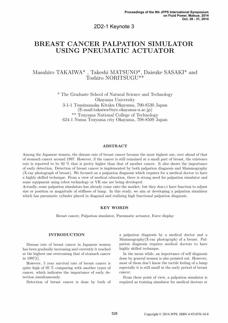
force that an operator feels can be controlled with fr.Fig.3(a) shows a force control system, where a
block with red line is a generation force control sys-tem as shown in Fig.3(b). In a feedback compensa-tion loop of inertia and viscous force (ms2+ bs)H(s),
Figure 4: Virtual lump in VR environment
an acceleration and velocity signal are obtained froman acceleration sensor attached on a moving platformand derivation of displacement, respectively.
A disturbance observer[6] is introduced to formgeneration force control system shown in Fig.3 (b),where P (s), Pn(s) and Q(s) is a plant transfer func-tion derived from Eq.(1), plant nominal model andlow pass filter to ensure closed loop stability, respec-tively. The input output relation of the closed loopsystem is described as follows.
Fg(s) =1
P−1(s)(1−Q(s)) + Pn(s)−1Q(s)Fd(s)
=1−Q(s)
P−1(s)(1−Q(s)) + Pn(s)−1Q(s)D(s)
(3)
, where Fd(s) is desired force vector and disturbance
D(s) =Kp
KvsL(s).
In a disturbance observer, control performance de-pends on design of Q(s). The smaller the time con-stant of Q(s) is set, the closer the closed loop trans-fer function close to the plant’s nominal model Pn(s)and the lower the influence of disturbance appears onFg(s). However small time constant of Q(s) tends todeclare the stability of the closed loop system. In thisstudy, we set the time constant of Q(s) as small aswe can within a stable range.
LUMP RECOGNITION IN VRENVIRONMENT
Fig.4 shows a virtual lump made in VR environ-ment using OpneGL. A spherical shell is introducedas a lump model for simplicity. Beside of the lumpmodel, the position of finger is indicated with a smallobject, which moves together with actual position ofa moving platform. Through this VR environment,an operator feels a reaction force from our palpation
Copyright © 2014 JFPS. ISBN 4-931070-10-8 530
Kn Kt
t
n
Σo
y
x
Σb
lump model
base coordinate system
object coordinate system
finger point
Figure 5: Geometrical model of lump
Fg(s)Fr(s) 1
ms2 + bs
Fℓ(s)
+
+Force control
system
ms2 + bs
+
+
restriction force compensation
Fd(s)R
TKR
target stiffness matrixL(s)
Lr(s)
+-
Figure 6: Stiffness control system
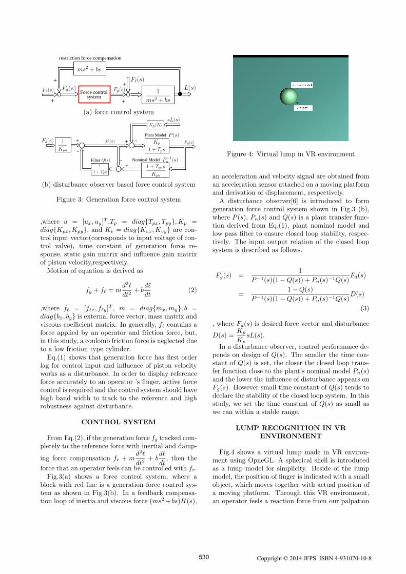
simulator and watches an interaction between a lumpmodel and finger as shown in Fig.4.Fig.5 shows a geometrical model of a virtual lump.
An object coordinate frame Σo is set on the surfaceof a lump, where its origin is match with the nearestpoint on the surface from a finger point and orthog-onal axis corresponds to the normal and tangentialdirection, respectively. A stiffness for normal direc-tion is set large and that for tangential is set small. Adisplacement vector p = [n, t]T on Σo is related witha displacement vector ℓ on Σb as
p = Rℓ =
[cos θ − sin θsin θ cos θ
]ℓ (4)
, where R is coordinate transfer matrix.From Eq.(4) and a principle of virtual work, rela-
tion between reference force vector and displacementone on Σb is obtained as
fr = RTKR∆ℓ = RT
[Kn 00 Kt
]R∆ℓ (5)
,where K is stiffness matrix expressed in Σo.Fig.6 shows a force control based stiffness control
system. When finger contact with a virtual lump,reference position Lr(s) corresponds to the origin ofΣo as shown in Fig.5
EXPERIMENTAL RESULTS
Fundamental force control performancesFig.7 shows a step response of generation force with
different reference force of 1.0 and 5.0 [N]. The moving
5 5.5
0
2
reference
t [s]
forc
e [N
] x axis
y axis
(a) reference force of 1.0 [N/mm]
5 5.5
0
2
4
6
reference
t [s]fo
rce [N
]
x axis
y axis
(b) reference force of 5.0 [N/mm]
Figure 7: Step response in generation force
platform is fixed by a finger to keep a volume of acylinder chamber at constant. For all of the referenceforce, the rising time of transient response is about0.05 [s].
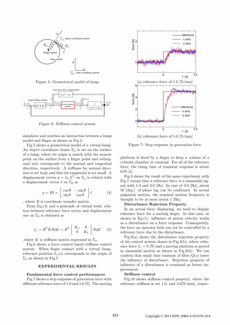
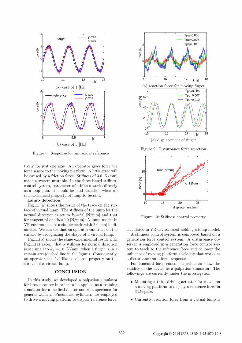
Fig.8 shows the result of the same experiment withFig.7 except that a reference force is a sinusoidal sig-nal with 1.0 and 3.0 [Hz]. In case of 3.0 [Hz], about50 [deg.] of phase lag can be confirmed. In actualpalpation motion, the required motion frequency isthought to be at most about 1 [Hz],
Disturbance Rejection Property
In an actual force displaying, we need to displayreference force for a moving finger. In this case, asshown in Eq.(1), influence of piston velocity worksas a disturbance on a force response. Consequently,the force an operator feels can not be controlled by areference force due to the disturbance.
Fig.9(a) shows the disturbance rejection propertyof the control system shown in Fig.3(b), where refer-ence force fr = 0 [N] and a moving platform is movedin sinusoidal motion as shown in Fig.9(b). We canconfirm that small time constant of filter Q(s) lowerthe influence of disturbance. Rejection property ofinfluence of a disturbance is remained as future im-provement.
Stiffness control
Fig.10 shows stiffness control property, where thereference stiffness is set 1.0, and 2.0[N/mm], respec-
Copyright © 2014 JFPS. ISBN 4-931070-10-8 531
10 11 12 13
-2
0
2
4y-axisx-axis
target
t [s]
forc
e [N
]
(a) case of 1 [Hz]
6 6.5 7
-2
0
2
4
t [s]
forc
e [
N]
reference x axisy axis
(b) case of 3 [Hz]
Figure 8: Response for sinusoidal reference
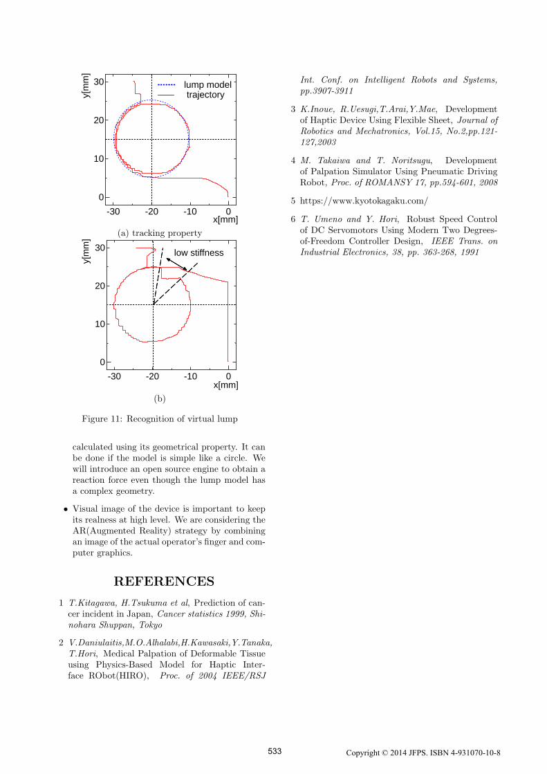
tively for just one axis. An operator gives force viaforce sensor to the moving platform. A little error willbe caused by a friction force. Stiffness of 3.0 [N/mm]made a system unstable. In the force based stiffnesscontrol system, parameter of stiffness works directlyas a loop gain. It should be paid attention when weset mechanical property of lump to be stiff.Lump detectionFig.11 (a) shows the result of the trace on the sur-
face of virtual lump. The stiffness of the lump for thenormal direction is set to kn=2.0 [N/mm] and thatfor tangential one kt=0.0 [N/mm]. A lump model inVR environment is a simple circle with 2.0 [cm] in di-ameter. We can see that an operator can trace on thesurface by recognizing the shape of a virtual lump.Fig.11(b) shows the same experimental result with
Fig.11(a) except that a stiffness for normal directionis set small to kn =1.0 [N/mm] when a finger is in acertain area(dashed line in the figure). Consequently,an operator can feel like a collapse property on thesurface of a virtual lump.
CONCLUSION
In this study, we developed a palpation simulatorfor breast cancer in order to be applied as a trainingsimulator for a medical doctor and as a specimen forgeneral women. Pneumatic cylinders are employedto drive a moving platform to display reference force,
15 16 17 18-2
0
2
Tpq=0.005
Tpq=0.007
Tpq=0.010
t [s]
forc
e [
N]
(a) reaction force for moving finger
15 16 17 18
0
20
40
60
Tpq=0.005
Tpq=0.007
Tpq=0.010
t [s]
forc
e [N
](a) displacement of finger
Figure 9: Disturbance force rejection
10 15 20 25
0
10
K=1 [N/mm]
K=2 [N/mm]
displacement [mm]
forc
e [
N]
Figure 10: Stiffness control property
calculated in VR environment holding a lump model.A stiffness control system is composed based on a
generation force control system. A disturbance ob-server is employed in a generation force control sys-tem to track to the reference force and to lower theinfluence of moving platform’s velocity that works asa disturbance on a force response.
Fundamental force control experiments show thevalidity of the device as a palpation simulator. Thefollowings are currently under the investigation.
• Mounting a third driving actuator for z axis ona moving platform to display a reference force in3-D space.
• Currently, reaction force from a virtual lump is
Copyright © 2014 JFPS. ISBN 4-931070-10-8 532
-30 -20 -10 0
0
10
20
30
x[mm]
y[m
m]
lump modeltrajectory
(a) tracking property
-30 -20 -10 0
0
10
20
30
x[mm]
y[m
m]
low stiffness
(b)
Figure 11: Recognition of virtual lump
calculated using its geometrical property. It canbe done if the model is simple like a circle. Wewill introduce an open source engine to obtain areaction force even though the lump model hasa complex geometry.
• Visual image of the device is important to keepits realness at high level. We are considering theAR(Augmented Reality) strategy by combiningan image of the actual operator’s finger and com-puter graphics.
REFERENCES
1 T.Kitagawa, H.Tsukuma et al, Prediction of can-cer incident in Japan, Cancer statistics 1999, Shi-nohara Shuppan, Tokyo
2 V.Daniulaitis,M.O.Alhalabi,H.Kawasaki,Y.Tanaka,T.Hori, Medical Palpation of Deformable Tissueusing Physics-Based Model for Haptic Inter-face RObot(HIRO), Proc. of 2004 IEEE/RSJ
Int. Conf. on Intelligent Robots and Systems,pp.3907-3911
3 K.Inoue, R.Uesugi,T.Arai,Y.Mae, Developmentof Haptic Device Using Flexible Sheet, Journal ofRobotics and Mechatronics, Vol.15, No.2,pp.121-127,2003
4 M. Takaiwa and T. Noritsugu, Developmentof Palpation Simulator Using Pneumatic DrivingRobot, Proc. of ROMANSY 17, pp.594-601, 2008
5 https://www.kyotokagaku.com/
6 T. Umeno and Y. Hori, Robust Speed Controlof DC Servomotors Using Modern Two Degrees-of-Freedom Controller Design, IEEE Trans. onIndustrial Electronics, 38, pp. 363-268, 1991
Copyright © 2014 JFPS. ISBN 4-931070-10-8 533