Embed Size (px)
DESCRIPTION
bycarpel sistemi per carriponte
Citation preview

2

3
LINEA PORTACAVI “TIPO EUROPEO” CABLE CARRYING LINE “EUROPEAN” TYPE
La linea portacavi tipo EUROPEO è un sistema pratico, efficiente e si-
curo per la distribuzione dell’energia, sia essa elettrica, pneumatica o
altro, per apparecchi mobili quali gru, carri ponti etc.
In questo catalogo troverete sicuramente la soluzione più adatta al vo-
stro problema potendo scegliere tra più linee di carrelli portacavi tutti
normalizzati per scorrere in maniera sicura, efficiente e duratura all’in-
terno della canalina di nostra produzione. Qualunque sia la scelta da
voi operata, sarà una scelta di qualità e sicurezza in quanto su tutte le
linee troverete apposto il marchio ”CE“ a garanzia che i nostri prodotti
rispondono ai requisiti dettati dalla Direttiva Macchine 89/932 CEE e
successivi emendamenti.
The cable carrying line “EUROPEAN” type is a handy, efficient and safe
system for electrical, pneumatic and other energy distribution to mobile
equipment such as cranes, overhead traveling cranes, etc.
This catalogue includes various cable carrying lines; among them you
will surely find the most suitable to your requirements. You may cho-
ose among several lines of cable carrying trolleys, all of them being
standardized for assuring a safe, efficient and lasting sliding operation
inside our cable raceway. Regardless of your choice, it will assure you
quality and safety; all our lines have been labelled with the “CE” mark,
to guarantee that our products meet the 89/932/EEC Machinery Direc-
tive and further amendments.
Ci riserviamo la facoltà di apportare, senza alcun preavviso, modifiche costruttive al fine
di migliorare le qualità tecniche, funzionali ed estetiche del prodotto.
We reserve the right to make modifications in order to improve the technical, functional
and aesthetical qualities of our products without any prior notice.
Catalogo 1/2009

4
LINEA PORTACAVI “TIPO EUROPEO” CABLE CARRYING LINE “EUROPEAN TYPE”
Canalina PortacavoCable carrying raceway
Testata semplice in nylonNylon simple head
Testata semplice in acciaioSteel simple head
Articolo/Item 1Codice barre/Bar code 3 CAN 1 EUR 3Codice barre/Bar code 4 CAN 1 EUR 4Codice barre/Bar code 5 CAN 1 EUR 5Codice barre/Bar code 6 CAN 1 EUR 6
Materiale/Material Acciaio zincato/Galvanized SteelSpessore/Thickness 1,5 mmMomento d’inerzia/Moment of inertia 1,9 cm4
Momento resistente/Resisting moment 1,1 cm3
Peso/Weight 1,19 kg/mDistanza sospensioni/Suspension distance 1,5 mPortata/Capacity 30 kg ogni/every 1,5 m
Articolo/Item 5Codice/Code TS 1 SEMPN
Materiale/Material Corpo in nylon/Nylon body Minuteria in acciaio zincato/Small parts in galvanized steelPeso/Weight 65 g
Articolo/Item 5Codice/Code TS 1 SEMPA
Materiale/Material Acciaio zincato/Galvanized SteelPeso/Weight 175 g
Catalogo 1/2009

5
LINEA PORTACAVI “TIPO EUROPEO” CABLE CARRYING LINE “EUROPEAN TYPE”
Sospensione con fissaggio lateraleSuspension with side fixing
Sospensione con fissaggio a pareteSuspension with wall fixing
Sospensione a parete con fissaggio di tipo compostoWall suspension with built-up fixing system
Materiale/Material Acciaio zincato/Galvanized Steel con viti senza viti with screws without screwsPeso/Weight 100 g 80 gPortata/Capacity 30 kg 30 kg
Articolo/Item 3 4Codice/Code SOS 1 FLCV SOS 1 FLSV
Materiale/Material Acciaio zincato/Galvanized Steel con viti senza viti with screws without screwsPeso/Weight 125 g 100 gPortata/Capacity 45 kg 45 kg
Articolo/Item 4+4 4+4Codice/Code SOS 1 PACV SOS 1 PASV
Materiale/Material Acciaio zincato/Galvanized SteelPeso/Weight 150 gPortata/Capacity 45 kg
Articolo/Item 4+4/CCodice/Code SOS 1 PATC
Catalogo 1/2009
6
LINEA PORTACAVI “TIPO EUROPEO” CABLE CARRYING LINE “EUROPEAN TYPE”
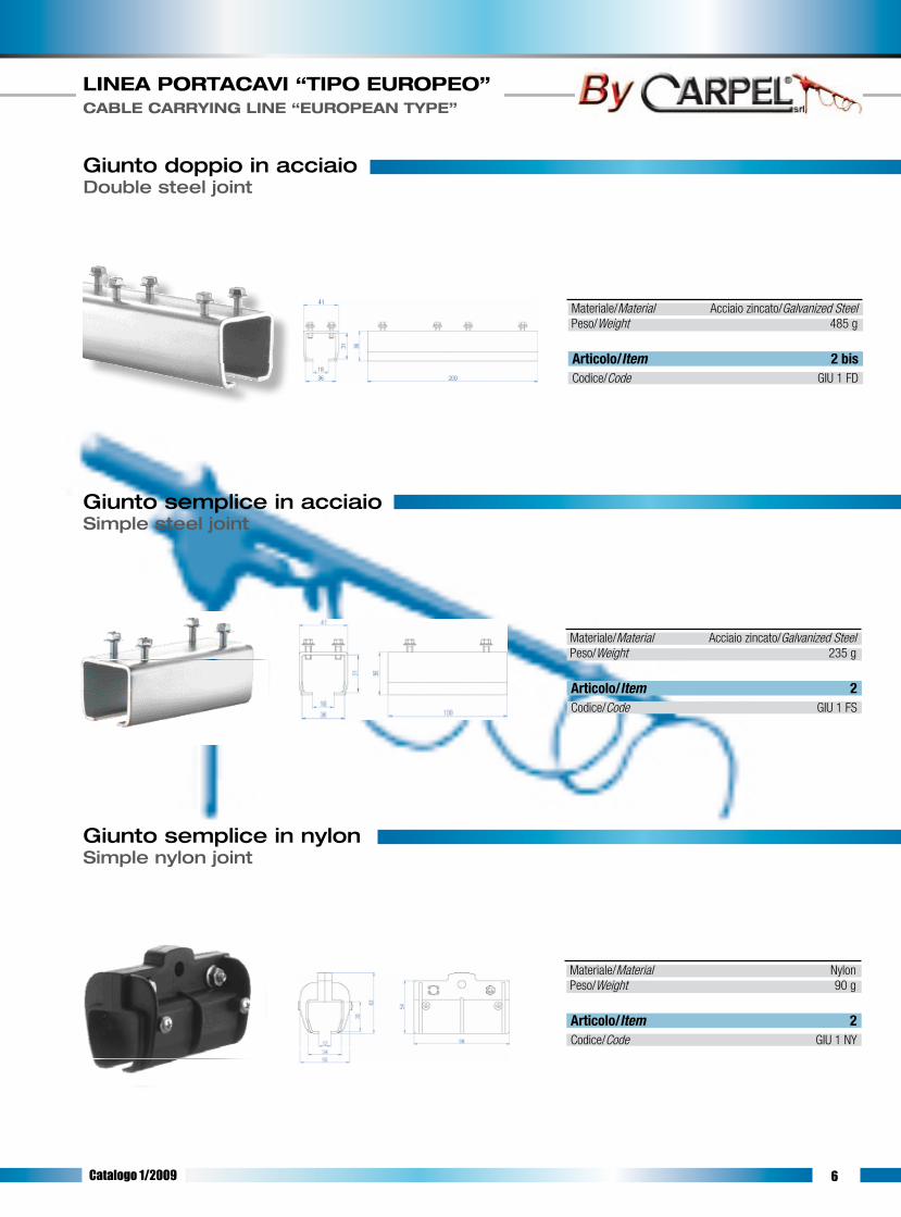
Giunto semplice in acciaioSimple steel joint
Giunto semplice in nylonSimple nylon joint
Giunto doppio in acciaioDouble steel joint
Materiale/Material Acciaio zincato/Galvanized SteelPeso/Weight 485 g
Articolo/Item 2 bisCodice/Code GIU 1 FD
Materiale/Material Acciaio zincato/Galvanized SteelPeso/Weight 235 g
Articolo/Item 2Codice/Code GIU 1 FS
Materiale/Material NylonPeso/Weight 90 g
Articolo/Item 2Codice/Code GIU 1 NY
Catalogo 1/2009

7
LINEA PORTACAVI “TIPO EUROPEO” CABLE CARRYING LINE “EUROPEAN TYPE”
Testata con sellaHead with saddle
TrainoTrailer
Materiale/Material Corpo in nylon/Nylon body Acciaio zincato/Galvanized steelPortata/Capacity 25 kg
Sella/Saddle Peso/Weight Codice/Code Articolo/Item A= 35 mm 155 g TSN1P35 6A= 50 mm 165 g TSN1P50 7A= 65 mm 175 g TSN1P65 8
Sella/Saddle Peso/Weight Codice/Code Articolo/Item A= 35 mm 115 g CRN1P35N 9 A= 50 mm 125 g CRN1P50N 10A= 65 mm 145 g CRN1P65N 11
Sella/Saddle Peso/Weight Codice/Code Articolo/Item A= 35 mm 130 g TRN1P35N 15A= 50 mm 140 g TRN1P50N 16A= 65 mm 160 g TRN1P65N 17
Sella/Saddle Peso/Weight Codice/Code Articolo/Item A= 35 mm 135 g CRN1P35C 12A= 50 mm 145 g CRN1P50C 13A= 65 mm 165 g CRN1P65C 14
Sella/Saddle Peso/Weight Codice/Code Articolo/Item A= 35 mm 165 g TRN1P35C 18A= 50 mm 170 g TRN1P50C 19A= 65 mm 190 g TRN1P65C 20
Carrello portacaviCable carrying trolley
Materiale/Material Corpo in nylon/Nylon body Acciaio zincato/Galvanized steel
Materiale/Material Corpo in nylon/Nylon body Acciaio zincato/Galvanized steel
Ruote Nylon/Nylon Wheels Ø 25 mmPortata/Capacity 15 kg
Ruote Nylon/Nylon Wheels Ø 25 mmPortata/Capacity 10 kg
Cuscinetti rivestiti in nylon/Nylon coated bearing Ø 25 mm
Portata/Capacity 20 kg
Cuscinetti rivestiti in nylon/Nylon coated bearing Ø 25 mmPortata/Capacity 15 kg
Catalogo 1/2009

8
LINEA PORTACAVI “TIPO EUROPEO” CABLE CARRYING LINE “EUROPEAN TYPE”
Testata con sellaHead with saddle
Carrello portacavi Cable carrying trolley
TrainoTrailer
Carrello portacavi - due pezzi Two-piece cable carrying trolley
Sella/Saddle Peso/Weight Codice/Code Articolo/ItemA= 25 mm 265 g TSA 1 P25 60 A= 35 mm 285 g TSA 1 P35 61A= 55 mm 320 g TSA 1 P55 62A= 65 mm 340 g TSA 1 P65 63A= 80 mm 365 g TSA 1 P80 64A= 100 mm 400 g TSA 1 P10 65
Sella/Saddle Peso/Weight Codice/Code Articolo/ItemA= 25 mm 310 g CRA 1 P25C 66A= 35 mm 330 g CRA 1 P35C 67A= 55 mm 365 g CRA 1 P55C 68A= 65 mm 385 g CRA 1 P65C 69A= 80 mm 410 g CRA 1 P80C 70A= 100 mm 445 g CRA 1 P10C 71
Sella/Saddle Peso/Weight Codice/Code Articolo/ItemA= 25 mm 485 g TRA 1 P25C 72A= 35 mm 505 g TRA 1 P35C 73A= 55 mm 540 g TRA 1 P55C 74A= 65 mm 560 g TRA 1 P65C 75A= 80 mm 585 g TRA 1 P80C 76A= 100 mm 620 g TRA 1 P10C 77
Sella/Saddle Peso/Weight Codice/Code Articolo/ItemA= 65 mm 260 g CRD 1 P65C 69 bis
Materiale/Material Acciaio zincato/Galvanized SteelPortata/Capacity 35 kg
Materiale/Material Acciaio zincato/Galvanized SteelRuote/Wheels Cuscinetti acciaio/Steel coated bearings Ø 25 mmPortata/Capacity 30 kg
Materiale/Material Acciaio zincato/Galvanized SteelRuote/Wheels Cuscinetti acciaio/Steel coated bearings Ø 25 mmPortata/Capacity 25 kg
Materiale/Material Acciaio zincato/Galvanized SteelRuote/Wheels Cuscinetti acciaio/Steel coated bearings Ø 25 mmPortata/Capacity 20 kg
Catalogo 1/2009
9
LINEA PORTACAVI “TIPO EUROPEO” CABLE CARRYING LINE “EUROPEAN TYPE”
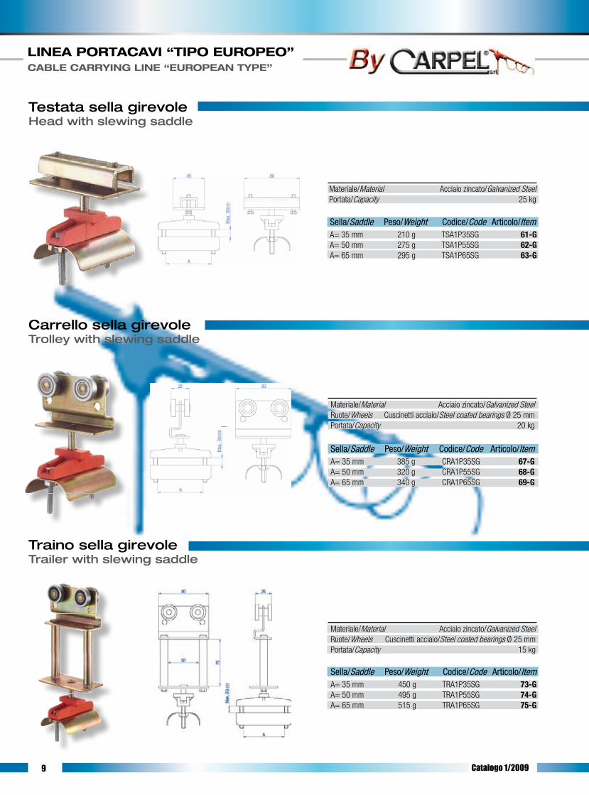
Testata sella girevoleHead with slewing saddle
Carrello sella girevole Trolley with slewing saddle
Traino sella girevoleTrailer with slewing saddle
Sella/Saddle Peso/Weight Codice/Code Articolo/ItemA= 35 mm 210 g TSA1P35SG 61-GA= 50 mm 275 g TSA1P55SG 62-GA= 65 mm 295 g TSA1P65SG 63-G
Materiale/Material Acciaio zincato/Galvanized SteelPortata/Capacity 25 kg
Sella/Saddle Peso/Weight Codice/Code Articolo/ItemA= 35 mm 450 g TRA1P35SG 73-GA= 50 mm 495 g TRA1P55SG 74-GA= 65 mm 515 g TRA1P65SG 75-G
Materiale/Material Acciaio zincato/Galvanized SteelRuote/Wheels Cuscinetti acciaio/Steel coated bearings Ø 25 mm Portata/Capacity 15 kg
Sella/Saddle Peso/Weight Codice/Code Articolo/ItemA= 35 mm 385 g CRA1P35SG 67-GA= 50 mm 320 g CRA1P55SG 68-GA= 65 mm 340 g CRA1P65SG 69-G
Materiale/Material Acciaio zincato/Galvanized SteelRuote/Wheels Cuscinetti acciaio/Steel coated bearings Ø 25 mm Portata/Capacity 20 kg
Catalogo 1/2009

10
LINEA PORTACAVI “TIPO EUROPEO” CABLE CARRYING LINE “EUROPEAN TYPE”
Testata con morsettoHead with clamp
Carrello con morsettoTrolley with clamp
Traino con morsettoTrailer with clamp
Articolo/Item 42Codice/Code TSN 1 M22
Articolo/Item 45 46Codice/Code CRN 1 M22N CRN 1 M22C
Articolo/Item 47 48Codice/Code TRN 1 M22N TRN 1 M22C
Materiale/Material Acciaio zincato/Galvanized SteelPortata/Capacity 30 kgA (Ø max cavo/Cable max) 22 mmPeso/Weight 205 g
Materiale/Material Corpo in nylon/Nylon body Minuterie in acciaio zincato/Small parts in galvanized steelRuote/Wheels Nylon Ø 25 mm Cuscinetti rivestiti nylon/Nylon coated bearings Ø 25 mmA (Ø max cavo/Cable max) 22 mm Ruote nylon Ruote cuscinetto Nylon wheels Wheels with bearingPeso/Weight 390 g 415 gPortata/Capacity 15 kg 20 kg
Catalogo 1/2009
Materiale/Material Corpo in nylon/Nylon body Minuterie in acciaio zincato/Small parts in galvanized steelRuote/Wheels Nylon Ø 25 mm Cuscinetti rivestiti nylon/Nylon coated bearings Ø 25 mmPortata/Capacity 20 kg
A (Ø max cavo/Cable max) 22 mm Ruote nylon Ruote cuscinetto Nylon wheels Wheels with bearingPeso/Weight 130 g 150 g

11
LINEA PORTACAVI “TIPO EUROPEO” CABLE CARRYING LINE “EUROPEAN TYPE”
Connettore per cavo piatto - presa tipo CARPELConnector for flat cable - socket type CARPEL
Connettore per cavo piatto - presa tipo STANDARDConnector for flat cable - socket type STANDARD
Connettore per cavo tondo - presa tipo STANDARDConnector for round cable - socket type STANDARD
Articolo/Item 015 030 040Codice/Code CON 1 P10 CON 1 P16 CON 1 P24
10 Poli/Pole 16 Poli/Pole 24 Poli/Pole
Materiale/Material Piastra in alluminio/Alluminium plate Presa in nylon/Nylon socket Stecca in acciaio zincato/Galvanized steel slat Minuteria in acciaio zincato/Small parts in galvanized steelRuote/Wheels Cuscinetti acciaio/Steel coated bearings Ø 25 mm Portata/Capacity 35 kgPeso/Weight 2900 g
Articolo/Item 026 027 028 029Codice/Code CON 1 P10I CON 1 P16I CON 1 P24I CON 1 P32I
10 Poli/Pole 16 Poli/Pole 24 Poli/Pole 32 Poli/Pole
Materiale/Material Piastra in alluminio/Alluminium plate Presa in alluminio/Alluminium socket Stecca in acciaio zincato/Galvanized steel slat Minuteria in acciaio zincato/Small parts in galvanized steelRuote/Wheels Cuscinetti acciaio/Steel coated bearings Ø 25 mm Portata/Capacity 35 kgPeso/Weight 2660 g
Articolo/Item 005 010 020 025Codice/Code CON 1 T10 CON 1 T16 CON 1 T24 CON 1 T32
10 Poli/Pole 16 Poli/Pole 24 Poli/Pole 32 Poli/Pole
Materiale/Material Piastra in alluminio/Alluminium plate Presa in alluminio/Alluminium socket Stecca in acciaio zincato/Galvanized steel slat Minuteria in acciaio zincato/Small parts in galvanized steelRuote/Wheels Cuscinetti acciaio/Steel coated bearings Ø 25 mm Portata/Capacity 35 kgPeso/Weight 2885 g
Catalogo 1/2009
12
LINEA PORTACAVI “TIPO EUROPEO” CABLE CARRYING LINE “EUROPEAN TYPE”
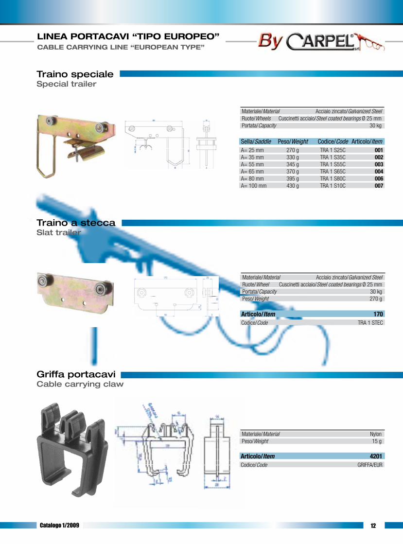
Traino specialeSpecial trailer
Traino a steccaSlat trailer
Griffa portacaviCable carrying claw
Sella/Saddle Peso/Weight Codice/Code Articolo/ItemA= 25 mm 270 g TRA 1 S25C 001A= 35 mm 330 g TRA 1 S35C 002A= 55 mm 345 g TRA 1 S55C 003A= 65 mm 370 g TRA 1 S65C 004A= 80 mm 395 g TRA 1 S80C 006A= 100 mm 430 g TRA 1 S10C 007
Materiale/Material Acciaio zincato/Galvanized SteelRuote/Wheels Cuscinetti acciaio/Steel coated bearings Ø 25 mmPortata/Capacity 30 kg
Articolo/Item 170Codice/Code TRA 1 STEC
Materiale/Material Acciaio zincato/Galvanized SteelRuote/Wheel Cuscinetti acciaio/Steel coated bearings Ø 25 mmPortata/Capacity 30 kgPeso/Weight 270 g
Articolo/Item 4201Codice/Code GRIFFA/EUR
Materiale/Material NylonPeso/Weight 15 g
Catalogo 1/2009

13 Catalogo 1/2009

14
ISTRUZIONI DI MONTAGGIO - linea con traino -ASSEMBLY INSTRUCTIONS - line with trailer -
1- Posizionare le sospensioni nelle proprie sedi (pareti o mensole); in questa fase di montaggio non bisogna stringere eccessivamente le viti delle sospensioni, in modo da permettere l’inserimento delle barre di canalina ed il loro eventuale posizionamento. 2- Inserire le barre di canalina nelle sospensioni; verificare la presenza di un numero adeguato di sospensioni su tutta la linea. In questa fase è necessario prestare particolare attenzione allo “spigolo vivo” del taglio della canalina: tale spigolo è necessario per un corretto allineamento delle parti di canalina da unire e per far scorrere correttamente il carrello all’interno. 3- Applicare i giunti alle estremità delle barre, quindi serrare le viti senza deformare la canalina. Le estremità delle canaline devono essere adiacenti e ben allineate (la conformazione del giunto impedisce il non allineamento delle canaline) onde evitare che il carrello durante la corsa urti contro l’estremità della canalina e che, con il passare del tempo, sia pregiudicato il buon funzionamento del carrello stesso. 4- Serrare tutte le viti delle sospensioni verificando nel medesimo tempo il bloccaggio dell’intera linea. 5- Verificare l’allineamento dell’intera linea. 6- Inserire la prima testata (senza sella) e fissarla all’estremità opposta a quella in cui la linea si allaccerà all’alimentazione. 7- Inserire il traino nella canalina nell’estremità senza testata. 8- Di seguito, nello stesso modo, inserire tutti i carrelli che sosterranno il cavo di alimentazione 9- Posizionare la testata rimanente (con sella) e fissarla in modo da chiudere la linea. La chiusura della linea impedisce la fuoriuscita del traino e dei carrelli. 10- Inserire il cavo conduttore nel carrello, tra sella e controsella, partendo dalla testata con la sella sino ad arrivare al traino.11- Stringere le viti del carrello, fissando il cavo tra sella e controsella, avendo cura di verificare che non sia presente alcun movimento di scorrimento del cavo nel carrello. 12- Lasciare tra carrello e carrello una quantità di cavo pari all’ansa desiderata.
1- Place the suspensions into their seats (walls or brackets), without overtightening the suspension screws so as to allow the raceway bars to be inserted and positioned, if necessary. 2- Insert the raceway bars into the suspensions; be sure that a proper number of suspensions are all over the line. In this phase particular attention has to be paid to the “sharp edge” of the raceway cutting side: such an edge is required to properly align the raceway parts to be connected and for the trolley to properly slide inside. 3- Apply the joints to the bar ends, then tighten the screws without deforming the raceway. The raceway ends must be adjacent and well aligned (the joint configu-ration avoids the raceway misalignment) preventing the trolley to strike the raceway ends during its stroke and the trolley to properly work in the time. 4- Tighten all the suspension screws while checking that all the line is locked. 5- Verify that all the line is properly aligned. 6- Insert the first head (without the saddle), fixing it at the end opposite to that where the line will be connected to the feeding line. 7- Insert the trailer into the raceway at the headless end. 8- Insert now all the trolleys that will have to carry the feeding cable, proceeding the same way as above. 9- Position the remaining head (with the saddle) and fix it in such a way that the line is closed. The line closing prevents the trailer and the trolleys to come out. 10- Insert the conductor cable into the trolley, between the saddle and the countersaddle. Start inserting the saddle from the head until reaching the trailer. 11- Tighten the trolley screws fixing the cable between the saddle and the countersaddle, paying attention to as the cable into the trolley does not slide at alI. 12- Leave a quantity of cable between each trolley equal to the required loop.
LINEA PORTACAVI “TIPO EUROPEO” CABLE CARRYING LINE “EUROPEAN TYPE”
Catalogo 1/2009

15
LINEA PORTACAVI “TIPO EUROPEO” CABLE CARRYING LINE “EUROPEAN TYPE”
ISTRUZIONI DI MONTAGGIO - linea con pulsantiera -ASSEMBLY INSTRUCTIONS - line with push-button panel -
Nel caso si debba montare la linea di azionamento comandi, il procedimento è simile al precedente, avendo però l’accortezza di inserire al posto del traino (prece-dente punto 7) il connettore. Il montaggio del connettore avviene nel modo seguente. 1- Preparare il cavo piatto montato sulla linea, eliminando 3 cm circa di guaina esterna e 1 cm circa di guaina per ogni singolo cavetto interno. 2- Far passare il cavo piatto tra la sella e la piastra del connettore. 3- Aprire il connettore: se si tratta di connettore in nylon (nei colori: arancio, azzurro o giallo), fare leva sull’estremità della molla mediante un utensile (pinza o cacciavite); se si tratta di connettore metallico, premere le due leve esterne in modo da liberare l’aggancio. Rimuovere quindi il coperchio. 4- Prendere i frutti all’interno del connettore e separarli, nel caso non lo fossero già. 5- Far passare il cavo piatto attraverso il pressacavo posto sulla base del connettore. 6- Connettere il cavo piatto della linea al frutto femmina (frutto senza i pioli di contatto esterni), inserendo i singoli cavetti nelle apposite sedi numerate e serrando le viti relative a ogni sede per bloccare il cavo. La sequenza di connessione dei cavi è a cura dell’installatore a seconda delle proprie esigenze. 7- Inserire il frutto femmina nella base del connettore bloccandolo mediante le quattro viti poste agli angoli. 8- Serrare le viti del pressacavo sulla base del connettore onde evitare l’ingresso di polvere o altro. 9- Serrare le viti della sella lasciando abbondante il cavo tra la sella e il pressacavo. 10- Far passare il cavo tondo della pulsantiera attraverso il pressacavo del coperchio del connettore, dopo aver separato, per circa 40-50 cm, il cavo stesso dai cavetti metallici laterali. 11- Eliminare le guaine come indicato per il cavo piatto e connettere il cavo tondo al frutto maschio (quello con i pioli di contatto esterni), avendo cura di seguire le istruzioni date per il frutto femmina e seguendo lo stesso ordine di connessione. 12- Fissare il frutto maschio al coperchio del connettore utilizzando le quattro viti poste agli angoli dello stesso. 13- Applicare il coperchio del connettore alla base, avendo cura di far coincidere i due frutti, quindi serrarlo utilizzando le leve, per i connettori di tipo STANDARD, o la molla, per connettore tipo CARPEL in nylon. 14- Far compiere al cavo tondo un giro completo, quindi fissare un cavetto laterale a ciascun tirante della piastra. 15- Per mezzo di una fascetta fissare i cavetti laterali metallici al cavo tondo nel punto in cui questi si incontrano, evitando così che durante l’utilizzo i cavetti laterali si separino ulteriormente dal cavo tondo. 16- Fissare ad un cavetto laterale il cavo tondo per mezzo di una fascetta in un punto del giro a vuoto del cavo. Questa operazione, unita a lasciare un giro a vuoto di cavo, è necessaria per evitare che durante l’utilizzo il tiro sul cavo vada a ripercuotersi sui contatti all’interno del connettore, anziché distribuirsi sui cavetti metallici. 17- Serrare il pressacavo posto sul coperchiO del connettore girando la vite del pressacavo stesso al fine di evitare l’ingresso di polvere o altro.
Should the drive controls line be installed, the process is similar to the previous one but the connector must be inserted instead of the trailer (see previous point 7). Install the connector as follows: 1- Mount the flat cable on the line and remove approx. 3 cm of external sheath and approx. 1 cm of sheath for each inside wire. 2- Run the flat cable between the saddle and the connector plate. 3- Open the connector: should it be a nylon one (orange, light blue or yellow coloured) lever, by a pro per tool (pliers or screwdriver), the spring end. Should it be a metal connector, press the two external levers for releasing the coupling. Remove the cover. 4- Take the contact blocks inside the connector. Separate them, if necessary. 5- Run the flat cable through the cable gland placed on the connector base. 6- Connect the line flat cable to the female contact block (contact block without the external contact pins) by inserting the single wires into the proper numbered seats. Fix the cable by tightening the relevant screws to each seat. The cable connection sequence is provided by the installer according to his own requirements. 7- Insert the female contact block into the connector base and lock it by the four screws placed at the edges. 8- Tighten the cable gland screws to the connector base, thus preventing any dust or other foreign matters to enter. 9- Tighten the saddle screws paying attention to leave a big quantity of cable between the saddle and the cable gland. 10- After separating the round cable from the side metal wires for approx. 40-50 cm, run the round cable of the push-button panel through the cable gland of the connector cover. 11- Remove the sheaths as described for the flat cable and connect the round cable to the male contact block (the one provided with the external contact pins), paying attention to follow the instructions and proceeding in the same order as done for the female contact block. 12- Fix the male contact block to the connector cover using the four screws placed on the cover edges. 13- Apply the connector cover to the base matching the two contact blocks, then tighten it with the levers for STANDARD connectors, or with the spring for the CARPEL nylon connector. 14- Be sure the round cable completes an entire revolution, then fix a side wire to each tie rod plate. 15- Fix the metal side wires to the round cable at the point where they meet, using a proper fastening clamp, thus avoiding the side wires to be further separated from the round cable during the operation. 16- Fix the round cable to a side wire using a proper fastening clamp in a point where the cable is idle running. This operation, besides assuring a cable idle running, is required to prevent the cable traction affecting the contacts inside the connector during the operations, instead of distributing on the metal wires. 17- Tighten the cable gland placed on the connector cover by turning the cable gland screw, thus avoiding any dust or other foreign matters to enter.
Catalogo 1/2009

16

17
LINEA PORTACAVI “TIPO 2000” CABLE CARRYING LINE “TYPE 2000”
La linea portacavi tipo 2000 è un sistema pratico, efficiente e sicuro per
la distribuzione dell’energia, sia essa elettrica, pneumatica o altro, per
apparecchi mobili quali gru, carri ponti etc.
In questo catalogo troverete sicuramente la soluzione più adatta al vo-
stro problema potendo scegliere tra più linee di carrelli portacavi tutti
normalizzati per scorrere in maniera sicura, efficiente e duratura all’in-
terno della canalina di nostra produzione.
Qualunque sia la scelta da voi operata, sarà una scelta di qualità e
sicurezza in quanto su tutte le linee troverete apposto il marchio ”CE“ a
garanzia che i nostri prodotti rispondono ai requisiti dettati dalla Diret-
tiva Macchine 89/932 CEE e successivi emendamenti.
The cable carrying line type “2000” is a handy, efficient and safe sy-
stem for electrical, pneumatic and other energy distribution to mobile
equipment such as cranes, overhead traveling cranes, etc.
This catalogue includes various cable carrying lines; among them you
will surely find the most suitable to your requirements. You may cho-
ose among several lines of cable carrying trolleys, all of them being
standardized for assuring a safe, efficient and lasting sliding operation
inside our cable raceway.
Regardless of your choice, it will assure you quality and safety; al-
lour lines have been labelled with the “CE” mark, to guarantee that
our products meet the 89/932/EEC Machinery Directive and further
amendments.
Ci riserviamo la facoltà di apportare, senza alcun preavviso, modifiche costruttive al fine
di migliorare le qualità tecniche, funzionali ed estetiche del prodotto.
We reserve the right to make modifications in order to improve the technical, functional
and aesthetical qualities of our products without any prior notice.
Catalogo 2/2009

18
LINEA PORTACAVI “TIPO 2000” CABLE CARRYING LINE “TYPE 2000”
Canalina PortacavoCable carrying raceway
Testata semplice in nylonNylon simple head
Testata semplice in acciaioSteel simple head
Materiale/Material Acciaio zincato/Galvanized Steel Acciao inox/Stainless steelSpessore/Thickness 1,5 mmMomento d’inerzia/Moment of inertia 6,7 cm4
Momento resistente/Resisting moment 3,1 cm3
Peso/Weight 2 kg/mDistanza sospensioni/Suspension distance 2 mPortata/Capacity 40 kg ogni/every 1,5 m
Articolo/Item 06Codice/Code TS 2 SEMPNCodice/Code TS 2 SEMPN I
Materiale/Material Corpo in nylon/Nylon body Acciaio zincato o inox/Galvanized steel or stainless steelPeso/Weight 70 g
Materiale/Material Acciaio zincato/Galvanized Steel Acciao inox/Stainless steelPeso/Weight 175 g
Articolo/Item 06Codice/Code TS 2 SEMPACodice/Code TS 2 SEMPA I
Articolo/Item 1Codice barre/Bar code 3 CAN 2000 3Codice barre/Bar code 3 m INOX CAN 3M INOXCodice barre/Bar code 4 CAN 2000 4Codice barre/Bar code 5 CAN 2000 5Codice barre/Bar code 6 CAN 2000 6
Catalogo 2/2009

19
LINEA PORTACAVI “TIPO 2000” CABLE CARRYING LINE “TYPE 2000”
Sospensione con fissaggio lateraleSuspension with side fixing
Sospensione con fissaggio a pareteSuspension with wall fixing
Sospensione a parete con fissaggio di tipo compostoWall suspension with built-up fixing system
Materiale/Material Acciaio zincato/Galvanized Steel Acciao inox/Stainless steel
con viti senza viti with screws without screwsPeso/Weight 240 g 180 gPortata/Capacity 35 kg 35 kg
Materiale/Material Acciaio zincato/Galvanized Steel Acciao inox/Stainless steel
con viti senza viti with screws without screwsPeso/Weight 180 g 135 gPortata/Capacity 50 kg 50 kg
Articolo/Item 05+05/CCodice/Code SOS 2 PATC
Materiale/Material Acciaio zincato/Galvanized Steel Peso/Weight 195 gPortata/Capacity 50 kg
Articolo/Item 04 05Codice/Code SOS 2 FLCV SOS 2 FLSVCodice/Code SOS 2 FLCV I SOS 2 FLSV I
Articolo/Item 05+05 05+05Codice/Code SOS 2 PACV SOS 2 PASVCodice/Code SOS 2 PACV I SOS 2 PASV I
Catalogo 2/2009

20
LINEA PORTACAVI “TIPO 2000” CABLE CARRYING LINE “TYPE 2000”
Giunto doppio in acciaioDouble steel joint
Giunto semplice in acciaioSimple steel joint
Materiale/Material Acciaio zincato/Galvanized Steel Acciaio inox/Stainless steelPeso/Weight 520 g
Materiale/Material Acciaio zincato/Galvanized Steel Acciaio inox/Stainless steelPeso/Weight 260 g
Articolo/Item 03Codice/Code GIU 2 FDCodice/Code GIU 2 FD I
Articolo/Item 02Codice/Code GIU 2 FSCodice/Code GIU 2 FS I
Catalogo 2/2009

21
LINEA PORTACAVI “TIPO 2000” CABLE CARRYING LINE “TYPE 2000”
Testata con sellaHead with saddle
TrainoTrailer
Materiale/Material Corpo in nylon/Nylon body Min. in acciaio zinc. o inox/Small parts in galvanized steel or stainless steelPortata/Capacity 30 kg
Sella/Saddle Peso/Weight Codice/Code Articolo/Item A= 35 mm 150 g TSN2P35 301A= 50 mm 165 g TSN2P50 302A= 65 mm 175 g TSN2P65 303A= 65 mm 175 g TSN2P65I 303
Sella/Saddle Peso/Weight Codice/Code Articolo/Item A= 35 mm 140 g CRN2P35N 321 A= 50 mm 150 g CRN2P50N 322A= 65 mm 160 g CRN2P65N 323A= 65 mm 160 g CRN2P65NI 323
Sella/Saddle Peso/Weight Codice/Code Articolo/Item A= 35 mm 160 g TRN2P35N 331A= 50 mm 170 g TRN2P50N 332A= 65 mm 180 g TRN2P65N 333A= 65 mm 180 g TRN2P65NI 333
Sella/Saddle Peso/Weight Codice/Code Articolo/Item A= 35 mm 215 g CRN2P35C 351A= 50 mm 230 g CRN2P50C 352A= 65 mm 240 g CRN2P65C 353A= 65 mm 240 g CRN2P65CI 353
Sella/Saddle Peso/Weight Codice/Code Articolo/Item A= 35 mm 235 g TRN2P35C 341A= 50 mm 245 g TRN2P50C 342A= 65 mm 260 g TRN2P65C 343A= 65 mm 260 g TRN2P65C I 343
Carrello portacaviCable carrying trolley
Materiale/Material Corpo in nylon/Nylon body Min. in acciaio zinc. o inox/Small parts in galvanized steel or stainless steel
Materiale/Material Corpo in nylon/Nylon body Min. in acciaio zinc. o inox/Small parts in galvanized steel or stainless steel
Ruote Nylon/Nylon Wheels Ø 33 mmPortata/Capacity 20 kg
Ruote Nylon/Nylon Wheels Ø 33 mmPortata/Capacity 15 kg
Cuscinetti rivestiti in nylon/Nylon coated bearing Ø 32 mmPortata/Capacity 25 kg
Cuscinetti rivestiti in nylon/Nylon coated bearing Ø 32 mmPortata/Capacity 20 kg
Catalogo 2/2009
22
LINEA PORTACAVI “TIPO 2000” CABLE CARRYING LINE “TYPE 2000”
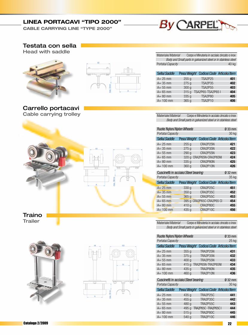
Testata con sellaHead with saddle
TrainoTrailer
Carrello portacaviCable carrying trolley
Materiale/Material Corpo e Minuteria in acciaio zincato o inox Body and Small parts in galvanized steel or in stainless steelPortata/Capacity 40 kg
Sella/Saddle Peso/Weight Codice/Code Articolo/Item A= 25 mm 255 g TSA2P25 401A= 35 mm 275 g TSA2P35 402A= 55 mm 300 g TSA2P55 403A= 65 mm 315 g TSA2P65-TSA2P65 I 404A= 80 mm 335 g TSA2P80 405A= 100 mm 365 g TSA2P10 406
Sella/Saddle Peso/Weight Codice/Code Articolo/Item A= 25 mm 330 g CRA2P25C 451A= 35 mm 350 g CRA2P35C 452A= 55 mm 365 g CRA2P55C 453A= 65 mm 395 g CRA2P65C-CRA2P65 CI 454A= 80 mm 410 g CRA2P80C 455A= 100 mm 435 g CRA2P10C 456
Sella/Saddle Peso/Weight Codice/Code Articolo/Item A= 25 mm 255 g CRA2P25N 421A= 35 mm 275 g CRA2P35N 422A= 55 mm 290 g CRA2P55N 423A= 65 mm 320 g CRA2P65N-CRA2P65NI 424A= 80 mm 335 g CRA2P80N 425A= 100 mm 360 g CRA2P10N 426
Materiale/Material Corpo e Minuteria in acciaio zincato o inox Body and Small parts in galvanized steel or in stainless steel
Ruote Nylon/Nylon Wheels Ø 33 mmPortata/Capacity 30 kg
Cuscinetti in acciaio/Steel bearing Ø 32 mmPortata/Capacity 35 kg
Sella/Saddle Peso/Weight Codice/Code Articolo/Item A= 25 mm 435 g TRA2P25C 441A= 35 mm 455 g TRA2P35C 442A= 55 mm 480 g TRA2P55C 443A= 65 mm 495 g TRA2P65C -TRA2P65C I 444A= 80 mm 515 g TRA2P80C 445A= 100 mm 540 g TRA2P10C 446
Sella/Saddle Peso/Weight Codice/Code Articolo/Item A= 25 mm 355 g TRA2P25N 431A= 35 mm 375 g TRA2P35N 432A= 55 mm 400 g TRA2P55N 433A= 65 mm 415 g TRA2P65N-TRA2P65NI 434A= 80 mm 435 g TRA2P80N 435A= 100 mm 460 g TRA2P10N 436
Materiale/Material Corpo e Minuteria in acciaio zincato o inox Body and Small parts in galvanized steel or in stainless steel
Ruote Nylon/Nylon Wheels Ø 33 mmPortata/Capacity 25 kg
Cuscinetti in acciaio/Steel bearing Ø 32 mmPortata/Capacity 30 kg
Catalogo 2/2009

23
LINEA PORTACAVI “TIPO 2000” CABLE CARRYING LINE “TYPE 2000”
Testata sella girevoleHead with slewing saddle
Carrello sella girevole Trolley with slewing saddle
Traino sella girevoleTrailer with slewing saddle
Sella/Saddle Peso/Weight Codice/Code Articolo/ItemA= 35 mm 315 g TSA2P35SG 402-GA= 50 mm 340 g TSA2P55SG 403-GA= 65 mm 355 g TSA2P65SG 404-G
Materiale/Material Acciaio zincato/Galvanized SteelPortata/Capacity 30 kg
Sella/Saddle Peso/Weight Codice/Code Articolo/ItemA= 35 mm 490 g TRA2P35SG 442-GA= 50 mm 505 g TRA2P55SG 443-GA= 65 mm 535 g TRA2P65SG 444-G
Materiale/Material Acciaio zincato/Galvanized SteelRuote/Wheels Cuscinetti acciaio/Steel beraings Ø 32 mm Portata/Capacity 20 kg
Sella/Saddle Peso/Weight Codice/Code Articolo/ItemA= 35 mm 390 g CRA2P35SG 452-GA= 50 mm 405 g CRA2P55SG 453-GA= 65 mm 435 g CRA2P65SG 454-G
Materiale/Material Acciaio zincato/Galvanized SteelRuote/Wheels Cuscinetti acciaio/Steel beraings Ø 32 mm Portata/Capacity 25 kg
Catalogo 2/2009

24
LINEA PORTACAVI “TIPO 2000” CABLE CARRYING LINE “TYPE 2000”
Testata con morsettoHead with clamp
Carrello con morsettoTrolley with clamp
Traino con morsettoTrailer with clamp
Articolo/Item 602Codice/Code TSA 2 M22
Articolo/Item 603 604Codice/Code CRA 2 M22N CRA 2 M22C
Articolo/Item 631 632Codice/Code TRA 2 M22N TRA 2 M22C
Materiale/Material Acciaio zincato/Galvanized SteelPortata/Capacity 30 kgA (Ø max cavo/Cable max) 22 mmPeso/Weight 205 g
Materiale/Material Acciaio zincato/Galvanized SteelRuote/Wheels Nylon Ø 33 mm Cuscinetti acciaio/Steel bearings Ø 32 mmA (Ø max cavo/Cable max) 22 mm Ruote nylon Ruote cuscinetto Nylon wheels Wheels with bearingPeso/Weight 195 g 270 gPortata/Capacity 20 kg 25 kg
Materiale/Material Acciaio zincato/Galvanized SteelRuote/Wheels Nylon Ø 33 mm Cuscinetti acciaio/Steel bearings Ø 32 mmA (Ø max cavo/Cable max) 22 mm Ruote nylon Ruote cuscinetto Nylon wheels Wheels with bearingPeso/Weight 380 g 455 gPortata/Capacity 15 kg 20 kg
Catalogo 2/2009

25
LINEA PORTACAVI “TIPO 2000” CABLE CARRYING LINE “TYPE 2000”
Connettore per cavo piatto - presa tipo CARPELConnector for flat cable - socket type CARPEL
Connettore per cavo piatto - presa tipo STANDARDConnector for flat cable - socket type STANDARD
Connettore per cavo tondo - presa tipo STANDARDConnector for round cable - socket type STANDARD
Articolo/Item 1029 1030 1031 1032Codice/Code CON 2 P10I CON 2 P16I CON 2 P24I CON 2 P32I
10 Poli/Pole 16 Poli/Pole 24 Poli/Pole 32 Poli/Pole
Articolo/Item 1019 1020 1021 1022Codice/Code CON 2 T10 CON 2 T16 CON 2 T24 CON 2 T32
10 Poli/Pole 16 Poli/Pole 24 Poli/Pole 32 Poli/Pole
Articolo/Item 1009 1010 1011Codice/Code CON 2 P10 CON 2 P16 CON 2 P24
10 Poli/Pole 16 Poli/Pole 24 Poli/Pole
Materiale/Material Piastra in alluminio/Alluminium plate Presa in nylon/Nylon socket Stecca in acciao zincato/Galvanized steel slat Minuteria in acciaio zincato/Small parts in galvanized steelRuote/Wheels Cuscinetti acciaio/Steel bearings Ø 32 mm Portata/Capacity 40 kgPeso/Weight 2900 g
Materiale/Material Piastra in alluminio/Alluminium plate Presa in alluminio/Alluminium socket Stecca in acciao zincato/Galvanized steel slat Minuteria in acciaio zincato/Small parts in galvanized steelRuote/Wheels Cuscinetti acciaio/Steel bearings Ø 32 mm Portata/Capacity 40 kgPeso/Weight 2660 g
Materiale/Material Piastra in alluminio/Alluminium plate Presa in alluminio/Alluminium socket Stecca in acciao zincato/Galvanized steel slat Minuteria in acciaio zincato/Small parts in galvanized steelRuote/Wheels Cuscinetti acciaio/Steel bearings Ø 32 mm Portata/Capacity 40 kgPeso/Weight 2885 g
Catalogo 2/2009

26
LINEA PORTACAVI “TIPO 2000” CABLE CARRYING LINE “TYPE 2000”
Traino speciale Special trailer
Traino con sella centraleTrailer with central saddle
Griffa portacaviCable carrying claw
Ruote Nylon/Nylon Wheels Ø 33 mmPortata/Capacity 35 kg
Materiale/Material Acciaio zincato/Galvanized Steel
Sella/Saddle Peso/Weight Codice/Code Articolo/Item A= 25 mm 695 g TRP2P25N RN25A= 40 mm 735 g TRP2P40N RN40A= 55 mm 765 g TRP2P55N RN55A= 65 mm 785 g TRP2P65N RN65A= 85 mm 855 g TRP2P85N RN85A= 100 mm 890 g TRP2P10N RN10
Sella/Saddle Peso/Weight Codice/Code Articolo/Item A= 25 mm 765 g TRP2P25C RC25A= 40 mm 805 g TRP2P40C RC40A= 55 mm 835 g TRP2P55C RC55A= 65 mm 855 g TRP2P65C RC65A= 85 mm 925 g TRP2P85C RC85A= 100 mm 960 g TRP2P10C RC10
Materiale/Material Acciaio zincato/Galvanized SteelRuote/Wheels Cuscinetti acciaio/Steel bearings Ø 32 mm Portata/Capacity 35 kg
Sella/Saddle Peso/Weight Codice/Code Articolo/Item A= 25 mm 545 g TR2SCS25 225A= 35 mm 585 g TR2SCS35 235A= 55 mm 615 g TR2SCS55 255A= 65 mm 635 g TR2SCS65 265A= 85 mm 705 g TR2SCS85 280A= 100 mm 740 g TR2SCS10 210
Materiale/Material NylonPeso/Weight 20 g
Cuscinetti in acciaio/Steel bearing Ø 32 mmPortata/Capacity 40 kg
Articolo/Item 4202Codice/Code GRIFFA/2000
Catalogo 2/2009

27 Catalogo 2/2009

28
ISTRUZIONI DI MONTAGGIO - linea con traino -ASSEMBLY INSTRUCTIONS - line with trailer -
1- Posizionare le sospensioni nelle proprie sedi (pareti o mensole); in questa fase di montaggio non bisogna stringere eccessivamente le viti delle sospensioni, in modo da permettere l’inserimento delle barre di canalina ed il loro eventuale posizionamento. 2- Inserire le barre di canalina nelle sospensioni; verificare la presenza di un numero adeguato di sospensioni su tutta la linea. In questa fase è necessario prestare particolare attenzione allo “spigolo vivo” del taglio della canalina: tale spigolo è necessario per un corretto allineamento delle parti di canalina da unire e per far scorrere correttamente il carrello all’interno. 3- Applicare i giunti alle estremità delle barre, quindi serrare le viti senza deformare la canalina. Le estremità delle canaline devono essere adiacenti e ben allineate (la conformazione del giunto impedisce il non allineamento delle canaline) onde evitare che il carrello durante la corsa urti contro l’estremità della canalina e che, con il passare del tempo, sia pregiudicato il buon funzionamento del carrello stesso. 4- Serrare tutte le viti delle sospensioni verificando nel medesimo tempo il bloccaggio dell’intera linea. 5- Verificare l’allineamento dell’intera linea. 6- Inserire la prima testata (senza sella) e fissarla all’estremità opposta a quella in cui la linea si allaccerà all’alimentazione. 7- Inserire il traino nella canalina nell’estremità senza testata. 8- Di seguito, nello stesso modo, inserire tutti i carrelli che sosterranno il cavo di alimentazione 9- Posizionare la testata rimanente (con sella) e fissarla in modo da chiudere la linea. La chiusura della linea impedisce la fuoriuscita del traino e dei carrelli. 10- Inserire il cavo conduttore nel carrello, tra sella e controsella, partendo dalla testata con la sella sino ad arrivare al traino. 11- Stringere le viti del carrello, fissando il cavo tra sella e controsella, avendo cura di verificare che non sia presente movimento di scorrimento del cavo nel carrello. 12- Lasciare tra carrello e carrello una quantità di cavo pari all’ansa desiderata.
1- Place the suspensions into their seats (walls or brackets), without overtightening the suspension screws so as to allow the raceway bars to be inserted and positioned, if necessary. 2- Insert the raceway bars into the suspensions; be sure that a proper number of suspensions are all over the line. In this phase particular attention has to be paid to the “sharp edge” of the raceway cutting side: such an edge is required to properly align the raceway parts to be connected and for the trolley to properly slide inside. 3- Apply the joints to the bar ends, then tighten the screws without deforming the raceway. The raceway ends must be adjacent and well aligned (the joint configu-ration avoids the raceway misalignment) preventing the trolley to strike the raceway ends during its stroke and the trolley to properly work in the time. 4- Tighten all the suspension screws while checking that all the line is locked. 5- Verify that all the line is properly aligned. 6- Insert the first head (without the saddle), fixing it at the end opposite to that where the line will be connected to the feeding line. 7- Insert the trailer into the raceway at the headless end. 8- Insert now all the trolleys that will have to carry the feeding cable, proceeding the same way as above. 9- Position the remaining head (with the saddle) and fix it in such a way that the line is closed. The line closing prevents the trailer and the trolleys to come out. 10- Insert the conductor cable into the trolley, between the saddle and the countersaddle. Start inserting the saddle from the head until reaching the trailer. 11- Tighten the trolley screws fixing the cable between the saddle and the countersaddle, paying attention so as the cable into the trolley does not slide at alI. 12- Leave a quantity of cable between each trolley equal to the required loop.
LINEA PORTACAVI “TIPO 2000” CABLE CARRYING LINE “TYPE 2000”
Catalogo 2/2009

29
LINEA PORTACAVI “TIPO 2000” CABLE CARRYING LINE TYPE “2000”
ISTRUZIONI DI MONTAGGIO - linea con pulsantiera -ASSEMBLY INSTRUCTIONS - line with push-button panel -
Nel caso si debba montare la linea di azionamento comandi il procedimento è simile al precedente, avendo però l’accortezza di inserire al posto del traino (prece-dente punto 7) il connettore. Il montaggio del connettore avviene nel modo seguente: 1- Preparare il cavo piatto montato sulla linea, eliminando 3 cm circa di guaina esterna e 1 cm circa di guaina per ogni singolo cavetto interno. 2- Far passare il cavo piatto tra la sella e la piastra del connettore. 3- Aprire il connettore: se si tratta di connettore in nylon (nei colori: arancio, azzurro o giallo), fare leva sull’estremità della molla mediante un utensile (pinza o cacciavite); se si tratta di connettore metallico, premere le due leve esterne in modo da liberare l’aggancio. Rimuovere quindi il coperchio. 4- Prendere i frutti all’interno del connettore e separarli, nel caso non lo fossero già. 5- Far passare il cavo piatto attraverso il pressacavo posto sulla base del connettore. 6- Connettere il cavo piatto della linea al frutto femmina (frutto senza i pioli di contatto esterni), inserendo i singoli cavetti nelle apposite sedi numerate e serrando le viti relative a ogni sede per bloccare il cavo. La sequenza di connessione dei cavi è a cura dell’installatore a seconda delle proprie esigenze. 7- Inserire il frutto femmina nella base del connettore bloccandolo mediante le quattro viti poste agli angoli. 8- Serrare le viti del pressacavo sulla base del connettore onde evitare l’ingresso di polvere o altro. 9- Serrare le viti della sella lasciando abbondante il cavo tra la sella e il pressacavo. 10- Far passare il cavo tondo della pulsantiera attraverso il pressacavo del coperchio del connettore, dopo aver separato, per circa 40-50 cm, il cavo stesso dai cavetti metallici laterali. 11- Eliminare le guaine come indicato per il cavo piatto e connettere il cavo tondo al frutto maschio (quello con i pioli di contatto esterni), avendo cura di seguire le istruzioni date per il frutto femmina e seguendo lo stesso ordine di connessione. 12- Fissare il frutto maschio al coperchio del connettore utilizzando le quattro viti poste agli angoli dello stesso. 13- Applicare il coperchio del connettore alla base, avendo cura di far coincidere i due frutti, quindi serrarlo utilizzando le leve, per i connettori di tipo STANDARD, o la molla ,per connettore tipo CARPEL in nylon. 14- Far compiere al cavo tondo un giro completo, quindi fissare un cavetto laterale a ciascun tirante della piastra. 15- Per mezzo di una fascetta fissare i cavetti laterali metallici al cavo tondo nel punto in cui questi si incontrano, evitando così che durante l’utilizzo i cavetti laterali si separino ulteriormente dal cavo tondo. 16- Fissare ad un cavetto laterale il cavo tondo per mezzo di una fascetta in un punto del giro a vuoto del cavo. Questa operazione, unita a lasciare un giro a vuoto di cavo, è necessaria per evitare che durante l’utilizzo il tiro sul cavo vada a ripercuotersi sui contatti all’interno del connettore, anziché distribuirsi sui cavetti metallici. 17- Serrare il pressacavo posto sul coperchio del connettore girando la vite del pressacavo stesso al fine di evitare l’ingresso di polvere o altro.
Should the drive controls line be installed, the process is similar to the previous one but the connector must be inserted instead of the trailer (see previous point 7). Install the connector as follows: 1- Mount the flat cable on the line and remove approx. 3 cm of external sheath and approx. 1 cm of sheath for each inside wire. 2- Run the flat cable between the. saddle and the connector plate. 3- Open the connector: should it be a nylon one (orange, light blue or yellow coloured) lever, by a proper tool (pliers or screwdriver), the spring end. Should it be a metal connector (grey coloured), press the two external levers for releasing the coupling. Remove the cover. 4- Take the contact blocks inside the connector. Separate them, if necessary. 5- Run the flat cable through the cable gland placed on the connector base. 6- Connect the line flat cable to the female contact block (contact block without the external contact pins) by inserting the single wires into the proper numbered seats. Fix the cable by tightening the relevant screws to each seat. The cable connection sequence is provided by the installer according to his own requirements. 7- Insert the female contact block into the connector base and lock it by the four screws placed at the edges. 8- Tighten the cable gland screws to the connector base, thus preventing any dust or other foreign matters to enter. 9- Tighten the saddle screws paying attention to leave a big quantity of cable between the saddle and the cable gland. 10- After separating the round cable from the side metal wires for approx. 40-50 cm, run the round cable of the push-button panel through the cable gland of the connector cover. 11- Remove the sheaths as described for the flat cable and connect the round cable to the male contact block (the one provided with the external contact pins), paying attention to follow the instructions and proceeding in the same order as done for the female contact block. 12- Fix the male contact block to the connector cover using the four screws placed on the cover edges. 13- Apply the connector cover to the base matching the two contact blocks, then tighten it with the levers for STANDARD connectors, or with the spring for the CARPEL nylon connector. 14- Se sure the round cable completes an entire revolution, then fix a side wire to each tie rod plate. 15- Fix the metal side wires to the round cable at the point where they meet, using a proper fastening clamp, thus avoiding the side wires to be further separated from the round cable during the operation. 16- Fix the round cable to a side wire using a proper fastening clamp in a point where the cable is idle running. This operation, besides assuring a cable idle running, is required to prevent the cable traction affecting the contacts inside the connector during the operations, instead of distributing on the metal wires. 17- Tighten the cable gland placed on the connector cover by turning the cable gland screw, thus avoiding any dust or other foreign matters to enter.
Catalogo 2/2009

30

31
LINEA A TUBO QUADRO “TIPO 1800” SQUARE TUBE LINE “TYPE 1800”
La linea “1800” consente l’alimentazione di tutte quelle apparecchiature mobili
il cui movimento di traslazione non è rettilineo ma presenta curve e controcurve,
anche con raggio relativamente piccolo, senza causare inconvenienti quali sban-
damenti o impuntamenti dei carrelli; questo grazie alla speciale conformazione
degli stessi, appositamente studiati per scorrere in maniera facile e sicura lungo
i quattro lati del profilo quadrangolare. Per questo motivo la linea 1800 a tubo
quadro si presenta come scelta ideale per il trasporto flessibile di energia quale:
elettrica, pneumatica, gassosa ed idraulica per l’alimentazione di paranchi, carri
ponte, macchine operatrici speciali, etc.
Inoltre, per linee di alimentazione molto lunghe, con scarsa possibilità di raccolta dei
carrelli, è possibile, utilizzando la linea “1800”, progettare il garage di raccolta carrelli
trasversalmente alla via di corsa. Scegliendo la linea 1800 a tubo quadro per alimenta-
re il vostro apparecchio mobile, farete una scelta di qualità e sicurezza, in quanto sulla
stessa troverete apposto il marchio “CE” a garanzia che il prodotto risponde ai requisiti
dettati dalla Direttiva Macchine 89/932 CEE e successivi emendamenti.
The line “1800” allows all those mobile equipment not featuring a straight traverse
movement, but presenting bends and reverse bends, even with fairly reduced ra-
dius, to be fed without causing faults Iike as deviations and sticking of the trolleys.
This is due to the special configuration of the trolleys that are properly designed
to easily and safely slide all along the four quadrangular profile sides. This is the
reason why the square tube line “1800” is the ideal solution for facing the require-
ments for flexible transport of electrical, pneumatic, gas and hydraulic energy meant
for feeding hoists, traveling overhead cranes, special machine tools, etc. And what
is more, in case of particularly long feeding lines featuring short possibilities for
trolleys collection, the line “1800” grants the possibility to design the trolley col-
lection garage crosswise the runway. Choosing the square tube line “1800” for
feeding your mobile equipment, it will assure you quality and safety; it has been
labelled with the “CE” mark to guarantee that the product meets the 89/932/EEC
Machinery Directive and further amendments.
Ci riserviamo la facoltà di apportare, senza alcun preavviso, modifiche costruttive al fine di migliorare
le qualità tecniche, funzionali ed estetiche del prodotto.
We reserve the right to make modifications in order to improve the technical, functional and aesthetical
qualities of our products without any prior notice.
Catalogo 3/2009

32
LINEA A TUBO QUADRO “TIPO 1800” SQUARE TUBE LINE “TYPE 1800”
Profilo a tubo quadroSquare tube profile
Giunto sospensioneSuspension joint
TestataHead
Articolo/Item 1805 Acc. zincato/Galvanized Steel Acc. inox/Stainless steelCodice/Code GSTQ 1805 GSTQ 1805 I
Articolo/Item 1801 Acc. zincato/Galvanized Steel Acc. inox/Stainless steelCodice/Code TSTQ 1801 TSTQ 1801 I
Materiale/Material Corpo in nylon/Nylon body Acciaio zincato o inox/Galvanized steel or stainlessPeso/Weight 75 gPortata/Capacity 30 Kg
Materiale/Material Corpo in nylon/Nylon body Acciaio zincato o inox/Galvanized steel or stainlessPeso/Weight 220 gPortata/Capacity 25 Kg
50
3027
80
20
M8
30
1,5
30
3030
121
100A
Max
. 30m
m
Articolo/Item 1800Codice/Code Acc. zincato/Galvanized Steel Acc. inox/Stainless steelProfilo rettilineo/Straight profile PRTQ 1800 PRTQ 1800 IProfilo curvilineo/Curvilinear profile PRTQCURV PRTQCURV I
Il profilo del tubo quadro viene fornito in moduli standard di 1,5 m, mentre per quanto riguarda il profilo curvilineo viene fornito in moduli più piccoli per un più comodo imballaggio, ma soprat-tutto per permettere all’installatore di applicare uno o più giunti sospensione all’interno della curva stessa.The square tube profile is supplied in standard 1,5 m modules. The curvilinear profile is sup-plied in smaller modules aimig at a more comfortable packing, but mainly for allowing the installer to apply one or more suspensions-joints inside the bend itself.
Materiale/Material Acciaio zincato/Galvanized Steel Acciao inox/Stainless steelMomento d’inerzia/Moment of inertia 2,32 cm4
Momento resistente/Resisting moment 1,09 cm3
Peso/Weight 1,76 kg/mPortata/Capacity 26 kg ogni/every 1,5 m
Catalogo 3/2009

33
LINEA A TUBO QUADRO “TIPO 1800” SQUARE TUBE LINE “TYPE 1800”
Carrello con sellaTrolley with saddle
TrainoTrailer
Traino doppioTrailer double
100 110 110
300
50
75
Max
. 30m
m
A
125
110
98
A
Max
. 30m
m
100
A
Max
. 30m
m
75
50
100 110
98
Articolo/Item 1802 Acc. zincato/Galvanized Steel Acc. inox/Stainless steelCodice/Code CRTQ 1802 CRTQ 1802 I
Articolo/Item 1803 Acc. zincato/Galvanized Steel Acc. inox/Stainless steelCodice/Code TRTQ 1803 TRTQ 1803 I
Articolo/Item 1803/2 Acc. zincato/Galvanized Steel Acc. inox/Stainless steelCodice/Code TRTQ 1803/2 TRTQ 1803/2 I
Materiale/Material Corpo in nylon/Nylon body Acciaio zincato o inox/Galvanized steel or stainlessRuote/Wheels Cuscinetti in acciaio/ Steel bearingsPeso/Weight 415 gPortata/Capacity 15 Kg
Materiale/Material Corpo in nylon/Nylon body Acciaio zincato o inox/Galvanized steel or stainlessRuote/Wheels Cuscinetti in acciaio/ Steel bearingsPeso/Weight 825 gPortata/Capacity 10 Kg
Materiale/Material Corpo in nylon/Nylon body Acciaio zincato o inox/Galvanized steel or stainlessRuote/Wheels Cuscinetti in acciaio/ Steel bearingsPeso/Weight 1755 gPortata/Capacity 10 Kg
Catalogo 3/2009

34
ISTRUZIONI DI MONTAGGIO - Linea “1800”a tubo quadro -ASSEMBLY INSTRUCTIONS - Square tube line “1800” -
1- Inserire i due giunti-sospensione alle estremità della prima barra di tubo quadro della linea. 2- Applicare i giunti-sospensione e la barra alle apposite mensole di sostegno, evitando per il momento di serrare i dadi dei giunti-sospensione. 3- Inserire nella barra successiva un giunto-sospensione e quindi applicare la barra stessa di seguito alla precedente. 4- Ripetere l’ultima operazione per tutte le barre, fino al completamento della linea. 5- Verificare il corretto allineamento della linea e quindi serrare tutti i dadi dei giunti sospensione 6- Inserire la prima testata all’estremità della linea dalla parte opposta della scatola di alimentazione, avendo cura di posizionarla con l’elemento di battuta rivolto verso l’interno della linea. 7- Inserire, dall’estremità libera della linea, prima il traino e poi tutti i carrelli. 8- Inserire la testata all’estremità della linea dalla parte della scatola di alimentazione, rivolgendo l’elemento di battuta verso l’interno della linea. 9- Par passare il cavo tra la sella e la controsella degli elementi della linea partendo dalla testata vicino alla scatola di alimentazione arrivando fino al traino, pas-sando per tutti i carrelli. 10- Non far passare il cavo tra la sella e la controsella della testata a fine linea, in quanto questo elemento serve solo allo scopo di chiudere la linea, e non di sostenere il cavo. 11- Serrare le viti delle selle di tutti gli elementi, avendo cura di lasciare tra elemento e elemento sufficiente cavo per formare l’ansa desiderata e sufficiente cavo prima della testata e dopo il traino per raggiungere i collegamenti da realizzare.
1- Insert the two suspension-joints at the ends of the first square tube bar of the line.2- Apply the suspension-joints and the bar to the proper supporting brackets taking care not to tighten the suspension-joint nuts for the moment.3- Insert one suspension-joint into the next bar, then place the bar itself after the previous one.4- Repeat the latest operation for all the bars, until completing the line.5- Make sure the line is properly aligned, then tighten all the suspension joint nuts.6- Insert the first head into the line end from the opposite side of the supply box, paying attention the bearing piece is pointing towards the line inside.7- Insert the trailer first, then all the trolleys, from the line free end.8- Insert the head into the line end fram the supply box side, paying attention to place the bearing piece pointing towards the line inside.9- Run the cable between the saddle and countersaddle of the line elements, starting from the head next to the supply box, passing through all the trolleys and ending at the trailer. 10- Do not run the cable between the saddle and countersaddle of the head at the end of the line, as this element is only needed for closing the line and not for holding the cable.11- Tighten all the saddle screws in all elements, paying attention to leave enough cable length between the elements to form the required loop and enough length of cable before the head and after the trailer to reach the connections to be carried out.
LINEA A TUBO QUADRO “TIPO 1800” SQUARE TUBE LINE “TYPE 1800”
Garage di raccolta carrelli
Lunghezza totale ( l )
Corsa ( s )Garage ( g )
Alte
zza
dell'a
nsa
( h )
Alte
zza
tota
le( H
)
Lunghezza catena (Lc)
quadrangolare
Via dicorsa
Profilo
Catalogo 3/2009

35 Catalogo 3/2009

36

37
CARRELLI PER TRAVI TROLLEYS FOR BEAMS
La By Carpel vi offre in questo catalogo una vasta scelta tra carrelli
portacavo per travi IPE-NP particolarmente adatti per la distribuzione
di energia, sia essa elettrica, pneumatica o altro, per apparecchi mobili
quali: gru, carriponte, impianti galvanici, etc.
Potrete scegliere tra più serie di carrelli, suddivisi in base alla portata:
- Carrelli in acciaio per portate fino a 40 kg
- Carrelli in acciaio per portate fino a 60 Kg
- Carrelli in acciaio per portate fino a 150 Kg
Qualunque sia la scelta operata, sarà una scelta di qualità e sicurezza
in quanto su tutti i prodotti troverete apposto il marchio “CE” a garan-
zia che la nostra produzione risponde ai requisiti dettati dalla Direttiva
Macchine 89/932 e successivi emendamenti. Infatti tutti i nostri prodot-
ti sono stati studiati e riveduti in modo da eliminare, dove possibile, tutti
i possibili rischi derivanti dall’installazione, uso e dismissione degli stessi.
By Carpel offers in this catalogue a wide range of cable carrying trolleys
for IPE-NP beams that are particularly suitable for distributing electrical,
pneumatic and other energies to mobile equipment as cranes, overhe-
ad traveling cranes, galvanic plants, etc.
Various trolley sets can be chosen, according to the required capacity:
- Steel trolleys for capacities up to 40 kg
- Steel trolleys for capacities up to 60 kg
- Steel trolleys for capacities up to 150 kg
Regardless of your choice, it will assure you quality and safety as all
our products have been labelled with “CE” mark, to guarantee that
our products meet the 89/932/EEC Machinery Directive and further
amendments. All our products have been designed and reviewed ai-
ming at eliminating, where possible, all the possible risks due to the
product installation, use and dismantling.
Ci riserviamo la facoltà di apportare, senza alcun preavviso, modifiche costruttive al fine
di migliorare le qualità tecniche, funzionali ed estetiche del prodotto.
We reserve the right to make modifications in order to improve the technical, functional
and aesthetical qualities of our products without any prior notice.
Catalogo 4/2009

38
CARRELLI PER TRAVI TROLLEYS FOR BEAMS
Serie 4Testata sempliceSimple head
Carrello portacaviCable carrying trolley
145
30
110
145
30
110
AMax
. 30m
m
Testata con sellaHead with saddle
Sella/Saddle Peso/Weight Articolo/Item A= 25 mm 670 g 1401A= 35 mm 695 g 1402A= 55 mm 720 g 1403A= 65 mm 735 g 1404A= 80 mm 755 g 1405A= 100 mm 775 g 1406A= 150 mm 1320 g 1407
Portata/Capacity 30 kg
70
135A Max
. 30m
m
Materiale/Material Acciaio zincato/Galvanized steel Acciaio inox/Stainless steelTravi/Beams IPE-NP da/from 80 a/to 140
Materiale/Material Acciaio zincato/Galvanized steel Acciaio inox/Stainless steel (solo per sella/only for saddle A=65)Travi/Beams IPE-NP da/from 80 a/to 140
Materiale/Material Acciaio zincato/Galvanized steel Acciaio inox/Stainless steel (solo per sella/only for saddle A=65)Travi/Beams IPE-NP da/from 80 a/to 140
Ruote Nylon /Nylon wheels Ø 40 mmPortata/Capacity 25 kg
Ruote Nylon con cuscinetto/Nylon wheels with bearing Ø 40 mmPortata/Capacity 30 kg
Articolo/Item 1400Peso/Weight 590 g
Catalogo 4/2009
Sella/Saddle Peso/Weight Articolo/Item A= 25 mm 845 g 1421A= 35 mm 870 g 1422A= 55 mm 895 g 1423A= 65 mm 910 g 1424A= 80 mm 930 g 1425A= 100 mm 950 g 1426A= 150 mm 1495 g 1427
Sella/Saddle Peso/Weight Articolo/Item A= 25 mm 1305 g 1451A= 35 mm 1330 g 1452A= 55 mm 1355 g 1453A= 65 mm 1370 g 1454A= 80 mm 1390 g 1455A= 100 mm 1410 g 1456A= 150 mm 1955 g 1457
Ruote acciaio con cuscinetto/Steel wheels with bearing Ø 40 mmPortata/Capacity 40 kg

39
CARRELLI PER TRAVI TROLLEYS FOR BEAMS
70
A
56
Max
.30m
m
75
320
110
105
70
A
max
. 30m
m
TrainoTrailer
Traino specialeSpecial trailer
Sella/Saddle Peso/Weight Articolo/Item A= 25 mm 1225 g 1431A= 35 mm 1250 g 1432A= 55 mm 1275 g 1433A= 65 mm 1290 g 1434A= 80 mm 1310 g 1435A= 100 mm 1330 g 1436A= 150 mm 1875 g 1437
Sella/Saddle Peso/Weight Articolo/Item A= 25 mm 1685 g 1441A= 35 mm 1710 g 1442A= 55 mm 1735 g 1443A= 65 mm 1750 g 1444A= 80 mm 1770 g 1445A= 100 mm 1790 g 1446A= 150 mm 2335 g 1447
Ruote Nylon/Nylon wheels Ø 40 mmPortata/Capacity 15 kg
Ruote Nylon con cuscinetto/Nylon wheels with bearing Ø 40 mmPortata/Capacity 20 kg
Ruote Acciaio con cuscinetto/Steel wheels with bearing Ø 40 mmPortata/Capacity 30 kg
Sella/Saddle Peso/Weight Articolo/Item A= 25 mm 2240 g 1461A= 35 mm 2265 g 1462A= 55 mm 2290 g 1463A= 65 mm 2305 g 1464A= 80 mm 2325 g 1465A= 100 mm 2345 g 1466A= 150 mm 2890 g 1467
Sella/Saddle Peso/Weight Articolo/Item A= 25 mm 2700 g 1471A= 35 mm 2725 g 1472A= 55 mm 2750 g 1473A= 65 mm 2765 g 1474A= 80 mm 2785 g 1475A= 100 mm 2805 g 1476A= 150 mm 3350 g 1477
Ruote Nylon/Nylon wheels Ø 40 mmPortata/Capacity 15 kg
Ruote Nylon con cuscinetto/Nylon wheels with bearing Ø 40 mmPortata/Capacity 20 kg
Ruote Acciaio con cuscinetto/Steel wheels with bearing Ø 40 mmPortata/Capacity 30 kg
Materiale/Material Acciaio zincato/Galvanized steel Acciaio inox/Stainless steel (solo per sella/only for saddle A=65)Travi/Beams IPE-NP da/from 80 a/to 140
Materiale/Material Acciaio zincato/Galvanized steel Acciaio inox/Stainless steel (solo per sella/only for saddle A=65)Travi/Beams IPE-NP da/from 80 a/to 140
Catalogo 4/2009

40
A
max
. 60m
m
210 140
Serie 6 Testata sempliceSimple head
Testata con sellaHead with saddle
Carrello portacaviCable carrying trolley
Materiale/Material Acciaio zincato o inox/Galvanized or stainless SteelTravi/Beams IPE-NP da/from 80 a/to 140
210
50
140
A
200
Max
60m
m
CARRELLI PER TRAVI TROLLEYS FOR BEAMS
Articolo/Item 1600Peso/Weight 1115 g
Materiale/Material Acciaio zincato o inox/Galvanized or stainless SteelPortata/Capacity 50 kgTravi/Beams IPE-NP da/from 80 a/to 140
Sella/Saddle Peso/Weight Articolo/Item A= 150 mm 2120 g 1601A= 200 mm 2500 g 1602A= 300 mm 3260 g 1603
Materiale/Material Acciaio zincato o inox/Galvanized or stainless SteelRuote/Wheels Acciaio con cuscinetto/Steel with bearing Ø 40Portata/Capacity 60 kgTravi/Beams IPE-NP da/from 80 a/to 140
Sella/Saddle Peso/Weight Articolo/Item A= 150 mm 3020 g 1651A= 200 mm 3400 g 1652A= 300 mm 4160 g 1653
Catalogo 4/2009

41
CARRELLI PER TRAVI TROLLEYS FOR BEAMS
TrainoTrailer
Traino specialeSpecial trailer
200
max
. 60m
m90110
A
320
max
. 60m
m
110
90
A
Materiale/Material Acciaio zincato o inox/Galvanized or stainless SteelRuote/Wheels Acciaio con cuscinetto/Steel with bearing Ø 40Portata/Capacity 50 kgTravi/Beams IPE-NP da/from 80 a/to 140
Sella/Saddle Peso/Weight Articolo/Item A= 150 mm 3300 g 1641A= 200 mm 3680 g 1642A= 300 mm 4440 g 1643
Materiale/Material Acciaio zincato o inox/Galvanized or stainless SteelRuote/Wheels Acciaio con cuscinetto/Steel with bearing Ø 40Portata/Capacity 50 kgTravi/Beams IPE-NP da/from 80 a/to 140
Sella/Saddle Peso/Weight Articolo/Item A= 150 mm 3785 g 1661A= 200 mm 4165 g 1662A= 300 mm 4825 g 1663
Catalogo 4/2009

42
Serie 7 Testata con sellaHead with saddle
Carrello portacaviCable carrying trolley
TrainoTrailer
A10
010
0
320
R100
380
150
90
100
50
R100
A
Ø60
CARRELLI PER TRAVI TROLLEYS FOR BEAMS
Materiale/Material Acciaio zincato o inox/Galvanized or stainless SteelPortata/Capacity 150 kgTravi/Beams IPE-NP da/from 80 a/to 200
Materiale/Material Acciaio zincato o inox/Galvanized or stainless SteelRuote/Wheels Acciaio con cuscinetto/Steel with bearing Ø 40-70Portata/Capacity 150 kgTravi/Beams IPE-NP da/from 80 a/to 200
Materiale/Material Acciaio zincato o inox/Galvanized or stainless SteelRuote/Wheels Acciaio con cuscinetto/Steel with bearing Ø 40-70Portata/Capacity 130 kgTravi/Beams IPE-NP da/from 80 a/to 200
Sella/Saddle Peso/Weight Articolo/Item A= 150 mm 4600 g 1700/1A= 200 mm 4860 g 1701/1A= 250 mm 5380 g 1702/1A= 300 mm 5800 g 1703/1A= 400 mm 6940 g 1704/1
Sella/Saddle Peso/Weight Articolo/Item A= 150 mm 5800 g 1750/1A= 200 mm 6060 g 1751/1A= 250 mm 6580 g 1752/1A= 300 mm 7000 g 1753/1A= 400 mm 7940 g 1754/1
Sella/Saddle Peso/Weight Articolo/Item A= 150 mm 6730 g 1740/1A= 200 mm 6990 g 1741/1A= 250 mm 7510 g 1742/1A= 300 mm 7930 g 1743/1A= 400 mm 8870 g 1744/1
A
330
150
90
R100
Catalogo 4/2009
43
CARRELLI PER TRAVI TROLLEYS FOR BEAMS
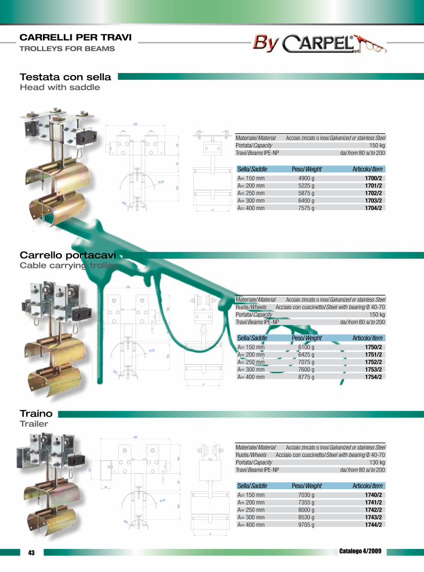
Testata con sellaHead with saddle
Carrello portacaviCable carrying trolley
9010
0
320
R100
A
150
R50
330
150
90
R100
A
150
R50
140
50
380
100
90
R100
A
150
R50
TrainoTrailer
Materiale/Material Acciaio zincato o inox/Galvanized or stainless SteelPortata/Capacity 150 kgTravi/Beams IPE-NP da/from 80 a/to 200
Materiale/Material Acciaio zincato o inox/Galvanized or stainless SteelRuote/Wheels Acciaio con cuscinetto/Steel with bearing Ø 40-70Portata/Capacity 150 kgTravi/Beams IPE-NP da/from 80 a/to 200
Materiale/Material Acciaio zincato o inox/Galvanized or stainless SteelRuote/Wheels Acciaio con cuscinetto/Steel with bearing Ø 40-70Portata/Capacity 130 kgTravi/Beams IPE-NP da/from 80 a/to 200
Sella/Saddle Peso/Weight Articolo/Item A= 150 mm 4900 g 1700/2A= 200 mm 5225 g 1701/2A= 250 mm 5875 g 1702/2A= 300 mm 6400 g 1703/2A= 400 mm 7575 g 1704/2
Sella/Saddle Peso/Weight Articolo/Item A= 150 mm 6100 g 1750/2A= 200 mm 6425 g 1751/2A= 250 mm 7075 g 1752/2A= 300 mm 7600 g 1753/2A= 400 mm 8775 g 1754/2
Sella/Saddle Peso/Weight Articolo/Item A= 150 mm 7030 g 1740/2A= 200 mm 7355 g 1741/2A= 250 mm 8000 g 1742/2A= 300 mm 8530 g 1743/2A= 400 mm 9705 g 1744/2
Catalogo 4/2009

44
CARRELLI PER TRAVI TROLLEYS FOR BEAMS
Connettore per cavo piatto - presa tipo CARPELConnector for flat cable - socket type CARPEL
Connettore per cavo piatto - presa tipo STANDARDConnector for flat cable - socket type STANDARD
Connettore per cavo tondo - presa tipo STANDARDConnector for round cable - socket type STANDARD
310
340
335
310
330
340
340
310
330
Articolo/Item 5060 5061 5062 10 Poli/Pole 16 Poli/Pole 24 Poli/Pole
Articolo/Item 3039 3040 3041 3042 10 Poli/Pole 16 Poli/Pole 24 Poli/Pole 32 Poli/Pole
Articolo/Item 4049 4050 4051 4052 10 Poli/Pole 16 Poli/Pole 24 Poli/Pole 32 Poli/Pole
Materiale/Material Acciaio zincato o inox/Galvanized or stainless Steel Presa in nylon/Nylon socketRuote/Wheels Acciaio con cuscinetto/Steel with bearing Ø 40Portata/Capacity 60 kgTravi/Beams IPE-NP da/from 80 a/to 140Peso/Weight 4310 kg
Materiale/Material Acciaio zincato o inox/Galvanized or stainless Steel Presa in alluminio/Alluminium socketRuote/Wheels Acciaio con cuscinetto/Steel with bearing Ø 40Portata/Capacity 60 kgTravi/Beams IPE-NP da/from 80 a/to 140Peso/Weight 4295 kg
Materiale/Material Acciaio zincato o inox/Galvanized or stainless Steel Presa in alluminio/Alluminium socket Ruote/Wheels Acciaio con cuscinetto/Steel with bearing Ø 40Portata/Capacity 60 kgTravi/Beams IPE-NP da/from 80 a/to 140Peso/Weight 4070 kg
Catalogo 4/2009

45
CARRELLI PER TRAVI TROLLEYS FOR BEAMS
ISTRUZIONI DI MONTAGGIO - linea con traino -ASSEMBLY INSTRUCTIONS - line with trailer -
1- Inserire la prima testata (senza sella) dalla parte opposta alla scatola di alimentazione, verificando che il tampone in PVC sia rivolto verso l’interno della linea. 2- Fissare la testata alla trave serrando le 4 viti delle staffe a “ L “. 3- Inserire il traino sulla trave dall’estremità senza testata. NOTA: nel caso della serie 7 , il traino non è simmetrico ed è quindi necessario verificare che il tampone in PVC sia rivolto verso l’interno della linea. 4- Inserire uno dopo l’altro tutti i carrelli sulla trave. 5- Inserire la seconda testata e fissarla, per mezzo delle 4 viti delle staffe a “ L “, all’estremità libera della trave verificando che il tampone in PVC sia rivolto verso l’interno della linea. 6- Inserire il cavo di alimentazione tra sella e controsella, partendo dalla testata dalla parte della scatola di alimentazione, arrivando fino al traino, passando per tutti i carrelli. 7- Lasciare alle due estremità della linea ( prima della testata e dopo il traino) sufficiente cavo per raggiungere la scatola di alimentazione e l’utilizzatore. Tra carrello e carrello lasciare il cavo necessario per ottenere l’ansa desiderata. 8- Fissare il cavo a tutti gli elementi della linea, serrando le viti delle relative selle.
1- Insert the first head (without saddle) from the supply box opposite side, paying attention so as the PVC plug is pointing towards the line inside. 2- Tighten the 4 screws of the “L” shaped stirrups to fix the head to the beam. 3- Insert the trailer into the beam from the headless end. REMARK: as to series 7, the trailer is not symmetrical and it is therefore necessary to make sure the PVC plug is pointing towards the line inside. 4- Insert ali the trolleys into the beam, one after the other. 5- Insert the second head and tighten the 4 screws of the “L” shaped stirrups to fix it to the beam free end, making sure the PVC plug is pointing towards the line inside. 6- Run the feeding cable between the saddle and the countersaddle, starting from the head at the supply box side, passing through ali the trolleys and ending at the trailer. 7- Make sure to leave enough cable length at the two line ends (before the head and after the trailer) to reach the supply box and the user. Leave enough cable length between each trolley to get the required loop. 8- Tighten the relevant saddle screws to fix the cable to all the line elements.
Misure normalizzate delle travi IPE - NPNormalised measures of IPE - NP beams
Al momento dell’ordine specificare la misura della trave lungo la quale devono scorrere i carrelli: Se si tratta di una trave normalizzata comunicare tipo e la dimen-sione; se invece la trave non è normalizzata o non rientra in quelle elencate di seguito, è necessario comunicare la larghezza dell’ala e il suo spessore.When placing your order, specify the measure of the beam where the trolleys will slide. For standardized beams, please advise the type and the dimension. For non-standardized beams or for beams not being included in the tables here below, it is important to advise the flange width and thickness.
h
b
e
a
b
ha
e
Travi/Beams IPEh (mm) b(mm) a (mm) e (mm)80 46 3,8 5,2100 55 4,1 5,7120 64 4,4 6,3140 73 4,7 6,9160 82 5,0 7,4180 91 5,3 8,0200 100 5,6 8,5220 110 5,9 9,2240 120 6,2 9,8270 135 6,6 10,2300 150 7,1 10,7
Travi/Beams NPh (mm) b(mm) a (mm) e (mm)80 42 3,9 5,8100 50 4,5 6,6120 58 5,1 7,5140 66 5,7 8,4160 74 6,3 9,3180 82 6,9 10,2200 90 7,5 11,0220 98 8,1 11,9240 106 8,7 12,8260 113 9,4 13,8300 119 10,1 14,8
Catalogo 4/2009

46

47
CARRELLI PER FUNE CARRELLI REGOLABILI E ACCESSORI TROLLEYS FOR ROPES, ADJUSTABLE TROLLEYS AND ACCESSORIES
Ci riserviamo la facoltà di apportare, senza alcun preavviso, modifiche costruttive al fine
di migliorare le qualità tecniche, funzionali ed estetiche del prodotto.
We reserve the right to make modifications in order to improve the technical, functional
and aesthetical qualities of our products without any prior notice.
Catalogo 5/2009

48
CARRELLI PER FUNE CARRELLI REGOLABILI E ACCESSORI TROLLEYS FOR ROPES, ADJUSTABLE TROLLEYS AND ACCESSORIES
Carrello per fune - a 1 ruota nylonTrolley for ropes - with 1 nylon wheel
Carrello per fune - a 2 ruote nylonTrolley for ropes - with 2 nylon wheels
Carrello per funeTrolley for ropes
Carrello per fune - a 2 ruote cuscinettoTrolley for ropes - with 2 wheels with bearing
58
max
. 30m
m
75
65
Fune Ø 8 - 12
Fune Ø 8 - 12
75
max
. 30m
m
103
65
42
3652
20
26
Cavo diam. da 8 a 10Cavo diam. da 10 a 12
Fune Ø8 - 12
58m
ax. 3
0mm
120
65
Articolo/Item 1304Codice/Code CRFU 65N1
Materiale/Material Corpo in nylon/Nylon body Minuteria in acciaio zincato/Small parts in galvanized steelRuote/Wheels Ø 45 mm in nylonPortata/Capacity 10 kg Peso/Weight 180 g
Articolo/Item 1324Codice/Code CRFU 65N2
Materiale/Material Corpo in nylon/Nylon body Minuteria in acciaio zincato/Small parts in galvanized steelRuote/Wheels Ø 45 mm in nylonPortata/Capacity 15 kg Peso/Weight 220 g
Materiale/Material Corpo in nylon/Nylon body Minuteria in acciaio zincato/Small parts in galvanized steelRuote/Wheels Ø 45 mm in nylonPortata/Capacity 10 kg Peso/Weight 15 g
Articolo/Item 1344Codice/Code CFA 65NC2
Materiale/Material Acciaio zincato/Galvanized steelRuote/Wheels Ø 45 mm in nylonPortata/Capacity 20 kg Peso/Weight 570 g
Catalogo 5/2009
Articolo/Item 1314Codice/Code CRFU T20N1

49
CARRELLI PER FUNE CARRELLI REGOLABILI E ACCESSORI TROLLEYS FOR ROPES, ADJUSTABLE TROLLEYS AND ACCESSORIES
Testata regolabileAdjustable head
Carrello regolabile a 2 ruoteAdjustable trolley with 2 wheels
Carrello regolabile a 4 ruoteAdjustable trolley with 4 wheels
Carrello regolabileAdjustable trolley
Travi da 60 a 300 mm
65mm
max
. 30m
m
( su richiesta disponibili fino ad ala 400mm )
35 mm
Travi da 60 a 200 mm
max
. 30m
m
64
92
( su richiesta disponibili fino ad ala 400mm )
Travi da 60 - 200 mm
max
. 30m
m
35 mm
( su richiesta disponibili fino ad ala 400mm )118
92
ALA: min.90mm - max.300mm
65
350
140
105
Articolo/Item 021Codice/Code TES REG 65
Materiale/Material Acciaio zincato/Galvanized steelPortata/Capacity 20 kg Peso/Weight 560 g
Articolo/Item 031 041Codice/Code CRES 65 N2 CRES 65 C2
Materiale/Material Corpo in nylon/Nylon body Minuteria in acciaio zincato/Small parts in galvanized steel Ruote nylon Ruote acciaio con cuscinetto Nylon wheels Steel wheels with bearingPortata/Capacity 5 kg 10 kgPeso/Weight 240 g 580 g
Articolo/Item 071Codice/Code CRES 65 N4
Materiale/Material Corpo in nylon/Nylon body Minuteria in acciaio zincato/Small parts in galvanized steel Ruote nylon/Nylon wheels Portata/Capacity 10 kg Peso/Weight 300 g
Articolo/Item 081Codice/Code CRES 65 C4
Materiale/Materiale Acciaio zincato/Galvanized steel Ruote acciaio con cuscinetto/Steel wheels with bearingPortata/Capacity 15 kgPeso/Weight 980 g
Catalogo 5/2009

50
CARRELLI PER FUNE CARRELLI REGOLABILI E ACCESSORI TROLLEYS FOR ROPES, ADJUSTABLE TROLLEYS AND ACCESSORIES
RespingentiBumpers
Tampone rettangolareRectangular plug
Tampone rettangolare raggiatoRectangular plug with radius
Codice/Code Articolo/Item A B C DRESPx4 x4 40 40 M8 25RESPx6 x6 60 50 M10 25RESPx8 x8 80 60 M12 25RESPx10 x10 100 80 M12 25RESPx12 x12 120 100 M14 30RESPx15 x15 150 120 M14 30
Articolo/Item 3401
Articolo/Item 3402
Materiale/Material PVC speciale/Special PVCPeso/Weight 105 g
Materiale/Material PVC speciale/Special PVCPeso/Weight 125 g
A
B
D
C
2317
9050
30
Ø10
432114
Ø18
98
Ø12
40
68
Catalogo 5/2009

51
CARRELLI PER FUNE CARRELLI REGOLABILI E ACCESSORI TROLLEYS FOR ROPES, ADJUSTABLE TROLLEYS AND ACCESSORIES
Pressacavo 55x18 per cavo piattoCable gland 55x18 for flat cable
Pressacavo 80x25 per cavo piattoCable gland 80x25 for flat cable
Pressacavo 55x18 con raccordo per attacco PG21Cable gland 55x18 with union for PG21 connection
Articolo/Item 3450 3451
Articolo/Item 3452
Articolo/Item 3453
Materiale/Material Nylon Alluminio/AluminiumPeso/Weight 105 g 160 g
Materiale/Material Alluminio/AluminiumPeso/Weight 340 g
Materiale/Material NylonPeso/Weight 120 g
80
120
25
Ø8
307
50
7
55
18
85
Ø6,4
6
6
25
37
3749
8555
PG21
18
10
Catalogo 5/2009

52
Anticollisione con staffeAnticollision device with stirrups
Anticollisione con ruote guida scorrimentoAnticollision device with sliding guide wheels
Staffe per anticollisioneStirrups for anticollision device
Codice/Code A B C Corsa/Stroke Articolo/ItemANTI 500 970 400 500 3500ANTI 800 1570 600 800 3501ANTI 1200 2470 1200 1200 3502ANTI 1350 2470 1050 1350 3503ANTI 1250 2470 1200 1250 3504
Codice/Code A B C Corsa/Stroke Articolo/ItemANTI 1600 3150 1200 1600 3505ANTI 2000 4150 1850 2000 3506ANTI 2500 4650 1850 2500 3507
Materiale/Material Acciaio zincato/Galvanized Steel
C
A
B
A
B C
CARRELLI PER FUNE CARRELLI REGOLABILI E ACCESSORI TROLLEYS FOR ROPES, ADJUSTABLE TROLLEYS AND ACCESSORIES
Articolo/Item 3509
100
2829
Catalogo 5/2009

53
CARRELLI PER FUNE CARRELLI REGOLABILI E ACCESSORI TROLLEYS FOR ROPES, ADJUSTABLE TROLLEYS AND ACCESSORIES
Ruote nylon con cuscinetto per travi Nylon wheels with bearing for beams
Ruote nylon per travi Nylon wheels for beams
Ruote acciaio per traviSteel wheels for beams
Ø29
Ø68
Ø70
8 1523
3
5
8
Ø32
Ø12
10
Cuscinetto 6201ZZ
A
A
SEZ. A-A
Ø88
Materiale/Material Acciaio zincato/Galvanized Steel
Ruote acciaio per traviSteel wheels for beams
Ø42Ø40
593226
19,5
11
35
11,5
A
ASEZ. A-A
Materiale/Material Acciaio zincato/Galvanized Steel
Articolo/Item 3702
SEZ. A-A
Ø42
Ø40
20
3
4.57.5
Ø32
Ø62
Ø27
A
A
Materiale/Material Nylon
Articolo/Item 3701
SEZ. A-A4.5
3
22
20
Ø40
Ø42
Ø33
Ø22
Ø16
.4
Ø12
10
8
A
AØ62
Materiale/Material Nylon
Articolo/Item 3700
Articolo/Item 3703
Catalogo 5/2009

54
CARRELLI PER FUNE CARRELLI REGOLABILI E ACCESSORI TROLLEYS FOR ROPES, ADJUSTABLE TROLLEYS AND ACCESSORIES
MensolaBracket
Staffe per bloccaggio su traveStirrups for beam clamping
Staffe curveBent stirrups
L
A
25
30
4
25
Vite/Screw M8x30
4
8
52
60 10
R22
Vite/Screw M8x50 Flang.
Dado Quadro M8 25
30
Articolo/Item 350 450 550 650 800Codice/Code MEN 1-350 MEN 1-450 MEN 1-550 MEN 1-650 MEN 1-800
Articolo/Item 1000 1001 1002 1003Codice/Code STA 1 L10 STA 1 L15 STA 1 L20 STA 1 L25
Materiale/Material Acciaio zincato/Galvanized Steel L=350mm L=450mm L=550mm L=650mm L=800mmPeso/Weight 721 g 840 g 959 g 1078 g 1257 gPortata/Capacity 35 kg 30 kg 25 kg 20 kg 15 kg
Materiale/Material Acciaio zincato/Galvanized Steel A=10mm A=15mm A=20mm A=25mmPeso/Weight 70 g 75 g 80 g 85 gPortata/Capacity 50 kg
Catalogo 5/2009
Materiale/Material Acciaio zincato/Galvanized SteelPeso/Weight 180 gPortata/Capacity 50 kg
Articolo/Item 3602Codice/Code STAFFECURVE

55
CARRELLI PER FUNE CARRELLI REGOLABILI E ACCESSORI TROLLEYS FOR ROPES, ADJUSTABLE TROLLEYS AND ACCESSORIES
C-Rail speciale 35x50Special C-Rail 35x50
Giunto bloccaggio tubo 40x40Blocking tube joint 40x40
Giunto bloccaggio tubo 50x50Blocking tube joint 50x50
35
50
12
2
39
104
39
41
N° 4 viti M8x30 FL.
41 104
104 51
49
104
N° 4 viti/screw M8x30
51
49
Materiale/Material Acciaio zincato/Galvanized SteelPeso/Weight 2,3 kg/m
Materiale/Material Acciaio zincato/Galvanized SteelPeso/Weight 890 g
Materiale/Material Acciaio zincato/Galvanized SteelPeso/Weight 980 g
Articolo/Item CRAIL
Articolo/Item 4101
Articolo/Item 4102
Catalogo 5/2009

56
CARRELLI PER FUNE CARRELLI REGOLABILI E ACCESSORI TROLLEYS FOR ROPES, ADJUSTABLE TROLLEYS AND ACCESSORIES
Custodia connettore con inserto a spina - tipo CARPELConnector case with plug insertion - type CARPEL
Custodia connettore con inserto a spina - tipo STANDARDConnector case with plug insertion - type STANDARD
74
Ø46
Ø36
10
22
12
Articolo/Item 3300 3302 16 Poli/Pole 24 Poli/Pole
Ferma anseLoop fastener
Materiale/Material Acciaio zincato/Galvanized SteelLunghezza utile interna Internal working lenght 150 mm 200 mm 250 mm 300 mm 400 mm
Articolo/Item 3800 3801 3802 3803 3804
Materiale/Material Nylon
Articolo/Item 3454
Materiale/Material NylonPeso/Weight 25 g
Articolo/Item 3301 3303 16 Poli/Pole 24 Poli/Pole
Materiale/Material Alluminio/Alluminium
Fungo portacavoCable carrying head
Catalogo 5/2009

57
CARRELLI PER FUNE CARRELLI REGOLABILI E ACCESSORI TROLLEYS FOR ROPES, ADJUSTABLE TROLLEYS AND ACCESSORIES
Catena GenoveseChain genoa style
Dadi quadriSquare nuts
MoschettoniSpring-clips
Stecche per carrello portaconnettoreSlats for connector carrying trolley
Carrello portaconnettoreConnector carrying trolley
Materiale/Material Acciaio zincato/Galvanized Steel
M4 M5 M6 M8 Articolo/Item 3603 3604 3600 3601
Articolo/Item 3306 3307
Articolo/Item 3304 3305
Materiale/Material Acciaio zincato/Galvanized Steel Inox
Materiale/Material Acciaio zincato/Galvanized Steel Inox
Materiale/Material Corpo alluminio/Body allminium
Catalogo 5/2009
Minuteria in acciaio zincato/Small parts in galvanized steel Tipo/Type Tipo/Type EUROPEO 2000Ruote cusc./Wheels Bearing Ø 25 mm Ø 32 mm
Articolo/Item 3101 3201
Materiale/Material Acciaio zincato/Galvanized Steel Tipo/Type Tipo/Type EUROPEO 2000Ruote cusc./Wheels Bearing Ø 25 mm Ø 32 mm
Articolo/Item 3102 3202

58
CARRELLI PER FUNE CARRELLI REGOLABILI E ACCESSORI TROLLEYS FOR ROPES, ADJUSTABLE TROLLEYS AND ACCESSORIES
Respingenti ferro tipo -A- corsa singolaSteel bumpers type -A- single stroke
E
F
A
D
CB
1
1,523456810203040506080100
150
200
1015
2030
4050
7010
015
020
0
EC = Kgm
( per un respingente ) Peso Totale della Gru in Tonn. = peso ponte : 2 + peso del carrello
Velo
cità
in m
/ m
in
EC 7 = A 06 TEC 15 = A 1 T
EC 33 = A 2 TEC 60 = A 3 T
EC 120 = A 5 TEC 200 = A 7 TEC 300 = A 10 TEC 500 = A 15 TEC 700 = A 20 T
EC 1200 = A 30 TEC 1700 = A 40 T
EC 2300 = A 50 T
EC 3 = A 03 T
Catalogo 5/2009
TIPO/TYPE Forza ammortizzante Corsa/Stroke DIMENSIONI/DIMENSIONS Cushioning force [kg] [mm] A B C D E F1.T 1000 40 120 158 6 11 130 1002.T 2000 50 145 185 6 13 150 1183.T 3000 60 175 230 7 15 170 1345.T 5000 70 190 260 7 17 185 1507.T 7000 75 200 290 8 19 200 16210.T 10000 85 225 310 8 21 215 17215.T 15000 95 250 365 10 23 260 21220.T 20000 100 290 420 10 25 300 24030.T 30000 110 305 465 12 25 330 26340.T 40000 120 320 512 14 28 330 26350.T 50000 130 350 545 16 28 350 278

59
Respingenti ferro tipo -B- corsa doppiaSteel bumpers type -B- double stroke
E
F
A
D
CB
1
1,523456810203040506080100
150
200
1015
2030
4050
7010
015
020
0EC = Kgm
( per un respingente ) Peso Totale della Gru in Tonn. = peso ponte : 2 + peso del carrello
Velo
cità
in m
/ m
in
EC 6 = B 03 T
EC 15 = B 06 T
EC 30 = B 1 T
EC 80 = B 2 TEC 150 = B 3 T
EC 270 = B 5 TEC 400 = B 7 TEC 650 = B 10 TEC 1100 = B 15 TEC 1600 = B 20 T
EC 2600 = B 30 TEC 3400 = B 40 T
EC 4600 = B 50 T
CARRELLI PER FUNE CARRELLI REGOLABILI E ACCESSORI TROLLEYS FOR ROPES, ADJUSTABLE TROLLEYS AND ACCESSORIES
Catalogo 5/2009
TIPO/TYPE Forza ammortizzante Corsa/Stroke DIMENSIONI/DIMENSIONS Cushioning force [kg] [mm] A B C D E F1.T 1000 80 120 263 6 11 130 1002.T 2000 100 145 335 6 13 150 1183.T 3000 120 175 390 7 15 170 1345.T 5000 140 190 452 7 17 185 1507.T 7000 150 200 502 8 19 200 16210.T 10000 170 225 564 8 21 215 17215.T 15000 190 250 627 10 23 260 21220.T 20000 200 290 672 10 25 300 24030.T 30000 220 305 775 12 25 330 26340.T 40000 220 320 838 14 28 330 26350.T 50000 230 350 924 16 28 350 278

60

61
LINEA TROLLEY ELITE TROLLEY ELITE LINE
La linea TROLLEY ELITE è un sistema particolarmente indicato per la
distribuzione dell’energia elettrica per macchine quali gru, carriponti
e macchine mobili in generale, installate all’interno o non esposte alle
intemperie (pioggia, spruzzi d’acqua, .... , etc.).
La linea TROLLEY ELITE è un sistema pratico, facile da installare, efficien-
te, in quanto richiede una manutenzione minima, ma soprattutto sicuro.
Infatti sul profilo in PVC del TROLLEY ELlTE, troverete apposta la mar-
catura “CE” a garanzia che il prodotto è costruito conformemente ai
Requisiti di Sicurezza dettati dalle Direttive:
- Direttiva CEE 73/23 e CEE 93/68 (Bassa Tensione)
- Direttiva CEE 89/336 e CEE 93/68 (EMC - compatibilità elettromagne-
tica) le cui prove/verifiche di sicurezza sono state eseguite in accordo
alle Norme CEI EN 60439-1 e CEI EN 60439-2.
A tal proposito, nelle pagine conclusive di questo catalogo, troverete
tutte le informazioni necessarie per un corretto dimensionamento, in-
stallazione e utilizzo del prodotto stesso.
The TROLLEY ELITE line is a system particularly indicated to supply po-
wer for machine as: cranes, bridge cranes and any other mobile machi-
ne. For internal installation or not expose to rain or sprinkle or water.
The TROLLEY ELITE line is a pratical system, easy to install, efficient,
because need just a little maintenance, but it is, above all, safe.
In fact, the TROLLEY ELITE has been labelled with the “CE” mark to
guarantee that the product meets:
- CEE 73/23 end CEE 93/68 (Low voltage)
- CEE 89/336 end CEE 93/68 (electromagnetic compatibility)
Test/inspections have been carried out in accordance with the effective
harminized/european standards CEI EN 60439-1 e CEI EN 60439-2. To
this end, the latest pages of this catalogue show all the information
required for a correct sizing, installation and use of the product allowing
to safely as state in the above said Standard.
Ci riserviamo la facoltà di apportare, senza alcun preavviso, modifiche costruttive al fine
di migliorare le qualità tecniche, funzionali ed estetiche del prodotto.
We reserve the right to make modifications in order to improve the technical, functional
and aesthetical qualities of our products without any prior notice.
Catalogo 6/2009
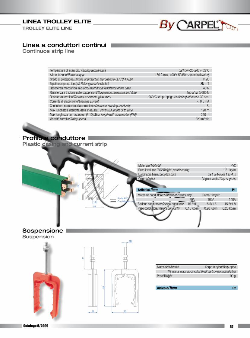
62
LINEA TROLLEY ELITE TROLLEY ELITE LINE
Profilo a conduttorePlastic casing and current strip
SospensioneSuspension
Articolo/Item P2
Materiale/Material Corpo in nylon/Body nylon Minuteria in acciaio zincato/Small parts in galvanized steelPeso/Weight 90 g
M8
85
116
28 85
12
56
75
Profilo PVCConduttore in rame
Articolo/Item P1Materiale conduttore/Material of current strip Rame/Copper 70A 100A 140ASezione conduttore/Section conductor 15.5x1 15.5x1.5 15.5x1.8Peso conduttore/Weight conductor 0.15 Kg/m 0.20 Kg/m 0.25 Kg/m
Materiale/Material PVCPeso involucro PVC/Weight plastic casing 1.21 kg/mLunghezza barre/Length’s bars da 1 a 4/from 1 to 4 mColore/Colour Grigio o verde/Grey or green
Temperatura di esercizio/Working temperature da/from -20 a/to + 55°CAlimentazione/Power supply 150 A max, 400 V, 50/60 Hz (nominali/rated)Grado di protezione/Degree of protection (according ti CEI 70-1 I ED) IP 205 poli (compreso terra)/5 Poles (ground included) 3N + TResistenza meccanica involucro/Mechanical resistance of the case 40 NResistenza a trazione sulle sospensioni/Suspension resistance and drive fino a/up to 680 NResistenza termica/Thermal resistance (glow-wire) 960°C tempo spegn./switching off time < 30 sec.Corrente di dispersione/Leakage current < 0,5 mAConduttore resistente alla corrosione/Corrosion-proofing conductor SIMax lunghezza interrotta della linea/Max. continuos length of th eline 120 mMax lunghezza con accessori (P 10)/Max. length with accessories (P10) 250 mVelocità carrello/Trolley speed 220 m/min
Linea a conduttori continuiContinuos strip line
Catalogo 6/2009
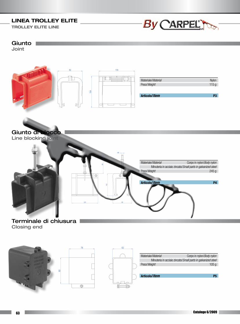
63
LINEA TROLLEY ELITE TROLLEY ELITE LINE
Giunto di bloccoLine blocking joint
Terminale di chiusuraClosing end
120 88
102
M8
85
6278
80
Articolo/Item P4
Articolo/Item P5
Materiale/Material Corpo in nylon/Body nylon Minuteria in acciaio zincato/Small parts in galvanized steelPeso/Weight 245 g
Materiale/Material Corpo in nylon/Body nylon Minuteria in acciaio zincato/Small parts in galvanized steelPeso/Weight 105 g
GiuntoJoint
Articolo/Item P3
Materiale/Material NylonPeso/Weight 115 g
82 118
104
Catalogo 6/2009

64
LINEA TROLLEY ELITE TROLLEY ELITE LINE
Scatola di alimentazione internaInternal feeding
CarrelloTrolley
Articolo/Item P8
Articolo/Item P7
Materiale/Material Corpo in nylon/Body nylon Minuteria in acciaio zincato/Small parts in galvanized steel Spazzole in metalgrafite/Slinding shoe: carbonPortata/Load 32 A 4 poli/poles 5 poli/poles Cavo/Cable Cavo/Cable Cavo/Cable Cavo/Cable 3m 5m 3m 5mPeso/Weight 1275 g 1740 g 1585 g 2050 g
Per esigenze di portata superiore ai 32 A è necessario collegare in parallelo due o più carrelli.For higher currents and duty cycles two or more trolley have to be connected in parallel.
Materiale/Material Corpo in nylon/Body nylon Minuteria in acciaio zincato/Small parts in galvanized steelPeso/Weight 360 g
188
111
54
35
PioloTooth
118 138
117
Scatola di alimentazione di testaHead feeding
140 125
125
Articolo/Item P6
Materiale/Material Corpo in nylon/Body nylon Minuteria in acciaio zincato/Small parts in galvanized steelPeso/Weight 415 g
Catalogo 6/2009

65
LINEA TROLLEY ELITE TROLLEY ELITE LINE
Braccio di traino doppioDouble towing arm
Supporto per bracci di trainoSupport for towing arms
Cerniera
Vite M8x90
320
1864
156
6418
240285
107
113
107
53
750
240
190
285
536
Braccio di traino singoloSingle towing arm
Articolo/Item P9/1
Materiale/Material Acciao zincato/Galvanized steelPeso/Weight 880 g10
6
52
240
64100
285
Cerniera
Vite M8x90
Articolo/Item P9/2
Articolo/Item P9/M
Materiale/Material Acciao zincato/Galvanized steelPeso/Weight 1800 g
Materiale/Material Acciao zincato/Galvanized steelPeso/Weight 1900 g
Catalogo 6/2009

66
LINEA TROLLEY ELITE TROLLEY ELITE LINE
GuarnizioneWascher
Blocco inserzione carrelloTrolley insertion
MensolaBracket
Articolo/Item P13
Materiale/Material Acciao zincato/Galvanized steelPeso/Weight 775 g
300
650
Articolo/Item P11
Articolo/Item P12
Materiale/Material PVC semirigido/Semi-stiff PVCPeso/Weight 65 g/m
Materiale/Material NylonPeso/Weight 595 g
Gancio
MollaCatena
Articolo/Item P10
Materiale/Material Acciao zincato/Galvanized steelPeso/Weight 715 g
Molla di dilatazioneExpansion spring
Catalogo 6/2009

67
LINEA TROLLEY ELITE TROLLEY ELITE LINE
Accessori per il montaggio del conduttoreParts for conductor assembly
Aspo svolgirameReel to unwind copper
Carrello tirarameConductor guiding trolley
Ruota inferiore - superiore Upper - Lower wheel
Molla per pattino di contattoSpring for sliding shoe
RicambiSpare parts
Bussola ottone ruoteBrass bush for wheels
Catalogo 6/2009

68
LINEA TROLLEY ELITE TROLLEY ELITE LINE
Esempi di linee di alimentazioneExample of feed line
Lin
ea
co
n a
lime
nta
zio
ne
di te
sta
He
ad
fe
ed
lin
e
Lin
ea
co
n a
lime
nta
zio
ne
inte
rna
Inne
r fe
ed
lin
e
Art.
P6
Art.
P1
Art.
P4
Art.
P3Ar
t. P2
Art.
P10
Art.
P5
Art.
P10
Art.
P3Ar
t. P2
Art.
P7
Art.
P7Ar
t. P4
Art.
P1Ar
t. P5
Art.
P10
Catalogo 6/2009
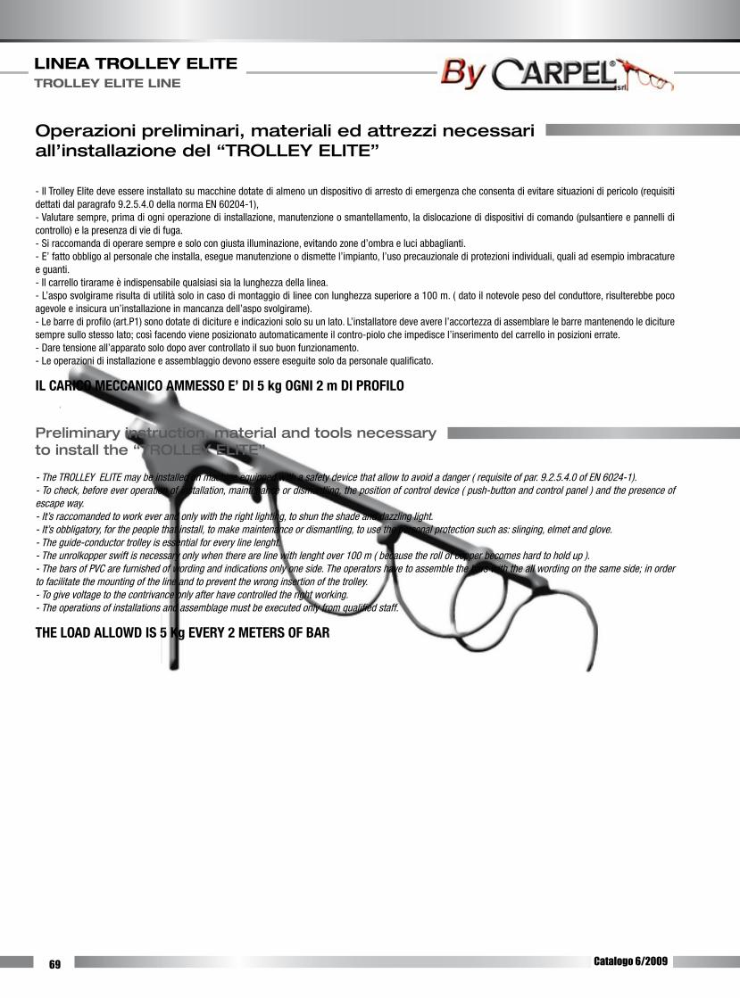
69
LINEA TROLLEY ELITE TROLLEY ELITE LINE
Operazioni preliminari, materiali ed attrezzi necessari all’installazione del “TROLLEY ELITE”
- Il Trolley Elite deve essere installato su macchine dotate di almeno un dispositivo di arresto di emergenza che consenta di evitare situazioni di pericolo (requisiti dettati dal paragrafo 9.2.5.4.0 della norma EN 60204-1), - Valutare sempre, prima di ogni operazione di installazione, manutenzione o smantellamento, la dislocazione di dispositivi di comando (pulsantiere e pannelli di controllo) e la presenza di vie di fuga. - Si raccomanda di operare sempre e solo con giusta illuminazione, evitando zone d’ombra e luci abbaglianti. - E’ fatto obbligo al personale che installa, esegue manutenzione o dismette l’impianto, l’uso precauzionale di protezioni individuali, quali ad esempio imbracature e guanti. - Il carrello tirarame è indispensabile qualsiasi sia la lunghezza della linea. - L’aspo svolgirame risulta di utilità solo in caso di montaggio di linee con lunghezza superiore a 100 m. ( dato il notevole peso del conduttore, risulterebbe poco agevole e insicura un’installazione in mancanza dell’aspo svolgirame). - Le barre di profilo (art.P1) sono dotate di diciture e indicazioni solo su un lato. L’installatore deve avere l’accortezza di assemblare le barre mantenendo le diciture sempre sullo stesso lato; così facendo viene posizionato automaticamente il contro-piolo che impedisce l’inserimento del carrello in posizioni errate. - Dare tensione all’apparato solo dopo aver controllato il suo buon funzionamento. - Le operazioni di installazione e assemblaggio devono essere eseguite solo da personale qualificato.
IL CARICO MECCANICO AMMESSO E’ DI 5 kg OGNI 2 m DI PROFILO
Preliminary instruction, material and tools necessary to install the “TROLLEY ELITE”
- The TROLLEY ELITE may be installed on machine equipped with a safety device that allow to avoid a danger ( requisite of par. 9.2.5.4.0 of EN 6024-1). - To check, before ever operation of installation, maintenance or dismantling, the position of control device ( push-button and control panel ) and the presence of escape way. - It’s raccomanded to work ever and only with the right lighting, to shun the shade and dazzling Iight. - It’s obbligatory, for the people that install, to make maintenance or dismantling, to use the personal protection such as: slinging, elmet and glove. - The guide-conductor trolley is essential for every line lenght. - The unrolkopper swift is necessary only when there are line with lenght over 100 m ( because the roll of copper becomes hard to hold up ). - The bars of PVC are furnished of wording and indications only one side. The operators have to assemble the bars with the all wording on the same side; in order to facilitate the mounting of the line and to prevent the wrong insertion of the trolley. - To give voltage to the contrivance only after have controlled the right working.- The operations of installations and assemblage must be executed only from qualified staff.
THE LOAD ALLOWD IS 5 Kg EVERY 2 METERS OF BAR
Catalogo 6/2009
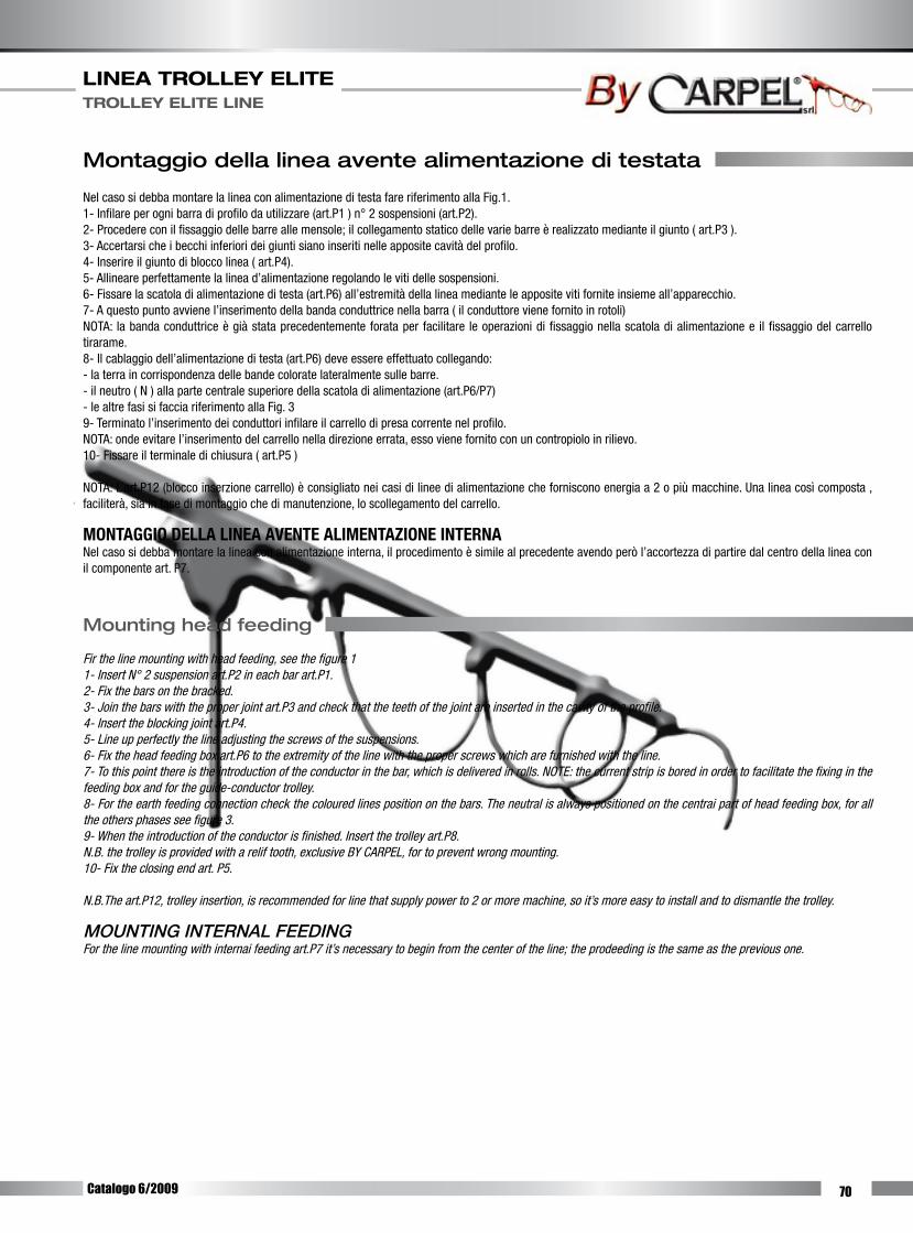
70
LINEA TROLLEY ELITE TROLLEY ELITE LINE
Montaggio della linea avente alimentazione di testata
Nel caso si debba montare la linea con alimentazione di testa fare riferimento alla Fig.1. 1- Infilare per ogni barra di profilo da utilizzare (art.P1 ) n° 2 sospensioni (art.P2). 2- Procedere con il fissaggio delle barre alle mensole; il collegamento statico delle varie barre è realizzato mediante il giunto ( art.P3 ). 3- Accertarsi che i becchi inferiori dei giunti siano inseriti nelle apposite cavità del profilo. 4- Inserire il giunto di blocco linea ( art.P4). 5- Allineare perfettamente la linea d’alimentazione regolando le viti delle sospensioni. 6- Fissare la scatola di alimentazione di testa (art.P6) all’estremità della linea mediante le apposite viti fornite insieme all’apparecchio. 7- A questo punto avviene l’inserimento della banda conduttrice nella barra ( il conduttore viene fornito in rotoli) NOTA: la banda conduttrice è già stata precedentemente forata per facilitare le operazioni di fissaggio nella scatola di alimentazione e il fissaggio del carrello tirarame. 8- Il cablaggio dell’alimentazione di testa (art.P6) deve essere effettuato collegando: - la terra in corrispondenza delle bande colorate lateralmente sulle barre. - il neutro ( N ) alla parte centrale superiore della scatola di alimentazione (art.P6/P7) - le altre fasi si faccia riferimento alla Fig. 3 9- Terminato l’inserimento dei conduttori infilare il carrello di presa corrente nel profilo. NOTA: onde evitare l’inserimento del carrello nella direzione errata, esso viene fornito con un contropiolo in rilievo. 10- Fissare il terminale di chiusura ( art.P5 )
NOTA: L’art.P12 (blocco inserzione carrello) è consigliato nei casi di linee di alimentazione che forniscono energia a 2 o più macchine. Una linea così composta , faciliterà, sia in fase di montaggio che di manutenzione, lo scollegamento del carrello.
MONTAGGIO DELLA LINEA AVENTE ALIMENTAZIONE INTERNA Nel caso si debba montare la linea con alimentazione interna, il procedimento è simile al precedente avendo però l’accortezza di partire dal centro della linea con il componente art. P7.
Mounting head feeding
Fir the line mounting with head feeding, see the figure 1 1- Insert N° 2 suspension art.P2 in each bar art.P1. 2- Fix the bars on the bracked. 3- Join the bars with the proper joint art.P3 and check that the teeth of the joint are inserted in the cavity of the profile. 4- Insert the blocking joint art.P4. 5- Line up perfectly the line adjusting the screws of the suspensions. 6- Fix the head feeding box art.P6 to the extremity of the line with the proper screws which are furnished with the line. 7- To this point there is the introduction of the conductor in the bar, which is delivered in rolls. NOTE: the current strip is bored in order to facilitate the fixing in the feeding box and for the guide-conductor trolley. 8- For the earth feeding connection check the coloured lines position on the bars. The neutral is always positioned on the centrai part of head feeding box, for all the others phases see figure 3. 9- When the introduction of the conductor is finished. Insert the trolley art.P8. N.B. the trolley is provided with a relif tooth, exclusive BY CARPEL, for to prevent wrong mounting. 10- Fix the closing end art. P5.
N.B.The art.P12, trolley insertion, is recommended for line that supply power to 2 or more machine, so it’s more easy to install and to dismantle the trolley.
MOUNTING INTERNAL FEEDING For the line mounting with internai feeding art.P7 it’s necessary to begin from the center of the line; the prodeeding is the same as the previous one.
Catalogo 6/2009

71
LINEA TROLLEY ELITE TROLLEY ELITE LINE
L’IDENTIFICAZIONE DELLE FASI DI CON-NESSIONE DEVE ESSERE EFFETTUATA OBBLIGATORIAMENTE DALL’INSTALLA-TORE DELLA LINEA, UTILIZZANDO LE APPOSITE ETICHETTE FORNITE.
Identification of logon phases must be obligatory done from the person who mount the line using the appropriate supplied labels.
La linea TROLLEY ELITE è stata progettata, costruita ed equipaggiata in modo tale da limitare le cause di intervento degli operatori. Il TROLLEY ELITE non richiede particolari e difficili operazioni di manutenzione; attenendosi scrupolosamente alle indicazioni di seguito elencate, si otterrà la massima funzionalità e la massima durata del prodotto.
- Dopo i primi tre mesi dalla messa in funzione della linea d’alimentazione verificare il perfetto allineamento delle sbarre, verificare inoltre che il TROLLEY ELITE sia parallelo alle rotaie dell’impianto ( gru, carroponte, etc .. ) - Ogni sei mesi controllare che i pattini di contatto abbiano una sporgenza dal lato esterno del carrello di almeno 5 mm, nel caso contrario si rende necessaria la sostituzione dei pattini e/o delle molle. - Ad ogni operazione di manutenzione verificare lo scorrimento del carrello nelle sedi, se queste ultime risultassero occluse da polvere o altro, rimuovere il materiale ostruente. - Accertarsi che la cerniera del traino sia oliata - Durante ogni operazione è vietato l’uso di mezzi impropri (colpi di martello, etc .. )
NOTA: per sfilare il carrello si può rimuovere il terminale di chusura, oppure se è stato montato l’apposito “blocco inserimento carrello”, è sufficiente smontare lo stesso (art. P12).
TUTTE LE OPERAZIONI DI MANUTENZIONI DEVONO VENIRE EFFETTUATE AD IMPIANTI FERMI E NON SOTTO TENSIONE.
The TROLLEY ELITE line is projected, built and fitted, to limit the intervention of the operators. The TROLLEY ELITE doesn’t need particular and difficult operation of maintenance. If you follow the indication you can obtain the best functionality and the best duration of the line.
- After three month, verify the perfect alignment of the line; verify that the TROLLEY ELITE is parallel to the rail of the machine (crane, etc.). - Every six month check that the sliding shoes sticks out about 5 mm, or else it’s necessary to replace the sliding shoes and the spring. - During every operation of maintenance, verify the sliding of the trolley in the bars; or else removethe dust and every thing that can block up the sliding of the trolley. - Verify that the hinge of the towing arm is olied. - During every operation is forbbiden to used improper means ( as hammer-stroke, etc.).
N.B. To dismantle the trolley is possible remove the closing end or, if the “trolley insertion” art. P.12 is mounted, is possible remove it.
EVERY OPERATION OF MAINTENANCE MUST BE EFFECTED WITH EVERY EQUIPMENT STOPPED AND WITHOUT TENSION .
Fig. 3: ESEMPIO DI CONNESSIONE DEI CONDUTTORI (Art. P6) Fig. 3: MODALlTY OF CONNECTION OF CONDUCTORS(Art.P6)
L3L2
L1
N
ContropioloContrast toot
Catalogo 6/2009

72
73
CAVI AUTOPORTANTI UTENZE MOBILI SELF-SUPPORTING CABLES FOR MOVING EQUIPMENT
Ci riserviamo la facoltà di apportare, senza alcun preavviso, modifiche costruttive al fine
di migliorare le qualità tecniche, funzionali ed estetiche del prodotto.
We reserve the right to make modifications in order to improve the technical, functional
and aesthetical qualities of our products without any prior notice.
Catalogo 7/2009

74
CAVI PIATTI PER UTENZE MOBILI FLAT CABLES FOR MOVING EQUIPMENT
N° conduttoriN° conductors
6 9 12 16 20 24
N° conduttori per gruppoN° conductors for group
2x3 3x3 3x4 4x4 5x4 6x4
Sezione mm2
Section mm2
0,75 1,5 2,5 4 6 10
Resistenza elettricaConductors resistance
26,00 13,30 7,98 4,95 3,30 1,91
Sezione mm2
Section mm2
16 25 35 50
Resistenza elettricaConductors resistance
1,21 0,78 0,55 0,38
Formazione e costruzione cavi/Formation
Denominazione/Description: HO7VVH6-FCostruzione/Construction H - Cavo armonizzato/Harmonized cable05 - Tensione nominale/Nominal tension 2 U
0 /U: 300/500 V
oppure/or07 - Tensione nominale/Nominal tension 3 U
0 /U: 450/750 V
V - Isolamento PVC tipo TI2/Insulation with TI2 PVCV - Guaina PVC tipo TM 2/Outler sheath with TM2 PVCH6 - Cavo piatto con più di 4 conduttori/Flatform cable with more than 4 conductF - Conduttore di tipo flessibile/Flexible conductors
F - Conduttore di tipo flessibile/Flexible conductorsR - Isolamento PVC tipo TI 1/Insulation with TI1 PVCD - Cavo piatto/Flatform cableR - Guaina PVC tipo TM 2/Outler sheath with TM2 PVCIdentificazione/IdentificationIdentificazione anime secondo tabella CEI-UNEL 00722: con numerazione progressiva, con o senza conduttore di protezione giallo verde. Guaina esterna di preferenza in colore blu. Su specifica richiesta del cliente e per quantitativi minimi di 3-4000 m, possibilità di fornitura in colore nero.Cores identification according to CEI-UNEL 00722 tables; usually with progressive num-bering, with or without green-yellow conductor: Blue outer sheath. On request and for minimun quantitative or 3-4000 m, possibility of supplying with black outer sheath.Norme di riferimento/StandardsCEI 20-27 sigle di designazioneTabella UNEL 35010 sigle di designazioneCEI 20-29/IEC 228 conduttori cavi isolati/conductors for insulated cablesCEI 20-20/IEC 227 cavi isolati per PVC/PVC insulated cableCEI 20-35/IEC 332.1 non propagazione della fiamma/Flame retardantCEI 20-25 cavi flessibili piatti sotto guaina di PVC, per ascensoriCENELEC HD 359 S2
Impiego/ApplicationCavi adatti per installazione su macchine mobili velocità di spostamento non superiore a 1.6 m/s, con temperatura ambiente non inferiore a 15°C e superiore a +80°C.Cable used in moving equipment with shifting rate of 1.6 m/s. To be used at temparature ranging from -15°C and +80°C.
Catalogo 7/2009
N° conduttor-conductors
x mm2
DimensioniSize
mm x mm
PesoWeight
g/mmm2
PortataCapacity max.amp.
4x1,5 5,4x15,6 160 6 20
8x1,5 5,4x29,1 310 12 20
12x1,5 5,4x42,6 470 18 20
16x1,5 5,4x56,1 630 24 20
18x1,5 11,2x46,1 700 27 20
20x1,5 11,4x47,1 780 30 20
24x1,5 11,8x46,5 950 36 20
4x2,5 6,0x19,0 220 10 27
8x2,5 8,2x24,3 440 20 27
12x2,5 6,0x52,6 650 30 27
16x2,5 12,9x40,2 890 40 27
18x2,5 11,6x51,6 1010 45 27
4x4 6,9x21,0 330 16 36
4x6 7,7x24,2 450 24 48
4x10 10,1x30,2 720 40 63
4x16 11,0x35,4 1100 64 85
4x25 12,3x40,8 1550 100 112
4x35 15,4x49,9 2100 140 138
4x50 20,2x64,1 3150 200 168
Diametro esterno nominale - Tolleranza +/- 0,5 mmNominal outer diameter -Tolerance +/- 0,5 mm

75
CAVI AUTOPORTANTI UTENZE MOBILI SELF-SUPPORTING CABLES FOR MOVING EQUIPMENT
N° conduttoriN° conductors
x mm2
DimensioniSize
mm x mm
PesoWeight
g/mmm2
5X1 9,8x20,0 230 5
7x1 9,8x20,0 250 7
8x1,510x1
13,9x26,013,8x26,5
420350
1210
12x1,5 17,3x32,0 560 18
16x1,5 19,1x34,0 640 24
18x1,5 20,0x35,0 730 27
20x1,5 21,1x35,6 790 30
24x1,5 23,0x37,6 880 36
Diametro esterno nominale - Tolleranza +/- 0,5 mmNominal outer diameter -Tolerance +/- 0,5 mm
Costruzione/Construction FF - Conduttore extraflessibile rame rosso o stagnato/Extra-flexible conductors in plain or tinned annealed copperR - Isolamento PVC tipo TI2/Insulation with TI2 PVC07 - Cordatura a corone concentriche separate tra loro da nastro tessile/Lay-up in con-centric layers separated by a textile tapeY - Funi in acciaio zincato/ Galvanized steel ropesR - Guaina PVC tipo TM 2/Outer sheath inTM2 PVCIdentificazione/IdentificationIdentificazione anime secondo tabella CEI-UNEL 00722: con numerazione progressiva, con o senza conduttore di protezione giallo verde. Guaina esterna di preferenza in colore blu. Su specifica richiesta del cliente e per quantitativi minimi di 3-4000 m, possibilità di fornitura in colore nero.Cores identification according to CEI-UNEL 00722 tables; usually with progressive num-bering, with or without green-yellow conductor: Blue outer sheath. On request and for minimun quantitative or 3-4000 m, possibility of supplying with black outer sheath.Norme di riferimento/StandardsTabella UNEL 35010 sigle di designazioneCCEI 20-29/IEC 228 conduttori cavi isolati/conductors for insulated cablesCEI 20-20/IEC 227 cavi isolati per PVC/PVC insulated cableCEI 20-35/IEC 332.1 non propagazione della fiamma/Flame retardantImpiego/ApplicationIn questo cavo di comando gli sforzi di trazione vengono sostenuti da 2 funi laterali in-serite nella guaina esterna. Le funicelle hanno una resistenza alla trazone di 2100 N. Il cavo trova la sua applicazione in pulsantiere pensili, macchine per cantieri e sistemi di movimentazione e sollevamenti.Per migliorare la flessibilità il fascio interno dei conduttori è rivestito da un nastro tessile che miglioa le possibilità di movimento reciproco fra i conduttori e la guaina.The tensile stress in this control cable is supported by 2 side ropes inserted in th eouter sheath. Th esteel ropes have a tensile strengh of 2100 N: The cable is used in pendant push-button panels, yard machines, handling and lifting systems.In order to improve flexibility, the inner conductor bundle is wrapped in a textile tape which improves the capability of reciprocal motion between conductors and outer sheath.
Formazione e costruzione cavi/Formation
Catalogo 7/2009


