Embed Size (px)
Citation preview
Ch.9 Tolerancing
Why tolerance is so important in manufacturing Types of tolerance presentation Important terms you want to be familiar with Fit types Basic hole vs. basic shaft system Concept of geometric dimensioning and
tolerancing
Objective: Learn how to present tolerance, types of tolerance presentation, fit types and terminology
Tolerancing – why is it needed?
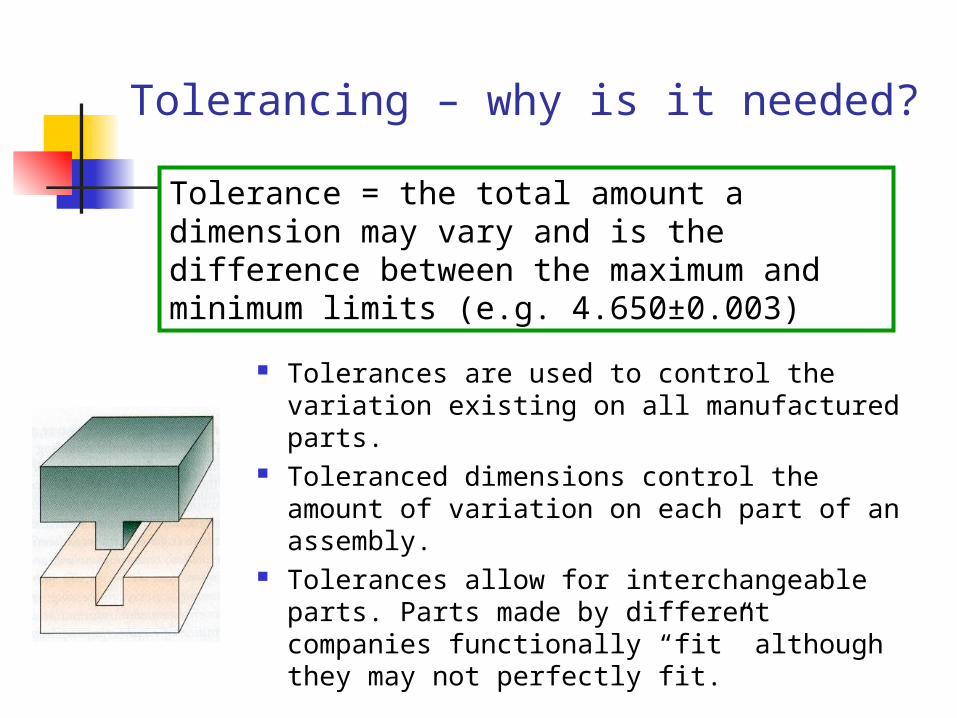
Tolerances are used to control the variation existing on all manufactured parts.
Toleranced dimensions control the amount of variation on each part of an assembly.
Tolerances allow for interchangeable parts. Parts made by different companies functionally “fit” although they may not perfectly fit.
Tolerance = the total amount a dimension may vary and is the difference between the maximum and minimum limits (e.g. 4.650±0.003)
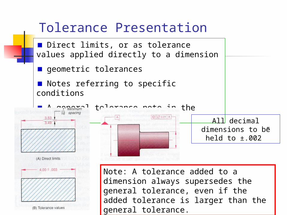
Tolerance Presentation Direct limits, or as tolerance values applied
directly to a dimension
geometric tolerances
Notes referring to specific conditions
A general tolerance note in the title block
All decimal dimensions to be held to ±.002”
Note: A tolerance added to a dimension always supersedes the general tolerance, even if the added tolerance is larger than the general tolerance.
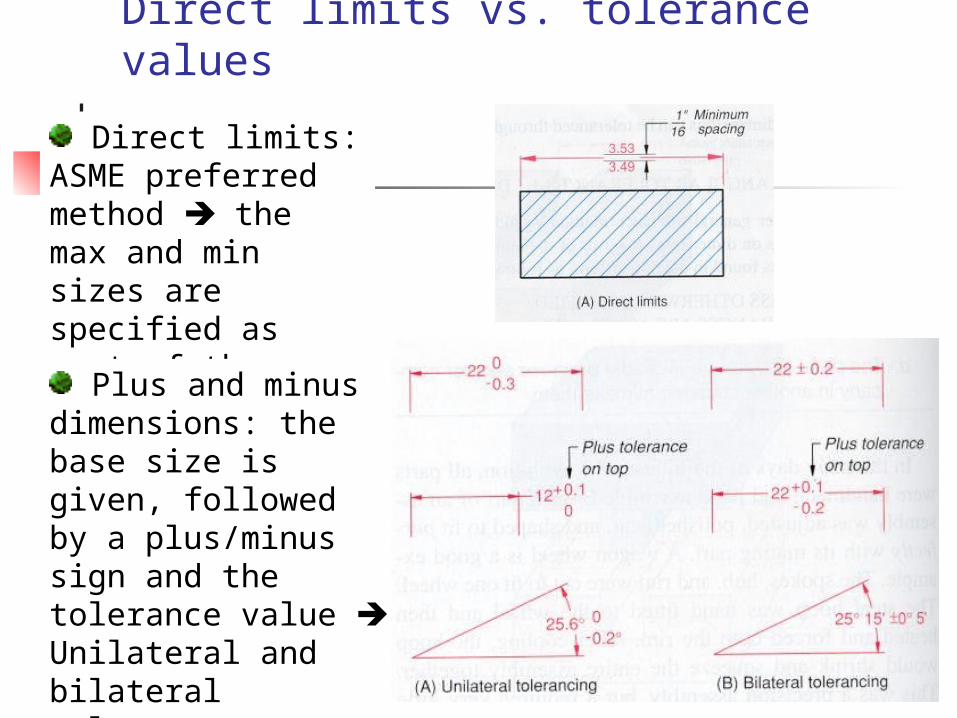
Direct limits vs. tolerance values
Direct limits: ASME preferred method the max and min sizes are specified as part of the dimension.
Plus and minus dimensions: the base size is given, followed by a plus/minus sign and the tolerance value Unilateral and bilateral tolerance.
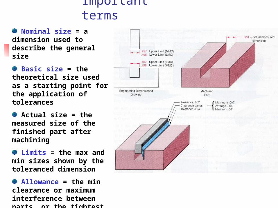
Important terms Nominal size = a
dimension used to describe the general size
Basic size = the theoretical size used as a starting point for the application of tolerances
Actual size = the measured size of the finished part after machining
Limits = the max and min sizes shown by the toleranced dimension
Allowance = the min clearance or maximum interference between parts, or the tightest fit between two mating parts
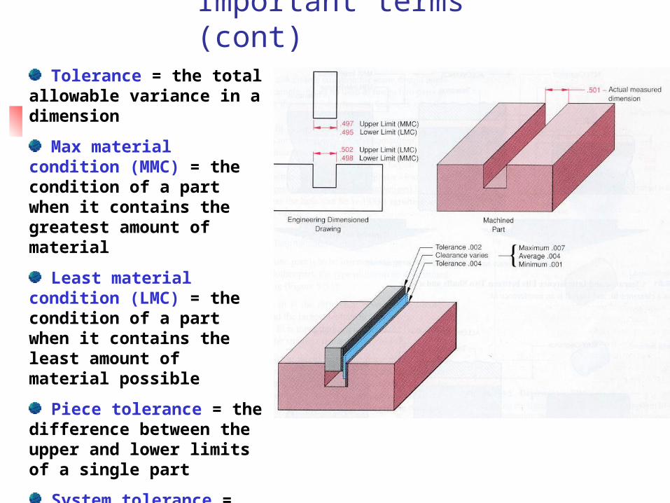
Important terms (cont)
Tolerance = the total allowable variance in a dimension
Max material condition (MMC) = the condition of a part when it contains the greatest amount of material
Least material condition (LMC) = the condition of a part when it contains the least amount of material possible
Piece tolerance = the difference between the upper and lower limits of a single part
System tolerance = the sum of all the piece tolerances

Fit types
Type 1: Clearance fit = Occurs when two toleranced mating parts will always leave a space or clearance when assembled
Type 2: Interference fit = Occurs when two toleranced mating parts will always interfere when assembled
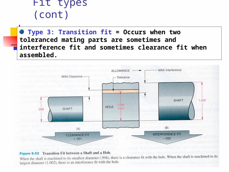
Fit types (cont)
Type 3: Transition fit = Occurs when two toleranced mating parts are sometimes and interference fit and sometimes clearance fit when assembled.
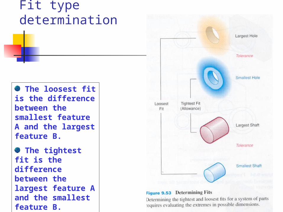
Fit type determination
The loosest fit is the difference between the smallest feature A and the largest feature B.
The tightest fit is the difference between the largest feature A and the smallest feature B.
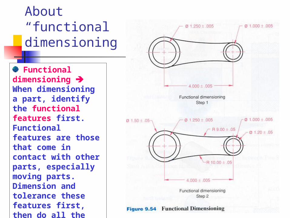
About “functional dimensioning”
Functional dimensioning When dimensioning a part, identify the functional features first. Functional features are those that come in contact with other parts, especially moving parts. Dimension and tolerance these features first, then do all the remaining features.
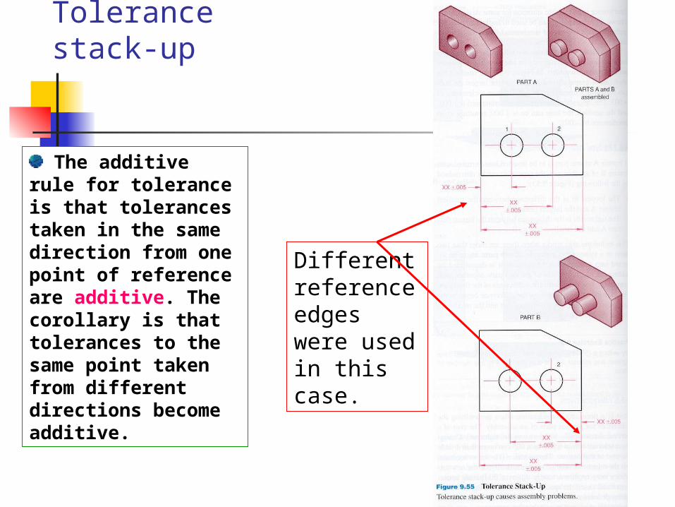
Tolerance stack-up
The additive rule for tolerance is that tolerances taken in the same direction from one point of reference are additive. The corollary is that tolerances to the same point taken from different directions become additive.
Different reference edges were used in this case.
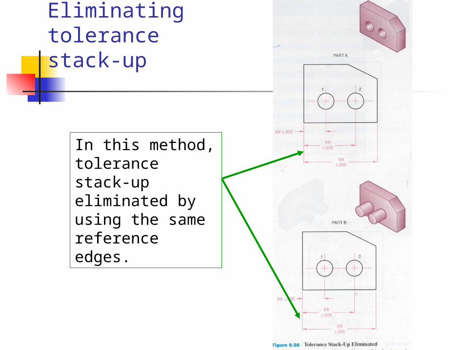
Eliminating tolerance stack-up
In this method, tolerance stack-up eliminated by using the same reference edges.
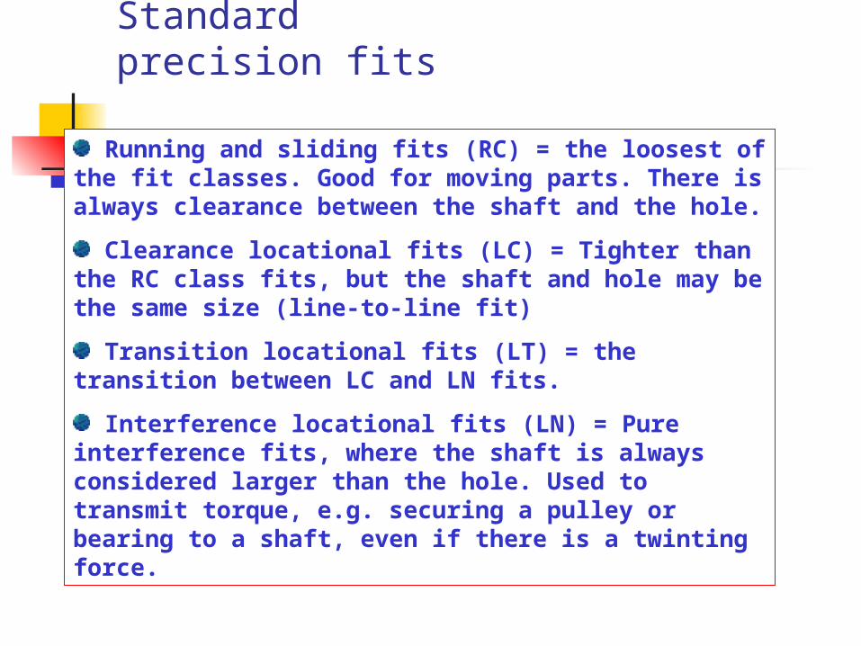
Standard precision fits
Running and sliding fits (RC) = the loosest of the fit classes. Good for moving parts. There is always clearance between the shaft and the hole.
Clearance locational fits (LC) = Tighter than the RC class fits, but the shaft and hole may be the same size (line-to-line fit)
Transition locational fits (LT) = the transition between LC and LN fits.
Interference locational fits (LN) = Pure interference fits, where the shaft is always considered larger than the hole. Used to transmit torque, e.g. securing a pulley or bearing to a shaft, even if there is a twinting force.
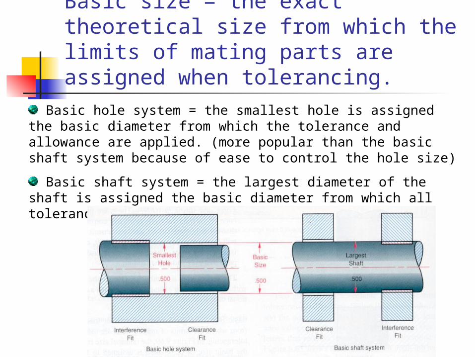
Basic size = the exact theoretical size from which the limits of mating parts are assigned when tolerancing.
Basic hole system = the smallest hole is assigned the basic diameter from which the tolerance and allowance are applied. (more popular than the basic shaft system because of ease to control the hole size)
Basic shaft system = the largest diameter of the shaft is assigned the basic diameter from which all tolerances are applied.
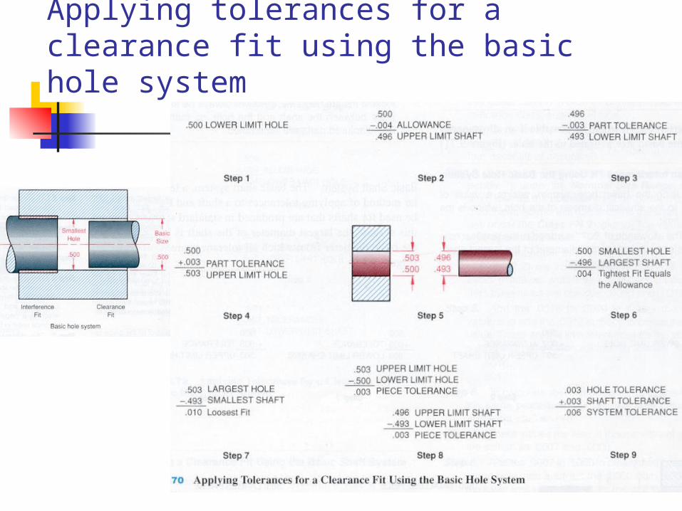
Applying tolerances for a clearance fit using the basic hole system
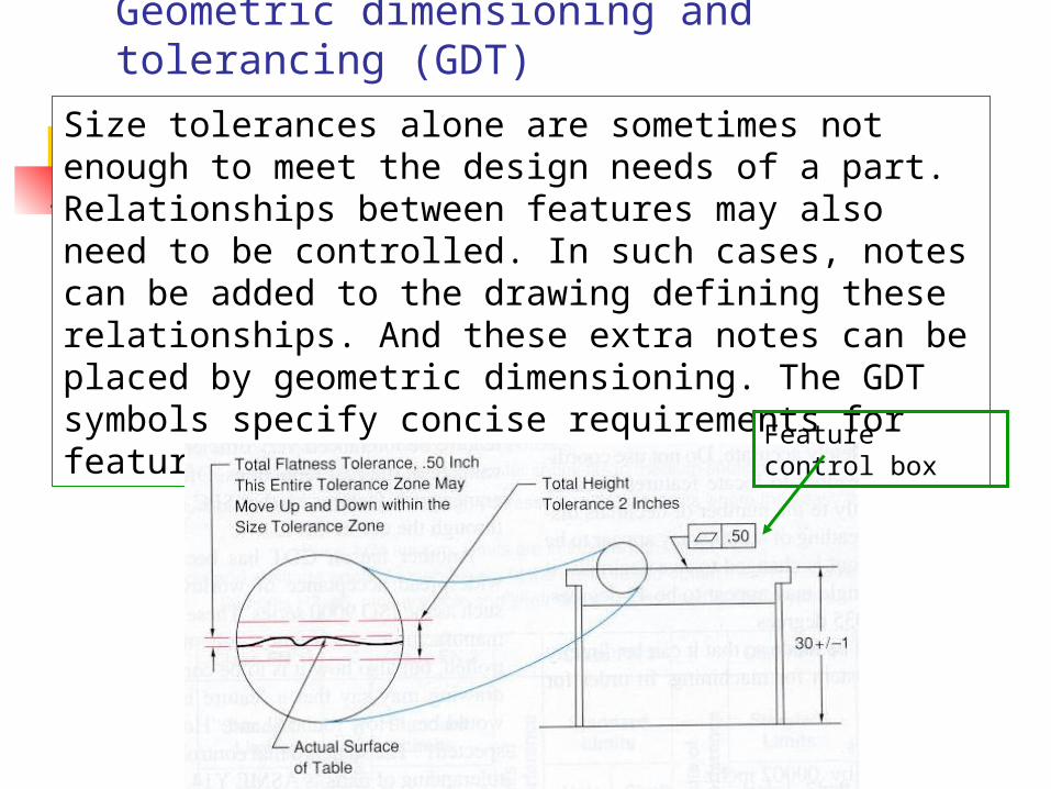
Geometric dimensioning and tolerancing (GDT)
Size tolerances alone are sometimes not enough to meet the design needs of a part. Relationships between features may also need to be controlled. In such cases, notes can be added to the drawing defining these relationships. And these extra notes can be placed by geometric dimensioning. The GDT symbols specify concise requirements for features.
Feature control box
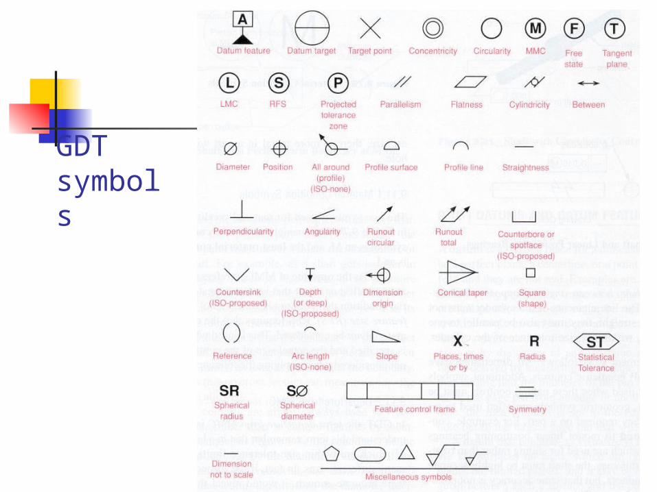
GDT symbols
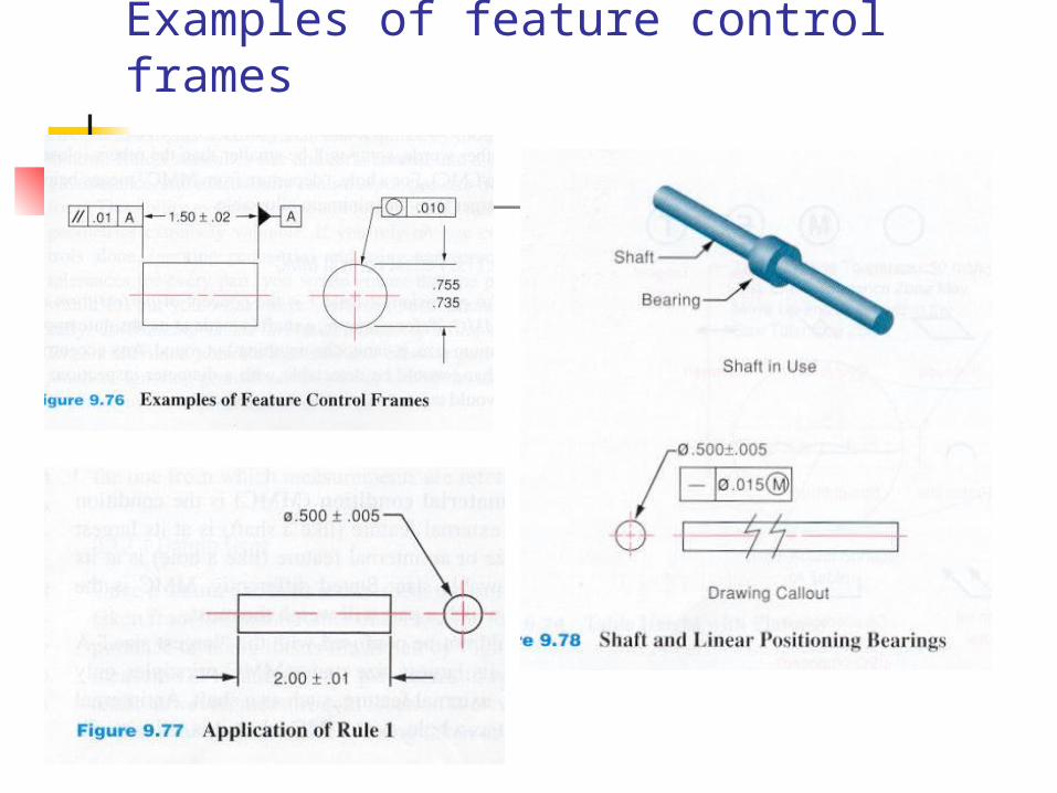
Examples of feature control frames


![SSppoojjkkyy RRAATTHHII JJAAWW--FFLLEEXX NN--FFLLEEXX … · 4.2 TOLERANCE OTVORU A DRÁŽKY PRO PERO TOLERANCE ULOŽENÍ OTVORU V NÁBOJI: Požadované uložení Díra [mm] Tolerance](https://img.pdfslide.tips/doc/110x75/5e18e4bd41a8c136c71922bb/ssppoojjkkyy-rraatthhii-jjaaww-fflleexx-nn-fflleexx-42-tolerance-otvoru-a-drky.jpg)