Embed Size (px)
Citation preview
THE VOICE OF THE NORTH AMERICAN CONVEYOR INDUSTRY
AGENDA OF THE CEMA ENGINEERING CONFERENCE
BUCKET ELEVATOR COMMITTEE MEETING
Tuesday, June 25, 2013 10:00 – 12:00 PM
A. Call to Order B. Attendance and Introductions C. Review of Last Meeting’s Minutes D. Approval of Agenda E. Old Business
1. Bucket Elevator Standards Review/approval of all the drafts submitted during the past year.
Each volunteer discuss the progress they have made on their chapter and plan to complete. What chapters will be ready by the CEMA Fall Meeting in September?
2. Report from Trevin Berger, Martin Sprocket & Gear and Bill Mecke, KWS Manufacturing, who were assisting to ensuring the project, stays on task.
3. A review of the Prospective Bucket Elevator Candidates was reviewed, with additions and deletions.
F. New Business
Do we continue the conference call as last year for a progress report from all volunteers if so how often.
G. Next Meeting – June 24, 2014 – La Playa Hotel, Naples, FL F. Adjourn Warren Knapp Bucket Elevator Committee Chair
Conveyor Equipment Manufacturers Association
THE VOICE OF THE NORTH AMERICAN CONVEYOR INDUSTRY
MINUTES OF THE 85th CEMA ENGINEERING CONFERENCE
Bucket Elevator Committee Meeting
LaPlaya Beach Hotel, Naples, Florida June 26, 2012
1. Call to Order / Roll Call:
Meeting convened at 11:30 am by Warren Knapp, Chair Roll Call: List of attendees attached.
2. Meeting Minutes Approval: Engineering 2011 meeting minutes approved by consent.
3. Old Business: • Bucket Elevator Standards • It was decided by the Committee that review/approval of the followings drafts: Table of
Contents, Chapter 1, Chapter 2 and Chapter 3 would not be reviewed at this meeting.
4. New Business: • The Committee decided that they would have attendees of the meeting volunteer to review
and develop each chapter under the “Table of Contents”. Volunteers were recorded (see attached list) and were asked to review and/or develop their chapters and have a progress report ready by the CEMA Fall Meeting in September. A draft of what has already been provided will be sent to each volunteer. CEMA will assist in collecting data and provide a working page location on the website to facilitate progress on project.
• Trevin Berger, Martin Sprocket & Gear and Bill Mecke, KWS Manufacturing, will assist in ensuring the project stays on task.
• The Committee decided that the name of the book will be “Bucket Elevator Design Application”
• A conference call will be set-up for the first (1st) week of September for a progress report from all volunteers.
• A review of the Prospective Bucket Elevator Candidates was reviewed, with additions and deletions.
Next Meeting scheduled for September 19, 2012, O’Hare Hilton. Meeting adjourned at 12 noon. Warren Knapp, Chair Attachment1 – Volunteer Review List for Bucket Elevator Design Application Attachment 2 – Suggested Reference Material Attachment 3 – DRAFT of Bucket Elevator Design Application
Conveyor Equipment Manufacturers Association
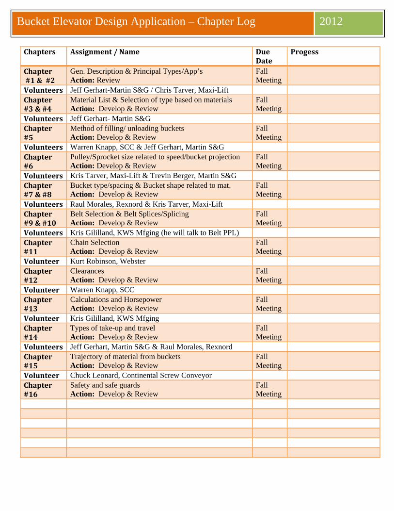
2008 Bucket Elevator Design Application – Chapter Log 2012
Chapters Assignment / Name Due Date
Progess
Chapter #1 & #2
Gen. Description & Principal Types/App’s Action: Review
Fall Meeting
Volunteers Jeff Gerhart-Martin S&G / Chris Tarver, Maxi-Lift Chapter #3 & #4
Material List & Selection of type based on materials Action: Develop & Review
Fall Meeting
Volunteers Jeff Gerhart- Martin S&G Chapter #5
Method of filling/ unloading buckets Action: Develop & Review
Fall Meeting
Volunteers Warren Knapp, SCC & Jeff Gerhart, Martin S&G Chapter #6
Pulley/Sprocket size related to speed/bucket projection Action: Develop & Review
Fall Meeting
Volunteers Kris Tarver, Maxi-Lift & Trevin Berger, Martin S&G Chapter #7 & #8
Bucket type/spacing & Bucket shape related to mat. Action: Develop & Review
Fall Meeting
Volunteers Raul Morales, Rexnord & Kris Tarver, Maxi-Lift Chapter #9 & #10
Belt Selection & Belt Splices/Splicing Action: Develop & Review
Fall Meeting
Volunteers Kris Gililland, KWS Mfging (he will talk to Belt PPL) Chapter #11
Chain Selection Action: Develop & Review
Fall Meeting
Volunteer Kurt Robinson, Webster Chapter #12
Clearances Action: Develop & Review
Fall Meeting
Volunteer Warren Knapp, SCC Chapter #13
Calculations and Horsepower Action: Develop & Review
Fall Meeting
Volunteer Kris Gililland, KWS Mfging Chapter #14
Types of take-up and travel Action: Develop & Review
Fall Meeting
Volunteers Jeff Gerhart, Martin S&G & Raul Morales, Rexnord Chapter #15
Trajectory of material from buckets Action: Develop & Review
Fall Meeting
Volunteer Chuck Leonard, Continental Screw Conveyor Chapter #16
Safety and safe guards Action: Develop & Review
Fall Meeting
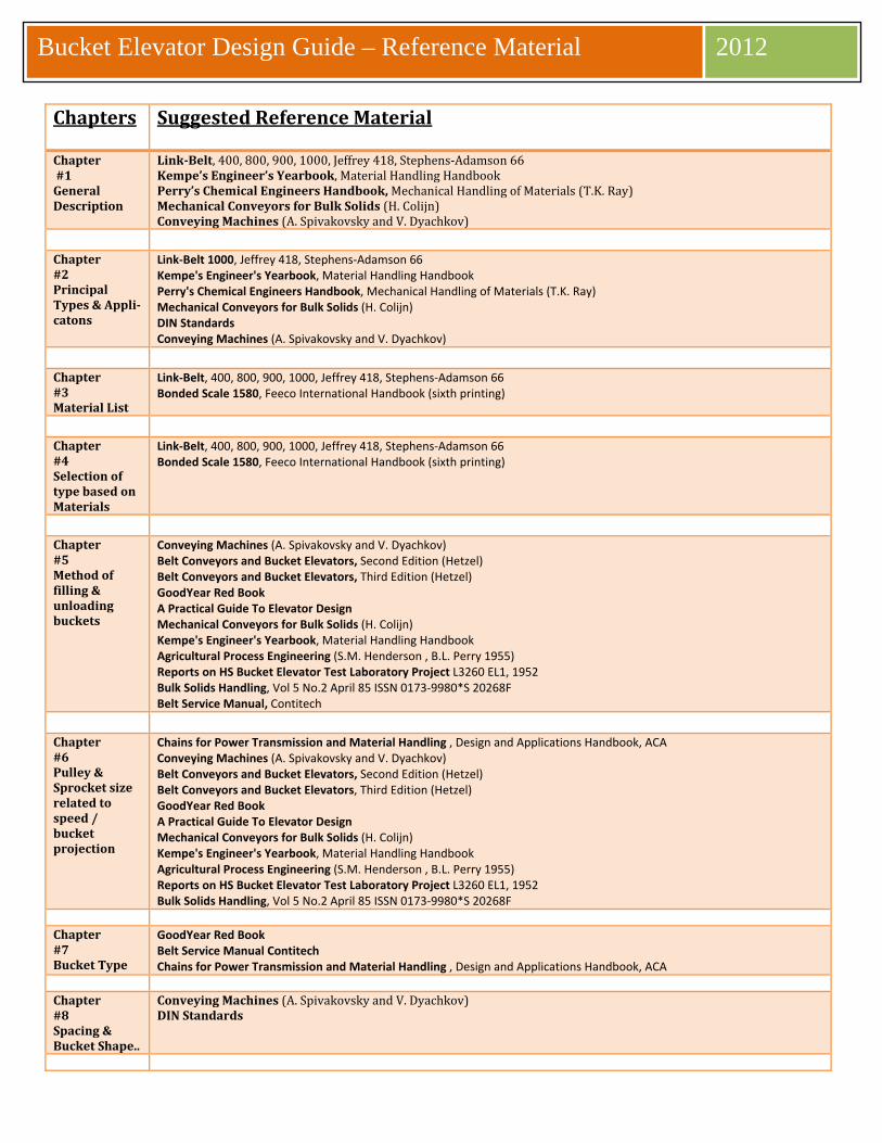
2008 Bucket Elevator Design Guide – Reference Material 2012
Chapters Suggested Reference Material
Chapter #1 General Description
Link-Belt, 400, 800, 900, 1000, Jeffrey 418, Stephens-Adamson 66Kempe’s Engineer’s Yearbook, Material Handling Handbook Perry’s Chemical Engineers Handbook, Mechanical Handling of Materials (T.K. Ray) Mechanical Conveyors for Bulk Solids (H. Colijn) Conveying Machines (A. Spivakovsky and V. Dyachkov)
Chapter #2 Principal Types & Appli- catons
Link-Belt 1000, Jeffrey 418, Stephens-Adamson 66 Kempe's Engineer's Yearbook, Material Handling Handbook Perry's Chemical Engineers Handbook, Mechanical Handling of Materials (T.K. Ray) Mechanical Conveyors for Bulk Solids (H. Colijn) DIN Standards Conveying Machines (A. Spivakovsky and V. Dyachkov)
Chapter #3 Material List
Link-Belt, 400, 800, 900, 1000, Jeffrey 418, Stephens-Adamson 66 Bonded Scale 1580, Feeco International Handbook (sixth printing)
Chapter #4 Selection of type based on Materials
Link-Belt, 400, 800, 900, 1000, Jeffrey 418, Stephens-Adamson 66 Bonded Scale 1580, Feeco International Handbook (sixth printing)
Chapter #5 Method of filling & unloading buckets
Conveying Machines (A. Spivakovsky and V. Dyachkov) Belt Conveyors and Bucket Elevators, Second Edition (Hetzel) Belt Conveyors and Bucket Elevators, Third Edition (Hetzel) GoodYear Red Book A Practical Guide To Elevator Design Mechanical Conveyors for Bulk Solids (H. Colijn) Kempe's Engineer's Yearbook, Material Handling Handbook Agricultural Process Engineering (S.M. Henderson , B.L. Perry 1955) Reports on HS Bucket Elevator Test Laboratory Project L3260 EL1, 1952 Bulk Solids Handling, Vol 5 No.2 April 85 ISSN 0173-9980*S 20268F Belt Service Manual, Contitech
Chapter #6 Pulley & Sprocket size related to speed / bucket projection
Chains for Power Transmission and Material Handling , Design and Applications Handbook, ACA Conveying Machines (A. Spivakovsky and V. Dyachkov) Belt Conveyors and Bucket Elevators, Second Edition (Hetzel) Belt Conveyors and Bucket Elevators, Third Edition (Hetzel) GoodYear Red Book A Practical Guide To Elevator Design Mechanical Conveyors for Bulk Solids (H. Colijn) Kempe's Engineer's Yearbook, Material Handling Handbook Agricultural Process Engineering (S.M. Henderson , B.L. Perry 1955) Reports on HS Bucket Elevator Test Laboratory Project L3260 EL1, 1952 Bulk Solids Handling, Vol 5 No.2 April 85 ISSN 0173-9980*S 20268F
Chapter #7 Bucket Type
GoodYear Red Book Belt Service Manual Contitech Chains for Power Transmission and Material Handling , Design and Applications Handbook, ACA
Chapter #8 Spacing & Bucket Shape..
Conveying Machines (A. Spivakovsky and V. Dyachkov)DIN Standards
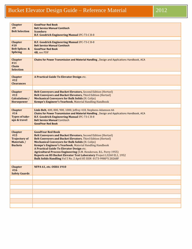
2008 Bucket Elevator Design Guide – Reference Material 2012
Chapter #9 Belt Selection
GoodYear Red Book Belt Service Manual Contitech Scandura B.F. Goodrich Engineering Manual IPC-73-C B-8
Chapter #10 Belt Splices & Splicing
B.F. Goodrich Engineering Manual IPC-73-C B-8Belt Service Manual Contitech GoodYear Red Book 4B, see PDF
Chapter #11 Chain Selection
Chains for Power Transmission and Material Handling , Design and Applications Handbook, ACA Chapter #12 Clearances
A Practical Guide To Elevator Design etc. Chapter #13 Calculations / Horsepower
Belt Conveyors and Bucket Elevators, Second Edition (Hertzel)Belt Conveyors and Bucket Elevators, Third Edition (Hertzel) Mechanical Conveyors for Bulk Solids (H. Colijn) Kempe’s Engineer’s Yearbook, Material Handling Handbook
Chapter #14 Types of take-ups & travel
Link-Belt, 400, 800, 900, 1000, Jeffrey 418, Stephens-Adamson 66Chains for Power Transmission and Material Handling , Design and Applications Handbook, ACA B.F. Goodrich Engineering Manual IPC-73-C B-8 Belt Service Manual Contitech GoodYear Red Book
Chapter #15 Trajectory of Materials / Buckets
GoodYear Red Book Belt Conveyors and Bucket Elevators, Second Edition (Hertzel) Belt Conveyors and Bucket Elevators, Third Edition (Hertzel) Mechanical Conveyors for Bulk Solids (H. Colijn) Kempe’s Engineer’s Yearbook, Material Handling Handbook A Practical Guide To Elevator Design etc. Agricultural Process Engineering (S.M. Henderson, B.L. Perry 1955) Reports on HS Bucket Elevator Test Laboratory Project L3260 EL1, 1952 Bulk Solids Handling Vol 5 No. 2 April 85 ISSN 0173-9980*S 20268F
Chapter #16 Safety Guards
NFPA 61, etc. OSHA 1910
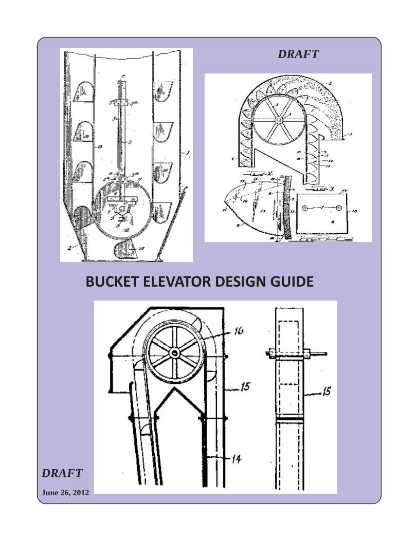
DRAFT
BUCKET ELEVATOR DESIGN GUIDE
June 26, 2012
DRAFT
DRAFT
DRAFT
TABLE OF CONTENTS
PROPOSED TABLE OF CONTENT FOR BUCKET ELEVATORS
Introduction / History of Bucket Elevators
♦ 1. General Description
♦ 2. Principal Types and Applications of Bucket Elevators
♦ 3. Material List
♦ 4. Selection of type based on material
♦ 5. Method of Filling and Unloading of Buckets
♦ 6. Pulley / Sprocket size related to speed and bucket projection
♦ 7. Bucket type and Spacing
♦ 8. Bucket Shape related to Material
♦ 9. Belt selection
♦ 10. Belt Splices and splicing
♦ 11. Chain Selection
♦ 12. Clearances
♦ 13. Calculations and Horsepower
♦ 14. Types of take-up and travel
♦ 15. Trajectory of material from buckets
♦ 16. Safety and safe guards.
DRAFT
History of the Bucket Elevator
Bucket elevators are the most efficient means of elevating free flowing granular materialsand most materials even some sticky materials.
Bucket elevators of the centrifugal discharge are normally used and most are of belt type.Friable materials are best handled in continuous bucket elevators that operate at lowspeeds. The continuous buckets are discharged by gravity on the back of the precedingbucket while passing over the head pulley, thus reducing breakage caused by thecentrifugal force discharge of a centrifugal elevator. Bucket elevators usually require theleast amount of horsepower for vertical conveying of any conveying system.
The bucket elevator has been in used in the USA for many over a century. In addition, forthe most part the same basic design has been followed. Leonardo da Vinci in the 1400’sbelieved art was the chief instrument of man’s search for knowledge. The ancestors of themodern day bucket elevator first appeared at about 230 BC these devices werepredominantly used for elevating water by the use of pots attached to an endless rope. It isbelieved that the water used for the famous Hanging Gardens of Semiramus was broughtup to a height of 300 feet by this means. A remarkable achievement, having regard to thefact, that modern elevators rarely work to heights greater than 150 feet. Since this time,the bucket elevator has gone through a period of evolution. There was a flourish of activityin elevator design and patents between 1850 and 1930. Since that time there has been verylittle new work or mathematically supported designs developed. As Leonardo da Vinic said“Art is never finished, only abandoned”, this can be said for the design of bucket elevators,development has been abandoned. There are few in depth texts on bucket elevator design and/or proper application. This istrue for all types of bucket elevators. The following are example of early elevator patents
Examples to be added later.
DRAFT
Bucket Elevators
2.1 GENERAL
A bucket elevator consists of a series of uniformly fed buckets mounted on an endless chain or belt whichoperates over head and foot wheels. The buckets are used to elevate (usually vertically) pulverized, granular, orlumpy materials. The material is received at the boot, raised and then discharged by passing over the headwheel at the top, into a discharge chute. Generally this mechanism is enclosed in a casing, especially the headand foot sections. Some elevators are self-supporting, but more often they are supported by, or at least bracedagainst, a structural steel frame. Bucket elevators will be discussed under the seven headings listed below.Inclined elevators, which were seldom enclosed, were popular for handling crushed stone, but because of OSHAregulations, will probably go out of use (see figure 1.1).
2.1.1 Centrifugal-Discharge Bucket Elevator
In centrifugal-discharge bucket elevators, the material to be elevated is dug out of the boot and discharged bycentrifugal force. They are comparatively high-speed elevators, used where the percentage and size of lumps areat a minimum.
2.1.2 Continuous Bucket Elevator
In continuous bucket elevators, buckets closely spaced on chain or belts are designed so that material isloaded directly into the buckets, usually through a loading leg, instead of being scooped up in the boot.Discharge over the head wheel is accomplished by transfer of material from the discharging bucket to the frontof the preceding one, which acts as a moving chute to the fixed discharge chute. Sometimes styled SuperCapacity, large-capacity continuous-bucket elevators are made with specially designed steel buckets attached attheir sides to double-strand long-pitch steel chain.
2.1.3 Positive-Discharge Bucket Elevator
The positive-discharge bucket elevator should be considered where materials tend to stick in the buckets orwhere fluffy materials are handled. With its buckets at intervals on double-strand chain, this elevator picks up itsload in the boot (as does the centrifugal-discharge type), but because of its lower speed, does not depend uponcentrifugal force to discharge material from the buckets. The buckets are completely inverted by snubbing thechains after they have passed over the head wheels, giving them opportunity for complete discharge atrelatively slow speed and horizontally as a scraper flight conveyor. Steel buckets, rigidly attached to double-strand steel bar-link, long-pitch roller chain, travel along a continuous steel trough on the horizontalloading run, picking up the material en route. At the lower comer upturn, a special steel comer trough isused to fill the buckets before starting their vertical run. At the upper comer, another curved comer pieceis provided to transfer the load to the upper horizontal run, from where the “material can be discharged atintervals through openings provided with slide gates. The discharge of the bucket is steep enough to empty asit passes over the discharge opening. It is seldom used, because it is slow and expensive.
2.1. 4 Internal-Discharge Elevator
The internal-discharge elevator works well in continuously gently handling small bulk articles such asbolts or small castings. Buckets are loaded internally in casing from a chute extending through one sideof the casing. Because of their infrequent use, no further space is devoted to them.
DRAFT
2.1.5 Bucket Elevator on Incline
A bucket elevator can operate on an incline, if the chain is guided. If the angle of inclination is over 45°from the vertical, it is better to use an apron or pan conveyor.
2.1.6 Centrifugal vs Continuous-Bucket Elevators
Normally a centrifugal-discharge bucket elevator can handle lumps up to 1 in. if they are not more than10% of the required capacity. When the lumps are more than 10%, the continuous buckets should beused. Because of its lower speed and methods of loading, the continuous-bucket elevator will causeless breakage of fragile materials. Belts should be used for corrosive material. If chain is used, it shouldbe heat treated, and Everdur bronze pins and stainless-steel S-shaped cotter pins should be specified.Some material may require alloy buckets. If the material is damp or wet, even if the capacity is small, adouble-strand super-capacity continuous-bucket elevator, equipped with flat bottom buckets, or apositive-discharge bucket elevator should be used. If there are fines present, there is the possibility ofthe fines sticking to the bottom.
2.1.7 Preliminary Selection of Type
Table 2.1 tabulates the properties of the various types of elevators.
2.2 CASING
The elevator is usually enclosed in a steel casing, to provide a means of support and as a matter ofsafety and dust retention. A casing can be made dust-tight, either by using a sealing medium, orcontinuously welding the comer angles to the plate. Figure 2.2 shows details of dusttight construction.These casings are regularly made with inspection cleanout doors. For free-standing elevators, structuralconsiderations, such as strength of the sections and the size and number of anchor bolts to resist wind,often will dictate the narrow dimension of the casing and its composition. Steel plates with cornerangles provide a substantial support to the complete unit. Elevators are usually self- supporting andfree standing up to 30 ft, with some even up to, say, 60 ft above the boot with special design . Abovethese heights, the casing are self-supporting but not free standing, and must be braced against thebuilding or silo for heights over 30 ft. In some cases, the head shaft supporting the complete chain andbuckets is mounted on building steel, to take the load off the casing, which then acts simply as a cover,carrying only its own weight. Very large drives (motor and speed reducer) should be supported directlyon the building steel or tower, rather than on the elevator casing.
2.2.1 Drives
A V -belt drive from the motor to speed reducer is recommended. Action is similar to that of a shearpin: the belt comes off the sheaves should anything become jammed. Intermediate sections ofelevators are usually made of 12, 10 or 7 gauge steel, in sections 8-1O-ft long. These should bedesigned using cold formed thin shell analysis. The casing acts as a column, and can support a veryheavy vertical load. For easy inspection inside the casing, large inspection doors are usually placed inthe intermediate section above the boot, or about 3 ft above the floor in a section that passes througha floor. Special consideration of casings with inspection or service doors to ensure the structuralintegrity is maintained. The head sections of elevators usually are designed with the hood or top coversplit, so the two parts can be easily removed for inspection. A hinged ‘door can also be located on topof the cover, or on the inclined portionforming part of the chute, both for inspection and when necessary for watching the discharge ofmaterial or servicing the throat plate. For servicing the elevator, a casing should be at least 6 in. widerthan the bucket. For tall elevators, say over 75 ft, a bigger allowance should be made to prevent thebuckets from slamming against the sides of the casing. For handling explosive materials, refer to laterchapter.
DRAFT
2.2.2 Inspection Doors
An example of a dust tight inspection door is shown on figure 2.3. When handling fine and dustymaterial, it is a necessity. This can be placed anywhere in the elevator casing, particularly in the headand boot sections. Most manufacturers have their own design, and should be allowed to use it foreconomy.
2.3 ELEVATOR PITS
Elevators generally are placed in pits, although this should be avoided wherever possible. If pits mustbe used, ample space should be provided in both length and width to allow for maintenance. A goodrule is to provide a minimum clearance of 24 in. on one side and boot shaft length plus 24 in. on theother side of the elevator. The feed inlet point of the continuous-type elevator is somewhat higher thanthat of the centrifugal elevator, necessitating a deeper pit when located below ground level.
2.4 BOOT SECTION
Steel elevator boot sections should be made of not less than 10 ga steel for elevators under 30 ft (thosewith very low capacity) and 0.25 in. for elevators above 30 ft. In elevators the boot section supportseither part or all of the entire unit. Removable doors and side plates can be installed in boot sections,to make it easier to clean out the boot by hand, when and if required. In industries where productscannot be mixed or contaminated, the boots have to be cleaned out after each operation or run. Insome cases, the entire sides of the casing are made re-movable for cleaning. Normally, the location ofthe point of bottom of the inlet in a boot occurs at the center line of the boot pulley in its upper mostposition or between 4 in. and 6 in above this point for centrifugal types, Two bucket spaces generallyabout 20-26 in. for continuous types, above the centerline of the boot or shaft in its highest position.An allowance of at least 6 in. below the buckets, with the take-up in the lowest position, should bemade forcleaning-out purposes.
2.5 HEAD SECTION
Figure 2.5 shows an elevator head section with head take-up and one method of supporting the drivemechanism. This is a self-supporting casing. Normally, the point of discharge is located as shown on thefigure; that is, 6 in. below centerline of the head shaft, projected on a 45° line downward. An adjustablethroat plate in the bottom of the discharge spout is usually used to prevent materials from falling downthe casing to the boot.
When handling very fine and dry materials, the 6 in. vertical dimension should be made 12 in. Thisprovides more time for the buckets to discharge the fine material. In some cases, the head shaftsupporting the chain and buckets is mounted on building steel. The casing then acts as only a cover,with no machinery load on it.
The head sections of elevators are made with either fixed shaft or take-up shaft. Covers should bemade split where possible so that the two parts can be easily removed for inspection and maintenance.A door opening can be located on top of the cover or the inclined part of the discharge spout, both forinspection and for checking the discharge of material (see figure 2.6). For dust takeoff, one connectioncan be made in the boot section just above the loading hopper, and one at the discharge chute or atthe top of the elevator. Provide pipe connection at the top of each. In handling dusty material, a goodhead shaft dust seal should be usedto prevent the dust from coming out of the head section of the elevator casing.
DRAFT
2.6 PLATFORMS AND LADDERS
On vertical elevators of any height where the head shaft cannot be easily reached by maintenancepersonnel, it is necessary to include a standard steel ladder attachment to the casing, including a steelsafety guard beginning 7 ft from lower floor level, and extending to a steel platform. This platformshould be of ample size for working on, with the floor of expanded metal, grating, or diamond floorplates. In areas where considerable snow falls and the elevator is located outdoors, an open gratingshould be used to rid the platform of ice and snow and to prevent slipping. Intermediate platformsshould be provided every 30 ft or so. Handrails should be of standard design, made of angles or piping as approved by safetyregulations. Steel toe plates about 6-in. high must be included to prevent a person’s feet frommoving off the platform. A hoist beam can be provided about four feet above the top of the elevatorcasing on line of the head shaft, to assist in maintenance work. A V-belt drive from motor tospeed reducer is preferred by some because the belt will come off the sheaves should anything becomejammed.
2.7 BUCKETS
Malleable iron buckets, either continuous type or type AA, have a Brinell hardness of about 120.Promal buckets are heat-treated, malleable-iron buckets with a Brinell hardness of 190. Bucketsshould be at least four times the size of the lumps, to get required capacity and avoid spill. For awidth of bucket greater than 16 in., two strands of chain (or a belt) must be used. Charcoal,especially, requires wide buckets on two strands of chain. All steel buckets today are made ofwelded construction, either spot welded or continuously welded, depending on the fineness ofmaterial handled. For abrasive material, heat-treated, malleable-iron or cast buckets should beused. High-density polyethylene bucket that is used primarily in the handling of grain, feed,cottonseed oil, salt production,soybean oil processing, and similar products. These buckets are rustproof, shatterproof, sparkproof, and self cleaning. They weigh a third the weight of steel buckets and a fifth of malleableiron. There also are Low-Profile (LP), designed to increase the overall capacity by closing up thespacing on the belt. Care must be given to the selection and use of a LP bucket, it is best to useone that has been specifically design for this application and not just a truncated standard. In lightfluffy material, four or five holes, about 1/4 in. in diameter in the bottom and 1/4 in. diameter inthe sides near the bottom, are placed to break the suction or vacuum created by the speed of thebucket in picking up the load in the boot. In polyethylene or other similar material buckets these holeneed to be larger in diameter.Without these holes, the light materials usually stay in the bucket and go down to the boot again,often piling up and causing an undue strain for the buckets to pick up and, incidentally, increasing thehorsepower required. Very little if any capacity is lost through the holes. In handling hot cement orgypsum, at 200-300oP, the holes in the bottom of the bucket help cool the material. The holes can beused for material at higher temperatures, and the cooling can be augmented by introducing outside airinto the casing. Alternating buckets are used on wide belts to obtain a better pickup in the boot of theelevator, and to preventany possible flooding of the boot with an avalanche of material coming to it. With a single bucketextending across a wide belt and spaced apart at varying intervals, a slight void space could result asthe buckets are turning around the foot pulley. With a continuous feed, the material would tend to pileup and finally stall the elevator (see figure 2.9). Buckets are discussed further under each type ofelevator.
DRAFT
2.8 CHAIN
Malleable chains are made with a Brinell hardness of about 120. If necessary, the chain can be mademore tough by processing the malleable iron. When handling abrasive materials such as sand, gravel,stone, or alloys, toughened malleable iron should be used (refer to paragraph 3.8.3).
Different chain manufactures have hardened chain each has different names and processes to createthis chain in general they all are about a Brinell 190 and have a gain of about 25% in ultimate strength.It is almost impossible to get a Brinell hardness much above 190 by heat treatment. For high elevators,say, 75 ft or over, it is also advisable to use two strands of chain. In that case, the specifications shouldrequire the strands to be matched and tagged right- or left-hand, although they are not actually right-or left-hand design. The two strands of chain are rigidly attached to the bucket and no two chainsstretch alike during operation. To meet this specification, the manufacturer will shop-assemble thesestrands of chain, to make sure that the attachments are opposite each other and to tag each strandproperly. If the erection is properly done, the buckets will be straight, even if the attachments areslightly off. On double-strand chains, some preference has been expressed for the use of 6-in. pitchinstead of the standard 12-in. pitch, with the bucket attachments every other pitch. This is done to runthe chain more smoothly going over the head sprockets. While it is true that by shortening the pitch,the chain will follow more closely to the circumference of the sprocket, it is doubtful that the extraexpense can be justified. Where the pitch is 18 in., a 9-in. pitch may be justified. The selection of thetype of chain, that is, malleable or steel combination, is dependent on the type of material to behandled, capacity required, type of duty (continuous or intermittent), and height of elevator. Class Ccombination chains are economical for general elevator service. SBS bushed chains are widely used forheavy duty and high elevators or those handling abrasive materials. A variety of chain is available andshown in manufacturers’ catalogs. Those most commonly used are shown in tables 3.2 and 3.3.Basically, however, the SBS-110 and SBS-102B are easy to obtain and have proved themselvessatisfactory in most installations. SBS and C combination chains are used in elevators. For handlinggritty and abrasive materials and in high vertical elevators, SBS chain is preferred. Class C combinationchain is less expensive, and is used on high vertical elevators handling aggregates, cement, and similarproducts. For other chains refer to table 2.3.
2.8.1 ServiceFactor
Here are summarized service factors for only those items that are normally involved in elevator andconveyorwork:
Uniformly loaded: 1.0Not uniformly loaded: 1.3Reciprocating conveyors: 1.5
Multiple Strand Factor2 strands: 1. 7
2.8.2 Recommended Speeds
The recommended speeds for various types of elevators are shown in table 2.1. For the maximumspeeds of allconveyor and elevator chains based on the number of teeth in the driving sprocket, refer to tables 1.5and 1.6.
DRAFT
2.8.3 Chain versus Belt
Choosing between chain and belt as an elevating medium depends upon the characteristics of materialhandled. Where the temperature of the belt is likely to exceed about 250°F, it is safer to use chain, andselect the best quality obtainable for the service. Hot materials up to 450°F (232°C) can be handled incontinuous buckets mounted on standard chain. If the temperature goes to 600°F (315°C), special steelbuckets mounted on hardened malleable chain should be used. Most malleable or steel chains willstand up to 600°F (315°C). Above 600°F, heat-treated alloy chain must be used. There are high-temperature belts on the market which may be used under certain conditions. It is advisable to consultwith the belt manufacturer.A number of manufactures offer a Wing-Type Pulley. These pulleys are installed on the boot or footshaft and are usually self-cleaning, offering maximum protection from belt damage as a result of lumpsor foreign material under belt. In this case, it is usually better to use chain, Whatever type of equipmentis used, due consideration should be given to the lift factor. The lowest initial cost frequently becomesthe more expensive in the long run. Most materials with lumps up to 2 1/2 in. can be handled withchain.Abrasive materials, such as sand and abrasive grain, should be handled by belt instead of chain becausethe fine particle size could easily get into the chain joints and cause rapid wear. If any of this class ofmaterial should be damp or wet, the belt may slip on the head pulley unless lagged with a herringbone-cut-groove rubber cover. Belts should also be used for corrosive material. If chain is used, it should beheat-treated. Corrosive materials may require alloy buckets, and Everdur bronze pins and stainless steelS-shaped cotter pins should be specified. Usually when belts are used, on a continuous elevator,especially outdoors, the pulley must be lagged, or covered with a rubber covering vulcanized, slide orrough-top or with herringbone grooves cut into it, to get good contact with the belt.When selecting a belt as an elevating medium, materials that pack and tend to build up between the belt andpulley, as well as. rough or jagged particles that damage the belt by becoming lodged between buckets and belt,should be avoided. To some extent, these difficulties are alleviated through the use of spacers between thebucket and belt and wing pulleys on the foot or boot shaft. In handling lumps with sharp edges, it is usuallybetter to use chains. These lumps may become lodged between buckets and belt,resulting in damage to the belt as the material is picked up in the boot, or as the belt passes over the headpulley.
2.9 TRACTION WHEELS AND SPROCKETS
For general-purpose installations where there are no frequent shock loads, the arm or spoke-typesprocket is used. Plate-center sprockets (arm sprockets filled in to make a solid center) are used whereshock loads are anticipated or where the maximum allowable chain pull on heavy-duty chains isrequired. Split sprockets can be furnished in arm or plate-center sprockets to facilitate mounting orremoving them from the shaft without disturbing the bearings or the shaft itself.
Hunting-tooth sprockets have an odd number of teeth, with the pitch of the teeth one-half that ofthe chain. Because of the odd number of teeth, the chain barrels contact the intermediate teeth aftereach revolution of the sprocket. Therefore, each tooth has one-half the number of contacts that itwould have on a regular full pitch sprocket over any period of time, thus increasing the life of the wheelon high-speed shafts.Traction wheels (without teeth) and sprocket wheels also are made with cast-ironsolid-hub centers, and with sectional bolted rims that can be removed without disturbing the hubs inany way, and replaced quickly with a minimum of down time. There is a growing tendency to usetraction wheels at the bottom instead of sprockets. Traction wheels cannot be used at the foot, as thechain will slip off. There is always traction at the head because of the load. When the elevator clogs, thetraction wheel will slip. It should be used for elevators 50 ft and over, and sometimes over 35 ft whenhandling abrasive materials. Some prefer to use the same sprockets at foot and head so that, in anemergency, the foot sprocket can be used at the head, if the teeth are not too badly worn. Somemanufacturers of sprockets have developed a method of casting chrome-nickel inserts into the rim ofthe sprocket to provide great strength, toughness, and abrasion-resisting qualities. Split (two-piece)sprockets, bolted together at the rims and at the hubs, also help to reduce labor costs.
DRAFT
2.10 TAKE-UPS
Normally, elevators have the screw-type take-up on the foot or boot shaft unless space does notpermit. If it isnecessary to place the screw-type take-up on head shaft, the centers of the bucket elevator should notexceed 90ft, because the total weight of chain (or belt) plus buckets and load in buckets on up or carry side, ishangingon the take-up screw in tension (see figure 2.11). Wherever a head take-up is used, the next larger sizedheadshaft from that recommended should be used, as the vibration is transferred to the head shaft throughthe pickup in the boot.
Gravity takeups are used on many elevators, particularly on powdery or aerated material such as cement,lime, and gypsum. A softening effect is encountered at the pickup which must be absorbed by thisfloating take-up. The frame supporting the shaft and wheel simply rides up and down in angle or channel guides,attached to the inside of the casing. Usually there is enough weight in the complete take-up to keep itin position but, if necessary, additional weight can be placed on the movable steel or cast steel frame (seefigures 2.12 and 2.13). The sprocket, or traction wheel, runs loose on the shaft and is kept in place bysafety collars on each side of the hub. The diameter of the hub is much larger than necessary, so that inthe event the bore of the wheel becomes sloppy, instead of discarding the wheel, it canbe bushed. No lubrication is provided since the shaft is pinned and does not rotate. Figure 3.14 shows ahead shaft equipped with a differential band brake (back-stop) that is used to prevent the up, orcarrying; side from running backward in the event of a power interruption. The backward drift isexpected to be less than 2 ft and, upon resumption of power, the brake is immediately released.External back stops are preferred on large horse power units over ones internal to the reducer.
2.11 HORSEPOWER
There are several formulas in use for computing horsepower. In general, they are based on twoprinciples:1. The weight of the material in the loaded buckets. The weight of the chain or belt and the weight
of the buckets on the up-run is balanced by the weight of the chain or belt and the buckets on thedown-run.
2. An allowance is made for the extra load at the boot, and for boot pulley friction. From tests, thevalue has been assumed to be the equivalent of 250-500 lb of ‘load. Thus, for continuous buckets, itwill be ( 10 X 12 X w
m) / s, and (30 X 12 X w
m) / S for centrifugal discharge (spaced) bucket elevators.
2.12 STANDARD DESIGNS
Standard designs of elevators are given in tables 2.4, 2.5, and 2.6. It is not advisable to use the tablesfor finaldesign. The weight of the buckets and their capacity are always subject to change, because of theabrasivenessof the material, the weight of the material, the size and percentage of lumps, the fluidity of thematerial, the rateof delivery of the material to the elevator, the moisture content of the material, and the speed of thebuckets.
DRAFT
2.13 BELTS
The widths of the belts for various size buckets is given in table 2.5. It is good practice to use no fewerthan fourplies, even for the lightest loads. For preliminary design purposes, assume the weight of the belt andattachments to be 6.5lb / ft of belt width.
2.14 CENTRIFUGAL-DISCHARGE BUCKET ELEVATORS(Vertically Spaced)
2.14.1 General
A centrifugal-discharge elevator is designed to operate at a high speed, usually from 185 ft to 300 ft ormore per minute, picking up material in the boot, as it is fed to it, and discharging the material bycentrifugal force out of the buckets, as they pass over the head sprocket or pulley into a chute attachedto the elevator casing. For very fine materials, similar to gypsum and cement ( - 10 mesh to 200 mesh),experience has shown that the speed can be reduced to about 185 fpm. The head wheel diameter willvary between 20 in. and 31 in. Speed is critical.Travelling slower than recommended may not allow material to be discharged by centrifugal force, andmaterial may come back on the return run. Travelling faster than recommended may cause material tohit the hood and bounce back down the return run. The size of the head wheel (D, in ft) and the rpm ofthe head shaft may vary, but the speed of the elevator (fpm = D X rpm) must be maintained in order toavoid backlegging (return of material on the down run), regardless of the required capacity. For grain,cottonseed, wood chips, and other lightweight materials, however, the double-leg casing elevator,having buckets mounted on a belt and travelling at higher speeds, is frequently used. Bucket speeds forsuch units range between 350 fpm and 750 fpm, the head wheel diameter ranges from 24 in. to 84 in.,and the spacing of the buckets will vary from bucket projection plus 2 in. to 24 in. The capacity will varybetween 14 tph and 1500 tph for material weighing 50 PCF. This type of elevator usually is enclosed in asteel casing to provide a means of support, and as a matter of safety and dust retention.
On a centrifugal-discharge chain elevator, inclined about 30° from the vertical, the single strand ofchain can be supported on the up, or carrying side, on single flanged rollers spaced 6-8 ft on centers.The return run can sag if there is plenty of clearance; if not, the return run can be supported by havingthe buckets slide on two angles, forming a track, to keep the return run in the proper path (see figure 2.15).
A centrifugal-discharge elevator will handle almost any kind affine or small lump materials. Itoperates well when handling dry and free-flowing products such as grain, coal, petroleum coke, sand,sugar, salt, chemicals, limestone dust, gypsum, sulfur, and cement. The size of the lumps should be 2 in.and under, with the greater part of the volume under 1 in. If there are many 2-in. lumps, the bucketsshould be at least 12-in. wide, regardless of capacity. This type of elevator should not be used formaterials containing over 10% to, say, 15% of lumps, because of the possibility of plugging in the boot,and the difficulty in retaining lumps in the bucketsas they travel upward. It should not be used where breakage of material is to be avoided. Continuous-bucket elevators should be used instead.
2.14.2 Buckets
The size of the buckets ranges from 6 in. X 4 in. (6-in. long with 4-in. projection) to 24 in. X 15 in. Thespacing of A or AA buckets can be between 13 in. and 24 in., depending on capacity. The A buckets aresimilar to AA, but are built lighter and of smaller capacity. They are seldom used. The buckets may bemalleable or cast iron, steel, or plastic. The buckets are normally attached to a single strand of chain orbelt with what are known as K attachments, spaced at intervals. The K -1 attachment has 2 holes, andthe K-2 attachment has four holes. The manufacturers’ catalogs give the type of attachment to be usedfor fastening to the back of the bucket, and thepunching required for the belt. It depends on the minimum and maximum size of the bucket (refer to
DRAFT
table 2.7). Since the plastic buckets are not adapted for hard digging in the elevator boots, it isadvisable to place one style AA bucket (malleable iron, reinforced digging edge) on every sixth to eighthattachment. This bucket will clean a path through the caked material in the boot of the elevatorhousing, so that the plastic buckets do not have to dig, only elevate. This malleable iron bucket Shouldbe inspected at regular intervals for wear and corrosion.
2.14.3 Inclined Elevators
A centrifugal-discharge elevator, equipped with either chain or belt, can operate on an incline at thesame speeds as vertical elevators by welding or attaching steel fiats on back of buckets, to ride on steelangle track attached to elevator casing sides, for both carrying and return runs. The use of this steelangle track on return run prevents sagging ‘of chain and bucket line, saving much space. A belt can beused instead of a chain, when necessary. Open inclined continuous bucket elevators are used in spite ofthe difficulties during rainy weather when the materials hang in the buckets and do not dischargeproperly. These elevators use either chain ‘or belt. Normally, units of this kind are inclined 30° from thevertical, allowing the return run to sag (usually clearance permits this), and are not covered in any wayor protected from the weather. The machinery for these elevators can be mounted on structuralframes. The open inclined elevator are very rare because of the problems of being OSHA compliant.
2.14.4 Centrifugal-Discharge Elevator Buckets
The edges of all these buckets are reinforced for digging, and the bottom of these buckets is rounded.The various types of buckets used in centrifugal discharge elevators are described below.
1. AA buckets are made of malleable iron for chain or belt mounting, They have a reinforced lip fordigging, They are the most common type in use for centrifugal discharge elevators.
2. AA-RB buckets are the same as the AA buckets, except that the edges are thicker, They are usedfor heavy service, and for abrasive materials.
3. AC buckets (table 2.12) are made for chain mounting. The hooded back allows a closer spacingof buckets.
5. B buckets (table 3.13) are cast malleable iron buckets for chain or belt mounting. They are usedon inclined elevators for handling coarse materials such as stone. They will produce a clean dischargeat low speed.
6. C buckets (table 2.14) are cast malleable iron for chain or belt mounting, and are used for finelypulverized or wet materials that tend to stick to buckets.
2.15 CONTINUOUS-BUCKET ELEVATORS
2.15.1 General
In the continuous-bucket elevator, buckets closely spaced on chain or belt are designed so thatmaterial is loaded directly into the buckets through a loading leg, instead of being scooped up in theboot. It is designed to operate at a low speed. The low operating speed and the method of loading anddischarging minimizes breakage of fragile materials. These elevators are thus especially well adaptedwhere degradation of the material is to be minimized and where extreme dust conditions are to beavoided. They will handle efficiently almost any kind of dry, fine, or small lump material that is notdamp. Where lumps are over 2 in., or where the 2-in.lumps are over 10% of the capacity, super-capacity continuous-bucket elevators should be used. Feedinlet point of the continuous-type elevator is somewhat higher than that of the centrifugal elevator,necessitating a deeper pit when located below ground level. This elevator handles limestone, lime,cement, dry chemicals, and ferroalloys. Such materials as fine salt, sand, clay, and many chemicals, dryor damp, should not, generally speaking, be handled by continuous-type elevators, as the fine particlesget into the bottom of the bucket because of the V-shape. The particles clog there, will not dischargeand finally, the material piles upon itself and gets hard in the bucket until very little capacity is left.
DRAFT
2.15.2 Speed
The speed of a continuous-bucket elevator on chain preferably should not exceed 150 fpm. If thematerial is not entirely free-flowing, the speed should be reduced to 100-125 fpm. When mounted onbelts, and when inclined, the bucket speed may be increased up to about 200 fpm. Where highlyabrasive materials are handled, reduced speeds are advisable. Generally, continuous-bucket elevatorsare equipped with chain. The use of belts is preferred where dusty, abrasive material can get to thechain joints.
2.15.3 Buckets
The buckets are not designed or intended to scoop material from the boot. Discharge of material overthe head sprocket or wheel is accomplished by transfer of material from the discharging buckets to thefront or bottom of the preceding bucket, which thus acts as a moving chute to the fixed dischargechute attached to the elevator casing (refer to paragraph 2.15.5). The steel buckets on this type of elevator do not have a so-called round bottom like the type AA usedon centrifugal elevators. The V shape of the bucket will fill up fast and the material will get hard, ifdamp or wet material is handled, thus reducing the actual capacity of the buckets. Somemanufacturers install a filler plate in the bottom of the V or \j, either fiat or curved. This may help alittle, depending on the character of the material handled, but the possibility of material packing in thisrestricted area still remains. The loading leg is used to direct material to buckets and is attached to the casing. It fits closelyaround the path of the buckets to prevent as much spillage of any fines in the material as possible,although some fine material will go to the bottom of the boot where it can be cleaned out at intervals.Any fines accumulating in the boot generally do not tend to hamper the operation of the elevator, andare usually scooped up by buckets if material does not get packed or hard. For material + 1 in., aloading leg should always be used. The continuous-bucket elevator is quieter than the centrifugal discharge, especially when handlinglumpymaterial.
2.15.4 Belts
Usually, when belts are used, the diameter of the head pulley is larger to prevent slipping. With a belton a continuous elevator outdoors and not encased, the pulley must be lagged, or covered with arubber covering known as “rough top brand,” or with herringbone grooves cut into it, to get goodcontact with the belt.
When selecting a belt as an elevating medium, materials that pack and tend to build up between thebelt and pulley, as well as rough or jagged particles which damage the belt by becoming lodgedbetween buckets and belt, should be avoided. To some extent, these difficulties are alleviated throughthe use of wing pulleys on the foot shaft.
2.15.5 Types of Continuous Buckets
1. Type MF is a medium-front bucket that is not over lapping. It is the type most frequently usedfor continuous bucket elevators. Small flat or curved filler pieces are welded into buckets as shown.Refer to table 2.15 for capacity and weight.
2. Type HF buckets are made with a high front that is not overlapping. These buckets are used forhigher capacities than medium-front buckets. Refer to table 3.16 for capacity and weight. Type LFbuckets are low-front, not overlapping buckets, designed for inclined bucket elevators or to handlefine or damp materials that would stick or pack in buckets of other styles (refer to table 2.17).
3. Type HFO buckets are high-front overlapping buckets. They are similar to type HF high-frontbuckets but are made overlapping to prevent leakage between the buckets (refer to table 2.18).
4. Type D buckets are generally used for crushed stone plants or concrete plants located atconstruction sites (refer to table 2.19).

DRAFT
In summary, the MF, HF, and LF buckets are not the overlapping type, and are spaced on the chain orbelt with about one in. between them so they will not foul each other because of poor assembly in thefield. Such spacing is considered good practice and allows little leakage. The overlapping buckets aredesigned to actually fit into each other to prevent any leakage when discharging. All of the bucketsdescribed are currently made of welded construction; either spot welded or continuously welded,depending on the fineness of the material handled.
2.17 POSITIVE-DISCHARGE BUCKET ELEVATOR

DRAFT