Embed Size (px)
Citation preview
author’s e-mail: [email protected]
Design Status of JT-60SA Vacuum Vessel
Yusuke K. SHIBAMA, Kei MASAKI, Shinji SAKURAI, Kiyoshi SHIBANUMA and Akira SAKASAI
Japan Atomic Energy Agency, Naka, Ibaraki-ken 311-0193, Japan
Present JT-60U is upgraded to be a fully superconducting coil tokamak, and one of the main components dedicated by Japan is a vacuum vessel. This paper intends to present a design status of the vacuum vessel, the design concept, the performance analysis, and trial manufacture report. The design concept is developed from the ASME Boiler and Pressure Vessel Code Section VIII Division 2, and the damage tolerant concept is adopted into the welding part hardly inspected. The entire structural integrity is explained with performance analysis; a seismic event and plasma operations. The typical size of the vessel segment is manufactured to validate the welding technologies, and to select the technical elements. Feasibility to manufacture the real structure is discussed with present perspectives.
Keywords: vacuum vessel, damage tolerance, seismic analysis, electromagnetic force, manufacture, JT-60SA
1. Introduction JT-60SA is a combined Japan (JA) - EU satellite
tokamak program, aiming at the ITER program supports as well as the supplements toward the DEMO, under both broader approach agreement and the JA domestic program [1,2]. Present JT-60U is upgraded to be a fully superconducting coil tokamak, and one of the main components dedicated by JA is a vacuum vessel (VV). The VV is a vessel to ensure sufficient ultrahigh vacuum and one turn toroidal resistance for plasma breakdown [3,4]. Higher rigidity against operational loads is required as the vessel structural, and as a support for the in-vessel components such as divertor, first walls, and plasma control coils [5,6].
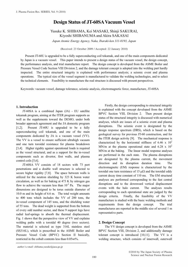
JT-60SA VV consists of 18 sectors with 73 port penetrations and a double wall structure is selected to secure higher rigidity [7,8]. The space between walls is utilized for the neutron shielding by 323 K boron water circulation, as well as for baking at 473 K by nitrogen gas flow to achieve the vacuum less than 10-5 Pa. The major dimensions are designed to be torus outside diameter of 10.0 m and its height of 6.6 m. The total weight amounts to 400 tons which includes the VV of 200 tons, the in-vessel component of 145 tons, and the shielding water of 55 tons. The dead weight is supported from the bottom of every odd number sector, and these 9 support legs have radial leaf-springs to absorb the thermal displacement. Fig. 1 shows that the perspective view of VV and explains welding paths with a toroidal 40 degree (two sectors). The material is selected as type 316L stainless steel (SS316L), which is prescribed in the ASME Boiler and Pressure Vessel Code (BPVC) Section II basically, restricted in the cobalt contents less than 0.05wt%.
Firstly, the design corresponding to structural integrity is explained with the concept developed from the ASME BPVC Section VIII, Division 2. Then present design status of the structural integrity is discussed with numerical analyses, which are issues of a seismic event and plasma disruptions. The seismic event is designated by the design response spectrum (DRS), which is based on the geological survey for previous JT-60 construction, and for the ITER design activity [9]. The mechanical response is characterized by the horizontal stiffness of 6.46 x 10² MN/m at the plasma operational state and 6.28 x 10² MN/m at the baking. The linear modal response analyses are performed in the each state. The plasma disruptions are designated by the plasma current, the movement direction and its disruption duration time. The electromagnetic (EM) response is characterized by the toroidal one turn resistance of 15 μΩ and the toroidal eddy current decay time constant of 110 ms. The EM structural analyses are performed corresponding to the fast central disruptions and to the downward vertical displacement events with the halo current. The analyses results corresponding to each operational state are judged by the design criteria. Finally, the feasibility of the VV manufacture is studied with the basic welding methods and requirements from the design concept. The trial manufactures are reported in the middle size of several 1 m representative parts.
2. Design Concept The VV design concept is developed from the ASME
BPVC Section VIII, Division 2, and additionally damage tolerant concept is introduced [10,11]. The VV is a welding structure, which consists of innerwall, outerwall
180
J. Plasma Fusion Res. SERIES, Vol. 9 (2010)
©2010 by The Japan Society of PlasmaScience and Nuclear Fusion Research
(Received: 23 October 2009 / Accepted: 22 January 2010)
and poloidal rib reinforcement, and it is inevitable to adopt the partial welding method because of the double wall structural characters. The one aspect is closure welding requirement. The closure welding defined in the outerwall structure is one of the difficult parts to apply nondestructive inspection (NDI) whatever ultrasonic test (UT) or radiographic test (RT). Those are treated as a partial penetration welding unless its penetration bead is verified. Consequently, those are required to define an unweld length. The other is the NDI for the on-site welding. UT is not effective to verify a defect size in austenitic weldment, and extensive RT is unrealistic. Consequently, these parts are treated as a partial penetration, and conservative unweld lengths are defined. Another aspect is the consistency with rationalization of manufacturing methods and reduction of welding deformation. The limitation of the welding heat input is desired for especially welded thin walls. The walls are the pressure tight because of shielding water filled between them, however the poloidal rib reinforcement is not. The welding of the ribs is not required to be fully penetration, and partial penetration welding is effective and indispensable to limit the welding region.
The loads on the VV consist of the EM force during the plasma operation and the 0.4 MPa pressure fluctuation of shielding water. The EM force is an uneven load in the poloidal as well as the toroidal, and considered not to cause
the catastrophic fracture as assumed in the general pressure vessels. The VV material of SS316L is well-known for its ductility and toughness, and the walls as the pressure boundary are enough thin of 18 mm so that the final failure mode is anticipated to be the shielding water leakage by plastic collapse or through crack. Although the pressure vessel is designed by the stress criteria which require being defect-free in the pressure tight member, the VV is not such a pressure vessel. The VV is designed by the stress intensity factor criteria which require being damage tolerant in service even though the defect existence is assumed. A conservative defect is defined in the weld joints where the relevant NDI cannot be applied, and the specific life is evaluated by fracture mechanics. This design usually demands the in-service inspection (ISI) but the ISI is difficult because of the VV structural characters. Hence, the sizing criteria of a defect are sophisticated thorough the trial manufactures with each corresponding welding procedure.
The support structure forms the entire structural integrity, and is desired to be compatible with plasma diagnostics ports as well as to avoid the interference with the surrounding facilities even in the seismic events. The support is required to be higher stiffness in the horizontal, but to be lower stiffness in the radial to absorb the thermal displacement during the baking state. As shown in Fig. 1, the support structure is designed at the
Fig.1 JT-60SA Vacuum Vessel and the gravity support (left), 40 toroidal degree (two sectors) of the inboard (middle) and the outboard with port bores (right) are exhibited with various types of weldments. The region circled in the outboard is the R1420 corresponding to the medium size test manufacture.
OutboardInboard
Leaf-spring
Stem
181
Y.K. Shibama et al., Design Status of JT-60SA Vacuum Vessel
every other sector, and consists of radial leaf-spring and stem. Although the toroidal stiffness of a support leg is dominant to determine the horizontal stiffness, the toroidal deflection of the stem is desired to reduce the shear stress in the leaf-spring as well as the out-of-plane deformation of the VV around the stem joint. Consequently, the balance between the horizontal displacement and the induced stress is required to be consistent with the entire structural integrity. The buckling strength as the failure mode is also considered at the weakest leaf-spring, which leads to the different material selection, precipitation hardened stainless steel 660.
3. Performance Analysis The structural integrity is explained with performance
analysis during an in-service period. The double wall VV is a difficult structure to define the evaluation section corresponding to the primary membrane stress and the bending, and the design process through the numerical analysis is required as prescribed in the ASME BPVC Section VIII Division 2. The mechanical behaviour is discussed with the analyses results of a seismic event and EM forces during the plasma operation.
The DRS envelops the natural frequency of the VV, and the dynamic analysis is indispensable to secure the maximum mechanical response. The EM force is
assumed to be a much faster phenomenon than the natural frequency, and the impulsive behaviour is dominant so that the maximum mechanical response is clarified by static analysis.
In each analysis, the reference state is defined corresponding to the operational conditions. The reference state is explained with the temperature dependence of the material properties and pre-loads, such as dead weight, bolt pre-tension and thermal displacement. The least pre-tension load of each bolt is pre-calculated for the conservative analysis. Apparently, the realistic pre-tension is determined with the relevant analyses interpretation and the bolt mechanical properties. The design internal pressure in the double wall is defined as the uniform 0.4 MPa.
3.1 Seismic Analysis In the tokamak devices, the VV is classified to be a
welding structure of 2.0% damping coefficients [12]. The horizontal motion in the seismic event is analyzed with the DRS, characterized with 0.81 G from 3.3 Hz to 7.0 Hz. The vertical component is linearly scaled down from the horizontal spectra with a factor 0.67.
The dynamic response is analyzed by the response spectrum analysis with a modal superposition method of the square root of the sum of the squared values (SRSS method). The modes extraction is determined to satisfy
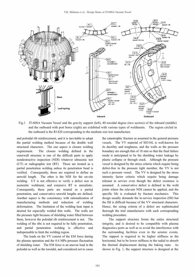
Fig.2 Response spectrum analysis of the seismic event. Maximum displacement responses and dynamic characters of the VV corresponding to each state (left), and element stress plot at the joint between the stem and the VV bottom (right). DRS is input in the weakest direction; 34.8 deg., as explained by the lowest natural frequency.
Mises [Pa](σm + σb )
x34.8 deg
250-deg 290-deg
330-deg
330-degx
z
x
z
yDisp. [m]Scale Factor 200
x
z
x
z
Frequency Stiffness Damping
Vessel bolt & key E. Insu. [Hz] [kN/m] [kN s/m]
Amb. 192 203 28 6.424 651.8 645.9Bake 178 191 28 6.249 616.7 628.2
Horizontal charactersYoung’s Moduli[GPa]
Max. Element Stressσm = 172MPaσm + σb = 235MPa
182
Y.K. Shibama et al., Design Status of JT-60SA Vacuum Vessel
over 95% of total effective mass in the horizontal. The total weight is adjusted to be 400 tons by the density of the outerwall. The contact conditions of flange joint, mechanical key, and electrical insulations are modelled by the spring stiffness element. The lowest natural frequency and its corresponding mechanical characters are summarized in both operational states. The mode characteristics are very similar to each other state, and slightly softer during the baking operation because of the material properties degradation and of the thermal displacement of the leaf-spring. The mechanical response is characterized by the horizontal stiffness of 6.46 x 10² MN/m at the plasma operational state and 6.28 x 10² MN/m at the baking. Here focus on the state during the plasma operation. The lowest natural frequency is resulted in the 6.49 Hz, and the motion is horizontal along with the almost middle of two legs. The sixth mode is resulted in the vertical motion of 21.71 Hz. The horizontal spectrum is input in the weakest direction, as explained by the lowest natural frequency.
The maximum vessel displacement in the horizontal is less than 5.8 mm, and in the vertical is less than 1.0 mm as shown in Fig. 2. The displacement criteria, of 9.0 mm in the horizontal and of 3.0 mm in the vertical, are satisfied. The acceleration of 9.6 m/s2 is induced on the top of the vessel surface, but higher acceleration is induced at the port edge and penetration pipe. The surrounding apparatus design is required to be compatible with each acceleration condition. The most of induced stresses are
with in the design limit, but the stresses at the both ends of the stem are locally peaked over 200 MPa. Those stresses however are within the capacity of reinforcements or the fatigue design. Stresses in the key, the bolt and its groove in the flange are within the material selection as well as the fatigue design.
Although the response during the baking operation is similar but explained with the thermal displacement, the analysis result is in the same trend and confirmed within the design limits as well as the peak stress treatment. The motion is characterized by the horizontal of 6.25 Hz and vertical of 20.86 Hz. The vessel displacements are slightly higher, horizontal 6.5 mm and vertical 1.5 mm, but also satisfy the displacement criteria.
In the real structure, the natural frequency is anticipated to be lower because of discrepancies due to the numerical modelling, such as mechanical joints, and the contact behaviour. The lower natural frequency leads to the more displacement but the less stress, and experimental assessments are desired to validate the stiffness in each direction.
3.2 Electromagnetic Analysis
Plasma Major Disruption (MD) is a phenomenon that rapid dissipation of its current and thermal energy is caused by confinement loss and impurity influx, and the current quench duration is dependent on the asymmetric coupling with the passive conducting structure. The shorter
Mises [Pa](σm + σb )
Max. Element Stressσm = 142MPaσm + σb = 224MPa
Scale Factor 200
Radial Toroidal Z[kN] [kN] [kN]
Eddy P-14 -731 -0.4 12Eddy P-15 -729 2.3 27Eddy P-14 -838 0.6 -48Eddy P-15 -806 4.6 -20Eddy P-14 -569 -4.3 -8.5Eddy P-15 -533 -1.3 16Eddy P-14 -732 3.4 -161Eddy P-15 -688 6.1 -141Eddy -1144 -210 9.3 Max. of Halo CurrentHalo -173 -22 -93 IHalo x TPF = 1.01 [MA] (DINA)
Eddy -1070 -192 60 Max. of Halo CurrentHalo -176 8.0 -94 IHalo x TPF = 1.01 [MA] (DINA)
Eddy P-14 -539 -4.5 24Eddy P-15 -473 -2.3 52Eddy P-14 -645 4.0 -263Eddy P-15 -591 6.0 -248Eddy -985 -178 -100 Max. of Halo CurrentHalo -211 -37 -167 IHalo x TPF = 1.36 [MA] (DINA)
Eddy -870 -153 -48 Max. of Halo CurrentHalo -214 -37 -168 IHalo x TPF = 1.36 [MA] (DINA)
Eddy -985 -178 -100Halo -682 1.3 -529 IHalo x TPF = 0.5 x IP = 2.75 [MA]
Eddy -870 -153 -48Halo -689 1.2 -534 IHalo x TPF = 0.5 x IP = 2.75 [MA]
Eddy P-14 -638 -115 -19Eddy P-15 -639 -116 -21
VDE-2_01
VDE-2_02
MD_01
MD_02
VDE-1_01
VDE-1_02
CurrentCategory
Total EMFRemarks
TF-FD
VDE-1_H
VDE-2_H-02
P-14
ID
P-15
P-14
P-15
Sector
VDE-2_H-01P-14
P-15
Max. Load on Baffle
Max. Load on Vessel
TF Magnet Fast Discharge(τ = 9.0 [s])
Max. Load on Baffle
Max. Load on Vessel
Max. Load on Baffle
Max. Load on Vessel
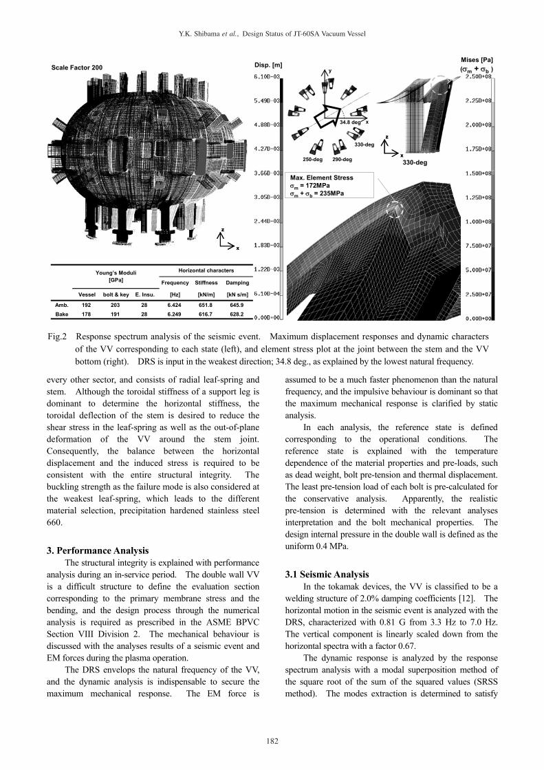
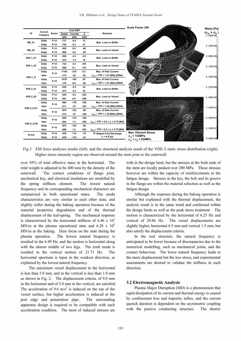
Fig.3 EM force analyses results (left), and the structural analysis result of the VDE-2 static stress distribution (right). Higher stress intensity region are observed around the stem joint to the outerwall.
183
Y.K. Shibama et al., Design Status of JT-60SA Vacuum Vessel
duration results in higher loads on the in-vessel components as well as the centripetal load on the VV, and the shortest duration of 4 ms is assumed in the design.
Vertical Displacement Event (VDE) is a failure event due to the stability loss of the plasma vertical position. The plasma motion will evolve into the upward drift or the downward without plasma current reduction, and higher EM force is induced when the duration from the beginning to the current quench is longer. The halo current flows into the structure, and passes the lower impedance circuit with the halo region. The extreme current paths are assumed that the halo currents are intercepted by the diverter cassette edge and flow in the double wall. The force is primarily vertical, and the downward is combined with the dead weight. Two cases of VDE are assumed; a case of 10 ms (VDE-1) and the slower of 30 ms (VDE-2). The VDE-2 is characterized by higher halo currents, and the maximum design asymmetry is considered by a toroidal peaking factor.
The transient plasma behaviour is analyzed by the two dimensional plasma disruption code DINA [13,14]. The transient plasma models are converted to the three dimensional transient eddy current code EDDYCAL, and treated by two analyses process; the transient eddy current and the halo current [15,16]. The EM forces calculated separately are interpreted into the structural analysis code ABAQUS, and superimposed corresponding each disruptive event.
The two of EDDYCAL models are prepared; the simple one for the EM force time evolution and the other detailed for the time sliced. The simple model is a 20 degree model consisted of the VV, the baffle and the
in-vessel vertical control coils. The detail model is a 40 degree model consistent with the structural model coordinates. The typical sectors are selected; P-14 (outboard three diagnostics port penetrations) and P-15 (a large port bore). The detailed includes the VV with the ports bore, the baffle and the in-vessel vertical control coils. The SS316L resistivity is 0.739 μΩ/m at 293 K, and EM characters of the toroidal one turn are decay time constant of 110 ms as well as resistance of 15 μΩ. The EM response of the VV is inductive during the plasma disruption, and resistive during the TF magnet fast current discharge event.
In the plasma operation, the inductive response of the passive structures causes magnetic shielding effects on each other structure, and the time rag of the EM force peak is observed between the baffle and the vessel. The toroidal eddy current results in the centripetal force of over 0.8 MN/sector, and halo current results in the vertical force of over 0.5 MN/sector as summarized in Fig. 3. The analyses results indicate that two structural analyses corresponding to each EM force peak are required for the entire VV analyses and the baffle.
Three dimensional structural model is 40 degree (2 sectors) axial symmetry, and the dead weight of the model is adjusted to be total 400 tons total by the density of the outerwall. The integrity of the vessel and its support are focused, and explained along with the VDE-2 of the higher halo current as shown in Fig. 3. The dominant vertical force resulted in the over 2 mm in the downward displacement. The higher stress is induced in the vessel and its support joint, however key and its groove in the flange as well as bolts receive little operational EM load.
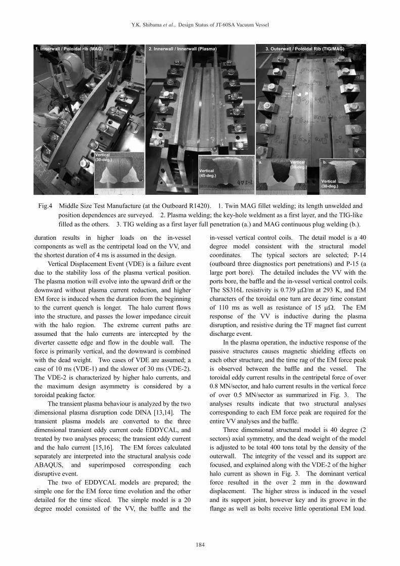
Fig.4 Middle Size Test Manufacture (at the Outboard R1420). 1. Twin MAG fillet welding; its length unwelded and position dependences are surveyed. 2. Plasma welding; the key-hole weldment as a first layer, and the TIG-like filled as the others. 3. TIG welding as a first layer full penetration (a.) and MAG continuous plug welding (b.).
Vertical(30-deg.) Vertical
(30-deg.)
Vertical(30-deg.)
Vertical(45-deg.)
1. Innerwall / Poloidal rib (MAG) 2. Innerwall / Innerwall (Plasma) 3. Outerwall / Poloidal Rib (TIG/MAG)
a. b.
184
Y.K. Shibama et al., Design Status of JT-60SA Vacuum Vessel
The stresses induced in the VV are within the design limit except for the joint between the vessel and the stem, however those stresses are limited and within the peak stress treatment.
4. Manufacture and its trial The basic flow of the VV manufacture is that a
toroidal 40 degree (2 sectors) unit is manufactured in the workshop, and these units split are united in the on-site. Each sector unit is split in several small segments, and the manufacturing process is based on the assembly of these segments. A segment manufacture is that the poloidal rib is jointed to the innerwall, and then the outerwall is jointed on the rib-innerwall segments. These segments are prepared each other and enlarged by joints in the poloidal.
The test manufactures are the process to validate the welding technologies as well as to select the technical elements, and consist of major two; the 1 m middle size test manufacture and the toroidal 20 degree upper unit. Here focus on the middle size test manufacture; the outboard part (R1420) under the status quo.
Several 1 m middle size test manufacture are already accomplished to validate the welding conditions, to study the deformation reduction by the block sequence combined with intermittent weld, to design the constraint jig, and to recover the angular distortion. An example result is shown in Fig. 4; the outboard part (R1420), and the process is explained along with this typical case.
Firstly, the innerwall and rib are fillet-welded with the twin MAG. The length unwelded and position dependences are surveyed to achieve uniform penetration because of the lack of the sizing accuracy of the UT. The angular distortion is also confirmed to be recoverable. Then, the segments manufactured are butt-welded by the plasma full penetration. The first layer is key-holed, and other layer is welded with filler wire to achieve the TIG-like deposited metal.
The outerwall are welded on the poloidal rib by TIG full penetration as a first layer, and the other layers are welded by the MAG continuous plug welding. The rib and outerwall are closure-welding, and the full penetration requires confirming the penetration bead. The confirmation spawns the difficulty and its cost, and the welding processes are studied to achieve full penetration independent of the position.
Several other segments are also confirmed to validate their weldability along with its actual position and methods applicability.
5. Conclusions The design status of the VV is explained with the
design concept, performance analysis and trial manufacture.
The design concept is based on the ASME Section
VII Division 2, fully assessed by the numerical analyses because of the double wall structural character. Additionally, the damage tolerant concept is introduced where NDI are hardly applicable, and fracture mechanical analyses to assess the residual strength as well as to assure the damage tolerance are required corresponding to each weldability.
The entire VV mechanical response during the normal operations is explained by the performance analysis; a seismic event and plasma operations. Those mechanical response characters are classified by their load spectrum and the VV natural frequency. The analyses results provide of good design perspectives and are desired to indicate a consistency with the detailed welding classification to be rationalized manufacture process.
The 1m middle size of the vessel segments is manufactured to validate the welding technologies, and to select the technical elements. The more trial manufacture is required such a larger size to validating the dimensional accuracy of the real size, constraint jig, weldability of the on-site.
These results are reorganized to assure its consistency of the design concept with manufacture process. [1] T.Fujita et al., Nuclear Fusion 47, 1512 (2007). [2] S.Ishida et al., Fusion Eng. Des., Submitted. [3] M.Onozuka et al., Fusion Eng. Des. 55, 397 (2001). [4] H.Horiike et al., Fusion Eng. Des. 16, 285 (1991). [5] N.Hosogane et al., Fusion Science Technology 42, 368
(2002). [6] S.Sakurai et al., Fusion Eng. Des. 39-40, 371 (1998). [7] M.Nakahira et al., Nuclear Fusion 41, 375 (2001). [8] K.Ioki et al., Fusion Technology (Elsevier Science
Publishers B.V., 1989) p. 764. [9] S.Tado et al., Seismic, Shock, and Vibration Isolation
-1998, ASME 1998 PVP-Vol.379, 197 (1998). [10] D.Broek: Elementary Engineering Fracture Mechanics
fourth revised edition, Kluwer Academic Publishers (1986).
[11] R.A.Ainsworth, Engineering Fracture Mechanics Vol.19, No.4, 633 (1984).
[12] U.S.NRC, Recommendations for Revision of Seismic Damping Values in Regulatory Guide 1.61, NUREG/CR-6919, (2006).
[13] M.Sugihara, et al., Nuclear Fusion 47, 337 (2007). [14] Vctor Lukash et al., Plasma Phys. Control. Fusion 47,
2077 (2005). [15] A.Kameari, Journal of Computational Physics Vol.42,
No.1, 124 (1981). [16] S.Niikura and A.Kameari, International Journal of
Applied Electromagnetics in Materials, Vol.3, 29 (1992).
185
Y.K. Shibama et al., Design Status of JT-60SA Vacuum Vessel


![Pressure Vessel [Design]](https://img.pdfslide.tips/doc/110x75/546b26fcb4af9f000e8b4629/pressure-vessel-design-5584556ceffe5.jpg)