Embed Size (px)
Citation preview

Development of Network Operation Knowledge System
Takashi Shimizu, Takao Oono, Masanori Furutani, Katsuyuki Tsumita, Makoto Jinguji
Network System Development DepartmentResearch and Development Division NTT DoCoMo, Inc.3-5 Hikarinooka, Yokosuka, Kanagawa, 239-8536 Japane-mail:[email protected]
AbstractIn order for the efficiency of operation and fast error recovery, a syste
m that can manage a network comprehensively by managing and analyzing error messages output from elements within the network in an integrated fashion, and decide and execute the error recovery automatically is promising. To realize the targets described above, the authors proposed a networkoperation knowledge system and confirmed that we can apply it to commercial business environment.This paper explains the outline of the knowledge system and its technical characteristics. It also explains, with an example, how existing operations can be improved by introducing the system.
247

2
1. Introduction
▌ Current Maintenance Method: Centralized maintenance in one location▌ Takes a long time to understand the situation when multiple
OSSs output error messages caused by the same error.▌ Depending on the skill level of maintenance personnel, there are
cases where it may take a long time for error isolation and maynot be able to make an appropriate judgment
▌ Development of a network operation knowledge system which aims at “ Efficient Operation “ and “Reduction of Error Handling Time “
1. IntroductionCurrently, control terminals for Operation Support System (OSS:Operation Support System)for network elements(NE:Network Element), which form a mobile communication network, are centralized in one location, thereby providing network-wide maintenance of a mobile communication network through establishing an operating environment that monitors and controls the network comprehensively. Inter-OSS coordination in such centralized maintenance assumes maintenance personnel's intervention. Therefore, for example, if error messages are output from the node system OSS and access system OSS for the same error, it takes a long time to understand the situation, and in some cases this results in delay in the initial investigation such as error isolation. There are also cases where due to the insufficient skill-level of error handling maintenance personnel, it takes a long time for error isolation and appropriate judgment is not possible. As a communication carrier, when errors occur which impact customers, such as communication being disabled, it is essential that very quick error recovery is perfumed.Based on the background described above, aiming at “ efficient operation “ and ” reduced error handling time”, a network operation knowledge system (knowledge system, hereafter )was proposed and we can apply it to commercial business environment.[1]~[3].This paper explains the outline of the knowledge system and its technical characteristics. It also explains, with an example, how existing operations can be improved by introducing the system.
248
3
2. System Overview
NE : Network ElementNE OSS : NE Operation Support SystemNC OSS : Network Control Operation Support System
NEBS
SW transmission SWBS
NE OSS NC OSS
Network Operation Knowledge System
OSS OSSOSS OSS
RNC RNC
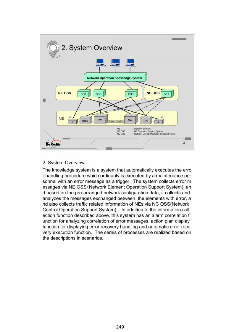
2. System OverviewThe knowledge system is a system that automatically executes the error handling procedure which ordinarily is executed by a maintenance personnel with an error message as a trigger. The system collects error messages via NE OSS(Network Element Operation Support System), and based on the pre-arranged network configuration data, it collects and analyzes the messages exchanged between the elements with error, and also collects traffic related information of NEs via NC OSS(NetworkControl Operation Support System) . In addition to the information collection function described above, this system has an alarm correlation function for analyzing correlation of error messages, action plan display function for displaying error recovery handling and automatic error recovery execution function. The series of processes are realized based on the descriptions in scenarios.
249

4
3.1 Multi-Module Configuration
NE OSS
Network Operation Knowledge System
OSSadapter
Data Management Server
Web Server
Automatic Execution Server
Node SystemNE OSS
Access SystemNE OSS
Link SystemNE OSS
NodeSystemAdapter
AccessSystemAdapter
LinkSystemAdapter
NC OSS
TrafficSystemAdapter
Traffic SystemNC OSS
OPE
3. Characteristics of the System 3.1. Multi-Module ConfigurationWhen new services are provided, there are cases where NEs, such as servers, are added. Also, for performance improvement of a system or integration, existing NEs may be replaced by new NEs. When new communication system is introduced, such as when FOMA(Freedom Of Mobile multimedia Access)service was started, a large number of various NEs tend to be introduced simultaneously.Since the knowledge system is targeted to be a system that executes and controls the error handling network-wide, it is necessary to have an architecture flexible enough to expand for adding new NEs and changing NEs as described above.For this purpose, this system adopts a multi-module system configuration that enables functional distribution and load distribution based on the changes in the types and numbers of error messages. The following slides explain the roles and characteristics of main modules in this system.
250

5
3.1 Multi-Module Configuration
NE OSS
Network Operation Knowledge System
OSSadapter
Data Management Server
Web Server
Automatic Execution Server
Node SystemNE OSS
Access System NE OSS
Link SystemNE OSS
NodeSystemAdapter
AccessSystemAdapter
LinkSystemAdapter
NC-OSS
TrafficSystemAdapter
Traffic SystemNC OSS
OPE
(1)OSS Adapter OSS adapter is a module that converts communication interface between each OSS and the knowledge system. The OSS adapter takes care of the interface conversion with each OSS in order to prevent development of new functions on the OSS side for the purpose of developing the knowledge system. This interface conversion function is concentrated in a module called OSS adapter, and the architecture is configured so that the OSS adapter can take care of the interfaces with each OSS as much as possible.
(2)Data Management ServerData management server manages error messages, error handling scenarios and their execution results, and various data including network configuration data.Error messages are output from NEs when errors occur. The messages are transferred to the automatic execution server via OSS adapter, then stored in the data management server. The error messages stored are used for display for maintenance personnel, error isolation and error handling decisions.Network configuration data is information on network configuration, such as inter-NE connection and inter-OSS connection. The configuration data is used to make a judgment on correlation of error messages, etc. For example, when an error occurs in the interface part of an element , there are cases where both the interface in error and NE connected with the interface notify the error in the line. In such a situation, it is possible to perform correlation by identifying connected elements through searching the configuration data based on information included in the error messages notified from each element . The error handling scenario is a description of an error handling procedure. The scenario is used in the automatic execution server to correlate error messages, collect related information and execute error recovery. The error handling scenario can be replaced without file updates.
251
6
3.1 Multi-Module Configuration
NE OSS
Network Operation Knowledge System
OSSadapter
Data Management Server
Web Server
Automatic Execution Server
Node SystemNE OSS
Access System NE OSS
Link SystemNE OSS
NodeSystemAdapter
AccessSystemAdapter
LinkSystemAdapter
NC OSS
TrafficSystemAdapter
Traffic SystemNC OSS
OPE
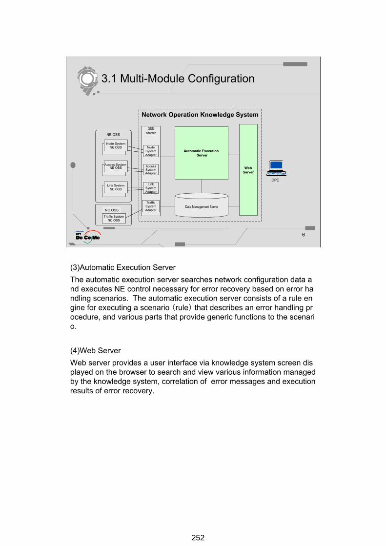
(3)Automatic Execution ServerThe automatic execution server searches network configuration data and executes NE control necessary for error recovery based on error handling scenarios. The automatic execution server consists of a rule engine for executing a scenario (rule) that describes an error handling procedure, and various parts that provide generic functions to the scenario.
(4)Web ServerWeb server provides a user interface via knowledge system screen displayed on the browser to search and view various information managed by the knowledge system, correlation of error messages and execution results of error recovery.
252
7
3.2 Hierarchical Software StructureEmploying Scenario
Network Operation Knowledge System
OSSAdapter
Data Management Server
Web server
Automatic Execution Server
NE OSS
OPE
API Part
Rule Engine
ScenarioError Message
Confirm Status
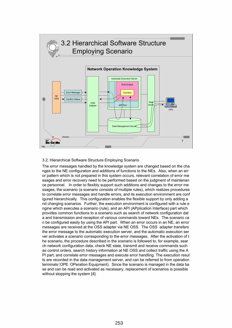
3.2. Hierarchical Software Structure Employing Scenario The error messages handled by the knowledge system are changed based on the changes to the NE configuration and additions of functions to the NEs. Also, when an error pattern which is not prepared in this system occurs, relevant correlation of error messages and error recovery need to be performed based on the judgment of maintenance personnel. In order to flexibly support such additions and changes to the error messages, the scenario (a scenario consists of multiple rules), which realizes procedures to correlate error messages and handle errors, and its execution environment are configured hierarchically. This configuration enables the flexible support by only adding and changing scenarios. Further, the execution environment is configured with a rule engine which executes a scenario (rule), and an API (APplication Interface) part which provides common functions to a scenario such as search of network configuration data and transmission and reception of various commands toward NEs. The scenario can be configured easily by using the API part. When an error occurs in an NE, an error messages are received at the OSS adapter via NE OSS. The OSS adapter transfers the error message to the automatic execution server, and the automatic execution server activates a scenario corresponding to the error messages. After the activation of the scenario, the procedure described in the scenario is followed to, for example, search network configuration data, check NE state, transmit and receive commands such as control orders, search history information at NE OSS and collect traffic using the API part, and correlate error messages and execute error handling. The execution results are recorded in the data management server, and can be referred to from operation terminals(OPE:OPeration Equipment). Since the scenario is managed in the data base and can be read and activated as necessary, replacement of scenarios is possible without stopping the system [4].
253

8
3.3 How to Realize Error MessageCorrelation
OSS
Self disappearance
Eventreception
unit
Event cache
Error A message … …Error B message … …
Correlation startsCorrelation A response
(1) Searches event cache(2) Obtain related error B info(3) Judges error A to be main cause(4) Starts measure execution
Measure executionOSS
OSS
OSS
OSS
OSS
OSS Adapter
Error A (Main cause)message
Error B (Related)message
Correlation starts Correlation B response
(1) Searches event cache(2) Obtain related error A info(3) Judges error A to be main cause(4) Correlation ends
3.3. How to Realize Error Message Correlation The existing coordination between the OSSs assumes an intervention of maintenance personnel. Therefore, when an error that is related to NE types occurs and error messages are issued caused by the same error between the node system OSS and access system adapter OSS, it takes a long time to understand the state of the network operation, and as a result, initial recovery handing delays.To reduce this delay in the initial recovery handling, it is important to select and notify the maintenance personnel the real cause of the error, the error message and other related error messages notified, after clarifying the correlation among multiple error messages detected and notified due to the same error regardless of NEs. To realize this, a correlation techniques [2],[5]~[6] are necessary to analyze and integrate the correlation of notified error messages.The scheme to correlate error messages in the knowledge system is a autonomous distributed correlation scheme in that after activating an error handling scenario corresponding to each error message, related error messages are autonomously searched based on the description in each scenario and correlation with the error message which matches the erroneous behavior is drawn. Details are explained as follows:Let us suppose that an error occurs in an NE and an error message A (main cause message) to notify the real cause of the error, and an error message B (related message), which is caused by the error, are issued. The OSS adapter receives the error message A and error message B, and notify them to the event reception unit of the automatic execution server. The event reception unit stores each error message in a memory area, called event cashe, for managing error messages being issued, then activates the error handling scenario for the error message A and B independently. Each error handling scenario activated searches the event cashe based on the description in the scenario, collects error message information corresponding to the correlation, and analyzes if the error message is for the main cause. As a result of the analysis, the error handling scenario for the error message A judges that the error message A is the message for the main cause and error message B is a related message, and its own scenario corresponds to the main cause, and registers the result of main cause identification in the data management server. On the other hand, the error handling scenario for the error message B analyzes that the error message A is for main cause and error message B is a related error message, and its own scenario corresponds to the related message. When the judgment is drawn, the scenario is eliminated by itself. Through this process, only the scenario corresponding to the main cause remains, and as a result, correlation is established.This autonomous distributed correlation scheme can activate an error handling scenario per error message, therefore, it eliminates the need for scenario descriptions (work) according to the order of reception of all the related messages, which enables writing the error handling scenario per error message. This enhances the independence of scenarios and facilitate scenario description at the same time.
254

9
3.4 Mechanism for Configuration DataManagement
Data Management Server
Existing OSS Hierarchical Data Base
Data Related to X Data Related to Y
Data Related to Z
Network HierarchicalData Base
Data Related to α①
②
③⇒④
① ② ③⇒④
Synchronously updated when existing OSS hierarchical data have been changed
3.4. Mechanism for Configuration Data Management To correlate error messages, it is necessary to identify elements, such as other NEs, connected to the error element based on the information included in the error messages. To perform this, network configuration data is necessary to manage the inter-NE relations, or inter- element relations within an NE, for enabling the search of connected elements by using information included in the error messages as a key. However, the volume of network configuration data is enormous and it is required that the latest data is always available. In the knowledge system, the challenge described above is solved by using the information available to the existing NE OSS and the minimum additional mechanism.
(1)Hierarchy of Network Configuration Data In the existing NE OSS, there is a configuration information management system which commonly manages information necessary for each OSS. Each OSS downloads and uses information such as inter- element connection information within an NE from the configuration information management system. The existing NE OSS is configured per category unit namely node, access and link, and each OSS does not require information from other category. Therefore, the configuration information management system also manages information per NE type, such as node, access link as is the case for OSS, and the structure does not allow the integrated management of the entire network. To solve this issue, in the knowledge system, data management is performed in 2 layers, namely existing OSS layer and a layer for the network as a whole. The existing OSS layer data can be downloaded from the configuration information management system by using the existing NE OSS scheme. Data in the network layer is structured as new data necessary for correlation based on the data in the existing OSS layer. Fast search of optimum data necessary for correlation is realized by creating data in the network layer. (2)Update of Network Configuration InformationData in the existing OSS layer is updated using the update function equipped in the configuration information management system. It is structured in such a way that data in the network layer is to be structured based on data in the existing OSS layer, and synchronously updated when data in the existing OSS layer is updated. Thereby, high accuracy correlation is always possible based on the latest network configuration data.
255
10
3.5 Coordination with Other ElementManagement Systems
Network Operation Knowledge System
Data Management Server
Automatic Execution Server
API Part
Rule Engine
Scenario
Data of NE with Work in Progress
Element Management System
Data of NE with Work in Progress
Notify Status of NE withWork in Progress
Stop execution if work in progress
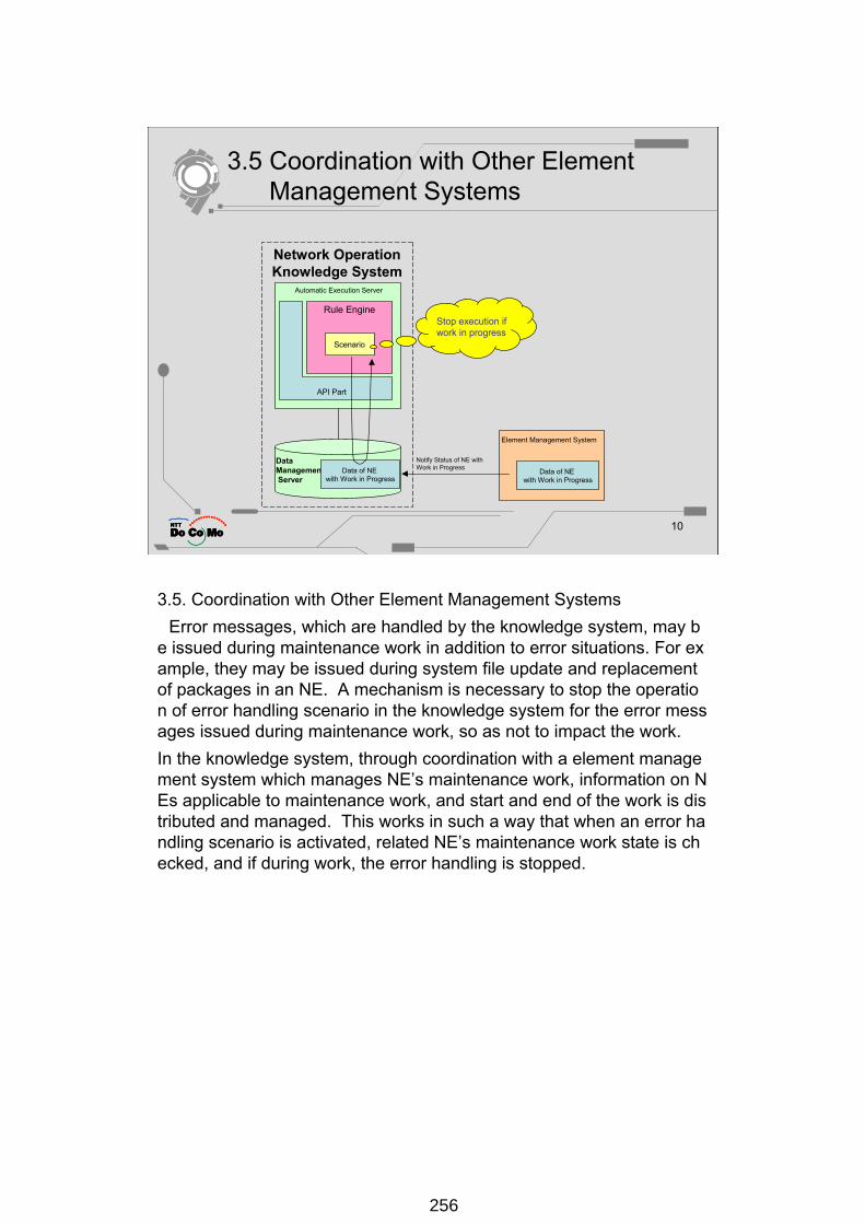
3.5. Coordination with Other Element Management Systems Error messages, which are handled by the knowledge system, may be issued during maintenance work in addition to error situations. For example, they may be issued during system file update and replacement of packages in an NE. A mechanism is necessary to stop the operation of error handling scenario in the knowledge system for the error messages issued during maintenance work, so as not to impact the work.In the knowledge system, through coordination with a element management system which manages NE’s maintenance work, information on NEs applicable to maintenance work, and start and end of the work is distributed and managed. This works in such a way that when an error handling scenario is activated, related NE’s maintenance work state is checked, and if during work, the error handling is stopped.
256
11
4 .Example of Error Handling OperationEmploying Knowledge System
【Current】
MLSBCEMDEPDCPDC AccessAccess
In charge of PDC access
①TRX Card ALM
Periodic Testing, Search MN Journal
Need to confirm MN alarm issuance
MLSBCEMDEPDCPDC AccessAccess
In charge of PDC access In charge of PDC node
③MLS Error
・ Recover・Issue Trouble Ticket
OK
NGNormality Check OK? ⇒ Stop Alarm ⇒OCT・ICT Test
Inquire at Personnel in charge of PDCNode
In Case of Access System Element In Case of Access System Element ErrorError
In Case of Node System In Case of Node System Element ErrorElement Error
・Issue Trouble Ticket ・Arrange for Error Handling
・ Recover・Issue Trouble Ticket
OK NG
担当間で連携が必要
MJMJMNMN
Confirm Event and Work Information
②ALM for Low Completion Rate Call Origination
TRX Card Reset
Confirm CH Utilization
Confirm through OCT Test
Confirm Call Processing Alarm
Confirm Event and Work Information
②ALM for Low Completion Rate Call Origination
TRX Card Reset
Confirm CH Utilization
Confirm through OCT Test
Confirm Call Processing Alarm
違う原因で同じアラームがでるため、アラームのみで原因を特定できない
作業中であるか工事計画部門に確認が必要(要電話対応)
Coordination is necessary between personnel in charge
Causes of errors cannot be identified only by the alarm, because the same alarm is issued for different causes
Need to check with work planning section if work in progress (Telephone communication necessary)
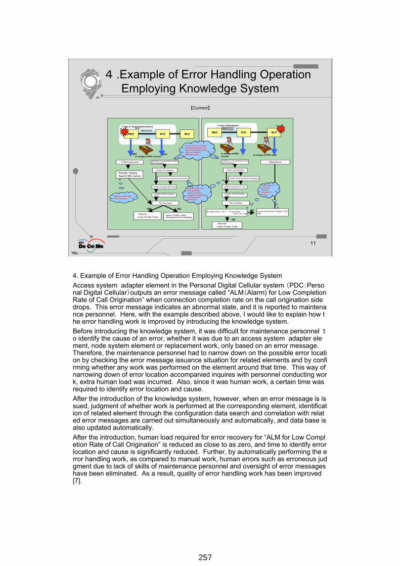
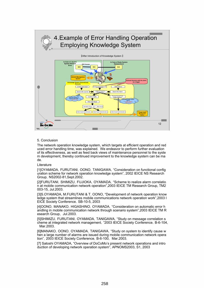
4. Example of Error Handling Operation Employing Knowledge SystemAccess system adapter element in the Personal Digital Cellular system (PDC:Personal Digital Cellular)outputs an error message called “ALM(Alarm) for Low Completion Rate of Call Origination” when connection completion rate on the call origination side drops. This error message indicates an abnormal state, and it is reported to maintenance personnel. Here, with the example described above, I would like to explain how the error handling work is improved by introducing the knowledge system.Before introducing the knowledge system, it was difficult for maintenance personnel to identify the cause of an error, whether it was due to an access system adapter element, node system element or replacement work, only based on an error message.Therefore, the maintenance personnel had to narrow down on the possible error location by checking the error message issuance situation for related elements and by confirming whether any work was performed on the element around that time. This way of narrowing down of error location accompanied inquires with personnel conducting work, extra human load was incurred. Also, since it was human work, a certain time was required to identify error location and cause.After the introduction of the knowledge system, however, when an error message is issued, judgment of whether work is performed at the corresponding element, identification of related element through the configuration data search and correlation with related error messages are carried out simultaneously and automatically, and data base is also updated automatically. After the introduction, human load required for error recovery for “ALM for Low Completion Rate of Call Origination” is reduced as close to as zero, and time to identify error location and cause is significantly reduced. Further, by automatically performing the error handling work, as compared to manual work, human errors such as erroneous judgment due to lack of skills of maintenance personnel and oversight of error messages have been eliminated. As a result, quality of error handling work has been improved [7].
257
12
4.Example of Error Handling OperationEmploying Knowledge System
【After Introduction of Knowledge System 】
MLSBCEMDE
PDCPDC AccessAccessIn Case of Node System In Case of Node System
Element ErrorElement Error
Element Management System
In Case of Access In Case of Access System Element System Element
ErrorError
Knowledge System Automatically Executes
③MLS Error
OK
②ALM for Low Completion Rate of Call Origination①TRX Card ALM
Search MJ Alarm
Automatic Analysis of Collected Information→ Reduced Time
Judgment based on Element Alarm
NG
Collect and Analyze Related Alarms
→ Identify element Causing Error
Node SystemAccess System
Activate Scenario with the alarm Activate Scenario with the alarm as a triggeras a trigger
Trouble Ticket Management
System
Notify Trouble Ticket InformationNotify Trouble Ticket Information Notify Trouble Ticket Information
Process through Node System Scenario
Search MN Journal
Normality Check OK? State Inquiry
TRX Card Reset
Confirm Traffic
5. ConclusionThe network operation knowledge system, which targets at efficient operation and reduced error handling time, was explained. We endeavor to perform further evaluation of its effectiveness, as well as feed back views of maintenance personnel to the system development, thereby continued improvement to the knowledge system can be made.Literature[1]OYAMADA,FURUTANI,OONO,TANIGAWA,“Consideration on functional configuration scheme for network operation knowledge system”, 2002 IEICE NS Research Group,NS2002-81,Sept.2002.[2]FURUTANI,SHIMIZU,FUJIOKA,OYAMADA,“Scheme to realize alarm correlation at mobile communication network operation”,2003 IEICE TM Research Group, TM2003-15, Jul.2003.[3]S.OYAMADA, M.FURUTANI & T. OONO, “Development of network operation knowledge system that streamlines mobile communications network operation work”,2003 IEICE Society Conference,SB-10-5, 2003[4]OONO,MANAKO,HIGASHINO,OYAMADA,“Consideration on automatic error handling in mobile communication network through scenario system”,2003 IEICE TM Research Group, Jul.2003.[5]SHIMIZU,FURUTANI,OYAMADA,TANIGAWA,“Study on message correlation scheme at integrated network management,”2003 IEICE Society Conference,B-6-104, Mar.2003.[6]MANAKO,OONO,OYAMADA,TANIGAWA,“Study on system to identify cause when a large number of alarms are issued during mobile communication network operation”,2003 IEICE Society Conference,B-6-100, Mar.2003.[7] Satoshi OYAMADA, “Overview of DoCoMo’s present network operations and introduction of developing network operation system”, APNOMS2003, S1, 2003
258