Embed Size (px)
Citation preview
Mainstvo 2(4), 75 – 92 (2000) Duhovnik J.,...; DOPRINOS SIMULACIJI PROIZVODNIH...
DOPRINOS SIMULACIJI PROIZVODNIH PROCESA U CAPP
Prof. dr. Jo`e Duhovnik, Janez Vrhovec, dipl.in`., CAD Center-LECAD, Univerza v Ljubljani, Fakulteta za strojnitvo, Ljubljana, Slovenija
REZIME
Procesi u pojedina~noj i maloserijskoj proizvodnji imaju vlastive u fazi osnivanja proizvoda. U ~lanku su obra|ene zakonitfazu proizvoda. Pri analizi zakonitosti upotrebljena je ra~unarsutje~u na proces i praeni rezultati, kao to su protoiskoritenost resursa. Analiziran je uticaj promjenljivih izradndu`ine radne smjene.
D
Klju~ne rije~i: simulacije, pojedina~na proizvodnja, planiranj
CONTRIBUTION TO THE OF PRODUCTION PROCES
Jo`e Duhovnik Ph.D., professor, Janez Vrhovec, Bsof Ljubljana, Faculty of Mechanical Engineering, L SUMMARY
Processes in individual and small-quantity production have printo account during the conceptual design phase of a prodof such processes which affect the product development phthe analysis of these principles. The parameters affecting thsuch as flow times, resource utilization and production capvarying machining times in connection with work shift lengths
Keywords: simulations, individual production, production pla
1. UVOD Uslov za uspjenost poslovnog sistema jeste vremensko savladavanje proizvodnih procesa, sa stajalita trokova kao i kapaciteta. Pored zahtjeva za kvalitetom, pouzdanosti, cjenama i rokovima, pojavljuju se i te`nje za veu iskoritenost kapaciteta i planiranje na du`i rok. Za razliku od serijske proizvodnje, gdje su prilike predvidljive na du`i rok, raspore|ivanje rada u pojedina~noj proizvodnji je potrebno prilagoditi trenutnim uslovima, jer se on kroz du`e vremensko razdoblje mo`e zna~ajno mijenjati. Kod primjera proizvodnje po narud`bi i varijantnog konstruiranja, proizvodi su u velikoj mjeri sli~ni i mogu imati jednake pojedine sastavne dijelove ili razli~iti djelovi imaju sli~an redosljed tehnolokih operacija. Za planiranje i vo|enje takve proizvodnje mogu se upotrebiti metode i tehnike kao i ra~unarski alati, koji su razvijeni za projektno vo|enje.
1. INTR Time maviewpoint essential system. Indelivery tgreater ulonger tcircumstathe distribto be adchange cWhen prthe level and maalternativesequenceplan andand techfor projecomputer
- 75 -
IZVORNI NAU^NI RA
te zakonitosti, koje je potrebno uva`avati osti tih procesa, koje utje~u na razvojnu ka simulacija. Mjenjani su parametri, koji ~na vremena, kapacitet proizvodnje i ih vremena u zavisnosti od vremenske
e proizvodnje, raspore|ivanje rada
SIMULATION SES IN CAPP
C, CAD Center-LECAD, University jubljana, Slovenia
ORIGINAL SCIENTIFIC PAPERinciples which already need to be taken uct. This paper discusses the principles ase. Computer simulation was used for e process were varied and the results acity were observed. The influence of was analyzed.
nning, task scheduling
ODUCTION
nagement of production processes, from the of costs and with respect to capacities, is an condition for the success of a business addition to requirements for quality, reliability, imes and prices, there are also demands for tilization of capacity and planning over a erm. Unlike serial production, in which nces can be predicted over the longer term, ution of work in individual production needs apted to current conditions, since these can onsiderably over a longer period of time. oducts are made to order and designed at of variant design, they show great similarities y have certain identical components, or ly different components may have a similar of technological operations. In order to manage such production, certain methods niques which have already been developed ct management can be used as well as tools.
Mainstvo 2(4), 75 – 92 (2000) Duhovnik J.,...; DOPRINOS SIMULACIJI PROIZVODNIH...
Sa druge strane zna~ajno je poznavati zakonitosti, koje nastupaju kod takvih proizvodnih procesa. Prou~avanje prilika u proizvodnim sistemima, koji su po odre|enim kriterijima veoma sli~ni, mo`e ukazivati na odre|ene zakonitosti, koji ne mogu biti opte primjenljive na sve proizvodne sisteme, ali koje u odre|enem trenutku ~ine zna~ajan oslonac kod odlu~ivanja u okviru vo|enja i planiranja proizvodnje.
It is also important to know the principles which govern such production processes. The study of circumstances in production systems which are very similar in terms of certain criteria reveals the recognized principles, which, however, are not generally transferable to all production systems, but which may at some point prove to be an important support in the decision-making process of production management and planning.
1.1 Zadaci vo|enja proizvodnje Vo|enje proizvodnje je bitan faktor u proizvodnom procesu. Njenova funkcija je donoenje odluka sa ciljem obezbje|ivanja uskla|enih proizvodnih planova. To zna~i odgovoriti na pitanja: koje narud`be i u kojem obimu je potrebno izvriti i koliko resursa je potrebno. Pored tako definisanog planiranja i raspore|ivanje radova ima posebno mjesto unutar vo|enja proizvodnje. Uslovljeno je sa razpolo`ivim resursima i dugoro~nim obavezama iz predhodnog planiranja. Za analizu i sistematsko rjeavanje problema raspore|ivanja upotrebljivi su modeli, koji oslikavaju stvarne prilike i nude mogunost uvida u elemente i odnose unutar sistema. Ti modeli mogu biti matemati~ko-algebarski, logi~ki, grafi~ki i modeli za simulacije. Teorija razpore|ivanja radova temelji se na matemati~kim modelima i daje upotrebljive tehnike i metode za rjeavanje problema. U procesu odlu~ivanja potrebno je pratiti ciljeve, kao to su: efikasno koritenje resursa, brz odaziv na potra`nju i garantiranje definisanih rokova. Pa`nju je potrebno posvetiti smanjivanju trokova, koji nastaju zbog: neiskoritenih praznina u radnim vremenima maina, vremenu ~ekanja ispred operacija i kanjenju kod rokova. Rjeenja su ograni~ena sa ograni~enjem kapaciteta i tehnolokim ograni~enjima, koje odre|uju redosljed operacija. Potrebno je odgovoriti na pitanja: koje resurse emo upotrebiti za pojedina~ne operacije, tj. rezervisanje kapaciteta i vremenski kada e se pojedina~na operacija raditi, tj. vremensko opredjeljenje. Potrebno je odrediti kada i na kojem radnom mjestu e se odre|ena operacija izvriti, sa ciljem to vee iskoritenosti resursa i to kraim proto~nim vremenom pojedina~ne narud`be. Uva`avati se moraju tehnoloki redoslijedi, koji predstavljaju potrebni redosljed operacija na odre|enim mainama, gdje se izvri odgovarajua obrada kao i organizacijski redosljedi, koji se odnose na radno mjesto i predstavljaju redosljed operacija na njemu. Ispitani sistemi mogu biti dinami~ki ili stati~ki, obzirom na to da li se tokom procesa pojavljuju nove operacije ili ne. Pokazatelji uspjenosti planiranja i raspore|ivanja radova u proizvodnji su:
1.1 Tasks within production management Production management is an important link in the production process. Its function is making the right decisions to ensure harmonized production plans. This means answering two questions: what orders need to be satisfied and to what extent and what resources are required. In addition to this kind of planning, task scheduling has a special place within production management; this depends on the available resources and long-term obligations from previous planning. In order to analyze and systematically solve the problem of task scheduling, models can be used which illustrate actual conditions and offer the possibility of insight into elements and relationships within the system. These models can be algebraic, logical, graphical and simulation models. The theory of task scheduling is based on mathematical models and provides useful problem-solving techniques and methods. Objectives, such as the efficient use of resources, rapid response to demand and guaranteed fulfillment of the determined deadlines need to be pursued in the decision-making process. Attention should be paid to reducing the costs incurred by unutilized gaps in the working time of machines, waiting times before operations and delays in keeping to deadlines. Solutions are limited by capacity and technological limitations, which determine the sequence of operations. Two questions must be answered: which resources are to be used for individual operations (reservations of capacities) and when an individual operation will be performed (task scheduling). The correct timing and the right machines for each operation need to be determined in order to achieve the greatest possible utilization of resources and the shortest possible flow times for individual orders. Two sequences need to be taken into account: the technological sequence of operations, i.e. the required sequence of operations on machines which perform a certain type of machining, and the organizational sequence, which refers to one workplace and means the sequence of operations at this workplace. Systems studied can be dynamic or static, depending on whether new operations appear dynamically during their course or not. The indicators of production planning efficiency and task scheduling are:
- 76 -
Mainstvo 2(4), 75 – 92 (2000) Duhovnik J.,...; DOPRINOS SIMULACIJI PROIZVODNIH...
• iskoritenost maina, tj. postotak aktivnog vremena za pojedina~nu mainu nasuprot ukupnom vremenu, kada je maina na raspolaganju.
• kapacitet sistema, koji predstavlja ukupan broj gotovih narud`bi u odre|enem vremenu,
• proto~na vremena pojedina~nih narud`bi i prosje~no proto~no vrijeme svih narud`bi,
• system capacity, which represents the total number of orders fulfilled in a certain period of time,
• flow times for individual orders and the average flow time for all orders,
• machine utilization, i.e. the amount of time an individual machine is active vs. the total time of this machine's availability, expressed as a percentage.
1.2 Pregled metoda razpore|ivanja rada Teorija raspore|ivanja rada nudi razli~ite metode i tehnike, koje se upotrebljavaju i u programskim alatima. U proizvodnji po narud`bi, mogue je koristiti alate za projektno vo|enje. Kod tzv. »ru~nog« vo|enja proizvodnje, upotrebljavaju se razli~ite tabelarne i grafi~ke prezentacije (gantogrami, histogrami, mre`ni dijagrami i kalendari). Vo|enje proizvodnje izvodi ~ovjek sa iskustvom, koji na osnovu trenutnih prilika raspore|uje rad po radnim mjestima. Za vee sisteme razvijene su razli~ite metode vo|enja proizvodnje, koje dijelimo na analiti~ke i heuristi~ke. Prve rjeavaju problem matemati~ko-analiti~kim putem. O~ekivalo se, da sa sposobnostima ra~unara nee biti teko nai optimalno rjeenje. Ali obim rjeavanja raste eksponencijalno sa veli~inom problema. Veu prakti~nu upotrebu imaju heuristi~ke metode, koje u prihvatljivom vremenu nude dovoljno dobra rjeenja [11]. Uz pomo kriterija prioritetno formira se redosljed obrade narud`bi, ~ija vrijednost prije svega zavisi od koritenih kriterija. Najva`niji kriteriji su: prioritet narud`be, interni prioritet tipa narud`be i prioritetna pravila. Za narud`be u pojedina~noj proizvodnji, izradi se samo jedan radni plan sa redosljedom operacija bez alternativa, a mogua prilago|avanja izvode se na proizvodnom nivou. Podaci u PPS sistemima su fiksno zapisani i zna~ajni, ali njihova ta~nost je ograni~ena. Vie puta dolazi do odstupanja u radnim planovima, proto~nim vremenima, rokovima isporuke itd. Ra~unsko vrijeme za prora~un svih moguih alternativa za sada je jo usko grlo, zato je po`eljna upotreba vjeta~ke inteligencije. Ona planeru mora da pomogne prije svega u teko rjeivim situacijama. Postoje postupci za upotrebu neuronskih mre`a i logi~ko-ograni~ene rezolucije, to predstavlja kombinovan pristup i u sutini je genetski algoritam. Ukazuje se mogunost upotrebe »mekih« podataka, to nudi fuzzy logika, koja je matemati~ki alat i kod nejasnih uslova garantuje kvalitetna rjeenja [3]. U budunosti PPS sistemi simulacija, kao metoda tra`enja dobrih rjeenja, je na prvom mjestu.
1.2. Review of task scheduling methods The theory of scheduling offers various methods and techniques which are also used in software tools. The tools available for project management can also be used when products are made to order. In so-called »manual« production management, various tabular and graphical presentations are used (gantograms, histograms, network diagrams and calendars). These are made by an experienced employee who assigns work to individual workplaces on the basis of the current circumstances. Various methods of production management have been developed for larger systems; these are divided into analytical and heuristic. The former solve the problem using mathematical-analytical methods. It was expected that optimum solutions would not be difficult to find using high-powered computers. However, the difficulty of problem solving increases exponentially with the size of the problem. Heuristic methods have a greater practical applicability yielding satisfactory solutions within an acceptable time [11]. Using priority criteria, the sequence of fulfilling orders can be created. Its quality depends primarily on the criteria used. The most important ones are order priority, internal priority of order type and priority rules. For orders in individual production, a single work plan is made with a sequence of operations without alternatives, and any adjustments are made at the level of production. Data in PPS systems are recorded in a fixed manner and important, but their accuracy is limited. Deviations from work plans, throughput times, delivery dates, etc. occur frequently. For the time being, the time required for the calculation of all possible alternatives is still the bottleneck of this process, so the use of artificial intelligence is desirable. Planners require assistance primarily in difficult-to-solve situations. Procedures are available which involve the use of neural networks and logically-limited resolution, which is a combined approach and is in essence a genetic algorithm. There is also a possibility that fuzzy data could be used, which is provided by fuzzy logic, a mathematical tool which yields high-quality solutions
- 77 -
Mainstvo 2(4), 75 – 92 (2000) Duhovnik J.,...; DOPRINOS SIMULACIJI PROIZVODNIH...
even in unclear circumstances [3]. In PPS systems of the future, simulation is the top-ranked method
for finding appropriate solutions.
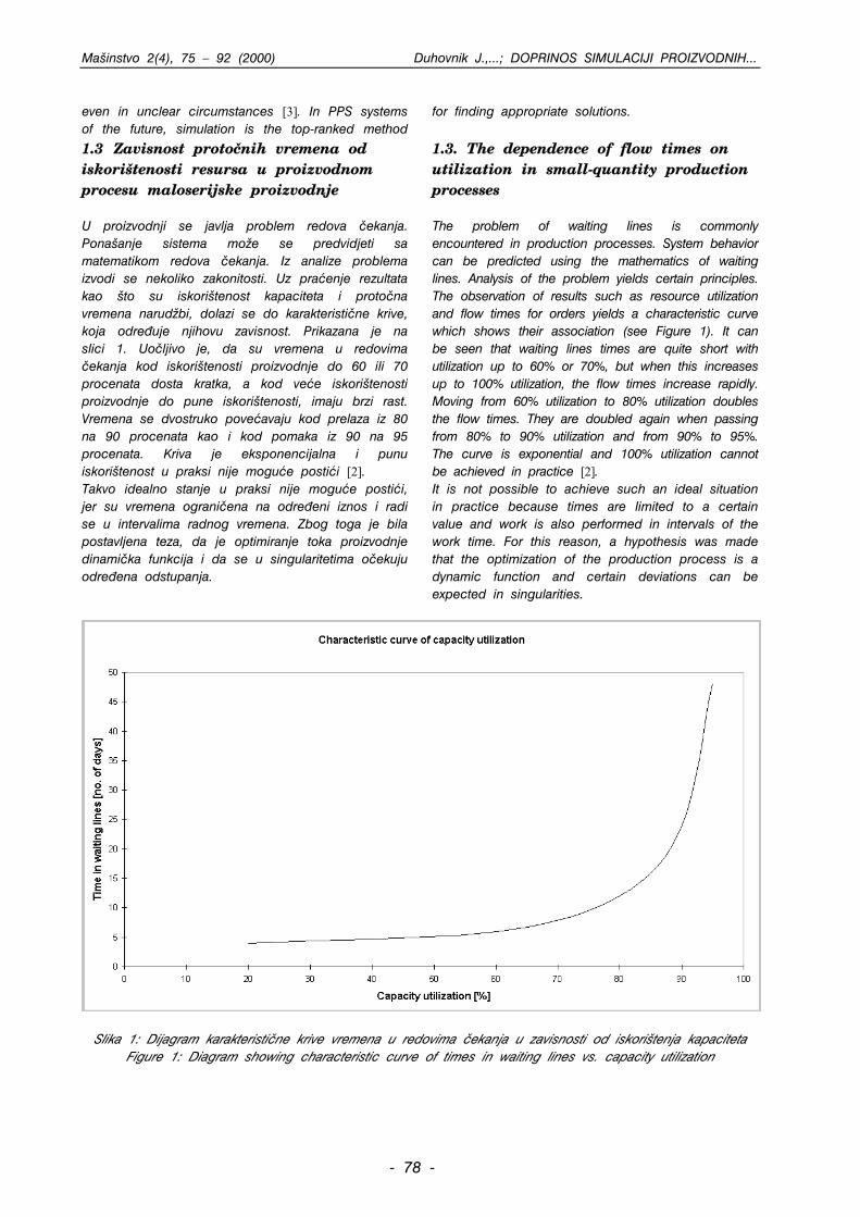
1.3 Zavisnost proto~nih vremena od iskoritenosti resursa u proizvodnom procesu maloserijske proizvodnje U proizvodnji se javlja problem redova ~ekanja. Ponaanje sistema mo`e se predvidjeti sa matematikom redova ~ekanja. Iz analize problema izvodi se nekoliko zakonitosti. Uz praenje rezultata kao to su iskoritenost kapaciteta i proto~na vremena narud`bi, dolazi se do karakteristi~ne krive, koja odre|uje njihovu zavisnost. Prikazana je na slici 1. Uo~ljivo je, da su vremena u redovima ~ekanja kod iskoritenosti proizvodnje do 60 ili 70 procenata dosta kratka, a kod vee iskoritenosti proizvodnje do pune iskoritenosti, imaju brzi rast. Vremena se dvostruko poveavaju kod prelaza iz 80 na 90 procenata kao i kod pomaka iz 90 na 95 procenata. Kriva je eksponencijalna i punu iskoritenost u praksi nije mogue postii [2]. Takvo idealno stanje u praksi nije mogue postii, jer su vremena ograni~ena na odre|eni iznos i radi se u intervalima radnog vremena. Zbog toga je bila postavljena teza, da je optimiranje toka proizvodnje dinami~ka funkcija i da se u singularitetima o~ekuju odre|ena odstupanja.
1.3. The dependence of flow times on utilization in small-quantity production processes The problem of waiting lines is commonly encountered in production processes. System behavior can be predicted using the mathematics of waiting lines. Analysis of the problem yields certain principles. The observation of results such as resource utilization and flow times for orders yields a characteristic curve which shows their association (see Figure 1). It can be seen that waiting lines times are quite short with utilization up to 60% or 70%, but when this increases up to 100% utilization, the flow times increase rapidly. Moving from 60% utilization to 80% utilization doubles the flow times. They are doubled again when passing from 80% to 90% utilization and from 90% to 95%. The curve is exponential and 100% utilization cannot be achieved in practice [2]. It is not possible to achieve such an ideal situation in practice because times are limited to a certain value and work is also performed in intervals of the work time. For this reason, a hypothesis was made that the optimization of the production process is a dynamic function and certain deviations can be expected in singularities.
Slika 1: Dijagram karakteristi~ne krive vremena u redovima ~ekanja u zavisnosti od iskoritenja kapaciteta
Figure 1: Diagram showing characteristic curve of times in waiting lines vs. capacity utilization
- 78 -
Mainstvo 2(4), 75 – 92 (2000) Duhovnik J.,...; DOPRINOS SIMULACIJI PROIZVODNIH...
2. ANALIZA STVARNOG PROIZVODNOG PROCESA KORI[TENJEM SIMULACIJA
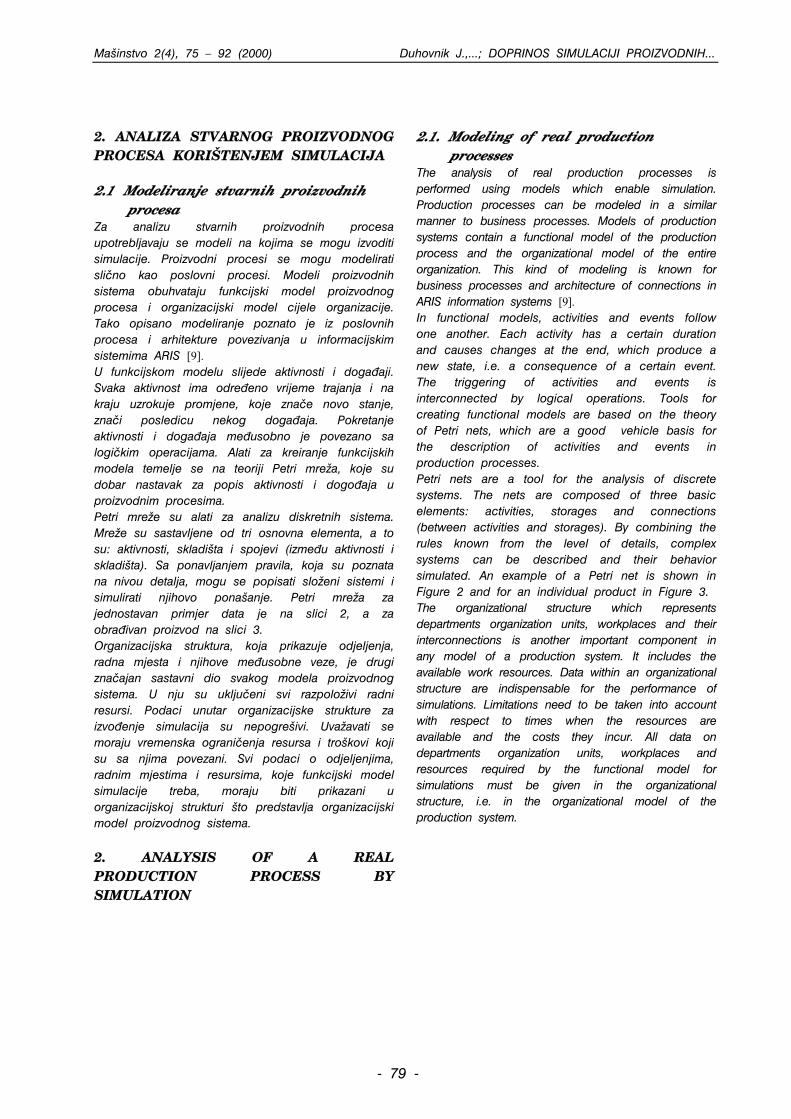
2.1 Modeliranje stvarnih proizvodnih procesa Za analizu stvarnih proizvodnih procesa upotrebljavaju se modeli na kojima se mogu izvoditi simulacije. Proizvodni procesi se mogu modelirati sli~no kao poslovni procesi. Modeli proizvodnih sistema obuhvataju funkcijski model proizvodnog procesa i organizacijski model cijele organizacije. Tako opisano modeliranje poznato je iz poslovnih procesa i arhitekture povezivanja u informacijskim sistemima ARIS [9]. U funkcijskom modelu slijede aktivnosti i doga|aji. Svaka aktivnost ima odre|eno vrijeme trajanja i na kraju uzrokuje promjene, koje zna~e novo stanje, zna~i posledicu nekog doga|aja. Pokretanje aktivnosti i doga|aja me|usobno je povezano sa logi~kim operacijama. Alati za kreiranje funkcijskih modela temelje se na teoriji Petri mre`a, koje su dobar nastavak za popis aktivnosti i dogo|aja u proizvodnim procesima. Petri mre`e su alati za analizu diskretnih sistema. Mre`e su sastavljene od tri osnovna elementa, a to su: aktivnosti, skladita i spojevi (izme|u aktivnosti i skladita). Sa ponavljanjem pravila, koja su poznata na nivou detalja, mogu se popisati slo`eni sistemi i simulirati njihovo ponaanje. Petri mre`a za jednostavan primjer data je na slici 2, a za obra|ivan proizvod na slici 3. Organizacijska struktura, koja prikazuje odjeljenja, radna mjesta i njihove me|usobne veze, je drugi zna~ajan sastavni dio svakog modela proizvodnog sistema. U nju su uklju~eni svi razpolo`ivi radni resursi. Podaci unutar organizacijske strukture za izvo|enje simulacija su nepogreivi. Uva`avati se moraju vremenska ograni~enja resursa i trokovi koji su sa njima povezani. Svi podaci o odjeljenjima, radnim mjestima i resursima, koje funkcijski model simulacije treba, moraju biti prikazani u organizacijskoj strukturi to predstavlja organizacijski model proizvodnog sistema.
2. ANALYSIS OF A REAL PRODUCTION PROCESS BY SIMULATION
2.1. Modeling of real production processes The analysis of real production processes is performed using models which enable simulation. Production processes can be modeled in a similar manner to business processes. Models of production systems contain a functional model of the production process and the organizational model of the entire organization. This kind of modeling is known for business processes and architecture of connections in ARIS information systems [9]. In functional models, activities and events follow one another. Each activity has a certain duration and causes changes at the end, which produce a new state, i.e. a consequence of a certain event. The triggering of activities and events is interconnected by logical operations. Tools for creating functional models are based on the theory of Petri nets, which are a good vehicle basis for the description of activities and events in production processes. Petri nets are a tool for the analysis of discrete systems. The nets are composed of three basic elements: activities, storages and connections (between activities and storages). By combining the rules known from the level of details, complex systems can be described and their behavior simulated. An example of a Petri net is shown in Figure 2 and for an individual product in Figure 3. The organizational structure which represents departments organization units, workplaces and their interconnections is another important component in any model of a production system. It includes the available work resources. Data within an organizational structure are indispensable for the performance of simulations. Limitations need to be taken into account with respect to times when the resources are available and the costs they incur. All data on departments organization units, workplaces and resources required by the functional model for simulations must be given in the organizational structure, i.e. in the organizational model of the production system.
- 79 -
Mainstvo 2(4), 75 – 92 (2000) Duhovnik J.,...; DOPRINOS SIMULACIJI PROIZVODNIH...
Slika 2: Primjer funkcijskog modela simulacije na osnovu Petri mre`a
Figure 2: Example of a functional model of simulation based on Petri nets
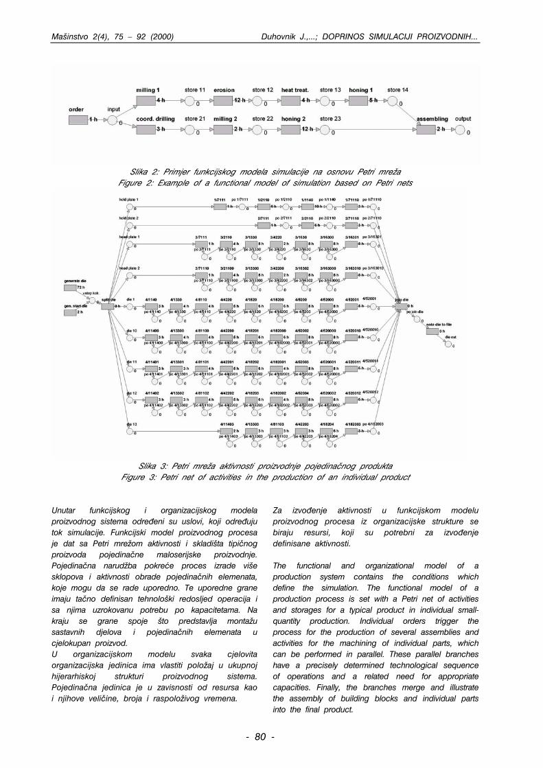
Slika 3: Petri mre`a aktivnosti proizvodnje pojedina~nog produkta
Figure 3: Petri net of activities in the production of an individual product Unutar funkcijskog i organizacijskog modela proizvodnog sistema odre|eni su uslovi, koji odre|uju tok simulacije. Funkcijski model proizvodnog procesa je dat sa Petri mre`om aktivnosti i skladita tipi~nog proizvoda pojedina~ne maloserijske proizvodnje. Pojedina~na narud`ba pokree proces izrade vie sklopova i aktivnosti obrade pojedina~nih elemenata, koje mogu da se rade uporedno. Te uporedne grane imaju ta~no definisan tehnoloki redosljed operacija i sa njima uzrokovanu potrebu po kapacitetama. Na kraju se grane spoje to predstavlja monta`u sastavnih djelova i pojedina~nih elemenata u cjelokupan proizvod. U organizacijskom modelu svaka cjelovita organizacijska jedinica ima vlastiti polo`aj u ukupnoj hijerarhiskoj strukturi proizvodnog sistema. Pojedina~na jedinica je u zavisnosti od resursa kao i njihove veli~ine, broja i raspolo`ivog vremena.
Za izvo|enje aktivnosti u funkcijskom modelu proizvodnog procesa iz organizacijske strukture se biraju resursi, koji su potrebni za izvo|enje definisane aktivnosti. The functional and organizational model of a production system contains the conditions which define the simulation. The functional model of a production process is set with a Petri net of activities and storages for a typical product in individual small-quantity production. Individual orders trigger the process for the production of several assemblies and activities for the machining of individual parts, which can be performed in parallel. These parallel branches have a precisely determined technological sequence of operations and a related need for appropriate capacities. Finally, the branches merge and illustrate the assembly of building blocks and individual parts into the final product.
- 80 -
Mainstvo 2(4), 75 – 92 (2000) Duhovnik J.,...; DOPRINOS SIMULACIJI PROIZVODNIH...
In the organizational model, each complete organizational unit has its own position within the entire hierarchical structure of the production system. Each individual unit is defined by its resources, and their number and the time they are available.
In order to perform the activities from the functional model of a production process, resources which are necessary for the performance of individual activities are selected from the organizational structure.
2.2 Definiranje uslova za simulaciju proizvodnog procesa Simulacije proizvodnje teku po koracima. Nove narud`be tra`e izvo|enje novih aktivnosti po odre|enom tehnolokom redoslijedu u svim uporednima granama Petri mre`a. Tok izvo|enja aktivnosti je kontroliran sa stanjima na mjestima ~ekanja prije i poslje aktivnosti. Objektima u tim skladitima dodjeljeni su `etoni. Njihov broj se kontrolira i uva`ava u uslovima razvrstavanja aktivnosti u odgovarajue grupe. Definisani su dvije grupi aktivnosti: • WkAj ... grupa aktivnosti trenutno u radu, Svaki elemenat te grupe aktivnosti u radu ima dodijeljeno vrijeme zavretka aktivnosti • WtAj ... grupa aktivnosti, koje trenutno ~ekaju na rad, Svaki elemenat te grupe aktivnosti ima dodijeljeno vrijeme po~etka ~ekanja na rad.
2.2. Definition of conditions for the simulation of production processes Simulations of production take place in steps. New orders require the performance of new activities in a certain technological sequence in all parallel branches of the Petri net. The course of performance of activities is controlled by states at the waiting sites before and after the activities. Tokens are assigned to objects in these storage sites. Their number is controlled and taken into account in the conditions for the classification of activities into sets. Two sets of activities are defined: • WkAj ... the set of currently performed activities; Each element of this set has a set time when the activity will be completed. • WtAj ... the set of activities currently waiting to be performed; Each element of this set has a set time when the activity will begin to wait to be performed.
2.2.1 Zna~ajni parametri za definiranje aktivnosti i uslova u procesu Aijk ... aktivnost j u lancu i na maini k, tAijk ... vrijeme trajanja aktivnosti j, WkAijk ... aktivnost u radu, WtAijk ... aktivnost koja trenutno ~eka na rad, tAend,j ... vrijeme zavretka aktivnosti tAend,j =tnow+ tAijk, tAstart,j ... vrijeme po~etka ~ekanja aktivnosti na rad, NR ... broj svih maina svih tipova, tRstart,k ... vrijeme po~etka radnog vremena maine k, tRend,k ... vrijeme zavretka radnog vremena maine k, Ravtime,k ... Boolean-ova promjenljiva, koja odre|uje dali je vrijeme u okviru radnog vremena maine k, Ravnum,k ... broj razpolo`ivih maina tipa k, Snum,ij ... broj objekata na mjestu ~ekanja ispred aktivnosti Aijk, Slim,ij ... gornja granica broja objekata na mjestu ~ekanja ispred aktivnosti Aijk, Ni ... broj svih uporednih lanaca aktivnosti,
Nij ... broj svih aktivnosti u lancu i, Nij,a ... broj svih aktivnosti, koje su trenutno u radu, Nij,w ... broj svih aktivnosti, koje trenutno ~ekaju na rad. Sve aktivnosti, prve u lancima u po~etku simulacije su u grupi aktivnosti koje ~ekaju na rad. To su one iz grupe svih aktivnosti Aijksa indeksom j=1. Trenutno vrijeme je tnow=0. za i = 1, Ni WtAijk = WtAijk + Ai,j=1,k 2.2.1. Important parameters for the determina-tion of activities and conditions in the process Aijk ... activity j in chain i on machine k tAijk ... duration of activity j WkAijk ... currently performed activity WtAijk ... activity currently waiting to be performed tAend,j ... time of completion tAend,j = tnow+ tAijk tAstart,j ... time of beginning of waiting for performance NR... number of all machines of all types
- 81 -
Mainstvo 2(4), 75 – 92 (2000) Duhovnik J.,...; DOPRINOS SIMULACIJI PROIZVODNIH...
tRstart,k ..time of the beginning of work time for machine k tRend,k ... time of the end of work time for machine k Ravtime,k .. Boolean variable which determines whether this time is within the framework of the work time for machine k Ravnum,k ... number of available machines of type k Snum,ij ... number of objects in the waiting site before activity Aijk Slim,ij ... upper limit of the number of objects in the waiting site before activity Aijk Ni ... number of all parallel chains of activities
Nij ... number of all activities in chain i
Nij,a ... number of all currently performed activities
Nij,w ... number of all activities currently waiting to be performed At the beginning of the simulation, the set of activities waiting to be performed contains all those activities which are the first in line in the chains, i.e. those from the set of all activities Aijk with an index j=1. The current time tnow=0. for i = 1, Ni
WtAijk = WtAijk + Aij=1k
Simulacije su uvjetovane doga|ajima. Promjene u mre`i simulacija nastaju poslije svakog doga|aja. U tom trenutku se donose odluke o narednom toku simulacije.
Simulations are conditioned by events. Changes in the simulation net occur upon each event. Decisions about the further course of the simulation are made at this point.
2.2.2 Tok simulacije po koracima Simulacija te~e po koracima. Novi korak nastupa kada se zbog izvrenog doga|aja mora provjeriti nastala promjena situacije. Vrijeme koraka se odre|uje na sljedei na~in: tnext = minmintAend,j,tchange gdje je: • mintAend,j vrijeme kada se zavri prva izme|u aktivnosti u radu, kad se osloba|aju resursi i elemenat koji je objekat ove aktivnosti postavi se ispred sledee aktivnosti. • tchange vrijeme kada nastupi promjena u raspolo`ivosti resursa (kada po~inje radna smjena ili se zavri). Kada se odredi tnext, stupamo u sledei korak, sa tim da izjedna~imo tnow = tnext.
2.2.2. Step-wise course of simulation Simulations are performed in a stepwise manner. A new step takes place when due to events which have occurred the changed situation needs to be checked. The time of a step is determined as follows: tnext = minmintAend,j,tchange where: • mintAend,j is the time when the first one of the currently performed activities is completed, which releases certain resources, and the object which is the subject of this activity is placed before the next activity in the chain. • tchange is the time when a change in the
availability of a resource occurs or when a work shift begins or ends. When tnext is determined, the new step is
embarked on by equating tnow = tnext.
2.2.3 Provjeravanje utjecaja i vrenje akcija U novom trenutku provjeravamo: • koji resursi su u tom vremenu na raspolaganju, za k = 1, NR if(tRstart,k < tnow < tRend,k) onda Ravtime,k = true • koje aktivnosti u radu se zavre, odstranimo ih iz grupe aktivnosti u radu, osloba|amo resurse koje su okupirale (poveavamo broj raspolo`ivih maina tipa k za 1) i poveavamo broj objekata u skladitu poslje ove aktivnosti,
za m = 1, Nij,a ako je (tAend,m = tnow) onda je: WkAijk = WkAijk - WkAm,ijk Ravnum,k = Ravnum,k + 1 Snum,ij+1 = Snum,ij+1 + 1 • koje od svih aktivnosti u mre`i s obzirom na stanje u skladitima mogu po~eti, svrstavamo ih u grupu aktivnosti koje ~ekaju na rad i podesimo vrijeme po~etka ~ekanja na rad na trenuta~no vrijeme,
2.2.3. Verification of conditions and performance of actions
- 82 -
Mainstvo 2(4), 75 – 92 (2000) Duhovnik J.,...; DOPRINOS SIMULACIJI PROIZVODNIH...
In the next moment, the following should be checked: • which resources are available at the time, for k = 1, NR
if(tRstart,k < tnow < tRend,k) then Ravtime,k = true • which of the currently performed activities will be completed; these will be removed from the set of currently performed activities and the resources they occupied will be freed (the number of available type k machines is increased by 1) and the number of objects in the storage after this activity is increased,
for m = 1, Nij,a if(tAend,m = tnow) then WkAijk = WkAijk - WkAm,ijk Ravnum,k = Ravnum,k + 1 Snum,ij+1 = Snum,ij+1 + 1 • which of all the activities in the net can begin with respect to the situation in the storage sites; these are placed into the set of activities waiting to be performed and the time of the beginning of waiting to be performed is set to the current time,
za i = 1, Ni and j = 1, Nij ako je (Snum,ij > 0 && Snum,ij+1 < Slim,ij+1) onda je za m = 1, Snum,ij WtAijk = WtAijk + Aijk tAstart,j = tnow Snum,ij = 0 • koje su aktivnosti koje ~ekaju na rad, ukupno sa novima aktivnostima u tom stanju da ispunjavaju uslove i mogu se po~eti odvijati. One se svrstavaju u grupu aktivnosti u radu i odvoje se iz grupe aktivnosti koje ~ekaju na rad, a potom se zabilje`e maine koje zauzimaju (smanji se broj raspolo`ivih maina tipa k za 1). za m = 1, Nij,w ako je (Ravnum,k > 0 && Ravtime,k = true) onda je WkAijk = WkAijk + WtAm,ijk tAend,m = tnow + tAm,ijk WtAijk = WtAijk - WtAm,ijk Ravnum,k = Ravnum,k - 1 Za i = 1, Ni i j= 1, Nij
if(Snum,ij > 0 && Snum,ij+1 < Slim,ij+1) then for m = 1, Snum,ij WtAijk = WtAijk + Aijk tAstart,j = tnow Snum,ij = 0 • which of the activities waiting to be performed, including the new ones, fulfill the conditions for the beginning of performance. These are placed into the set of currently performed activities and eliminated from the set of activities waiting to be performed. A note is made of which machines they occupy (the number of available type k machines is reduced by 1). for m = 1, Nij,w if(Ravnum,k > 0 && Ravtime,k = true) then WkAijk = WkAijk + WtAm,ijk tAend,m = tnow + tAm,ijk WtAijk = WtAijk - WtAm,ijk Ravnum,k = Ravnum,k – 1 for i = 1, Ni and j = 1, Nij
3. UTJECAJI NA PROIZVODNI PROCES
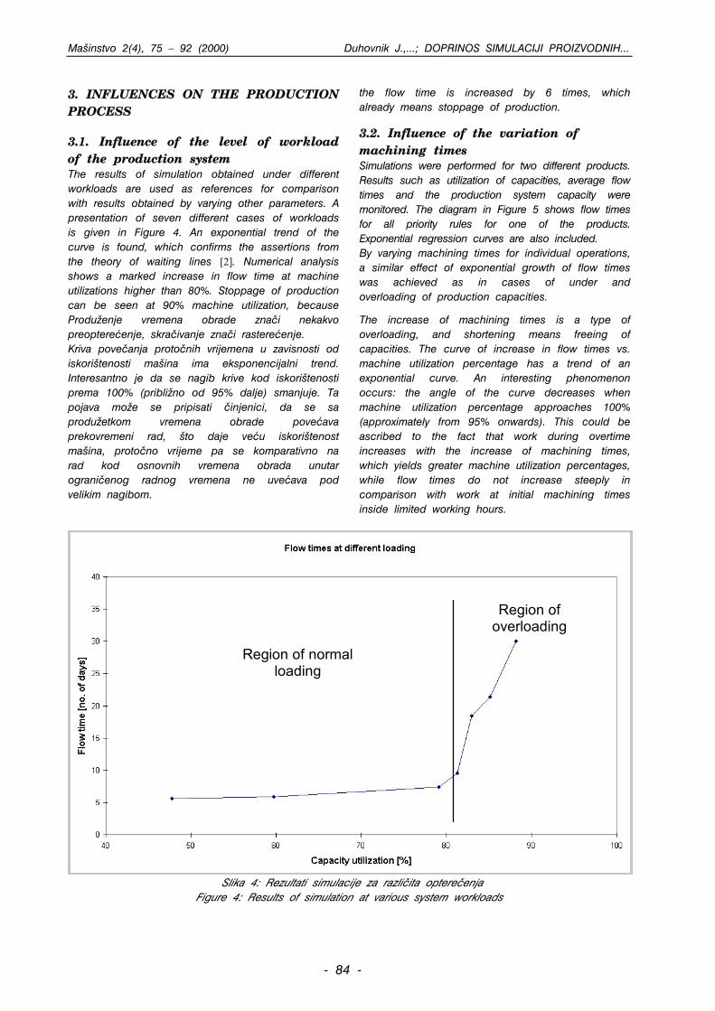
3.1 Utjecaj nivoa optereenja proizvodnog sistema Podeavanje simulacija na razli~ite nivoe optereenja uzima se kao referenca za upore|ivanje sa rezultatima kod ostalih promjenljivih parametara. Prikaz za sedam razli~itih primjera optereenja dat je na slici 4. Vidi se eksponencijalni trend krive, to potvr|uje navode iz teorije redova ~ekanja [2]. Kod numeri~ke analize se vidi izrazit skok proto~nog vremena iznad 80% iskoritenosti. Zastoj proizvodnje je ustanovljen kod 90% iskoritenosti,
jer se proto~no vrijeme uve~ava za 6-puta, to u proizvodnji ve zna~i zastoj.
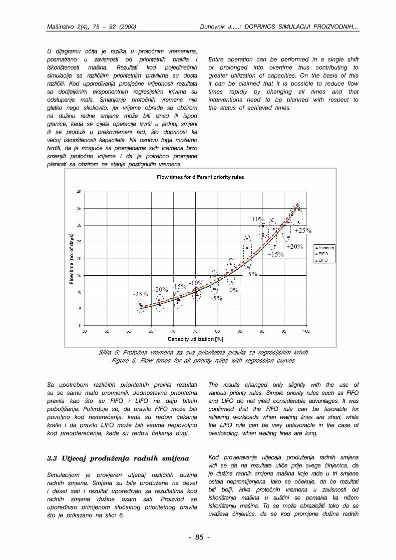
3.2 Utjecaj promjena vremena obrade Izvrene su simulacije za dva razli~ita proizvoda. Praeni su rezultati kao to su iskoritenost kapaciteta, prosje~no proto~no vrijeme i kapacitet proizvodnog sistema. Na slici 5 su u dijagramu prikazana proto~na vremena za sva prioritetna pravila jednog od proizvoda. Ustanovljene su i eksponencijalne regresijske krive. Sa promjenama vremena obrada pojedina~nih operacija posti`e se sli~an efekat eksponencijalnog rasta proto~nih vremena, kao to je primjer preoptereenja rastereenja proizvodnih kapaciteta.
- 83 -
Mainstvo 2(4), 75 – 92 (2000) Duhovnik J.,...; DOPRINOS SIMULACIJI PROIZVODNIH...
3. INFLUENCES ON THE PRODUCTION PROCESS
3.1. Influence of the level of workload of the production system The results of simulation obtained under different workloads are used as references for comparison with results obtained by varying other parameters. A presentation of seven different cases of workloads is given in Figure 4. An exponential trend of the curve is found, which confirms the assertions from the theory of waiting lines [2]. Numerical analysis shows a marked increase in flow time at machine utilizations higher than 80%. Stoppage of production can be seen at 90% machine utilization, because
the flow time is increased by 6 times, which already means stoppage of production.
3.2. Influence of the variation of machining times Simulations were performed for two different products. Results such as utilization of capacities, average flow times and the production system capacity were monitored. The diagram in Figure 5 shows flow times for all priority rules for one of the products. Exponential regression curves are also included. By varying machining times for individual operations, a similar effect of exponential growth of flow times was achieved as in cases of under and overloading of production capacities.
Produ`enje vremena obrade zna~i nekakvo preoptereenje, skra~ivanje zna~i rastereenje. Kriva pove~anja proto~nih vrijemena u zavisnosti od iskoritenosti maina ima eksponencijalni trend. Interesantno je da se nagib krive kod iskoritenosti prema 100% (pribli`no od 95% dalje) smanjuje. Ta pojava mo`e se pripisati ~injenici, da se sa produ`etkom vremena obrade poveava prekovremeni rad, to daje veu iskoritenost maina, proto~no vrijeme pa se komparativno na rad kod osnovnih vremena obrada unutar ograni~enog radnog vremena ne uveava pod velikim nagibom.
The increase of machining times is a type of overloading, and shortening means freeing of capacities. The curve of increase in flow times vs. machine utilization percentage has a trend of an exponential curve. An interesting phenomenon occurs: the angle of the curve decreases when machine utilization percentage approaches 100% (approximately from 95% onwards). This could be ascribed to the fact that work during overtime increases with the increase of machining times, which yields greater machine utilization percentages, while flow times do not increase steeply in comparison with work at initial machining times inside limited working hours.
Region of normalloading
Region ofoverloading
Slika 4: Rezultati simulacije za razli~ita optere~enja Figure 4: Results of simulation at various system workloads
- 84 -
Mainstvo 2(4), 75 – 92 (2000) Duhovnik J.,...; DOPRINOS SIMULACIJI PROIZVODNIH...
U dijagramu o~ita je razlika u proto~nim vremenima, posmatrano u zavisnosti od prioritetnih pravila i iskoritenosti maina. Rezultati kod pojedina~nih simulacija sa razli~itim prioritetnim pravilima su dosta razli~iti. Kod upore|ivanja prosje~ne vrijednosti rezultata sa dodjeljenim eksponentnim regresijskim krivima su odstupanja mala. Smanjenje proto~nih vremena nije glatko nego skokovito, jer vrijeme obrade sa obzirom na du`inu radne smjene mo`e biti iznad ili ispod granice, kada se cijela operacija izvri u jednoj smjeni ili se produ`i u prekovremeni rad, to doprinosi ka veoj iskoritenosti kapaciteta. Na osnovu toga mo`emo tvrditi, da je mogue sa promjenama svih vremena brzo smanjiti proto~no vrijeme i da je potrebno promjene planirati sa obzirom na stanje postignutih vremena.
Entire operation can be performed in a single shift or prolonged into overtime thus contributing to greater utilization of capacities. On the basis of this it can be claimed that it is possible to reduce flow times rapidly by changing all times and that interventions need to be planned with respect to the status of achieved times.
-15%-20%-25%
-10%
-5%0%
+5%
+10%
+15%+20%
+25%
Slika 5: Proto~na vremena za sva prioritetna pravila sa regresijskim krivih
Figure 5: Flow times for all priority rules with regression curves
Sa upotrebom razli~itih prioritetnih pravila rezultati su se samo malo promjenili. Jednostavna prioritetna pravila kao to su FIFO i LIFO ne daju bitnih poboljanja. Potvr|uje se, da pravilo FIFO mo`e biti povoljno kod rastereenja, kada su redovi ~ekanja kratki i da pravilo LIFO mo`e biti veoma nepovoljno kod preoptereenja, kada su redovi ~ekanja dugi.
The results changed only slightly with the use of various priority rules. Simple priority rules such as FIFO and LIFO do not yield considerable advantages. It was confirmed that the FIFO rule can be favorable for relieving workloads when waiting lines are short, while the LIFO rule can be very unfavorable in the case of overloading, when waiting lines are long.
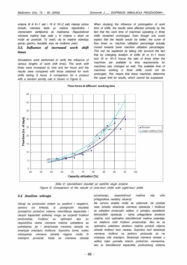
3.3 Utjecaj produ`enja radnih smijena Simulacijom je provjeren utjecaj razli~itih du`ina radnih smjena. Smjena su bile produ`ene na devet i deset sati i rezultat upore|ivan sa rezultatima kod radnih smjena du`ine osam sati. Proizvod se upore|ivao primjenom slu~ajnog prioritetnog pravila to je prikazano na slici 6.
Kod provjeravanja utjecaja produ`enja radnih smjena vidi se da na rezultate uti~e prije svega ~injenica, da je du`ina radnih smjena maina koje rade u tri smjene ostala nepromijenjena. Iako se o~ekuje, da e rezultati biti bolji, kriva proto~nih vremena u zavisnosti od iskoritenja maina u sutini se pomakla ka ni`em iskoritenju maina. To se mo`e obrazlo`iti tako da se uva`ava ~injenica, da se kod promjene du`ine radnih
- 85 -
Mainstvo 2(4), 75 – 92 (2000) Duhovnik J.,...; DOPRINOS SIMULACIJI PROIZVODNIH...
smjena (8 ili 8+1 sati i 16 ili 16+2 sati) mijenja odnos izme|u vremena kada su maine razpolo`ive i vremenskim zahtijevima za mainama. Razpolo`ivost vremena maina koje rade u tri smjena u stvari ne mo`e se poveati. To zna~i, da te maine odre|uju gornju granicu rezultata, koju ne mo`emo prei.
3.3. Influence of increased work shift times Simulations were performed to verify the influence of various lengths of work shift times. The work shift times were increased to nine and ten hours and the results were compared with those obtained for work shifts lasting 8 hours. A comparison for a product with a random priority rule is shown in Figure 6.
When studying the influence of prolongation of work time of shifts, the results were affected primarily by the fact that the work time of machines operating in three shifts remained unchanged. Even though one could expect that the results would be better, the curve of flow times vs. machine utilization percentage actually moved towards lower machine utilization percentages. This can be explained by taking into account the fact that by changing duration of shifts (8 or 8+1 hours and 16 or 16+2 hours) the ratio of times when the machines are available to time requirements for machines was changed as well. The available time of machines working in three shifts could not be prolonged. This means that these machines determine the upper limit for results, which cannot be surpassed.
Slika 6: Upore|ivani rezultati za razli~ito duge smjene
Figure 6: Comparison of the results of nine-hour shifts with eight-hour shifts
3.4 Analiza uticaja Uticaji na proizvodni sistem su pozitivni i negativni, zavisno od kriterija. Iz postignutih rezultata (prosje~no proto~no vrijeme, iskoritenje kapaciteta i ukupni kapaciteti sistema) mogu se ocijeniti trokovi proizvodnje. Trokovi su optimalni ako su raspolo`iva radna vremena maina uskla|ena sa potrebama, jer i skraivanje vremena obrada ne smanjuje zna~ajno trokove. Suprotno tome, svako odstupanje vremena obrada nagore mo`e ih zna~ajno poveati. Kada se vremena obrada
poveavaju, raspolo`ivost maina nije vie prilago|ena nastaloj situaciji. Na osnovu analize mo`e se ustanoviti, da postoje veze izme|u skraenja vremena operacija i trokova za odre|eni proizvodni sistem. U primjeru razra|enih tehnolokih operacija i njima prilago|ene strukture maina, kod optimalne iskoritenosti maina pojavljaju se relativno niski trokovi proizvodnje. Ako se za optimalnu odabranu strukturu maina produ`i vrijeme obrade trokovi brzo narastu. Suprotno kod skraenja vremena, trokovi na jedinicu proizvoda se ne smanjuju vie zna~ajno. Skraenje vremena obrade u velikoj mjeri poma`e kraim proto~nim vremenima, ako je iskoritenost kapaciteta proizvodnog sistema
- 86 -
Mainstvo 2(4), 75 – 92 (2000) Duhovnik J.,...; DOPRINOS SIMULACIJI PROIZVODNIH...
iznad 80%. Ako je manje, osloba|aju se kapaciteti i u manjem obimu i proto~na vremena.
3.4. Analysis of the influences Influences on a production system can be positive or negative, depending on the criteria. Production costs can be estimated from results obtained for average flow time, resource utilization and total system capacity. The costs are optimal if the available working times of machines are in line with needs, since a reduction in machining times does not significantly reduce costs. However, any increase in machining times can significantly increase costs. The availability of machines is not adapted to the circumstances of increased machining times.
On the basis of the analysis it can be established that there is a relationship between shortening the time of operations and the costs for a certain production system. In the case of elaborate technological operations and the machine and device structures adapted to them, the costs of operation are relatively low in optimal machine utilization. If at the optimal structure of the machines the machining time is increased, the costs increase rapidly. On the other hand, costs per product unit no longer increase significantly if the times are shortened. Shortening of the machining times considerably contributes to shorter flow times if the utilization of capacities of the production system exceeds 80%. However, if is lower, capacities are freed, and to a smaller extent also the flow time.
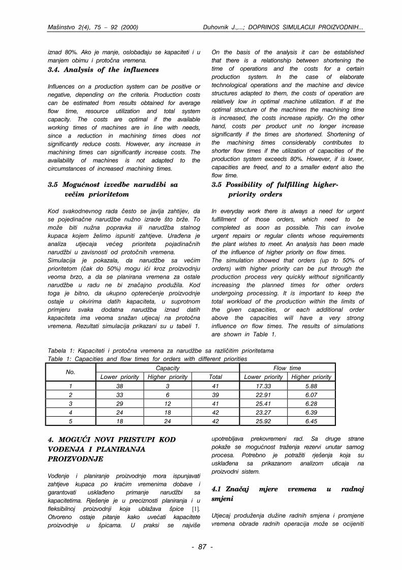
3.5 Mogunost izvedbe narud`bi sa ve~im prioritetom Kod svakodnevnog rada ~esto se javlja zahtijev, da se pojedina~ne narud`be nu`no izrade to br`e. To mo`e biti nu`na popravka ili narud`ba stalnog kupaca kojem `elimo ispuniti zahtjeve. Ura|ena je analiza utjecaja veeg prioriteta pojadina~nih narud`bi u zavisnosti od proto~nih vremena. Simulacija je pokazala, da narud`be sa veim prioritetom (~ak do 50%) mogu ii kroz proizvodnju veoma brzo, a da se planirana vremena za ostale narud`be u radu ne bi zna~ajno produ`ila. Kod toga je bitno, da ukupno optereenje proizvodnje ostaje u okvirima datih kapaciteta, u suprotnom primjeru svaka dodatna narud`ba iznad datih kapaciteta ima veoma sna`an utjecaj na proto~na vremena. Rezultati simulacija prikazani su u tabeli 1.
3.5 Possibility of fulfilling higher- priority orders In everyday work there is always a need for urgent fulfillment of those orders, which need to be completed as soon as possible. This can involve urgent repairs or regular clients whose requirements the plant wishes to meet. An analysis has been made of the influence of higher priority on flow times. The simulation showed that orders (up to 50% of orders) with higher priority can be put through the production process very quickly without significantly increasing the planned times for other orders undergoing processing. It is important to keep the total workload of the production within the limits of the given capacities, or each additional order above the capacities will have a very strong influence on flow times. The results of simulations are shown in Table 1.
Tabela 1: Kapaciteti i proto~na vremena za narud`be sa razli~itim prioritetama Table 1: Capacities and flow times for orders with different priorities
Capacity Flow time No.
Lower priority Higher priority Total Lower priority Higher priority
1 38 3 41 17.33 5.88 2 33 6 39 22.91 6.07 3 29 12 41 25.41 6.28 4 24 18 42 23.27 6.39 5 18 24 42 25.92 6.45
4. MOGU]I NOVI PRISTUPI KOD VO\ENJA I PLANIRANJA PROIZVODNJE Vo|enje i planiranje proizvodnje mora ispunjavati zahtjeve kupaca po kraim vremenima dobave i garantovati uskla|eno primanje narud`bi sa kapacitetima. Rjeenje je u preciznosti planiranja i u fleksibilnoj proizvodnji koja ubla`ava pice [1]. Otvoreno ostaje pitanje kako uveati kapacitete proizvodnje u picama. U praksi se najvie
upotrebljava prekovremeni rad. Sa druge strane poka`e se mogunost tra`enja rezervi unutar samog procesa. Potrebno je potra`iti rjeenja koja su uskla|ena sa prikazanom analizom uticaja na proizvodni sistem.
4.1 Zna~aj mjere vremena u radnoj smjeni Utjecaj produ`enja du`ine radnih smjena i promjene vremena obrade radnih operacija mo`e se ocijeniti
- 87 -
Mainstvo 2(4), 75 – 92 (2000) Duhovnik J.,...; DOPRINOS SIMULACIJI PROIZVODNIH...
iz vremena obrade prikazanih po sastavnim dijelovima. To su lanci radova u stubnom dijagramu, koji ta~no prikazuje potrebe po mainama zavisno od sastavnih djelova.
4. POSSIBLE NEW APPROACHES TO PRODUCTION MANAGEMENT AND PLANNING Production management and planning must fulfill the requirements of the clients for shorter delivery times and ensure that the acceptance of orders be harmonized with the capacities. The solution lies in accurate planning and flexible production, which is capable of cushioning peak workloads [1]. The question of how to increase production capacities at
peaks remains open. In practice, overtime work is used most. On the other hand, there is a possibility of finding reserves inside the process. Solutions should be found in accordance with the analysis of the influences on the production process, which has been performed.
4.1. Significance of a unit of work in a work shift The influence of prolongation of work shift times and variation of machining times for individual work operations can be assessed from the histogram of machining times by building blocks chains of work operations, which clearly show the requirements for machines with respect to building blocks. Each part of the entire order requires a certain sequence of operations which must be performed on it.
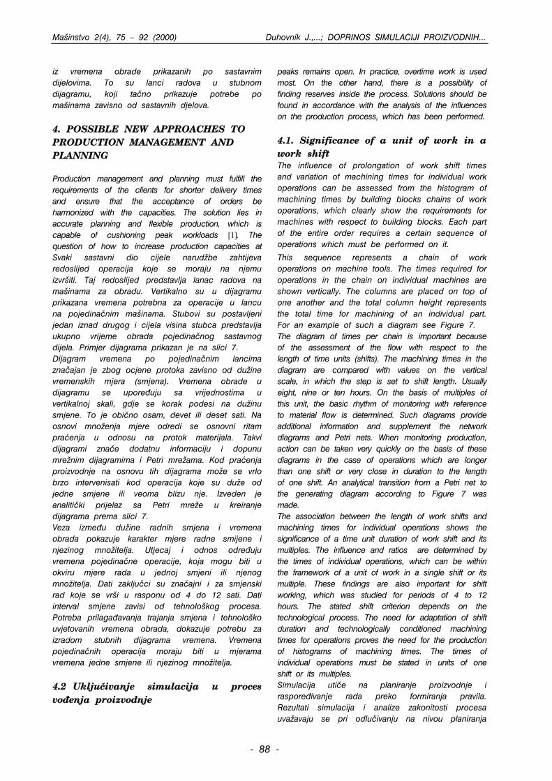
Svaki sastavni dio cijele narud`be zahtijeva redoslijed operacija koje se moraju na njemu izvriti. Taj redoslijed predstavlja lanac radova na mainama za obradu. Vertikalno su u dijagramu prikazana vremena potrebna za operacije u lancu na pojedina~nim mainama. Stubovi su postavljeni jedan iznad drugog i cijela visina stubca predstavlja ukupno vrijeme obrada pojedina~nog sastavnog dijela. Primjer dijagrama prikazan je na slici 7. Dijagram vremena po pojedina~nim lancima zna~ajan je zbog ocjene protoka zavisno od du`ine vremenskih mjera (smjena). Vremena obrade u dijagramu se upore|uju sa vrijednostima u vertikalnoj skali, gdje se korak podesi na du`inu smjene. To je obi~no osam, devet ili deset sati. Na osnovi mno`enja mjere odredi se osnovni ritam praenja u odnosu na protok materijala. Takvi dijagrami zna~e dodatnu informaciju i dopunu mre`nim dijagramima i Petri mre`ama. Kod praenja proizvodnje na osnovu tih dijagrama mo`e se vrlo brzo intervenisati kod operacija koje su du`e od jedne smjene ili veoma blizu nje. Izveden je analiti~ki prijelaz sa Petri mre`e u kreiranje dijagrama prema slici 7. Veza izme|u du`ine radnih smjena i vremena obrada pokazuje karakter mjere radne smijene i njezinog mno`itelja. Utjecaj i odnos odre|uju vremena pojedina~ne operacije, koja mogu biti u okviru mjere rada u jednoj smjeni ili njenog mno`itelja. Dati zaklju~ci su zna~ajni i za smjenski rad koje se vri u rasponu od 4 do 12 sati. Dati interval smjene zavisi od tehnolokog procesa. Potreba prilaga|avanja trajanja smjena i tehnoloko uvjetovanih vremena obrada, dokazuje potrebu za izradom stubnih dijagrama vremena. Vremena pojedina~nih operacija moraju biti u mjerama vremena jedne smjene ili njezinog mno`itelja.
This sequence represents a chain of work operations on machine tools. The times required for operations in the chain on individual machines are shown vertically. The columns are placed on top of one another and the total column height represents the total time for machining of an individual part. For an example of such a diagram see Figure 7. The diagram of times per chain is important because of the assessment of the flow with respect to the length of time units (shifts). The machining times in the diagram are compared with values on the vertical scale, in which the step is set to shift length. Usually eight, nine or ten hours. On the basis of multiples of this unit, the basic rhythm of monitoring with reference to material flow is determined. Such diagrams provide additional information and supplement the network diagrams and Petri nets. When monitoring production, action can be taken very quickly on the basis of these diagrams in the case of operations which are longer than one shift or very close in duration to the length of one shift. An analytical transition from a Petri net to the generating diagram according to Figure 7 was made. The association between the length of work shifts and machining times for individual operations shows the significance of a time unit duration of work shift and its multiples. The influence and ratios are determined by the times of individual operations, which can be within the framework of a unit of work in a single shift or its multiple. These findings are also important for shift working, which was studied for periods of 4 to 12 hours. The stated shift criterion depends on the technological process. The need for adaptation of shift duration and technologically conditioned machining times for operations proves the need for the production of histograms of machining times. The times of individual operations must be stated in units of one shift or its multiples.
4.2 Uklju~ivanje simulacija u proces vo|enja proizvodnje
Simulacija uti~e na planiranje proizvodnje i raspore|ivanje rada preko formiranja pravila. Rezultati simulacija i analize zakonitosti procesa uva`avaju se pri odlu~ivanju na nivou planiranja
- 88 -
Mainstvo 2(4), 75 – 92 (2000) Duhovnik J.,...; DOPRINOS SIMULACIJI PROIZVODNIH...
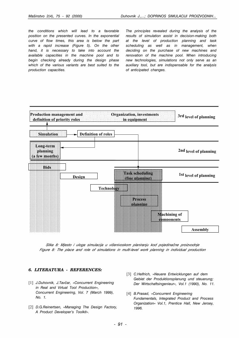
proizvodnje i razpore|ivanja rada (prvi i drugi nivo planiranja), kao to je prikazano na slici 8. Podeavanja kod simulacija moraju odgovarati proizvodnom procesu, jer mogu bitno uticati na rezultate. U slu~aju, kada obra|ivani primjer odstupa od ve analiziranih, potrebna je nova simulacija pod drugim uvjetima i podeavanjima. Zna~ajno je uva`avanje uskla|enosti novih produkata sa tehnolokim mogunostima i strukturom maina ve u razvojno konstrukcijonoj fazi produkata. Produkti sa jednakom namjenom su razli~ito smiljeni i izvedeni sa razli~itim tehnolokim postupcima.
4.2. Introduction of simulations into the process of production management
Simulation affects production planning and task scheduling by creating rules. The results of simulation and analysis of the principles of the process are taken into account in decision-making at the levels of production planning and task scheduling (the first and second level of planning), as shown in Figure 8. Settings in simulation must correspond to the production process, because they can significantly affect the results. If a studied case deviates from previously analyzed ones, a new simulation is required under different conditions, i.e. with different settings. New products must be harmonized with the technological possibilities and the structure of the machine pool already at the design-developmental phase. Products with identical purposes can have different designs and can be produced with different technological procedures.
Slika 7: Dijagram vremena obrada za sve lance operacija po mainama
Figure 7: Diagram of machining times for each individual chain per machine tool Sa simulacijama se mo`e ustanoviti, koja od razli~itih varijanti najbolje odgovara raspolo`ivim proizvodnim kapacitetima. Odluke o uvo|enju novih tehnologija i nabavci nove opreme sa ciljem skraivanja vremena obrade temelje se na izvedenim simulacijama. Simulacije omoguavaju analizu situacija, koje su providljive u budunosti. Mogu se saznati posljedice i mogue koristi, koje bi se dogodile tokom renoviranja mainskog parka ili uvo|enjem novih tehnologija. Simulacije nude mogunost provjeravanja planiranih promjena. Radi se o odlu~ivanju na gornjem treem nivou planiranja. Uva`avanje rezultata simulacija kod odlu~ivanja na nivou vodstva proizvodnje i izvo|enje simulacija kroz du`e razdoblje, omoguava upotrebu
analiziranih rezultata kod odluka npr. o nabavci novih maina, na nivou vodstva. Simulations can be used to establish which of several variants corresponds best to the available production capacity. Decisions on the introduction of new technologies and purchases of new equipment in order to shorten manufacturing times are based on the performed simulations. Simulations enable analysis of situations anticipated in the future. The consequences and possible benefits of renovation of the machine pool or introduction of new technologies can be identified. Simulations provide a possibility to check the planned changes. This involves decision-making at the upper
- 89 -
Mainstvo 2(4), 75 – 92 (2000) Duhovnik J.,...; DOPRINOS SIMULACIJI PROIZVODNIH...
third level of planning. Taking the results of simulations into account in decision-making at the level of production management and performance of simulations over a longer period of time enables the
use of analyzed results in decision-making, for example regarding the purchase of new machines at the managerial level.
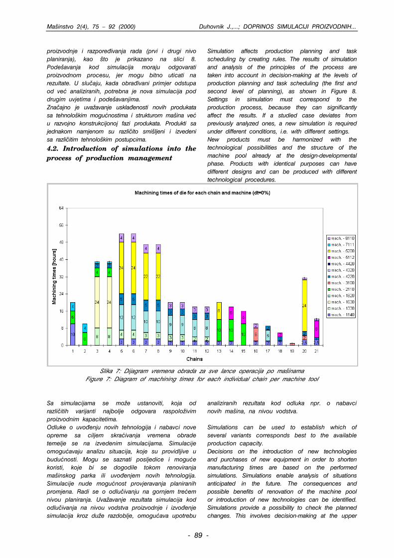
5. ZAKLJU^AK Simulacije proizvodih procesa va`an su faktor u procesu optimiranja proizvodnje. U praksi, do sada su se simulacije prihvatale kod planiranja monta`e serijske proizvodnje, dok su kod planiranja u pojedina~noj proizvodnji, zbog zna~ajnog stepena nepredvidljivosti, bolji alati za projektno vo|enje. ^injenica je da pojedina~na proizvodnja ne opravdava uvijek dugotrajne simulacije i zahtjeva brze odluke.
5. CONCLUSION Simulations of production processes are an important link in the process of optimizing production. In practice, they have become established in planning assembly in mass production, while tools for project management are more appropriate for the planning of individual production due to the considerable degree of unpredictability. It is a fact that individual production does not always justify long-term simulations and requires quick decision-making.
U okolini, gdje su pojedina~ni proizvodi rezultat varijantnog konstruiranja, mogu se u pojedina~noj proizvodnji uz pomo simulacija utvrditi odre|ene zakonitosti. Analiza simulacija dovodi do novih saznanja. Pa`nja mora da se usmjeri na vezu izme|u ukupne du`ine operacija za pojedina~ne dijelove proizvoda i du`inu radnih smjena. Za o~ito predstavu vremena obrada po lancima i resursima va`an je stubni dijagram (slika 7), koja ima korak u skali podeen na du`inu radnog vremena u smjeni. Prati se uticaj produ`enja i skraenja vremena obrada na proto~no vrijme i trokove proizvodnje. Kod spoznaje veza izme|u ukupnih du`ina operacija u jednoj grani za pojedina~ni dio produkata i du`inu radnog vremena u smjeni, utvrdi se skokovito mjenjanje proto~nih vremena. Ve malo skraenje vremena obrade, koje omoguava zavravanje operacije unutar jedne izmene, mo`e donijeti velike koristi kod proto~nih ~asova i posljedi~no kod trokova proizvodnje. Provjerena je situacija, kada imaju odre|ene narud`be prioritet i tra`e brz odaziv. Rezultat je pokazao, da sistem mo`e podnijeti i vei broj narud`bi (do 50%) sa veim prioritetom, ako je ukupno optereenje konstantno. To zna~i, da se mo`e pojedina~nim narud`bama bitno skratiti proto~no vrijeme, bez zna~ajnih posljedica na proto~na vremena ostalih narud`bi. Iz svih rezultata mo`e se zaklju~iti, da je u proizvodnji bitno osigurati uvjete, koji e je dovesti u povoljan polo`aj na predstavljenim krivim. Na eksponentnoj krivoj proto~nih vremena to je ispod podru~ija brzog rasta nagiba (slika 5). Sa druge strane potrebno je uva`avati razpolo`ive kapacitete u mainskom parku i ve u fazi konstruiranja provjeravati, koje od razli~itih varijanti najbolje odgovaraju proizvodnim kapacitetima. Zakonitosti, koje su postignute uz analizu rezultata simulacija, poma`u kod odluka na nivou planiranja i
raspore|ivanja rada kao i kod vo|enja proizvodnje, kada se donose odluke o nabavci novih maina i renoviranju mainskog parka. U procesu uvo|enja novih tehnologija simulacije nisu samo pomono sredstvo, nego nu`no potreban alat za analizu predvidljivih promjena. In environments in which individual products are the result of variant design, such as tools for example, certain principles of individual production can be established using simulations. The analysis of simulations leads to new findings. Attention need to be focused on the association between the total length of operations for individual product parts and the length of work shifts. Histograms are important for clear presentation of machining times, by chains and by resources (Figure 7). In such diagrams, steps in the scale are set to the length of work time in a shift. The influence of the increasing and shortening of machining times on flow time and production costs was observed. When establishing the connections between the total length of operations in a chain for an individual product part and the length of work time in a shift, steep fluctuations of flow times are established. Even a small reduction in machining times, which enables completion of an operation within one shift, can bring large benefits both in terms of flow times and consequentially in terms of production costs. A situation was tested in which certain orders have priority and require a rapid response. The results showed that systems can withstand even a greater number (up to 50%) of higher priority orders if the total workload is constant. This means that the flow times of individual orders can be considerably shortened without marked consequences for the flow times of other orders. It can be concluded from all the results that within the production process it is important to provide
- 90 -
Mainstvo 2(4), 75 – 92 (2000) Duhovnik J.,...; DOPRINOS SIMULACIJI PROIZVODNIH...
the conditions which will lead to a favorable position on the presented curves. In the exponential curve of flow times, this area is below the part with a rapid increase (Figure 5). On the other hand, it is necessary to take into account the available capacities in the machine pool and to begin checking already during the design phase which of the various variants are best suited to the production capacities.
The principles revealed during the analysis of the results of simulation assist in decision-making both at the level of production planning and task scheduling as well as in management, when deciding on the purchase of new machines and renovation of the machine pool. When introducing new technologies, simulations not only serve as an auxiliary tool, but are indispensable for the analysis of anticipated changes.
Task scheduling(fine planning)
Long-termplanning
(a few months)
Bids
Design
Technology
Processplanning
Machining ofcomponents
Assembly
Production management anddefinition of priority roles
Organization, investmentsin equipment
Definition of roles
3rd level of planning
2nd level of planning
1st level of planning
Simulation
Slika 8: Mjesto i uloga simulacija u vienivoskom planiranju kod pojedina~ne proizvodnje
Figure 8: The place and role of simulations in multi-level work planning in individual production
6. LITERATURA - REFERENCES:
[1] J.Duhovnik, J.Tav~ar, »Concurrent Engineering
in Real and Virtual Tool Production«, Concurrent Engineering, Vol. 7 (March 1999), No. 1.
[2] D.G.Reinertsen, »Managing The Design Factory,
A Product Developer’s Toolkit«.
[3] C.Helfrich, »Neuere Entwicklungen auf dem
Gebiet der Produktionsplanung und steuerung; Der Wirtschaftsingenieur«, Vol.1 (1990), No. 11.
[4] B.Prasad, »Concurrent Engineering
Fundamentals, Integrated Product and Process Organization« Vol.1, Prentice Hall, New Jersey, 1996.
- 91 -
Mainstvo 2(4), 75 – 92 (2000) Duhovnik J.,...; DOPRINOS SIMULACIJI PROIZVODNIH...
[5] B.Prasad, »Concurrent Engineering Fundamentals, Integrated Product Development« Vol. 2, Prentice Hall, New Jersey, 1997.
[6] R.B.Angus, N.A.Gundersen, »Planning,
Performing and Controlling Projects«, Prentice Hall Inc., New Jersey, 1997.
[7] A.Carrie, »Simulation of Manufacturing Systems«,
John Wiley & Sons Ltd., 1988. [8] R.J.Graham, R.L.Englund, »Creating an
environment for successful projects«, Jossey-Bass Inc., San Francisco, California, 1997.
[9] A.W.Scheer, »Business Process Engineering,
Reference Models for Industrial Enterprises«, Springer-Verlag, Heidelberg, Germany, 1994.
[10] A.A.Vavilov, (ed.), »Modellierung und Simulation
von Produktionsprozessen«; VEB Verlag Technik, Berlin, 1983.
[11] U.Petersen, »Computergestutzte simultante
Ablauf und Layoutplanung«; CIM Management, No. 1. (1993).
[12] J.H.Blackstone, D.T.Phillips, G.L.Hogg, »A state-of-the-art survey of dispatching rules for manufa-cturing job shop operations«; International Journal of Production Research, Vol. 20 (1982), No. 1.
[13] S.A.Melnyk, P.L.Carter, »Production Activity
Control (A Practical Guide)«; Dow Jones-Irwin, Homewood, 1987.
[14] T.Mochel, A.Oberweis, V.Saenger,
»INCOME/STAR; The net simulation concepts. System Analysis - Modeling - Simulation«, Journal of Modeling and Simulation in System Analysis, Vol. 13 (1993).
[15] J.O.McClain, L.J.Thomas, J.B.Mazzola,
»Operations Management, Production of Goods and Services«, Prentice Hall, New Jersey, 1992.
[16] M.Baudin, »Manufacturing system analysis with application to production scheduling«, Prentice-Hall, Englewood Cliffs, New Jersey, 1990.
[17] J.Duhovnik, J.Tav~ar, J.Koporec,. »Project
manager with quality assurance«, Computer - aided design, Vol. 25 (May 1993), No 5.
[18] R.Gelinas, »The Just-In-Time implementation
project«, International Journal of Project Management Vol. 17 (1999), No. 3, 171-179.
[19] M.Yousif, O.Mejabi, »An Approach for
Developing Flexible MRP Systems«, Information Systems Management, Spring 1999.
- 92 -
Mainstvo 2 (4), 93 – 101 (2000) N.Neimarlija: NUMERI^KI PRORA^UN TEMPERATURNIH POLJA...
NUMERI^KI PRORA^UN TEMPERATURNIH POLJA I NAPONA U ZIDNIM PREGRIJA^IMA PARE
Mr Namir Neimarlija, dipl.ing., Termoelektrana Kakanj – tehni~ki sektor, Kakanj
REZIME
U radu je prezentiran stacionarni prora~un temperaturnog polveze dva zidna pregrija~a parnog kotla. U nedostatku mjerenkoli~ine kretanja i energije su procijenjeni na bazi projektpouzdan na~in preciznijeg odre|ivanja koe cijenata prelaza topotrebni u ovom prora~unu, osim direktnim mjerenjem na zvodljivo zbog cijene, pa je odabran ovaj na~in. Matematskimodeliran (rjeavan) metodom kona~nih volumena.
fi
i
t fi
t f
Klju~ne rije~i: numeri~ki prora~un, temperaturno polje, napo metod kona~nih volumena, prenos toplote.
NUMERICAL CALCULATION OF TAND THERMAL STRESSES IN STEA
MEMBRANE TY
Namir Neimarlija, M.Sc., thermal electric power pl
SUMMARY
In this work was presented stationary calcula ion o temperatuntersection of connection of two steam superheaters of msuperheater). Boundary conditions for equations of momentubasis of the project boiler data because of having no merelyable way for precise determining the coefficient of heat manner which is required in this calcula ion, except o directlpossibble to carry out because of price, so this way has beetransfer and stresses is being solved by finite volume method
Key words: numerical calculation, temperature field, stress, finite volume method, heat transfer.
1. UVOD Kompleksnost kotlovskog postrojenja, slo`eni termomehani~ki procesi, te nestacionarnost su najva`nije karakteristike, koje ~ine prakti~no nemoguim matemati~ki modelirati realni proces sagorijevanja, prenosa toplote i termomehani~kih naprezanja, ~ak i u slu~aju izolovanih komponenti ili procesa u parogeneratoru. Predmet ovog rada je prora~un temperaturnih polja i termomehani~kih napona u zidnim pregrija~ima pare, to je u sutini neodvojivo od ostalih procesa u kotlu, uklju~ujui i pogonsku problematiku upravljanja postrojenjem.
1. INT Boiler pprocessecharacterperform transfer aof compsteam getemperatusteam sufrom othsubject m
- 93 -
IZVORNI NAU^NI RAD
ja i termomehani~kih napona u presjeku ih veli~ina grani~ni uslovi za jedna~inu nih podataka kotla. Naime, ne postoji plote za paru i dimne plinove, koji su konkretnom postrojenju, to nije uvijek model prenosa toplote i naprezanja je
,
n, zidni pregrija~ pare,
EMPERATURE FIELDS M SUPERHEATERS OF PE
ant Kakanj – technical sector,
ORIGINAL SCIENTIFIC PAPERtf
re field and thermomechanic stresses in embrane type (In further mention only m and energy were estimated on the asuring quantities. Namely, there is no transfer for steam and flue gases in a y measuring on given plant, wha is not n choosen. Mathematical model o heat .
steam superheater,
RODUCTION
lant complexity, complex thermomechanical s and unsteadiness are the most important istics which make it almost impossible to modelling of real combustion process, heat nd thermomechanical stresses, even in case onents and processes being isolated in nerator. Object of this work is calculation of re fields and thermomechanical stresses in perheaters, what is, essentially, undetachable er boiler processes, including operational atter of plant control.
Mainstvo 2 (4), 93 – 101 (2000) N.Neimarlija: NUMERI^KI PRORA^UN TEMPERATURNIH POLJA...
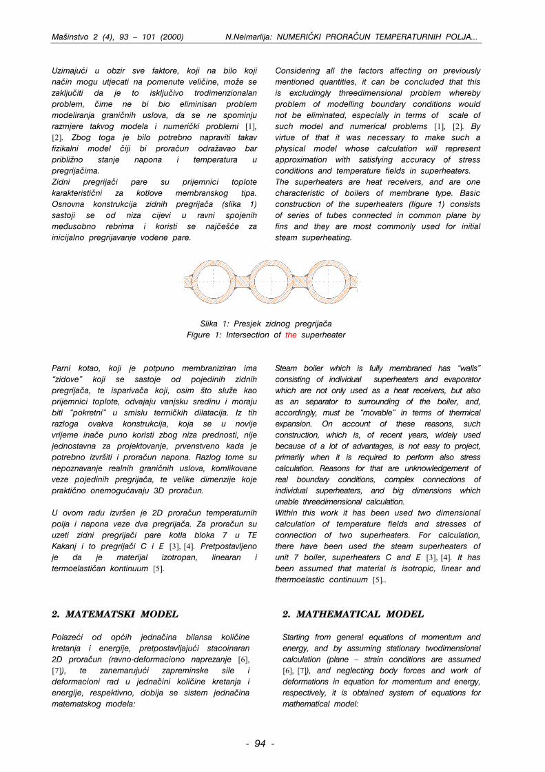
Uzimajui u obzir sve faktore, koji na bilo koji na~in mogu utjecati na pomenute veli~ine, mo`e se zaklju~iti da je to isklju~ivo trodimenzionalan problem, ~ime ne bi bio eliminisan problem modeliranja grani~nih uslova, da se ne spominju razmjere takvog modela i numeri~ki problemi [1], [2]. Zbog toga je bilo potrebno napraviti takav fizikalni model ~iji bi prora~un odra`avao bar pribli`no stanje napona i temperatura u pregrija~ima. Zidni pregrija~i pare su prijemnici toplote karakteristi~ni za kotlove membranskog tipa. Osnovna konstrukcija zidnih pregrija~a (slika 1) sastoji se od niza cijevi u ravni spojenih me|usobno rebrima i koristi se naj~ee za inicijalno pregrijavanje vodene pare.
Considering all the factors affecting on previously mentioned quantities, it can be concluded that this is excludingly threedimensional problem whereby problem of modelling boundary conditions would not be eliminated, especially in terms of scale of such model and numerical problems [1], [2]. By virtue of that it was necessary to make such a physical model whose calculation will represent approximation with satisfying accuracy of stress conditions and temperature fields in superheaters. The superheaters are heat receivers, and are one characteristic of boilers of membrane type. Basic construction of the superheaters (figure 1) consists of series of tubes connected in common plane by fins and they are most commonly used for initial steam superheating.
Slika 1: Presjek zidnog pregrija~a
Figure 1: Intersection of the superheater Parni kotao, koji je potpuno membraniziran ima “zidove” koji se sastoje od pojedinih zidnih pregrija~a, te ispariva~a koji, osim to slu`e kao prijemnici toplote, odvajaju vanjsku sredinu i moraju biti “pokretni” u smislu termi~kih dilatacija. Iz tih razloga ovakva konstrukcija, koja se u novije vrijeme ina~e puno koristi zbog niza prednosti, nije jednostavna za projektovanje, prvenstveno kada je potrebno izvriti i prora~un napona. Razlog tome su nepoznavanje realnih grani~nih uslova, komlikovane veze pojedinih pregrija~a, te velike dimenzije koje prakti~no onemoguavaju 3D prora~un. U ovom radu izvren je 2D prora~un temperaturnih polja i napona veze dva pregrija~a. Za prora~un su uzeti zidni pregrija~i pare kotla bloka 7 u TE Kakanj i to pregrija~i C i E [3], [4]. Pretpostavljeno je da je materijal izotropan, linearan i termoelasti~an kontinuum [5].
Steam boiler which is fully membraned has “walls” consisting of individual superheaters and evaporator which are not only used as a heat receivers, but also as an separator to surrounding of the boiler, and, accordingly, must be “movable” in terms of thermical expansion. On account of these reasons, such construction, which is, of recent years, widely used because of a lot of advantages, is not easy to project, primarily when it is required to perform also stress calculation. Reasons for that are unknowledgement of real boundary conditions, complex connections of individual superheaters, and big dimensions which unable threedimensional calculation. Within this work it has been used two dimensional calculation of temperature fields and stresses of connection of two superheaters. For calculation, there have been used the steam superheaters of unit 7 boiler, superheaters C and E [3], [4]. It has been assumed that material is isotropic, linear and thermoelastic continuum [5]..
2. MATEMATSKI MODEL Polazei od opih jedna~ina bilansa koli~ine kretanja i energije, pretpostavljajui stacoinaran 2D prora~un (ravno-deformaciono naprezanje [6], [7]), te zanemarujui zapreminske sile i deformacioni rad u jedna~ini koli~ine kretanja i energije, respektivno, dobija se sistem jedna~ina matematskog modela:
2. MATHEMATICAL MODEL Starting from general equations of momentum and energy, and by assuming stationary twodimensional calculation (plane – strain conditions are assumed [6], [7]), and neglecting body forces and work of deformations in equation for momentum and energy, respectively, it is obtained system of equations for mathematical model:
- 94 -
Mainstvo 2 (4), 93 – 101 (2000) N.Neimarlija: NUMERI^KI PRORA^UN TEMPERATURNIH POLJA...
032 =
∂∂
+∂∂
µ+
∆α−
∂∂
+∂∂
λ+∂∂
µ∫S
yx dSnxv
yunTK
yv
xu
xu
, (1)
∫ =
∆α−
∂∂
+∂∂
λ+∂∂
µ+
∂∂
+∂∂
µS
032 dSnTKyv
xu
yvn
yu
xv
yx , (2)
0)( =∂∂
+∂∂
∫ dSnyTkn
xTk
Syx . (3)
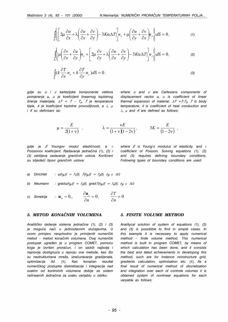
gdje su u i v kartezijske komponente vektora pomjeranja u, α je koeficijent linearnog toplotnog irenja materijala, ∆T = T – To, T je temperatura tijela, k je koeficijent toplotne provodljivosti, a λ, µ i K su definisani sa:
where u and v are Cartesians components of displacement vector u, α is coefficient of linear thermal expansion of material, ∆T =T-T0, T is body temperature, k is coefficient of heat conduction and λ, µ and K are defined as follows:
( )ν+=12E
µ , ( )( )ν−ν+ν
=211
Eλ , ( )ν−
=21EK3 ,
gdje je E Youngov modul elasti~nosti, a ν Poissonov koeficijent. Rjeavanje jedna~ina (1), (2) i (3) zahtijeva zadavanje grani~nih uslova. Korieni su slijedei tipovi grani~nih uslova:
where E is Young’s modulus of elasticity, and ν coefficient of Poisson. Solving equations (1), (2) and (3) requires defining boundary conditions. Following types of boundary conditions are used:
a) Dirichlet : u(rB,t) = f1(t), T(rB,t) = f2(t), rB ∈ δΩ b) Neumann : gradu(rB,t) = f3(t), gradT(rB,t) = f4(t), rB ∈ δΩ
c) Simetrija : ,u , n 0= 0=∂∂ntu , 0=
∂∂nT
3. METOD KONA^NIH VOLUMENA Analiti~ko rjeenje sistema jedna~ina (1), (2) i (3) je mogue nai u jednostavnim slu~ajevima. U ovom primjeru neophodno je primijeniti numeri~ki metod – metod kona~nih volumena. Ovaj numeri~ki postupak ugra|en je u program COMET, pomou koga je izvren prora~un, i on sadr`i najbolja i najnovija dostignua u razvoju ove metode, kao to su nestrukturirana mre`a, izra~unavanje gradijenata, optimizacija itd. [8]. Kao kona~an rezultat numeri~kog postupka diskretizacije i integracije nad svakim od kontrolnih volumena dobije se sistem nelinearnih jedna~ina za svaku varijablu u obliku:
3. FINITE VOLUME METHOD Analitycal solution of system of equations (1), (2) and (3) is possibble to find in simple cases. In this example it is necessary to apply numerical method – finite volume method. This numerical method is built in program COMET, by means of which calculation has been done, and it consists the best and latest achievements in developing this method, such are for instance nonstructure grid, gradients calculation, optimisation etc. [8]. As a final result of numerical method of discretization and integration over each of controle volumes it is obtained system of nonlinear equations for each varyable as follows:
- 95 -
Mainstvo 2 (4), 93 – 101 (2000) N.Neimarlija: NUMERI^KI PRORA^UN TEMPERATURNIH POLJA...
a (4) φ=
φφ =φ−φ ∑ ban
jPjjPoo
1
Ovdje je n broj stranica posmatranog kontrolnog volumena. Koeficijenti a i izvor b definisani su u referencama [8] i [9]. Koriten je princip tzv. “odvojenog” rjeavanja linearizovanog sistema jedna~ina. Nakon primjene po~etnih i grani~nih uslova dobije se sistem linearnih algebarskih jedna~ina: (5) b=φA Za rjeavanje sistema jedna~ina (5) koriten je algoritam poznat pod nazivom Incomplete Cholesky Preconditioned Conjugate G adient metod (ICCG). Zbog stacionarnosti i stoga elipti~ne prirode jedna~ina matematskog modela, te zna~ajnog broja kontrolnih volumena, neophodno je bilo koristiti multigrid tehniku ubrzavanja konvergencije [9]. Generisane su tri grube mre`e.
r
Label n is here a number of surfaces of considered control volume. Coefficients a and the source b have been defined within referencies [8] and [9]. There has been used a principle of so-called “segregated” solution of linearized system of equations. After applying initial and boundary conditions it is obtained system of linear algebraic equations as follows: (5) b=φA There was used algorithm named Incomplete Cholesky Preconditioned Conjugate Gradient method (ICCG) for solving equations (5). By virtue of steadyness and, therefore, elliptical nature of equations of mathematical model, and because of considerable number of controle volume, it is necessary to use multigrid technic of accelerating convergency [9]. There have been generated three coarse grids.
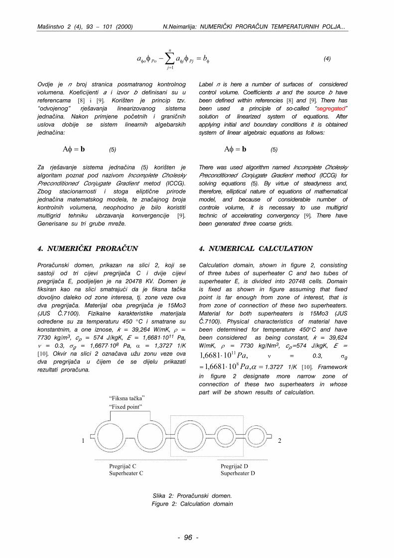
4. NUMERI^KI PRORA^UN Prora~unski domen, prikazan na slici 2, koji se sastoji od tri cijevi pregrija~a C i dvije cijevi pregrija~a E, podijeljen je na 20478 KV. Domen je fiksiran kao na slici smatrajui da je fiksna ta~ka dovoljno daleko od zone interesa, tj. zone veze ova dva pregrija~a. Materijal oba pregrija~a je 15Mo3 (JUS ^.7100). Fizikalne karakteristike materijala odre|ene su za temperaturu 450 °C i smatrane su konstantnim, a one iznose, k = 39,264 W/mK, ρ = 7730 kg/m3, cp = 574 J/kgK, E = 1,6681⋅1011 Pa, ν = 0.3, σg = 1,6677⋅108 Pa, α = 1,3727 1/K [10]. Okvir na slici 2 ozna~ava u`u zonu veze ova dva pregrija~a u ~ijem e se dijelu prikazati rezultati prora~una.
4. NUMERICAL CALCULATION Calculation domain, shown in figure 2, consisting of three tubes of superheater C and two tubes of superheater E, is divided into 20748 cells. Domain is fixed as shown in figure assuming that fixed point is far enough from zone of interest, that is from zone of connection of these two superheaters. Material for both superheaters is 15Mo3 (JUS ^.7100). Physical characteristics of material have been determined for temperature 450°C and have been considered as being constant, k = 39,624 W/mK, ρ = 7730 kg/Nm3, cp=574 J/kgK, E =
ν = 0.3, σ,106681,1 11Pa⋅⋅ ,106681, 8Pa
g
=1 1.3727 1/K [10]. Framework in figure 2 designate more narrow zone of connection of these two superheaters in whose part will be shown results of calculation.
=α
“Fiksna ta~ka”
“Fixed point”
2
1
Pregrija~ C Superheater C
Pregrija~ D Superheater D
Slika 2: Prora~unski domen. Figure 2: Calculation domain
- 96 -
Mainstvo 2 (4), 93 – 101 (2000) N.Neimarlija: NUMERI^KI PRORA^UN TEMPERATURNIH POLJA...
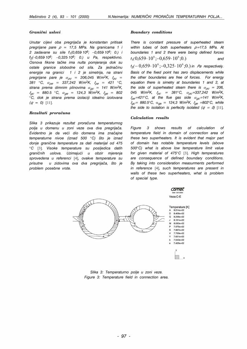
Grani~ni uslovi Unutar cijevi oba pregrija~a je konstantan pritisak pregrijane pare p = 17,5 MPa. Na granicama 1 i 2 zadavane su sile f1(0,659⋅106; −0,659⋅106; 0.) i f2(−0,659⋅106; −0,325⋅106; 0.) u Pa, respektivno. Osnova fiksne ta~ke ima nulta pomjeranja dok su ostale granice slobodne od sila. Za jedna~inu energije na granici 1 i 2 je simetrija, na strani pregrijane pare je αpc = 206,045 W/m2K, tpc = 381 °C, αpe = 337,242 W/m2K, tpe = 421 °C, strana prema dimnim plinovima αgc = 141 W/m2K, tgc = 880.5 °C, αge = 124,3 W/m2K, tge = 802 °C, dok je strana prema izolaciji idealno izolovana (q = 0) [11]. Rezultati prora~una Slika 3 prikazuje rezultat prora~una temperaturnog polja u domenu u zoni veze ova dva pregrija~a. Evidentno je da vei dio domena ima zna~ajne temperaturne nivoe (iznad 500 °C) to je iznad donje grani~ne temperature za dati materijal od 475 °C [3]. Visoke temperature su posljedica datih grani~nih uslova. Uzimajui u obzir mjerenja sprovedena u referenci [4], ovakve temperature su prisutne u zidovima ova dva pregrija~a, to je problem posebne vrste.
Boundary conditions There is constant pressure of superheated steam within tubes of both superheaters p=17,5 MPa. At boundaries 1 and 2 there were being defined forces
f1(0 and
f
.)0;10659,0;10659, 66 ⋅−⋅0;10325,0;10659,0 66 ⋅−⋅−2( in Pa respectively.
Basis of the fixed point has zero displacements while the other boundaries are free of forces. For energy equation there is simetry at boundaries 1 and 2, at the side of superheated steam there is α
.)
pc = 206, 045 W/m2K, tpc = 381°C, αpc=337,242 W/m2K, tpe=421°C, at the flue gas side αgc=141 W/m2K, tgc= 880.5°C, αge = 124,3 W/m2K, tge =802°C, while the side to isolation is perfectly isolated (q = 0) [11]. Calculation results Figure 3 shows results of calculation of temperature field in domain of connection area of these two superheaters. It is evident that major part of domain has notable temperature levels (above 500°C) what is above low temperature limit value for given material of 475°C [3]. High temperatures are consequence of defined boundary conditions. By taking into consideration measurments performed in reference [4], such temperatures are present in walls of these two superheaters, what is problem of special type.
Slika 3: Temperaturno polje u zoni veze. Figure 3: Temperature field in connection area.
- 97 -
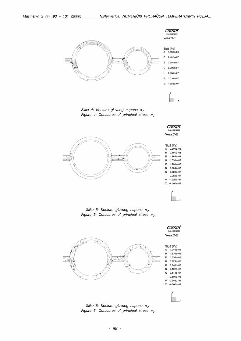
Mainstvo 2 (4), 93 – 101 (2000) N.Neimarlija: NUMERI^KI PRORA^UN TEMPERATURNIH POLJA...
Slika 4: Konture glavnog napona σ1.
Figure 4: Contoures of principal stress σ1
Slika 5: Konture glavnog napona σ2.
Figure 5: Contoures of principal stress σ2
Slika 6: Konture glavnog napona σ3. Figure 6: Contoures of principal stress σ3
- 98 -
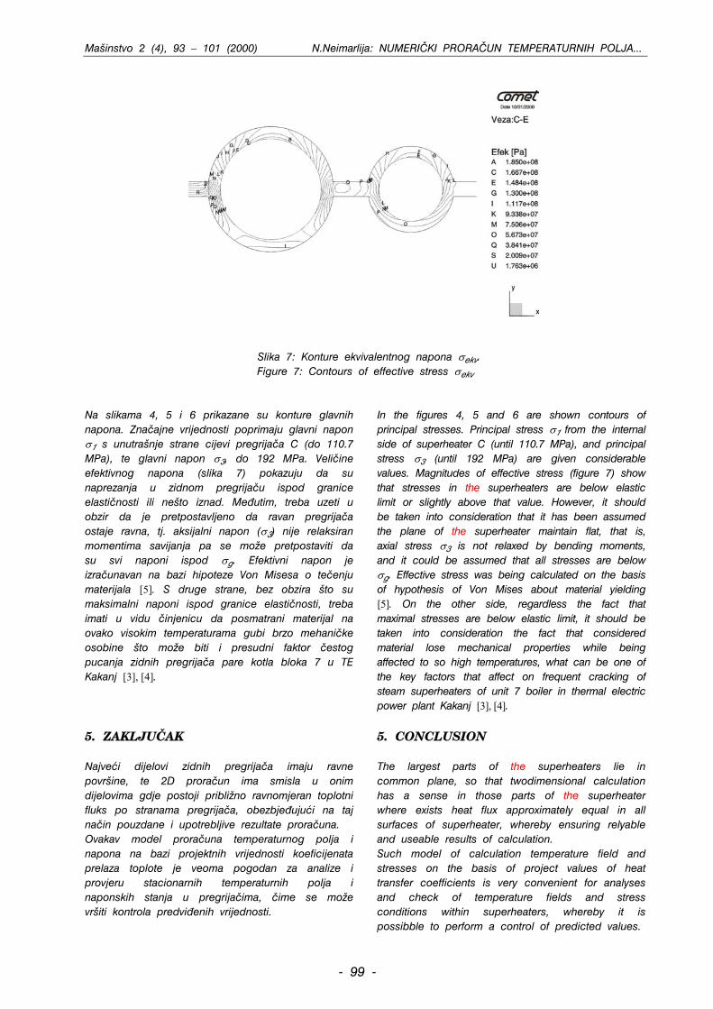
Mainstvo 2 (4), 93 – 101 (2000) N.Neimarlija: NUMERI^KI PRORA^UN TEMPERATURNIH POLJA...
Slika 7: Konture ekvivalentnog napona σekv.
Figure 7: Contours of effective stress σekv Na slikama 4, 5 i 6 prikazane su konture glavnih napona. Zna~ajne vrijednosti poprimaju glavni napon σ1 s unutranje strane cijevi pregrija~a C (do 110.7 MPa), te glavni napon σ3, do 192 MPa. Veli~ine efektivnog napona (slika 7) pokazuju da su naprezanja u zidnom pregrija~u ispod granice elasti~nosti ili neto iznad. Me|utim, treba uzeti u obzir da je pretpostavljeno da ravan pregrija~a ostaje ravna, tj. aksijalni napon (σ3) nije relaksiran momentima savijanja pa se mo`e pretpostaviti da su svi naponi ispod σg. Efektivni napon je izra~unavan na bazi hipoteze Von Misesa o te~enju materijala [5]. S druge strane, bez obzira to su maksimalni naponi ispod granice elasti~nosti, treba imati u vidu ~injenicu da posmatrani materijal na ovako visokim temperaturama gubi brzo mehani~ke osobine to mo`e biti i presudni faktor ~estog pucanja zidnih pregrija~a pare kotla bloka 7 u TE Kakanj [3], [4].
In the figures 4, 5 and 6 are shown contours of principal stresses. Principal stress σ1 from the internal side of superheater C (until 110.7 MPa), and principal stress σ3 (until 192 MPa) are given considerable values. Magnitudes of effective stress (figure 7) show that stresses in the superheaters are below elastic limit or slightly above that value. However, it should be taken into consideration that it has been assumed the plane of the superheater maintain flat, that is, axial stress σ3 is not relaxed by bending moments, and it could be assumed that all stresses are below σg. Effective stress was being calculated on the basis of hypothesis of Von Mises about material yielding [5]. On the other side, regardless the fact that maximal stresses are below elastic limit, it should be taken into consideration the fact that considered material lose mechanical properties while being affected to so high temperatures, what can be one of the key factors that affect on frequent cracking of steam superheaters of unit 7 boiler in thermal electric power plant Kakanj [3], [4].
5. ZAKLJU^AK Najvei dijelovi zidnih pregrija~a imaju ravne povrine, te 2D prora~un ima smisla u onim dijelovima gdje postoji pribli`no ravnomjeran toplotni fluks po stranama pregrija~a, obezbje|ujui na taj na~in pouzdane i upotrebljive rezultate prora~una. Ovakav model prora~una temperaturnog polja i napona na bazi projektnih vrijednosti koeficijenata prelaza toplote je veoma pogodan za analize i provjeru stacionarnih temperaturnih polja i naponskih stanja u pregrija~ima, ~ime se mo`e vriti kontrola predvi|enih vrijednosti.
5. CONCLUSION The largest parts of the superheaters lie in common plane, so that twodimensional calculation has a sense in those parts of the superheater where exists heat flux approximately equal in all surfaces of superheater, whereby ensuring relyable and useable results of calculation. Such model of calculation temperature field and stresses on the basis of project values of heat transfer coefficients is very convenient for analyses and check of temperature fields and stress conditions within superheaters, whereby it is possibble to perform a control of predicted values.
- 99 -
Mainstvo 2 (4), 93 – 101 (2000) N.Neimarlija: NUMERI^KI PRORA^UN TEMPERATURNIH POLJA...
Ta~nost primijenjenog numeri~kog postupka iroko je testirana u referenci [12]. Upotrebljivost dobijenih vrijednosti zavisi isklju~ivo od realnosti egzistencije usvojenih grani~nih uslova, to se u ovom slu~aju `eljelo osigurati koritenjem projektnih podataka.
Accuracy of applied numerical method has been widely tested in reference [12]. Useability of obtained values depends exclusively upon presence of adopted boundary conditions, so there has been an intention to ensure this useability by using project data.
6. LITERATURA - REFERENCES [1] C. BRATIANU, L. COJOCIA, “Finite element
analysis of an inverse transient heat conduction problem”, in: S. N. Atluri and P. E. O’Donoghue (Eds), Modelling and Simulation Based Engineering, Vol II, Tech. Science Press, Palmdale, CA, 1998., 1924 – 1931.
[2] L. COJOCIA, “Analiza cu elemente finite a
tensiunilor termice si mecanice din subansamblele generatoarelor de abur in regim tranzitoriu”, teza de doctorat, Universitatea politehnica din Bucuresti, Facultatea de inginerie mecanica, Bucuresti, 1997.
[3] X X X , “Analiza ostvarivanja projektnih
parametara i uticaj utvr|enih realnih radnih parametara grejnih povrina kotla 230 MW TE KAKANJ na eksploatacioni vijek postrojenja”, Institut za nuklearne nauke “Boris Kidri~”, Beograd – Vin~a, 1988.
[4] X X X , “Utvr|ivanje realnih radnih uslova i
njihov uticaj na radni vijek metala pregrija~kog sistema a posebno na radni vijek membranskih zidova drugog promajnog cuga kotla 230 MW TE KAKANJ”, Institut za nuklearne nauke “Boris Kidri~”, Beograd – Vin~a, 1989.
[5] I. DEMIRD@I], “Mehanika kontinuuma”, Mainski fakultet Sarajevo, 1998.
[6] B. A. BOLEY I J. H. WEINER, “Theory of
thermal stresses”, John Wiley & Sons, Inc., New York – London, second printing, january, 1962.
[7] S. TIMOSHENKO, J. N. GOODIER, “Teorija
elasti~nosti”, drugo izdanje, McGraw-Hill, 1951., (Gra|evinska knjiga, Beograd, 1962.)
[8] COMET User Manual, ICCM, Hamburg, 1998. [9] I. DEMIRD@I], A. IVANKOVI], SA-1996,
“Lecture notes for the course Finite Volume Stress Analysis”, Imperial College London, 1998.
[10] X X X , “Kotlovske cijevi”, Priru~nik, @eljezara
Sisak, 1969. [11] X X X , “Projekat kotla bloka 7 TE Kakanj”,
SES Tlma~e, Brno, 1980. [12] N. NEIMARLIJA, “Analiza temperaturnih polja i
termalnih napona na karakteristi~nim vezama dva ili vie zidnih pregrija~a pare u kotlovima membranskog tipa”, magistarski rad, Sarajevo, 1999.
Oznake A − matrica koeficijenata sistema algebarskih jedna~ina a − koeficijent u jedna~ini (4) b − izvor zavisne varijable u posmatranom ~voru b − vektor kolona sistema algebarskih jedna~ina (5) c − specifi~na toplota E − Jangov modul elasti~nosti f − funkcija vremena k − koeficijent toplotne provodljivosti izotropnog tijela K − zapreminski modul elasti~nosti n − vektor normale nx, ny − kartezijske komponente vektora normale n p − pritisak
Labels A – matrix of coefficients of algebraic equations system a - coefficients in equation (4) b - source of dependent variable in considered node b - vector of columns of algebraic system equation c - specific heat E – Young’s modulus of elasticity f - time function k - coefficient of heat conductivity of considered body K - volume modulus of elasticity n - unit surface vector nx, ny – cartesian components of vector n p - pressure
- 100 -
Mainstvo 2 (4), 93 – 101 (2000) N.Neimarlija: NUMERI^KI PRORA^UN TEMPERATURNIH POLJA...
q − toplotni fuks r − vektor polo`aja S − povrina T − apsolutna temperatura tijela To − referentna apsolutna temperatura tijela t − vrijeme, temperatura u − vektor pomjeranja u, v − komponente pomjeranja u kartezijevom koordinatnom sistemu x, y − koordinate vektora polo`aja α − koeficijent linearnog toplotnog irenja, koeficijent prelaza toplote δΩ − dio granice domena λ − Laméova konstanta µ − Laméova konstanta ν − Poassonov koeficijent ρ − specifi~na gustoa σ − normalni napon φ − zavisna varijabla φ − vektor kolona zavisne varijable φ, jedna~ina (5)
q - heat flux r - position vector S - surface T - absolute temperature of the body T0 – referent absolute temperature of the body t - time, temperature u - displacement vector u, v – components of displacement in Cartesian coordinate system x, y - coordinates of position vector α - coefficient of linear thermal expansion, coefficient of heat transfer δΩ - part of solution domain boundaries λ - Lame’s constant µ - Lame’s constant ν - Poisson’s coefficient ρ - specific density σ - normal stress φ - dependent variable φ - vector of column of dependent variable φ, equation (5)
Indeksi
B − grani~ni ~vor P − prora~unski ~vor c − pregrija~ C e − pregrija~ E ekv − ekvivalentno g − gas, granica elasti~nosti j − indeks susjednog ~vora, odnosno susjedne stranice n − normalno na povrinu o − posmatrani prora~unski ~vor p − strana pare t − tangencijalni pravac x, y − kartezijevi koordinatni pravci φ − zavisna varijabla
Indexes B – boundary node P - calculation node c - superheater C e - superheater E ekv – equivalent g - gas, elastic limit j - index of adjacent node, that is adjacent surface n - perpendicular to surface o - considered calculation node p - steam side t - tangential direction x, y – cartesian coordinate directions φ - dependent variable
- 101 -
Mainstvo 2(4), 103 – 113, (2000) B.Mijovi,...: NUMERI^KA SIMULACIJA PROCESA OBRADE...
NUMERI^KA SIMULACIJA PROCESA OBRADA LIMA PROFILIRANIM VALJANJEM
Prof. Dr. Budimir Mijovi, Tekstilno-tehnoloki fakultet, Sveu~ilita u Zagrebu Ibriim Herac, Dipl. Ing., WIBA – PARA, Voecklamarkt Austria
D REZIME
Prednosti simulacije obrade lima pomou komercijalnih MKE programa posse ova metoda primijeni na realne procese obrade lima koji uklju~uju svese moraju diskretizirati s velikim brojem elemenata i ~vorova. Sve ovpripremu koja zahtijeva veliko ulaganje in`enjerskog vremena. Ovo se nejer i druge metode ra~unanja imaju odre|ene nedostatke. Me|utim, vrijemmo`e se poveati do tih razmjera da su ra~unari kao to je PC neprrezultate tek nakon dugog vremena ra~unanja. U radu je ukazano npojavljuju prilikom prora~una naprezanja i deformacija u procesu obrade lobjanjeni su neki ~esto upotrebljavani na~ini prevladavanja ovih problemna~in je upotreba ra~unarskih programa specijaliziranih za prora~une u odrugi je upotreba klasi~nih MKE programa.
Klju~ne rije~i: Profilirano valjanje, metoda kona~nih elemenata, numeri~
NUMERIC SIMULATION OF ROLL-FOF SHEET METAL
Budimir Mijovi, PhD., professor, Faculty of Textile TechnolZagreb, Zagreb, Croatia Ibriim Herac, B.Sc, WIBA – PARA, Voecklamarkt, Austria
SUMMARY
The advantage of simulation of metal sheet forming by commercial Minteresting if this method is applied to real processes of metal sheet formlinearity and models which should be discretised with a large number of requires very extensive preparation which requires big investment of engconsidered to be a drawback since other methods of calculations alsHowever time invested in the calculation itself can be increased until such as PC are impractical and yields corresponding results only calculation. Certain problems have been pointed to in the work whicdeformation calculation roll-forming of metal sheet and some frequentlythese problems in current practice have been explained. The first way isspecialized for calculations in this kind of forming and second is use of
Key words: roll-forming, method of final elements, numeric experiment
- 103 -
STRU^NI RA
taju manje interesantne ako nelinearnosti i modele koji o zahtijeva veoma obimnu mo`e smatrati nedostatkom e utroeno u sam prora~un akti~ni i daju odgovarajue a neke probleme koji se ima profiliranim valjanjem te a u dananjoj praksi. Prvi voj vrsti procesa obrade, a
ki eksperiment
ORMING
ogy, University of
PROFESSIONAL PAPERKE program become less ing which includes all non-elements and knots. All this ineering time. This can be o have certain drawbacks. such extent that computers after long time spent on h occur during strain and used ways of overcoming use of computer programs classic MKE programs.
Mainstvo 2(4), 103 – 113, (2000) B.Mijovi,...: NUMERI^KA SIMULACIJA PROCESA OBRADE...
1. UVOD Zbog velike produktivnosti, profilirano valjanje danas se sve vie koristi u obradi lima.Veliki broj profila s veoma razli~itim popre~nim presjecima izra|uje se kako u vruem tako i u hladnom stanju [1,2]. Naprezanja i deformacije koji se javljaju u obradi lima mogu dovesti do velikih iskrivljenja profila. Naro~ito veliki utjecaj na uzdu`na iskrivljenja profila imaju uzdu`ne deformacije koje ne smiju znatnije prekora~iti granicu elasti~nosti materijala. Ova iskrivljenja ~ine nerijetko profil neupotrebljivim, a stroj kojim se proizvodi profil mora se korigirati. ^esto je neophodno izmijeniti cijeli komplet skupih valjaka, a pri tome i dobar dio konstrukcije stroja. Da bi se izbjegle nepo`eljne promjene na stroju potrebno je prije po~etka izrade stroja unaprijed izra~unati naprezanja i deformacije u procesu obrade lima [3]. Zna~aj vremena utroenog u sam prora~un problema profiliranog valjanja u tehni~koj se praksi mo`e umanjiti na vie na~ina [4,5,6]. Jedan je poveanje brzine ra~unara i njegovih komponeneta koje utje~u na brzinu prora~una i brzinu prenosa podataka. Za jednostavnije i br`e nala`enje forme i oblika alata za valjanje koriste se razni ra~unarski sistemi i odgovarajui programski paketi [7]. Ovakvi tzv. tehnoloki procesori omoguavaju ve u fazi konstrukcije ispitivanje konfiguracije alata kroz numeri~ke eksperimente [8,9,10,11]. Izlazni podaci mogu se dobiti tabelarno, dijagramski i grafi~ki. Na svakom grafi~kom prikazu mo`e se u bojama prikazati stupnjevano intenzitet odre|ene izlazne veli~ine.
1. INTRODUCTION Due to large productivity, roll-forming profiling is currently used more and more in metal sheet forming. Large number of profiles with very diversified diagonal section is formed both in hot and cold condition [1,2]. Strain and deformation which occur in the metal sheet forming may cause large profile deformation. Diagonal deformations which should not more considerable pass the limit of material elasticity have special influence on longitudinal profile deformations. These deformations make the profile inapplicable and a machine producing this profile should be corrected. It is very often essential to change entire complete of expensive rollers and thus also a good part of machine construction. In order to avoid unwanted changes on the machine it is necessary, before beginning of work of machine to calculate in advance strains and deformations in the process of metal sheet roll-forming. [3]. Importance of time spent in calculation of problem of profile roll-forming in technical practice can be reduced in several ways [4,5,6]. One of them is increase of computer velocity and its components influencing speed of calculation and speed of data transfer. For more simple and quicker finding of the form and shape of the rolling tools, various computer systems and corresponding program packages are used [7]. Such so called technological processors enable already in the phase of construction testing of tool configuration through numeric experiments. [8,9,10,11]. Outgoing data can be obtained tabular, diagram and graphically. The intensity of certain outgoing sizes can be presented gradedly in colors in each graphic survey.
2. ANALIZA PROCESA OBRADE LIMA Naro~ito veliki utjecaj na uzdu`na iskrivljenja profila imaju uzdu`ne deformacije koje ne smiju znatnije prekora~iti granicu elasti~nosti materijala. Ovaj primjer na kome je vrena optimalizacija napravljen je na PC ra~unaru s Pentium III procesorom, 256 MB RAM 100 MHz, SCSI hard diskom, s brzinom prenosa podataka od 40 MB/s. U ovom trenutku je ova konfiguracija ra~unara veoma napredna i dalje poveanje brzine mogue je postii uz upotrebu vie procesora. Me|utim neki komercijalni MKE programi ne podr`avaju vie mikroprocesora. Primjer takvog programa je upotrebljeni ANSYS 5.5.2 koji u stvari podr`ava rad samo dva procesora, ali samo jedan od njih mo`e raditi punom snagom za izvo|enje ra~unskih operacija. Napravljeni primjer izveden je upotrebom Shell elemenata koji nedvojbeno daju rezultate uz kratko ra~unarsko vrijeme.
2. ANALYSIS OF METAL SHEET ROLL-FORMING The longitudinal deformations which could not considerably exceed limit of material elasticity have specially considerable influence on longitudinal exertions. This example on which optimization have been made was effected on PC computer with Pentium III processor, 256 MB RAM 100 MHz, SCSI hard disc, with velocity of data transfer of 40 MB/s. At the moment this computer configuration is very advanced and further increase of velocity is possible with use of more processors. However some commercial MKE programs do not support more microprocessors. An example of such program is used ANSYS 5.5.2 which actually support a work of only two processors, but only one of them can operate at fool speed for performance of computational operations. The made example was made by use of Shell elements which undoubtedly yield results with short computational time.
- 104 -
Mainstvo 2(4), 103 – 113, (2000) B.Mijovi,...: NUMERI^KA SIMULACIJA PROCESA OBRADE...
Pri izboru Shell elemenata ne dobivaju se podaci o preciznoj raspodjeli naprezanja i deformacija po debljini lima. Medutim kod obrade lima profiliranim valjanjem takvi su podaci u veini slu~ajeva neinteresantni pa je preporu~ljivo ovakve elemente gotovo uvijek primjenjivati. Svaki deformirani model u odre|enom vremenskom trenutku mo`e biti snimljen kao grafi~ka mapa, npr. bit mapa kao u naem slu~aju, a onda se vei broj bit mapa mo`e dalje upotrijebiti za izradu simulacije procesa obrade kako je u~injeno u prilo`enoj simulaciji. Za prora~un naprezanja i deformacija kod profiliranog valjanja koriste se razni ra~unarski sistemi i odgovarajui programski paketi. Kod analiziraog modela uzeta je debljina lima 0.8mm.
With a process of choosing the Shell elements no data are obtained on precise distribution and deformation byte sheet metal thickness. However in the process of sheet metal roll-forming such data are in the majority of cases uninteresting so it is recommendable to use such elements almost always. Each deformed model at certain moment can be recorded as graphic map, e.g. bit map in our case and then larger number of bit maps can be further used for making simulation process of forming as it has been done in the attached simulation. Various computer systems and corresponding program packages are being used for calculation of strain and deformation profile roll-forming. In the analysed model sheet metal thickness of 0.8 mm has been used.
2.1. Metoda kona~nih elemenata Danas se pored analiti~kih programa za prora~un koristi i metoda kona~nih elemenata uz primjenu ra~unara veih kapaciteta memorije i brzine ra~unanja. Kod svih dosada poznatih programa nu`no je uklju~ivanje gotovo svih nelineariteta me|u kojima prvenstveno geometrijski, nelinearnost materijala i strukturni. Osim toga moraju se uvesti tzv. kontakt ili ”Gap” elementi na mjestu kontakta lima i valjaka. Sve ovo zahtijeva nelinearnu stati~ku analizu gdje je temeljna jednad`ba za stati~ku strukturnu mehaniku
[ ] ( ) tFuK =∗ (1)
matrica krutosti [K] je ovisna o pomaku, gdje je
[ ] (2) ( )[ uKK = ] U ovom slu~aju govori se o nelinearnom ponaanju. Da bi se ovakav zadatak rijeio, nu`an je iterativni postupak. Kod iterativnog postupka
polazi se od jednog izlaznog stanja [K 0 ] i
odre|uje se jedno rjeenje u. S ovim rjeenjem
se odre|uje jedna prilago|ena matrica [K i ] i time
se dobije (i+1) rjeenje. Iterativni postupak se ponavlja tako dugo dok se razlika izme|u dvije iteracije ne pribli`i zadovoljavajuoj vrijednosti. Ovakva nelinearna analiza svojstvena je gotovo svim klasi~nim MKE programima. Nelinearnu analizu i kontaktne elemente posjeduju svi novi MKE programski paketi. Za nelinerni materijal uzima se veza izme|u naprezanja i deformacije
[ ]elD εσ = (3)
2.1. Method of final elements Besides the analytical program also a method of final elements is used nowadays with application of analytical programs for profit calculation and method of final elements within application of computers of bigger capacities of the memory and calculation velocity. With all up to now known programs it is necessary for include almost all non-linearity among which firstly geometrical, nonlinearly of material and structural. Besides, so called contacts or "Gap’’ elements should be introduced on the place of contact between sheet metal and rollers. All this require nonlinear statistical analysis where basic equitation for statistical structural mechanic
[ ] ( ) tFuK =∗ (1)
rigidity matrix [K] is dependent on the shift, where
[ ] (2) ( )[ uKK = ] In this case we talk of non-linear behavior. In order to solve this task, iterative procedure is necessary. In iterative procedure we start from one
outgoing conditions [K 0 ] and one solution is
determined u. With this solution one adapted
matrix is determined [K i ] and thus this solution is
obtained (i+1)Iterative procedure is repeated so long until difference between two iterations come close to satisfactory value. Such nonlinear analysis is typical of almost all classic MKE programs. All new MKE program packages possesses such nonlinear analysis. Relation between strain and deformation is taken for non-linear material.
[ ]elD εσ = (3)
- 105 -
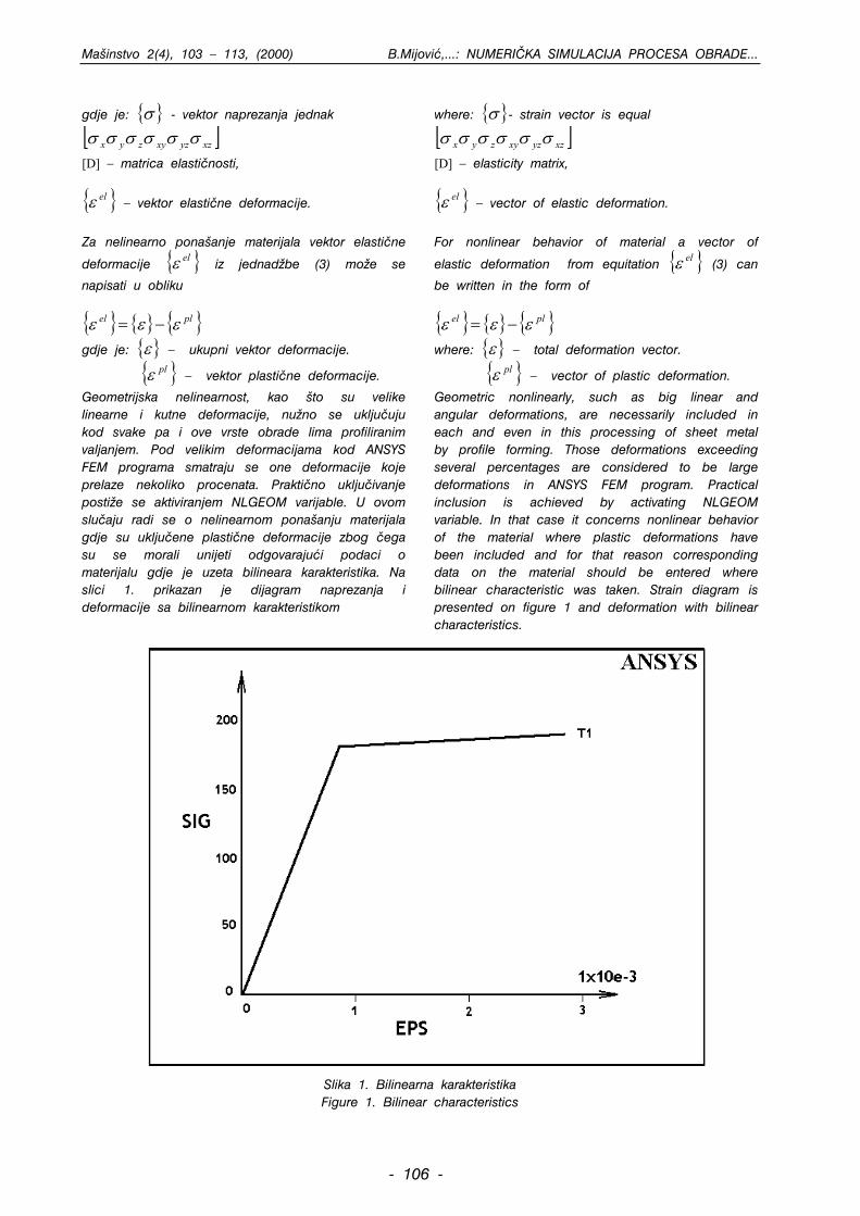
Mainstvo 2(4), 103 – 113, (2000) B.Mijovi,...: NUMERI^KA SIMULACIJA PROCESA OBRADE...
gdje je: - vektor naprezanja jednak σ[ ]xzyzxyzyx σσσσσσ
[D] – matrica elasti~nosti,
elε – vektor elasti~ne deformacije.
Za nelinearno ponaanje materijala vektor elasti~ne
deformacije elε iz jednad`be (3) mo`e se
napisati u obliku
plel εεε −=
gdje je: – ukupni vektor deformacije. ε plε – vektor plasti~ne deformacije.
Geometrijska nelinearnost, kao to su velike linearne i kutne deformacije, nu`no se uklju~uju kod svake pa i ove vrste obrade lima profiliranim valjanjem. Pod velikim deformacijama kod ANSYS FEM programa smatraju se one deformacije koje prelaze nekoliko procenata. Prakti~no uklju~ivanje posti`e se aktiviranjem NLGEOM varijable. U ovom slu~aju radi se o nelinearnom ponaanju materijala gdje su uklju~ene plasti~ne deformacije zbog ~ega su se morali unijeti odgovarajui podaci o materijalu gdje je uzeta bilineara karakteristika. Na slici 1. prikazan je dijagram naprezanja i deformacije sa bilinearnom karakteristikom
where: - strain vector is equal σ[ ]xzyzxyzyx σσσσσσ
[D] – elasticity matrix,
elε – vector of elastic deformation.
For nonlinear behavior of material a ector of
elastic deformation from equitation
v
elε (3) can
be written in the form of
plel εεε −=
where: – total deformation vector. ε plε – vector of plastic deformation.
Geometric nonlinearly, such as big linear and angular deformations, are necessarily included in each and even in this processing of sheet metal by profile forming. Those deformations exceeding several percentages are considered to be large deformations in ANSYS FEM program. Practical inclusion is achieved by activating NLGEOM variable. In that case it concerns nonlinear behavior of the material where plastic deformations have been included and for that reason corresponding data on the material should be entered where bilinear characteristic was taken. Strain diagram is presented on figure 1 and deformation with bilinear characteristics.
Slika 1. Bilinearna karakteristika Figure 1. Bilinear characteristics
- 106 -
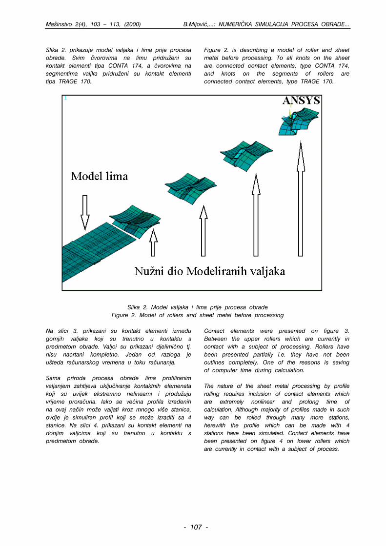
Mainstvo 2(4), 103 – 113, (2000) B.Mijovi,...: NUMERI^KA SIMULACIJA PROCESA OBRADE...
Slika 2. prikazuje model valjaka i lima prije procesa obrade. Svim ~vorovima na limu pridru`eni su kontakt elementi tipa CONTA 174, a ~vorovima na segmentima valjka pridru`eni su kontakt elementi tipa TRAGE 170.
Figure 2. is describing a model of roller and sheet metal before processing. To all knots on the sheet are connected contact elements, type CONTA 174, and knots on the segments of rollers are connected contact elements, type TRAGE 170.
Slika 2. Model valjaka i lima prije procesa obrade Figure 2. Model of rollers and sheet metal before processing
Na slici 3. prikazani su kontakt elementi izme|u gornjih valjaka koji su trenutno u kontaktu s predmetom obrade. Valjci su prikazani djelimi~no tj. nisu nacrtani kompletno. Jedan od razloga je uteda ra~unarskog vremena u toku ra~unanja. Sama priroda procesa obrade lima profiliranim valjanjem zahtijeva uklju~ivanje kontaktnih elemenata koji su uvijek ekstremno nelinearni i produ`uju vrijeme prora~una. Iako se veina profila izra|enih na ovaj na~in mo`e valjati kroz mnogo vie stanica, ovdje je simuliran profil koji se mo`e izraditi sa 4 stanice. Na slici 4. prikazani su kontakt elementi na donjim valjcima koji su trenutno u kontaktu s predmetom obrade.
Contact elements were presented on figure 3. Between the upper rollers which are currently in contact with a subject of processing. Rollers have been presented partially i.e. they have not been outlines completely. One of the reasons is saving of computer time during calculation. The nature of the sheet metal processing by profile rolling requires inclusion of contact elements which are extremely nonlinear and prolong time of calculation. Although majority of profiles made in such way can be rolled through many more stations, herewith the profile which can be made with 4 stations have been simulated. Contact elements have been presented on figure 4 on lower rollers which are currently in contact with a subject of process.
- 107 -
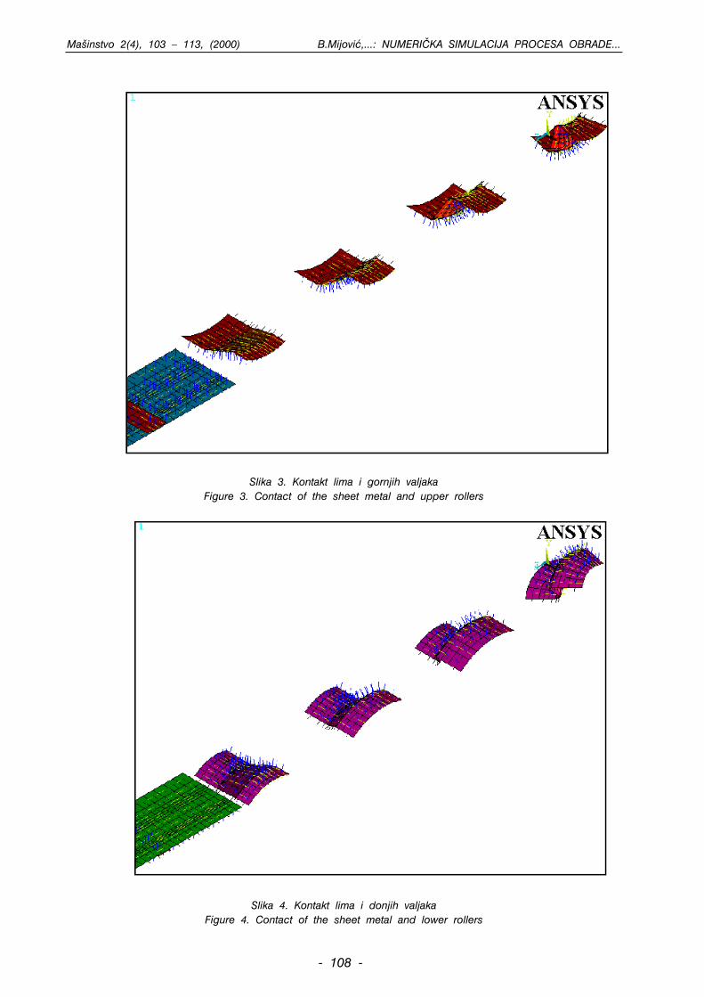
Mainstvo 2(4), 103 – 113, (2000) B.Mijovi,...: NUMERI^KA SIMULACIJA PROCESA OBRADE...
Slika 3. Kontakt lima i gornjih valjaka
Figure 3. Contact of the sheet metal and upper rollers
Slika 4. Kontakt lima i donjih valjaka
Figure 4. Contact of the sheet metal and lower rollers
- 108 -
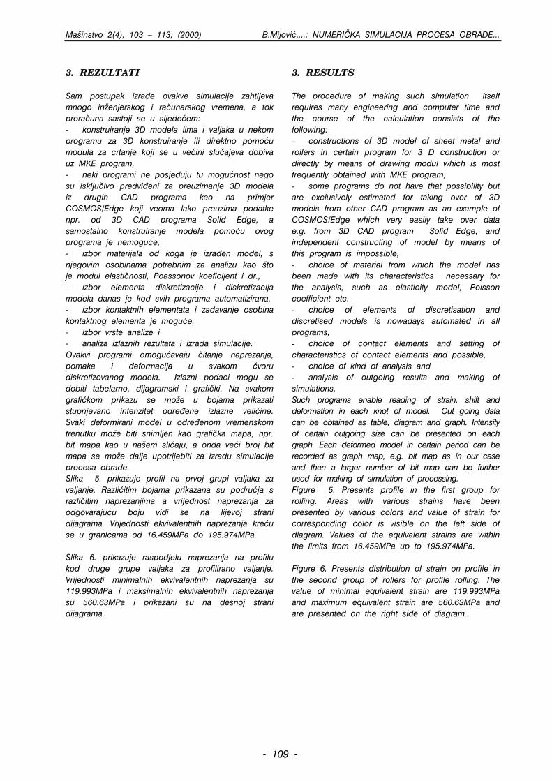
Mainstvo 2(4), 103 – 113, (2000) B.Mijovi,...: NUMERI^KA SIMULACIJA PROCESA OBRADE...
3. REZULTATI Sam postupak izrade ovakve simulacije zahtijeva mnogo in`enjerskog i ra~unarskog vremena, a tok prora~una sastoji se u sljedeem: - konstruiranje 3D modela lima i valjaka u nekom programu za 3D konstruiranje ili direktno pomou modula za crtanje koji se u veini slu~ajeva dobiva uz MKE program, - neki programi ne posjeduju tu mogunost nego su isklju~ivo predvi|eni za preuzimanje 3D modela iz drugih CAD programa kao na primjer COSMOS/Edge koji veoma lako preuzima podatke npr. od 3D CAD programa Solid Edge, a samostalno konstruiranje modela pomou ovog programa je nemogue, - izbor materijala od koga je izra|en model, s njegovim osobinama potrebnim za analizu kao to je modul elasti~nosti, Poassonov koeficijent i dr., - izbor elementa diskretizacije i diskretizacija modela danas je kod svih programa automatizirana, - izbor kontaktnih elementata i zadavanje osobina kontaktnog elementa je mogue, - izbor vrste analize i - analiza izlaznih rezultata i izrada simulacije. Ovakvi programi omoguavaju ~itanje naprezanja, pomaka i deformacija u svakom ~voru diskretizovanog modela. Izlazni podaci mogu se dobiti tabelarno, dijagramski i grafi~ki. Na svakom grafi~kom prikazu se mo`e u bojama prikazati stupnjevano intenzitet odre|ene izlazne veli~ine. Svaki deformirani model u odre|enom vremenskom trenutku mo`e biti snimljen kao grafi~ka mapa, npr. bit mapa kao u naem sli~aju, a onda vei broj bit mapa se mo`e dalje upotrijebiti za izradu simulacije procesa obrade. Slika 5. prikazuje profil na prvoj grupi valjaka za valjanje. Razli~itim bojama prikazana su podru~ja s razli~itim naprezanjima a vrijednost naprezanja za odgovarajuu boju vidi se na lijevoj strani dijagrama. Vrijednosti ekvivalentnih naprezanja kreu se u granicama od 16.459MPa do 195.974MPa. Slika 6. prikazuje raspodjelu naprezanja na profilu kod druge grupe valjaka za profilirano valjanje. Vrijednosti minimalnih ekvivalentnih naprezanja su 119.993MPa i maksimalnih ekvivalentnih naprezanja su 560.63MPa i prikazani su na desnoj strani dijagrama.
3. RESULTS The procedure of making such simulation itself requires many engineering and computer time and the course of the calculation consists of the following: - constructions of 3D model of sheet metal and rollers in certain program for 3 D construction or directly by means of drawing modul which is most frequently obtained with MKE program, - some programs do not have that possibility but are exclusively estimated for taking over of 3D models from other CAD program as an example of COSMOS/Edge which very easily take over data e.g. from 3D CAD program Solid Edge, and independent constructing of model by means of this program is impossible, - choice of material from which the model has been made with its characteristics necessary for the analysis, such as elasticity model, Poisson coefficient etc. - choice of elements of discretisation and discretised models is nowadays automated in all programs, - choice of contact elements and setting of characteristics of contact elements and possible, - choice of kind of analysis and - analysis of outgoing results and making of simulations. Such programs enable reading of strain, shift and deformation in each knot of model. Out going data can be obtained as table, diagram and graph. Intensity of certain outgoing size can be presented on each graph. Each deformed model in certain period can be recorded as graph map, e.g. bit map as in our case and then a larger number of bit map can be further used for making of simulation of processing. Figure 5. Presents profile in the first group for rolling. Areas with various strains have been presented by various colors and value of strain for corresponding color is visible on the left side of diagram. Values of the equivalent strains are within the limits from 16.459MPa up to 195.974MPa. Figure 6. Presents distribution of strain on profile in the second group of rollers for profile rolling. The value of minimal equivalent strain are 119.993MPa and maximum equivalent strain are 560.63MPa and are presented on the right side of diagram.
- 109 -
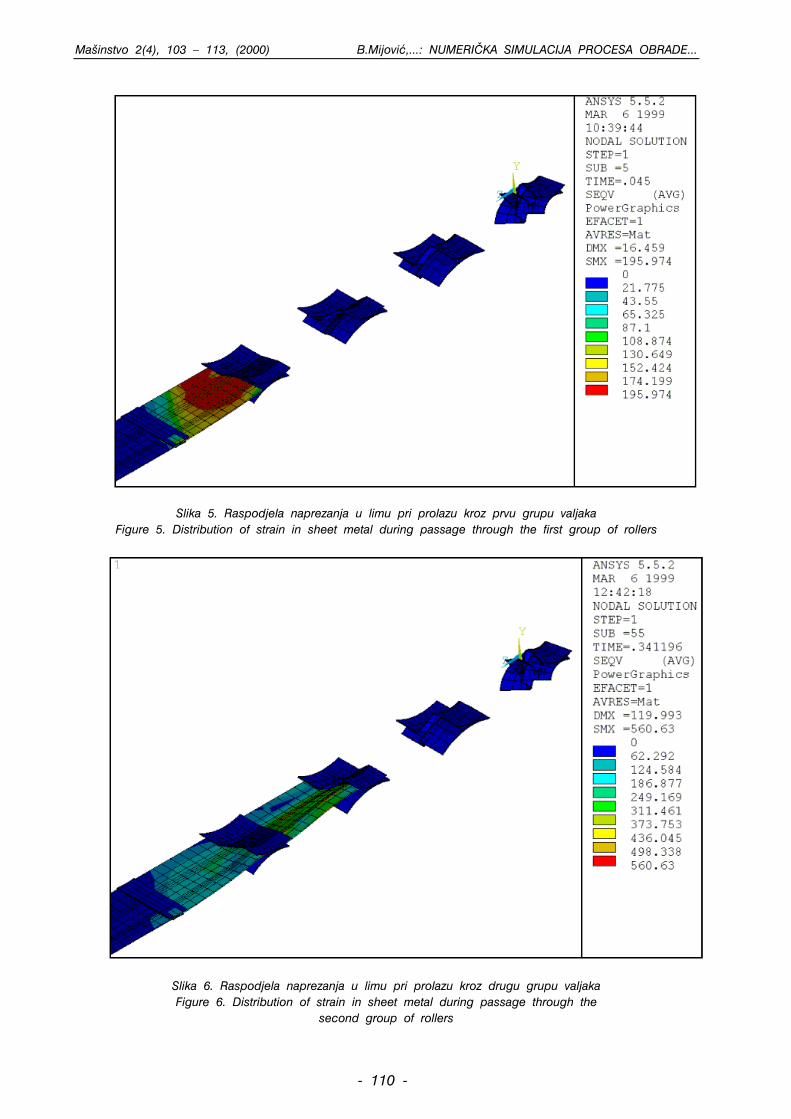
Mainstvo 2(4), 103 – 113, (2000) B.Mijovi,...: NUMERI^KA SIMULACIJA PROCESA OBRADE...
Slika 5. Raspodjela naprezanja u limu pri prolazu kroz prvu grupu valjaka
Figure 5. Distribution of strain in sheet metal during passage through the first group of rollers
Slika 6. Raspodjela naprezanja u limu pri prolazu kroz drugu grupu valjaka Figure 6. Distribution of strain in sheet metal during passage through the
second group of rollers
- 110 -
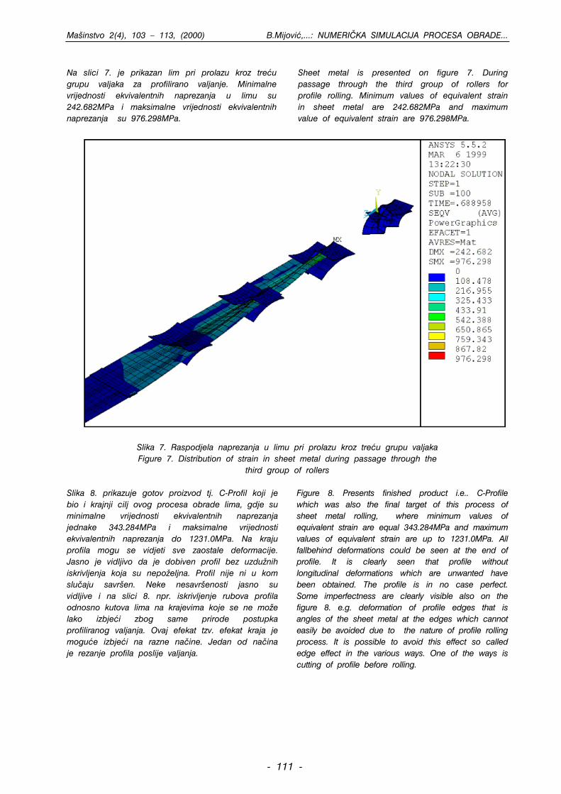
Mainstvo 2(4), 103 – 113, (2000) B.Mijovi,...: NUMERI^KA SIMULACIJA PROCESA OBRADE...
Na slici 7. je prikazan lim pri prolazu kroz treu grupu valjaka za profilirano valjanje. Minimalne vrijednosti ekvivalentnih naprezanja u limu su 242.682MPa i maksimalne vrijednosti ekvivalentnih naprezanja su 976.298MPa.
Sheet metal is presented on figure 7. During passage through the third group of rollers for profile rolling. Minimum values of equivalent strain in sheet metal are 242.682MPa and maximum value of equivalent strain are 976.298MPa.
Slika 7. Raspodjela naprezanja u limu pri prolazu kroz treu grupu valjaka Figure 7. Distribution of strain in sheet metal during passage through the
third group of rollers Slika 8. prikazuje gotov proizvod tj. C-Profil koji je bio i krajnji cilj ovog procesa obrade lima, gdje su minimalne vrijednosti ekvivalentnih naprezanja jednake 343.284MPa i maksimalne vrijednosti ekvivalentnih naprezanja do 1231.0MPa. Na kraju profila mogu se vidjeti sve zaostale deformacije. Jasno je vidljivo da je dobiven profil bez uzdu`nih iskrivljenja koja su nepo`eljna. Profil nije ni u kom slu~aju savren. Neke nesavrenosti jasno su vidljive i na slici 8. npr. iskrivljenje rubova profila odnosno kutova lima na krajevima koje se ne mo`e lako izbjei zbog same prirode postupka profiliranog valjanja. Ovaj efekat tzv. efekat kraja je mogue izbjei na razne na~ine. Jedan od na~ina je rezanje profila poslije valjanja.
Figure 8. Presents finished product i.e.. C-Profile which was also the final target of this process of sheet metal rolling, where minimum values of equivalent strain are equal 343.284MPa and maximum values of equivalent strain are up to 1231.0MPa. All fallbehind deformations could be seen at the end of profile. It is clearly seen that profile without longitudinal deformations which are unwanted have been obtained. The profile is in no case perfect. Some imperfectness are clearly visible also on the figure 8. e.g. deformation of profile edges that is angles of the sheet metal at the edges which cannot easily be avoided due to the nature of profile rolling process. It is possible to avoid this effect so called edge effect in the various ways. One of the ways is cutting of profile before rolling.
- 111 -
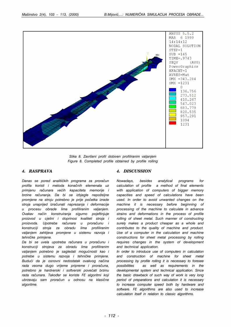
Mainstvo 2(4), 103 – 113, (2000) B.Mijovi,...: NUMERI^KA SIMULACIJA PROCESA OBRADE...
Slika 8. Zavreni profil dobiven profiliranim valjanjem Figure 8. Completed profile obtained by profile rolling
4. RASPRAVA Danas se pored analiti~kih programa za prora~un profila koristi i metoda kona~nih elemenata uz primjenu ra~unara veih kapaciteta memorije i brzine ra~unanja. Da bi se izbjegle nepo`eljne promjene na stroju potrebno je prije po~etka izrade stroja unaprijed izra~unati naprezanja i deformacije u procesu obrade lima profiliranim valjanjem. Ovakav na~in konstruiranja sigurno pojeftinjuje proizvod u cjelini i doprinosi kvaliteti stroja i proizvoda. Upotreba ra~unara u prora~unu i konstruciji stroja za obradu lima profiliranim valjanjem zahtijeva promjene u sistemu razvoja i tehni~ke primjene. Da bi se uvela upotreba ra~unara u prora~unu i konstruciji strojeva za obradu lima profiliranim valjanjem potrebno je sagledati mogunosti kao i potrebe u sistemu razvoja i tehni~ke primjene. Budui da je osnovni nedostatak ovakvog na~ina rada veoma dugo vrijeme pripreme i prora~una, potrebno je hardverski i softverski poveati brzinu rada ra~unara. Tako|er se koriste FE algoritmi koji ubrzavaju sam prora~un u odnosu na klasi~ne algoritme.
4. DISCUSSION Nowadays, besides analytical programs for calculation of profile a method of final elements with application of computers of bigger memory capacities and speed of calculations have been used. In order to avoid unwanted changes on the machine it is necessary before beginning of processing of the machine to calculate in advance strains and deformations in the process of profile rolling of sheet metal. Such manner of constructing surely makes a product cheaper as a whole and contributes to the quality of machine and product. Use of a computer in the calculation and machine constructions for sheet metal processing by rolling requires changes in the system of development and technical application. In order to introduce use of computers in calculation and construction of machine for sheet metal processing by profile rolling it is necessary to foresee possibilities as well as requirements in the developmental system and technical application. Since the basic drawback of such way of work is very long period of preparations and calculation it is necessary to increase computer speed both by hardware and software. FE algorithms are also used to increase calculation itself in relation to classic algorithms.
- 112 -
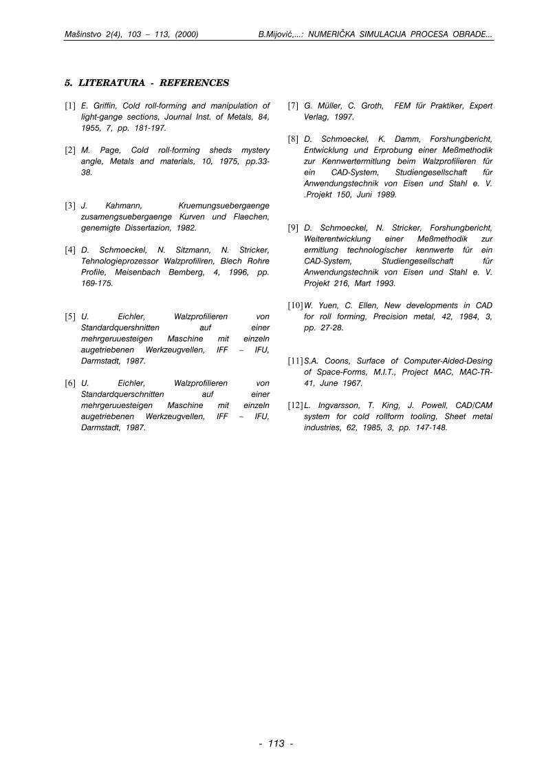
Mainstvo 2(4), 103 – 113, (2000) B.Mijovi,...: NUMERI^KA SIMULACIJA PROCESA OBRADE...
5. LITERATURA - REFERENCES [1] E. Griffin, Cold roll-forming and manipulation of
light-gange sections, Journal Inst. of Metals, 84, 1955, 7, pp. 181-197.
[2] M. Page, Cold roll-forming sheds mystery
angle, Metals and materials, 10, 1975, pp.33-38.
[3] J. Kahmann, Kruemungsuebergaenge
zusamengsuebergaenge Kurven und Flaechen, genemigte Dissertazion, 1982.
[4] D. Schmoeckel, N. Sitzmann, N. Stricker,
Tehnologieprozessor Walzprofiliren, Blech Rohre Profile, Meisenbach Bemberg, 4, 1996, pp. 169-175.
[5] U. Eichler, Walzprofilieren von
Standardquershnitten auf einer mehrgeruuesteigen Maschine mit einzeln augetriebenen Werkzeugvellen, IFF – IFU, Darmstadt, 1987.
[6] U. Eichler, Walzprofilieren von
Standardquerschnitten auf einer mehrgeruuesteigen Maschine mit einzeln augetriebenen Werkzeugvellen, IFF – IFU, Darmstadt, 1987.
[7] G. Müller, C. Groth, FEM für Praktiker, Expert
Verlag, 1997. [8] D. Schmoeckel, K. Damm, Forshungbericht,
Entwicklung und Erprobung einer Meßmethodik zur Kennwertermitlung beim Walzprofilieren für ein CAD-System, Studiengesellschaft für Anwendungstechnik von Eisen und Stahl e. V. .Projekt 150, Juni 1989.
[9] D. Schmoeckel, N. Stricker, Forshungbericht,
Weiterentwicklung einer Meßmethodik zur ermitlung technologischer kennwerte für ein CAD-System, Studiengesellschaft für Anwendungstechnik von Eisen und Stahl e. V. Projekt 216, Mart 1993.
[10] W. Yuen, C. Ellen, New developments in CAD
for roll forming, Precision metal, 42, 1984, 3, pp. 27-28.
[11] S.A. Coons, Surface of Computer-Aided-Desing
of Space-Forms, M.I.T., Project MAC, MAC-TR-41, June 1967.
[12] L. Ingvarsson, T. King, J. Powell, CAD/CAM
system for cold rollform tooling, Sheet metal industries, 62, 1985, 3, pp. 147-148.
- 113 -
Mainstvo 2(4), 115 - 123, (2000) A.Abazovi: IMPLEMENTACIJA STANDARDA ISO 9000...
- 111155 -
1. UVOD
Bosna i Hercegovina je Deklaracijom o usposta-
vljanju specijalnih veza sa Evropskom unijom
na~inila prvi korak u pribli`avanju ovoj integraciji.
Poto je ulazak u bilo koju regionalnu organizaci-
ju, pa i Evropsku uniju, uslovljen odre|enim za-
htjevima, Unija je u Bijeloj knjizi postavila uslove
koje zemlje kandidati trebaju ispuniti prije prijema.
IIMMPPLLEEMMEENNTTAACCIIJJAA SSTTAANNDDAARRDDAA IISSOO 99000000 UU NNEEKKIIMMPPRREEDDUUZZEE]]IIMMAA ZZEE - DDOO KKAANNTTOONNAA II UULLOOGGAA VVLLAADDEE
KKAANNTTOONNAA
Amir Abazovi, dipl. ma. in`, Ministarstvo industrije, energetike i rudarstvaZeni~ko-ddobojskog kantona, Kralja Tvrtka I 17, Zenica
REZIME
Aktualni trenutak u svijetu karakteriu procesi regionalizacije i globalizacije. Zemlje u tranziciji ula`uznatne napore u cilju implementacije postavljenih kriterija sadr`anih u Bijeloj knjizi Evropske unije. Utim nastojanjima zna~ajnu ulogu ima PHARE program i njegovi podprogrami. Za stvaranje kompatibil-nih sistema u oblasti standardizacije koristi se PHARE-PRAQ III program. U cilju obezbje|enja pristu-pa evropskom i svjetskom tr`itu, te podsticanju podizanja konkurentske sposobnosti preduzea, VladaZeni~ko-dobojskog kantona i Ministarstvo industrije, energetike i rudarstva su poduzeli niz aktivnosti zaimplementaciju standarda ISO 9000.
Klju~ne rije~i: implementacija, standardi ISO 9000, firme ZE-DO kantona, uloga Vlade kantona
TTHHEE IIMMPPLLEEMMEENNTTAATTIIOONN OOFF TTHHEE IISSOO 99000000 SSTTAANNDDAARRDDIINN AANNYY FFIIRRMMSS IINN ZZEE-DDOO CCAANNTTOONN AANNDD TTHHEE RROOLLEE OOFF
TTHHEE CCAANNTTOONNAALL GGOOVVEERRNNMMEENNTT
Amir Abazovi, B.Sc. Mechanical Engineer, Ministry of Industry, Energetics andMining for the Zenica-DDoboj Canton, Kralja Tvrtka I 17, Zenica
SUMMARY
The current situation in the world is characterised by the processes of regionalization and globaliza-tion. The countries in transition put great effort in implementation of the criteria laid down in theEuropean Union White Paper. The PHARE programme and its subprogrammes play an important rolein those efforts. The PHARE-PRAQ III programme is used in crating the compatible systems in thefield of standardization. In order to provide access to the European and the world market, as wallas in order to support the firm competitiveness to raise, the Government of the ZE-DO canton andthe Ministry of Industry, Energetics and Mining have taken steps to implement the ISO 9000 stan-dard.
Key words: implementation, ISO 9000 standards, firms in ZE-DO canton, the role of the cantonalgovernment
1. INTRODUCTION
With the Declaration of establishing special relation-ship with the European Union, Bosnia andHerzegovina made the first step in getting closer tothis integration. Since the admission to any regionalorganization, the European Union as well, is condi-tioned by certain demands, the Union has laid downthese demands in the white Paper, which the coun-
SSTTRRUU^NNII RRAADD
PPRROOFFEESSSSIIOONNAALL PPAAPPEERR
Za punopravno ~lanstvo u Evropskoj uniji neopho-
dno je usvojiti kompletno naslije|e u oblasti le-
gislative, standardizacije i prakse u 23 razli~ita se-
ktora. Za takve poslove mnoge zemlje, a posebno
one u tranziciji anga`ovale su hiljade stru~njaka.
Pored toga, istim uslovima je odre|en pristup
mnogim drugim tr`itima razvijenih zemalja i zema-
lja u razvoju, za ~lanstvo u svjetskoj trgovinskoj
organizaciji (WTO) i za potpisivanje mnogih spo-
razuma i ugovora kojima se onemoguavaju bari-
jere kretanja roba i usluga. S obzirom na obim i
specifi~nu te`inu implementacije zahtjeva iz Bijele
knjige, Evropska unija je organizirala poseban pro-
gram. To je PHARE PROGRAM. Ova inicijativa
Evropske unije omoguuje obezbje|enje nepovrat-
nih sredstava i drugih pogodnosti "partnerskim
zemljama", kao pomo u procesu tranzicije i
ekonomski i politi~ki centralizovanog sistema ka
decentralizovanoj tr`inoj ekonomiji i demokratskom
drutvu do stepena prihvatanja obaveza koje nosi
~lanstvo u Evropskoj uniji. Iz fonda PHARE PRO-
GRAMA podr`ava se 40 "Multi - country" i
"Horizontal" programa u zemljama tranzicije. Bosni
i Hercegovini su podneseni dokumenti za 32 pro-
grama, a aktivno u~ee je uzeto u njih 14. Za
oblast kojom se bavimo, posebno zna~ajan je pro-
gram PRAQ III koji podr`ava oblast standardizaci-
je i kvaliteta. S obzirom na kona~ne ciljeve i
zna~aj poduzimanja konkretnih aktivnosti na imple-
mentaciji zahtjeva Bijele knjige, Vlada i Ministarstvo
za industriju Zeni~ko - dobojskog kantona opre-
dijelila se za pru`anje finansijske pomoi pre-
duzeima koja su ula ili namjeravaju ui u pro-
ces uvo|enja standarda ISO 9000. Radi zna~aja
svih prethodno navedenih pojmova i `elja da se i
drugi faktori u naem ambijentu anga`iraju na ovim
pitanjima, u nastavku teksta bit e izneene najbit-
nije ~injenice o svakom pojedina~no.
2. BIJELA KNJIGA (WHITE PAPER)
Ovo je osnovni dokument Evropske unije, sa~injenna 438 stranica teksta A4 formata, gdje su navedenisvi uslovi koje zemlje u tranziciji moraju obezbijedi-ti kako bi im se omoguilo punopravno ~lanstvo uovoj presti`noj organizaciji. Dakle, zemlje centralne iisto~ne Evrope trebaju implementirati elementeunutarnje organizacije prema modelu Evropske unije.Takav model podrazumijeva sistem parlamentarnedemokracije sa institucijama koje tite pravagra|anina i ure|eno tr`ite koje obezbje|uje
Mainstvo 2(4), 115 - 123, (2000) A.Abazovi: IMPLEMENTACIJA STANDARA ISO 9000...
- 111166 -
tries candidates need to fulfill before being admittedinto the Union. In order to become a full member ofthe European Union, it is necessary to adapt its her-itage in the field of legislature, standardization andpractice in 23 different sectors. Many countries, espe-cially those in transition, have engaged thousands ofexperts to do that work. Apart from that, the accessto many other markets of the developed as well asdeveloping countries, the membership in the WorldTrade Organization (WTO) and the signing of manyagreements and contracts which would remove bar-riers in the flow of goods and services are condi-tioned by the same demands. Considering the scaleand the importance of the implementation of thedemands from the White Book, the European Unionhas organized a special programme. It is called thePHARE programme. This initiative taken by theEuropean Union enables the "countries in partnership"to get irretrievable funds as well as other conve-niences as aid in the transition of an economicallyand politically centralised system towards a decen-tralised market economy and democratic society to adegree of being able to accept the commitments ofthe European Union membership. Forty "Multi-country"and "Horizontal" programmes in the countries in tran-sition are supported from the PHARE PROGRAMMEfunds. The documents for 32 programmes were pre-sented to Bosnia and Herzegovina, and the countrybecame actively involved in 14 of them. For the fieldin which we work, especially important is the PRAQIII, which supports the area of standardization andquality. Considering the ultimate goals and the rele-vance of taking concrete steps in the implementationof the white Paper demands, the Government andthe Ministry of Industry for the Zenica-Doboj Cantonhave decided to give a financial support to the firmswhich started or intend to start with introducing theISO 9000 standard. Because of the relevance of allthe above mentioned terms and the wishes for allother factors in our society to engage in theseissues, the most important facts about each item willa delivered in text that follows.
2. THE WHITE PAPER
That is the basic document of the European Union,made on 438 pages of text, in the A4 format, whereall the demands for the countries in transition to ful-fill in order to become full members in this presti-gious organization are stated. Therefore, the coun-tries of Central and East Europe need to implementthe elements of their internal organization accordingto the European Union model. This model includesa system of parliamentary democracy with institu-tions protecting the rights of citizens and an estab-
lished market which provides competitiveness with-out monopoly, which protect health and lives of cit-izens and their environment, which protect the con-sumers' interests, enables the frow of people andcapital and tabes corrective actions against thosewho destroy such model. For the implementation ofthis model, the European Union provides concreteaid. According to the White Paper demands, the"countries in Partnership" are obliged to coordinatetheir legislation, their standards and their practice in23 sectors, which are:1. Free flow of capital,2. Free flow and safety of industrial products,3. Free competition and apposition to monopoly,4. Social politics and action,5. Agriculture,6. Transport,7. Audio-visual services,8. Environment,9. Telecommunication,10. Direct taxation,11. Free flow of goods in nonharmonized or partlyharmonized sectors,12. Public supply,13. Financial services,14. Protection of personal information,15. The laws of firms,16. Accountancy,17. Civil engineering laws,18. Mutual verification of professional qualifications,19. Intellectual, industrial and commercial property,20. Energy,21. Customs Union,22. Indirect taxation,23. Consumer protection policy.
The demands in all the above sectors are based
on the Directives, i.e. the norms of the European
Union. In order to efficiently coordinate the White
Paper demands, the general national programmes
can be made. It is obvious that the factors of time
and people are the basic resources which need to
be provided for the efficient implementation. Some
countries have engaged thousands of experts to
work on the implementation process.
3. THE PHARE PROGRAMME
The PHARE PROGRAMME is the initiative of theEuropean Union, which provides grants (irretrievableones) to the "countries in partnership" (the countriesof Central and fast Europe - countries in transition)as an aid for the creating of models which are com-patible to the European Union model. The programme
konkurenciju bez monopola, tite zdravlje i `ivotgra|ana, titi okolinu, tite interes potroa~a,omoguavaju slobodan protok ljudi i kapitala, teobezbje|uju vo|enje korektivnih mjera prema onimakoji taj model naruavaju. Za implementaciju ovogmodela Evropska unija obezbje|uje konkretnupomo za njegovu primjenu u praksi. Prema zahtje-vima Bijele knige "zemlje partneri" su obavezni uskla-diti svoju legislativu, standarde i praksu u 23 sek-tora, a to su:1. slobodan protok kapitala,2. slobodan protok i sigurnost industrijskih proizvoda, 3. slobodna konkurencija i suprotstavljanje monopola,4. socijalna politika i akcija,5. poljoprivreda,6. transport,7. audio vizuelne usluge,8. okolina,9. telekomunikacija,10. direktno oporezivanje,11. slobodno kretanje roba u neharmoniziranim ilidjelimi~no harmoniziranim sektorima, 12. javno snabdjevanje,13. finansijske usluge,14. zatita li~nih podataka,15. zakon o kompanijama,16. ra~unovodstvo,17. gra|evinsko pravo,18. uzajamno priznavanje profesionalnih kvalifikacija,19. intelektualna, industrijska i komercijalna svojina,20. energija,21. carinska unija,22. indirektno oporezivanje,23. politika zatite potroa~a.
Uslovi u svim navedenim sektorima zasnovani su na
donesenim Direktivama, odnosno normama
Evropske unije. U cilju efikasnog usaglaavanja
zahtjeva iz Bijele knjige, omogueno je da se
sa~ine nacionalni okvirni programi. O~igledno su
faktori vrijeme i ~ovjek osnovni resursi koje treba
obezbijediti za efikasnu implementaciju. Neke ze-
mlje su anga`irale na hiljade stru~njaka koji rade
na ovim poslovima.
3. PHARE PROGRAM
PHARE PROGRAM je inicijativa Evropske unije koja
pru`a grant (nepovratna) sredstva "partnerskim ze-
mljama" (zemljama centralne i isto~ne Evrope - ze-
mljama u tranziciji) kao pomo u stvaranju kompa-
tibilnih modela modelu Evropske unije. Program je
Mainstvo 2(4), 115 - 123, (2000) A.Abazovi: IMPLEMENTACIJA STANDARDA ISO 9000...
- 111177 -
kreiran 1989. godine sa ciljem podrke reformama
u Poljskoj i Ma|arskoj. Trenutno je glavni finansijski
instrument Evropske unije za saradnju sa 13 "part-
nerskih zemalja" (Albanija, BiH, Bugarska, ^eka
Republika, Estonija, Makedonija, Ma|arska, Latvija,
Litvanija, Poljska, Rumunija, Slova~ka Republika i
Slovenija). Program je obezbijedio znatna finansijska
sredstva. Za 40 multi - country PHARE PROGRAMA
i po jedan nacionalni PHARE PROGRAM za svaku
zemlju korisnicu do sada je utroeno vie od 8 mi-
lijardi DEM. PHARE PROGRAM obezbje|uje veliki
broj instrumenata za podrku procesa reformi, a prije
svega:
1. know - how (pru`anje savjeta, konsultacije, obuka,
razvoj legislative i regulative i pokretanje okvirnih
programa i pilot projekata),
2. podrka investiranju (studije, grantovi, garancije i
kreditne linije),
3. investiranje u infrastrukturu (sufinansiranje, razvoj
transevropskih mre`a i kvalitetne linije).
Program se u "zemljama partnerima" realizuje
kroz nacionalne programe, koje koriste PHARE
zemlje samostalno, kao i programe koje zajed-
ni~ki koristi vie zemalja ("Multi - country" i
"Horizontal" programi, koji su 1998. godine pre-
rasli u "Multi - beneficiary" programe). Bosna i
Hercegovina je uklju~ena u obje vrste programa.
Od ukupno 40 programa Bosni i Hercegovini su
podneseni dokumenti za 32 programa, a aktivno
je uzeto u~ee u njih 14. To su slijedei pro-
grami:
1. ACE - Action for Cooperation in the Field of
Economics
2. CREDO - East - East Cross - Border Cooperation
3. CUSTOMS
4. DISTANCE LEARNING
5. ENERGY
6. ENVIRONMENT
7. FIGHT AGAINST DRUGS
8. HIGHER EDUCATION (u BiH pokriva aktivnost na
TEMPUS programu)
9. PRAQ III - Quality Assurance/ Standards
10. RIPP - Industrial Property
11. STATISTICS
12. TELEKOMUNICATIONS
13. TRADE
14. TRANSPORT
Koordinacija PHARE PROGRAMA za BiH se vri
putem Ureda nacionalnog PHARE koordinatora koji
djeluje pri Ministarstvu vanjskih poslova BiH.
Mainstvo 2(4), 115 - 123, (2000) A.Abazovi: IMPLEMENTACIJA STANDARA ISO 9000...
- 111188 -
was created in 1989 in order to support the reformsin Poland and Hungary. It is, currently, the main finan-cial instrument of the European Union for coopera-tion with 13 "Countries in partnership" (Albania, B&H,Bulgaria, Czech Republic, Estonia, Macedonia,Hungary, Latvia, Lithuania, Poland, Romania, Slovakiaand Slovenia). The programme has provided consid-erable financial resources. Up to now, for the 4omulti-country PHARE PROGRAMMES and one nation-al PHARE PROGRAMME for each recipient country,more than 8 billion DM has been sport. The PHAREPROGRAMME provides a great number of instrumentsfor the support of the reform process, before all:1. know-how (offering advice, consultations, training,development of legislation and regulation and stat-ing the general programmes and pilot projects),2. investment support (studies, grants, vouchers andcredit lines),3. investment in infrastructure (co-financing, devel-opment of trans-European networks and qualitylines).
In the "countries in partnership", the programme isrealized through the national programmes witch thePHARE countries use independently, as well asthrough programmes which are pointy used by sev-eral countries the "Multi-country" and "Horizontal"programmes, which, in 1998, grew info the "Multi-beneficiary programmes). Bosnia and Herzegovina isengaged info bath those types of programmes. Outof 40 programmes, the documents of 32 of themwere presented to Bosnia and Herzegovina, and thecountry is actively involved info 14 programmes.These are:1. ACE - Action for Cooperation in the FIeld ofEconomics2. CREDO - East _ East Cross - Border Cooperation3. CUSTOMS4. DISTANCE LEARNING5. ENERGY6. ENVIRONMENT7. FIGHT AGAINST DRUGS8. HIGHER EDUCATION (This activity in B&H is con-ducted through the TEMPUS programme)9. PRAQ III - Quality Assurance/Standards10. RIPP - Industrial Property11. STATISTICS12. TELECOMMUNICATIONS13. TRADE14. TRANSPORT
The PHARE PROGRAMME for B&H is coordinatedby the National PHARE Coordinator Office, whichoperates from the Ministry of Foreign Affairs forB&H.
4. PHARE - PRAQ III PROGRAM
Program PRAQ III je klju~ni element strategijezemalja isto~ne i srednje Evrope i Evropske unijeza uspostavljanje me|usobnog povjerenja. Onodra`ava stavove Evropske komisije iznesenih uBijeloj knjizi za integraciju u tr`ite Evropske unije.Ovaj program obezbje|uje implementaciju legisla-tive tr`ita, standardizacije, ocjenjivanjausaglaenosti, te zakonskog i industrijskogmjeriteljstva. Sredstva namijenjena za finansiranjeprograma PHARE PRAQ III Evropska komisija usm-jerava za provo|enje direktiva novog pristupa i se-ktorskih direktiva, prevo|enje harmoniziranih evro-pskih standarda, akcije na podizanju svijesti ozna~aju ovih aktivnosti kod svih ljudi koji u~estvu-ju u donoenju odluka, te mnoge druge zna~ajneaktivnosti. Poseban zna~aj se posveuje pomoiuvo|enja sistema ISO 9000 pri izgradnjinacionalnog sistema za standardizaciju, akreditacijui mjeriteljstvo. Ciljevi ovog projekta su:- pomo u uspostavi odgovarajuih uslova za pri-hvatanje zajedni~kih principa usaglaenosti sa sta-ndardima, propisima i harmonizaciji standarda,mjeriteljstva i prakse upravljanja kvalitetom sa si-stemima koji se koriste u Evropskoj uniji,- pomo zemljama potpisnicama ugovora uunapre|enju upravljanja kvalitetom da bi one moglesnabdijevati svoje tr`ite proizvodima boljeg kvalitetai da bi postigle vii nivo konkurentnosti na me|una-rodnom tr`itu,- promoviranje generalnog usvajanja principaEvropske unije u sektorima industrije i trgovine, topodrazumijeva ne samo modernu legislativu i insta-lacione strukture, ve i nove pristupe i praksu unutarinstitucija koje donose javne propise kao i u priva-tnom sektoru,- olakavanje, u skladu sa Bijelom knjigom, promo-cija trgovine sa Evropskom unijom stvaranjempovoljnih uslova za me|unarodno priznavanje testo-va usaglaenosti proizvoda sa uspostavljenim indu-strijskim standardima, to prakti~no zna~i me|uso-bno priznavanje certifikata, znakova usaglaenosti iizvjetaja o ispitivanju.O~igledno zna~aj programa PRAQ III namee potre-bu anga`mana svih relevantnih faktora na imple-mentaciji njegovih elemenata. To je bio razlog daMinistarstvo za industriju, energetiku i rudarstvoZeni~ko - dobojskog kantona neposredno po svomformiranju 1996. godine poduzme odre|ene aktivno-sti na pribli`avanju njegovog zna~aja privrednim su-bjektima. U sklopu ovih aktivnosti poseban zna~aj jeposveen uvo|enju standarda iz porodice ISO 9000u preduzeima sa podru~ja Zeni~ko - dobojskogkantona.
Mainstvo 2(4), 115 - 123, (2000) A.Abazovi: IMPLEMENTACIJA STANDARDA ISO 9000...
- 111199 -
4. PHARE - PRAQ III PROGRAMME
The PRAQ III Programme is the bay element of thestrategy of Western and Central European countriesas well as of the European Union for establishingthe integration info the market of the EuropeanUnion, the attitudes which of the market legislation,the standardization, the evaluation of the coordina-tion as well as law and industrial standards. TheEuropean Commission has directed the resourcesfor the financing of the PHARE-PRAQ III Programmeinfo the implementation of the hew programmedirectives as well as the sector directives, theimplementation of the harmonized European stan-dards, the activity on the raising public awarenessof the importance of this issue and many otherimportant activities. Special emphasis is placed onsupporting the implementation of the ISO 9000 sys-tem in establishing the national standardization,accreditation and evaluation systems. The objectivesof this projects are as follows:- support in establishing adequate conditions foraccepting common principles in coordination of stan-dards and regulations ar well as in the harmoniza-tion of standards, evaluations and practice in quali-ty management systems used in the European Union,
- support to the countries - partners in agreement
in improving their quality management in order to
supply their markets with the products of higher
quality and in order to achieve a greater level of
competitiveness on the international market,
- promoting the general adoption of the European
Union principles in the industry and trade sectors,
which implies not only modern legislation and instal-
lation structures, bat new approaches and practice
within the institutions which pass public regulations
and within the private sector as well,- facilitating, according to the white Paper, the promo-tion of trade with the European Union by creating favor-able conditions for the international verification of thecoordination test for products with established industrialstandards, which practically means mutual verification ofcertificates, coordination and research reports.Obviously, the importance of the PRAQ IIIProgramme stresses the need for the engagementof all the relevant factors in the implementation ofits elements. This was the reason for the Ministryof Industry, Energetics and Mining for the Zenica-Doboj Canton to, immediately after its establishingin 1996, take certain steps in bringing the relevanceof the programme closer to the business structures.one of these activities, on which great emphasiswas placed, is introducing of the ISO 9000 standardinfo the firms from the area of the Zenica-DobojCanton.
5. THE IMPLEMENTATION OF THE ISO9000 STANDARD IN SOME FIRMS INTHE ZE-DDO CANTON AND THE ROLEOF THE CANTONAL GOVERNMENT
The need for an organized approach to the
process of introducing the ISO standard info the
firms was repeatedly stressed during many meet-
ings with the bussinesmen from the ZE-Do
Canton. In mid 1997, there was a presentation of
the PRAQ III Programme, the ISO 9000 standard
and the ways of their implementation, held in
front of approximately 100 managers from the area
of the ZE-DO Canton. All the activities were
according to a plan, with the main objective to
renew the production and raise the competitive-
ness of firms. The economy of the ZE-DO Canton
suffered great damage during the war. Many
important production capacities were destroyed.
Many business relationships with partners from
B&H and abroad were cut off. During the war and
immediately before the war there was a significant
technological falling behind in relation to the sur-
roundings. In the years immediately after the war,
the firms tries to re-establish the pre-war rela-
tionships with their business partners. But there
were numerous signs of changes in the interna-
tional market, so that the processes of renewal
went pretty slowly. One of the most important ele-
ments in business, which has grown in impor-
tance in Europe and the world during the last fif-
teen years (especially during the war in B&H) is
the quality system defined by the ISO 9000 stan-
dards. The "Zenica" Steelworks, "Pobjeda", "Unico-
filter" and "Enker" Teanj were among the first to
receive the certificates by the ISO 9000 standard.
This was possible because there firms had devel-
oped quality systems even before the war, and
because they had been present at the interna-
tional market, where these standards were
required. Apart from the above reasons for intro-
ducing the ISO Standard, the firms in the renew-
al process also had in mind very important effects
they were able to achieve during the implemen-
tation itself, as well as after receiving the certifi-
cate. These can be, in short, specified as:- the ability of increasing profitability,- the motivation of the employees in increased forseveral reasons (the staff is not burdened with cor-recting mistakes in demands to meet the deadlines,and is not targeted by unsatisfied consumers; theprocedures are defined; independent auditor and
5. IMPLEMENTACIJA STANDARDAISO 9000 U NEKIM PREDUZE]IMAZE - DO KANTONA I ULOGA VLADEKANTONA
U vie navrata, na raznim susretima sa privred-
nicima sa podru~ja Zeni~ko - dobojskog kantona
isticana je potreba organizovanog ulaska u proces
uvo|enja ISO standarda u preduzea. Sredinom
1997. godine izvrena je sveukupna prezentacija
programa PRAQ III, standarda ISO 9000 i
mogunosti njihove implementacije pred oko 100
direktora preduzea sa podru~ja Zeni~ko - dobo-
jskog kantona. Sve aktivnosti su vo|ene planski,
sa ciljem obnove proizvodnje i podizanja
konkurentne sposobnosti preduzea. Privreda na
podru~ju Kantona tokom rata pretrpjela je znatne
tete. Uniteni su zna~ajni proizvodni kapaciteti.
Prekinute su poslovne veze sa mnogim partnerima
kako u BiH tako i u ino-stranstvu. Tokom ratnih
godina, a i neposredno prije rata dolo je do
vidnog tehnolokog zaostajanja u odnosu na ire
okru`enje. Tokom prvih poratnih godina preduzea
su pokuavala uspostaviti predratne odnose sa
poslovnim partnerima. Me|utim, mnogi pokazatelji
su ukazivali da je na me|unarodnom tr`itu dolo
do znatnih promjena, tako da su procesi obnove
ili dosta sporo. Jedan od posebno zna~ajnih ele-
menata poslovanja, koji je u posljednjih petnaest
godina (posebno u toku ratnog perioda u BiH),
dobio na zna~aju u Evropi i svijetu, jeste sistem
kvaliteta definiran po standardima ISO 9000.
Spoznaja neophodnosti stvaranja kompatibilnih si-
stema kvaliteta sa partnerima iz ireg okru`enja,
utjecala je da su neka preduzea vrlo brzo ula
u proces uvo|enja ISO standarda. Tako su
@eljezara "Zenica", "Pobjeda", "Unico - filter", i
"Enker" Teanj me|u prvima obezbijedili certifikate
po ISO 9000. Ovo je bilo mogue iz razloga to
su ova preduzea i prije rata posjedovala
izgra|ene sisteme kvaliteta, te zbog toga to su u
veoj mjeri bila prisutna na ino - tr`itu gdje su
se pomenuti standardi tra`ili. Pored navedenih
razloga za uvo|enje ISO standarda, preduzea su
u procesu obnove imala na umu i vrlo zna~ajne
efekte koje je bilo mogue postii u toku uvo|enja
i po dobivanju certifikata. Oni se mogu u
najkraem specificirati kao:- mogunost poveanja rentabilnosti,
- motivisanost zaposlenih se poveava iz vie razlo-
ga (osoblje nije optereeno ispravljanjem greaka u
zahtjevima da se pridr`ava rokova, te nije na meti
nezadovoljnih kupaca; definiraju se procedure; neza-
Mainstvo 2(4), 115 - 123, (2000) A.Abazovi: IMPLEMENTACIJA STANDARA ISO 9000...
- 112200 -
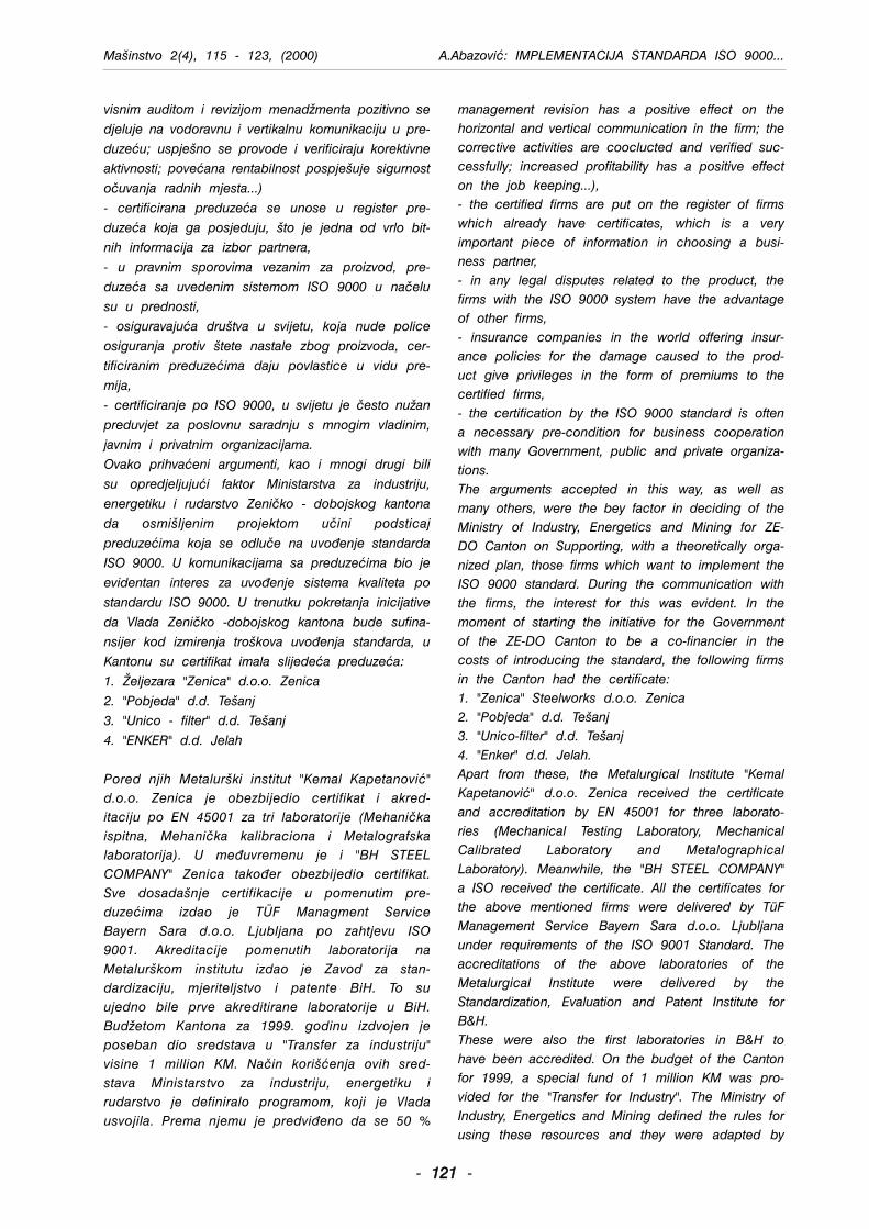
visnim auditom i revizijom menad`menta pozitivno se
djeluje na vodoravnu i vertikalnu komunikaciju u pre-
duzeu; uspjeno se provode i verificiraju korektivne
aktivnosti; poveana rentabilnost pospjeuje sigurnost
o~uvanja radnih mjesta...)
- certificirana preduzea se unose u register pre-
duzea koja ga posjeduju, to je jedna od vrlo bit-
nih informacija za izbor partnera,
- u pravnim sporovima vezanim za proizvod, pre-
duzea sa uvedenim sistemom ISO 9000 u na~elu
su u prednosti,
- osiguravajua drutva u svijetu, koja nude police
osiguranja protiv tete nastale zbog proizvoda, cer-
tificiranim preduzeima daju povlastice u vidu pre-
mija,
- certificiranje po ISO 9000, u svijetu je ~esto nu`an
preduvjet za poslovnu saradnju s mnogim vladinim,
javnim i privatnim organizacijama.
Ovako prihvaeni argumenti, kao i mnogi drugi bili
su opredjeljujui faktor Ministarstva za industriju,
energetiku i rudarstvo Zeni~ko - dobojskog kantona
da osmiljenim projektom u~ini podsticaj
preduzeima koja se odlu~e na uvo|enje standarda
ISO 9000. U komunikacijama sa preduzeima bio je
evidentan interes za uvo|enje sistema kvaliteta po
standardu ISO 9000. U trenutku pokretanja inicijative
da Vlada Zeni~ko -dobojskog kantona bude sufina-
nsijer kod izmirenja trokova uvo|enja standarda, u
Kantonu su certifikat imala slijedea preduzea:
1. @eljezara "Zenica" d.o.o. Zenica
2. "Pobjeda" d.d. Teanj
3. "Unico - filter" d.d. Teanj
4. "ENKER" d.d. Jelah
Pored njih Metalurki institut "Kemal Kapetanovi"d.o.o. Zenica je obezbijedio certifikat i akred-itaciju po EN 45001 za tri laboratorije (Mehani~kaispitna, Mehani~ka kalibraciona i Metalografskalaboratorija). U me|uvremenu je i "BH STEELCOMPANY" Zenica tako|er obezbijedio certifikat.Sve dosadanje certifikacije u pomenutim pre-duzeima izdao je TÜF Managment ServiceBayern Sara d.o.o. Ljubljana po zahtjevu ISO9001. Akreditacije pomenutih laboratorija naMetalurkom institutu izdao je Zavod za stan-dardizaciju, mjeriteljstvo i patente BiH. To suujedno bile prve akreditirane laboratorije u BiH.Bud`etom Kantona za 1999. godinu izdvojen jeposeban dio sredstava u "Transfer za industriju"visine 1 million KM. Na~in korienja ovih sred-stava Ministarstvo za industriju, energetiku irudarstvo je definiralo programom, koji je Vladausvojila. Prema njemu je predvi|eno da se 50 %
Mainstvo 2(4), 115 - 123, (2000) A.Abazovi: IMPLEMENTACIJA STANDARDA ISO 9000...
- 112211 -
management revision has a positive effect on thehorizontal and vertical communication in the firm; thecorrective activities are cooclucted and verified suc-cessfully; increased profitability has a positive effecton the job keeping...),- the certified firms are put on the register of firmswhich already have certificates, which is a veryimportant piece of information in choosing a busi-ness partner,- in any legal disputes related to the product, thefirms with the ISO 9000 system have the advantageof other firms,- insurance companies in the world offering insur-ance policies for the damage caused to the prod-uct give privileges in the form of premiums to thecertified firms,- the certification by the ISO 9000 standard is oftena necessary pre-condition for business cooperationwith many Government, public and private organiza-tions.The arguments accepted in this way, as well asmany others, were the bey factor in deciding of theMinistry of Industry, Energetics and Mining for ZE-DO Canton on Supporting, with a theoretically orga-nized plan, those firms which want to implement theISO 9000 standard. During the communication withthe firms, the interest for this was evident. In themoment of starting the initiative for the Governmentof the ZE-DO Canton to be a co-financier in thecosts of introducing the standard, the following firmsin the Canton had the certificate:1. "Zenica" Steelworks d.o.o. Zenica2. "Pobjeda" d.d. Teanj3. "Unico-filter" d.d. Teanj4. "Enker" d.d. Jelah.Apart from these, the Metalurgical Institute "KemalKapetanovi" d.o.o. Zenica received the certificateand accreditation by EN 45001 for three laborato-ries (Mechanical Testing Laboratory, MechanicalCalibrated Laboratory and MetalographicalLaboratory). Meanwhile, the "BH STEEL COMPANY"a ISO received the certificate. All the certificates forthe above mentioned firms were delivered by TüFManagement Service Bayern Sara d.o.o. Ljubljanaunder requirements of the ISO 9001 Standard. Theaccreditations of the above laboratories of theMetalurgical Institute were delivered by theStandardization, Evaluation and Patent Institute forB&H.These were also the first laboratories in B&H tohave been accredited. On the budget of the Cantonfor 1999, a special fund of 1 million KM was pro-vided for the "Transfer for Industry". The Ministry ofIndustry, Energetics and Mining defined the rules forusing these resources and they were adapted by
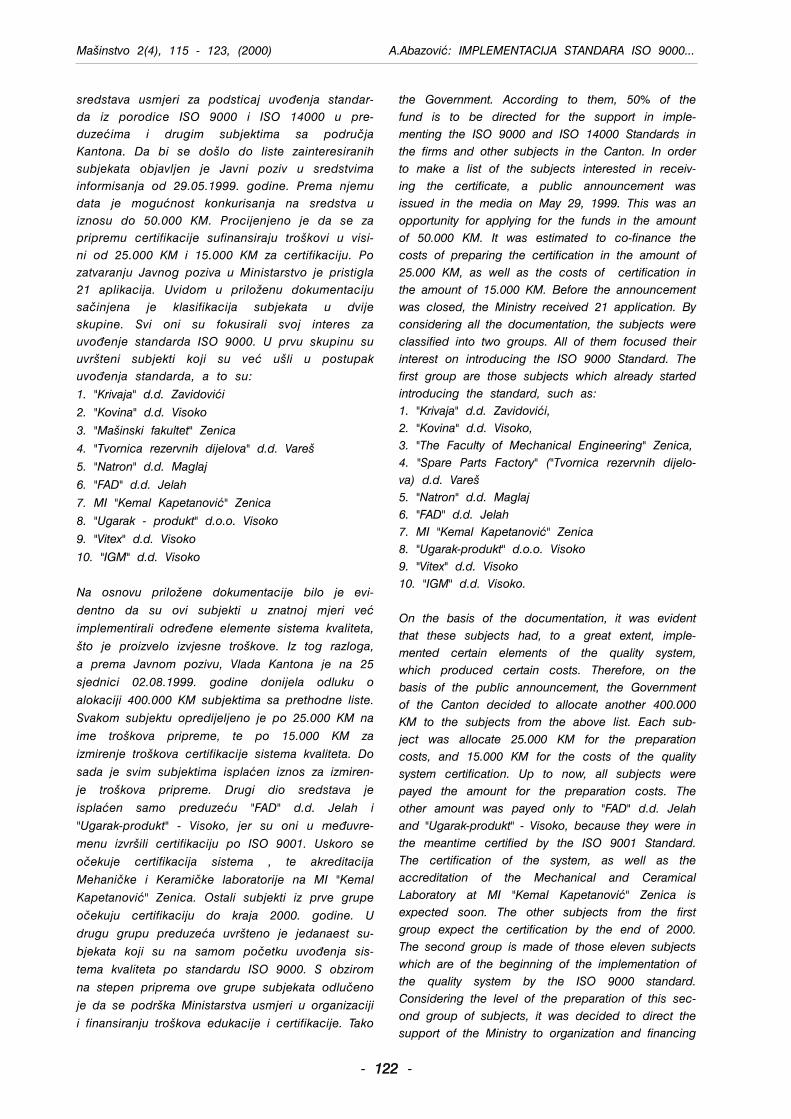
sredstava usmjeri za podsticaj uvo|enja standar-da iz porodice ISO 9000 i ISO 14000 u pre-duzeima i drugim subjektima sa podru~jaKantona. Da bi se dolo do liste zainteresiranihsubjekata objavljen je Javni poziv u sredstvimainformisanja od 29.05.1999. godine. Prema njemudata je mogunost konkurisanja na sredstva uiznosu do 50.000 KM. Procijenjeno je da se zapripremu certifikacije sufinansiraju trokovi u visi-ni od 25.000 KM i 15.000 KM za certifikaciju. Pozatvaranju Javnog poziva u Ministarstvo je pristigla21 aplikacija. Uvidom u prilo`enu dokumentacijusa~injena je klasifikacija subjekata u dvijeskupine. Svi oni su fokusirali svoj interes zauvo|enje standarda ISO 9000. U prvu skupinu suuvrteni subjekti koji su ve uli u postupakuvo|enja standarda, a to su:
1. "Krivaja" d.d. Zavidovii
2. "Kovina" d.d. Visoko
3. "Mainski fakultet" Zenica
4. "Tvornica rezervnih dijelova" d.d. Vare
5. "Natron" d.d. Maglaj
6. "FAD" d.d. Jelah
7. MI "Kemal Kapetanovi" Zenica
8. "Ugarak - produkt" d.o.o. Visoko
9. "Vitex" d.d. Visoko
10. "IGM" d.d. Visoko
Na osnovu prilo`ene dokumentacije bilo je evi-
dentno da su ovi subjekti u znatnoj mjeri ve
implementirali odre|ene elemente sistema kvaliteta,
to je proizvelo izvjesne trokove. Iz tog razloga,
a prema Javnom pozivu, Vlada Kantona je na 25
sjednici 02.08.1999. godine donijela odluku o
alokaciji 400.000 KM subjektima sa prethodne liste.
Svakom subjektu opredijeljeno je po 25.000 KM na
ime trokova pripreme, te po 15.000 KM za
izmirenje trokova certifikacije sistema kvaliteta. Do
sada je svim subjektima isplaen iznos za izmiren-
je trokova pripreme. Drugi dio sredstava je
isplaen samo preduzeu "FAD" d.d. Jelah i
"Ugarak-produkt" - Visoko, jer su oni u me|uvre-
menu izvrili certifikaciju po ISO 9001. Uskoro se
o~ekuje certifikacija sistema , te akreditacija
Mehani~ke i Kerami~ke laboratorije na MI "Kemal
Kapetanovi" Zenica. Ostali subjekti iz prve grupe
o~ekuju certifikaciju do kraja 2000. godine. U
drugu grupu preduzea uvrteno je jedanaest su-
bjekata koji su na samom po~etku uvo|enja sis-
tema kvaliteta po standardu ISO 9000. S obzirom
na stepen priprema ove grupe subjekata odlu~eno
je da se podrka Ministarstva usmjeri u organizaciji
i finansiranju trokova edukacije i certifikacije. Tako
Mainstvo 2(4), 115 - 123, (2000) A.Abazovi: IMPLEMENTACIJA STANDARA ISO 9000...
- 112222 -
the Government. According to them, 50% of thefund is to be directed for the support in imple-menting the ISO 9000 and ISO 14000 Standards inthe firms and other subjects in the Canton. In orderto make a list of the subjects interested in receiv-ing the certificate, a public announcement wasissued in the media on May 29, 1999. This was anopportunity for applying for the funds in the amountof 50.000 KM. It was estimated to co-finance thecosts of preparing the certification in the amount of25.000 KM, as well as the costs of certification inthe amount of 15.000 KM. Before the announcementwas closed, the Ministry received 21 application. Byconsidering all the documentation, the subjects wereclassified into two groups. All of them focused theirinterest on introducing the ISO 9000 Standard. Thefirst group are those subjects which already startedintroducing the standard, such as:1. "Krivaja" d.d. Zavidovii,2. "Kovina" d.d. Visoko,3. "The Faculty of Mechanical Engineering" Zenica,4. "Spare Parts Factory" ("Tvornica rezervnih dijelo-va) d.d. Vare5. "Natron" d.d. Maglaj6. "FAD" d.d. Jelah7. MI "Kemal Kapetanovi" Zenica8. "Ugarak-produkt" d.o.o. Visoko9. "Vitex" d.d. Visoko10. "IGM" d.d. Visoko.
On the basis of the documentation, it was evidentthat these subjects had, to a great extent, imple-mented certain elements of the quality system,which produced certain costs. Therefore, on thebasis of the public announcement, the Governmentof the Canton decided to allocate another 400.000KM to the subjects from the above list. Each sub-ject was allocate 25.000 KM for the preparationcosts, and 15.000 KM for the costs of the qualitysystem certification. Up to now, all subjects werepayed the amount for the preparation costs. Theother amount was payed only to "FAD" d.d. Jelahand "Ugarak-produkt" - Visoko, because they were inthe meantime certified by the ISO 9001 Standard.The certification of the system, as well as theaccreditation of the Mechanical and CeramicalLaboratory at MI "Kemal Kapetanovi" Zenica isexpected soon. The other subjects from the firstgroup expect the certification by the end of 2000.The second group is made of those eleven subjectswhich are of the beginning of the implementation ofthe quality system by the ISO 9000 standard.Considering the level of the preparation of this sec-ond group of subjects, it was decided to direct thesupport of the Ministry to organization and financing
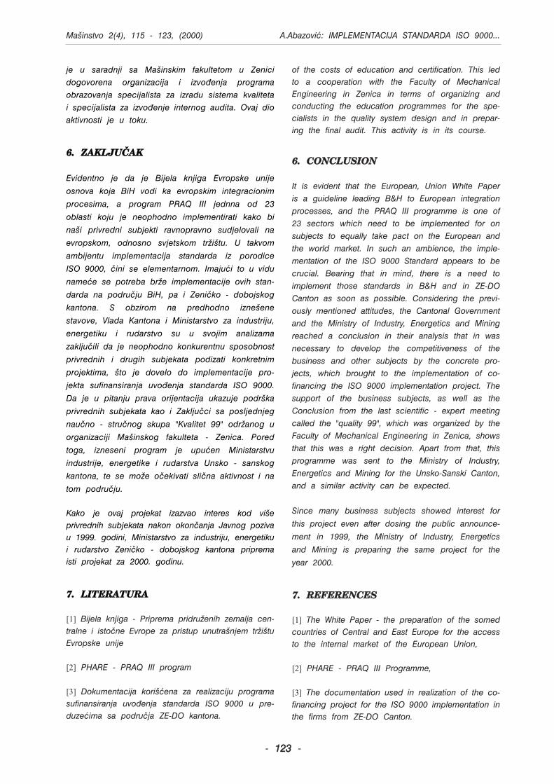
je u saradnji sa Mainskim fakultetom u Zenici
dogovorena organizacija i izvo|enja programa
obrazovanja specijalista za izradu sistema kvaliteta
i specijalista za izvo|enje internog audita. Ovaj dio
aktivnosti je u toku.
6. ZAKLJU^AK
Evidentno je da je Bijela knjiga Evropske unije
osnova koja BiH vodi ka evropskim integracionim
procesima, a program PRAQ III jednna od 23
oblasti koju je neophodno implementirati kako bi
nai privredni subjekti ravnopravno sudjelovali na
evropskom, odnosno svjetskom tr`itu. U takvom
ambijentu implementacija standarda iz porodice
ISO 9000, ~ini se elementarnom. Imajui to u vidu
namee se potreba br`e implementacije ovih stan-
darda na podru~ju BiH, pa i Zeni~ko - dobojskog
kantona. S obzirom na predhodno izneene
stavove, Vlada Kantona i Ministarstvo za industriju,
energetiku i rudarstvo su u svojim analizama
zaklju~ili da je neophodno konkurentnu sposobnost
privrednih i drugih subjekata podizati konkretnim
projektima, to je dovelo do implementacije pro-
jekta sufinansiranja uvo|enja standarda ISO 9000.
Da je u pitanju prava orijentacija ukazuje podrka
privrednih subjekata kao i Zaklju~ci sa posljednjeg
nau~no - stru~nog skupa "Kvalitet 99" odr`anog u
organizaciji Mainskog fakulteta - Zenica. Pored
toga, izneseni program je upuen Ministarstvu
industrije, energetike i rudarstva Unsko - sanskog
kantona, te se mo`e o~ekivati sli~na aktivnost i na
tom podru~ju.
Kako je ovaj projekat izazvao interes kod vieprivrednih subjekata nakon okon~anja Javnog pozivau 1999. godini, Ministarstvo za industriju, energetikui rudarstvo Zeni~ko - dobojskog kantona pripremaisti projekat za 2000. godinu.
7. LITERATURA
[1] Bijela knjiga - Priprema pridru`enih zemalja cen-tralne i isto~ne Evrope za pristup unutranjem tr`ituEvropske unije
[2] PHARE - PRAQ III program
[3] Dokumentacija koriena za realizaciju programasufinansiranja uvo|enja standarda ISO 9000 u pre-duzeima sa podru~ja ZE-DO kantona.
Mainstvo 2(4), 115 - 123, (2000) A.Abazovi: IMPLEMENTACIJA STANDARDA ISO 9000...
- 112233 -
of the costs of education and certification. This ledto a cooperation with the Faculty of MechanicalEngineering in Zenica in terms of organizing andconducting the education programmes for the spe-cialists in the quality system design and in prepar-ing the final audit. This activity is in its course.
6. CONCLUSION
It is evident that the European, Union White Paperis a guideline leading B&H to European integrationprocesses, and the PRAQ III programme is one of23 sectors which need to be implemented for onsubjects to equally take pact on the European andthe world market. In such an ambience, the imple-mentation of the ISO 9000 Standard appears to becrucial. Bearing that in mind, there is a need toimplement those standards in B&H and in ZE-DOCanton as soon as possible. Considering the previ-ously mentioned attitudes, the Cantonal Governmentand the Ministry of Industry, Energetics and Miningreached a conclusion in their analysis that in wasnecessary to develop the competitiveness of thebusiness and other subjects by the concrete pro-jects, which brought to the implementation of co-financing the ISO 9000 implementation project. Thesupport of the business subjects, as well as theConclusion from the last scientific - expert meetingcalled the "quality 99", which was organized by theFaculty of Mechanical Engineering in Zenica, showsthat this was a right decision. Apart from that, thisprogramme was sent to the Ministry of Industry,Energetics and Mining for the Unsko-Sanski Canton,and a similar activity can be expected.
Since many business subjects showed interest for
this project even after dosing the public announce-
ment in 1999, the Ministry of Industry, Energetics
and Mining is preparing the same project for the
year 2000.
7. REFERENCES
[1] The White Paper - the preparation of the somedcountries of Central and East Europe for the accessto the internal market of the European Union,
[2] PHARE - PRAQ III Programme,
[3] The documentation used in realization of the co-financing project for the ISO 9000 implementation inthe firms from ZE-DO Canton.