Embed Size (px)
Citation preview

7/28/2019 ECS2100_ECA3bull
http://slidepdf.com/reader/full/ecs2100eca3bull 1/12
ECS2100 Digital Excitation Sys
ECA-38-09
ECS2100
Excitation Control
Systems
FEATURES• Multi-Microprocessor based ECS2100 Digital Controller
• +0.2% Voltage Regulation Accuracy• Performance response <20 ms
• Redundant Controllers with Independent Supervisory Channel (options)• Six-SCR Power Rectifier Bridges Fixed and Drawer Type (options)
• Multi-Bridge paralleling schemes up to 10,000 Adc
• Provisions for field forcing levels up to 1500 Vdc• High Initial Response Per IEEE 421.2
• Patented Active Current Balance Algorithm• Multiple Excitation Limiters with on-line and off-line settings
• Generator optimization by real-time limiter set point recalibration• Integrated Dual Input Power System Stabilizer IEEE Type 2 (optional)
• Negative Field Forcing for highest system performance• Multiple Operating Modes with Auto-following
• Multiple protection functions with on-line and off-line settings• Programmable input/output terminations• Programmable Sequencing provisions
• Built-in Field Ground Protection (64F)• Interactive Display Panel (IDP-1200) for local and/or remote monitor and control
• ccTools, a sophisticated software configuration program for setup and testing• Continuous self diagnostic capabilities
• Transient event recording and data logging• Incorporates fiber optics for critical signals• Provisions for Field Flashing from Station Service
P. O. BOX 269 HIGHLAND, ILLINOIS, U.S.A. 62249 PHONE 618-654-2341 FAX 618-654-2351
BACKGROUND,HISTORY,
PRODUCT DESCRIPTIOPage 2
FUNCTIONALDESCRIPTION
Pages 3 through 12
Control Channel OptioPages 3 and 4
System OperationPage 5
Hardware/SoftwarePages 6 and 7
Software ControlPages 7 and 8
Limiters and ProtectioPages 8 through 10
Monitoring FunctionsPage 10
Power SectionPages 10 and 11
Control and MaintenanPages 11 and 12
APPLICATIONThe ECS2100 is a multi-microprocessor excitation control system that providesadvanced technology to precisely control, protect, and monitor synchronous
generators, including new and existing applications that are driven by all types of
prime movers, such as steam, gas, hydro, and diesel. Its multifunctional designallows the ECS2100 to operate as a voltage regulator or as a static exciter, providingexcitation currents up to 10,000 Adc on systems ranging from 1 to 1300 MW.

7/28/2019 ECS2100_ECA3bull
http://slidepdf.com/reader/full/ecs2100eca3bull 2/12
ECS2100 Digital Excitation System
BackgroundThe ECS2100 static excitation control systems have
evolved from years of experience that originated withthe original Westinghouse Distribution & Controlsgroup. Under Westinghouse, many products datingback into the 1920’s were developed for the generatorexcitation market. In 1994, Cutler-Hammer purchasedthe Distribution & Controls business from Westinghouseand carried the tradition and expertise to support thissame market. In June of 2006, Basler Electric acquiredCutler-Hammer’s Excitation Control product line tocomplement Basler’s existing DECS product offering.Basler Electric has been committed to the generatorexcitation market since the mid 1960’s and is dedicated
to support this continued effort.
Product History
As part of the acquisition, Basler Electric inherited a
substantial amount of history dating back to the 1920’sthat is associated with the original Westinghouseexcitation products line. The following provides a brief
historical description of the Westinghouse and Cutler-Hammer excitation system now in service in many
power plants.
MGR (Introduced in the late 1980’s)
The MGR (Medium Generator Regulator) was an analogstatic excitation and voltage regulating systems that
covered small and medium size generators in utility,cogeneration, industrial and hydro applications. The
MGR was designed as a replacement for existing
DESCRIPTION
The Basler ECS2100 Digital Excitation System isdesigned to provide digital voltage regulation, control,
protection, and monitoring functions for a synchronousgenerator. The ECS2100 Digital Excitation System is a
multiple microprocessor-based control system. ECS2100uses a digital signal processor for required computa-
tional speed of advanced control functions and algo-rithms and an integrated 32-bit communications control-
ler for implementation of event recording, data logging,
and communications to external control systems and toa user-friendly PC interface for maintenance and analysisfunctions. The ECS2100 can be scaled to generation
units of all sizes with minimal changes except to thepower electronics and the excitation power potential
transformer. A software tool, ccTool, is used to changesettings for the various limiting and protection functions,
download new system firmware, and retrieve diagnosticsinformation.
2
BASLER DIGITAL EXCITATION SYSTEMS - Type ECS2100
Westinghouse voltage regulators and other manufactur-ers' single field regulators. Typically, the MGR provided
excitation levels up to 600 Adc. As an update to theMGR, Basler can provide a “Front End” Digital solution
that utilizes our DECS-400 Digital Excitation ControlSystem. This digital upgrade uses many of the existing
components of the MGR, but it adds many new featuresand functions. Contact Basler Electric for more details
or download the DECS-400 product bulletin (SZF) fromwww.basler.com.
WTA-300B (Introduced in the mid 1990’s)The WTA-300B (Westinghouse Trinastat Amplifier), is the
latest of the WTA family of solid-state analog staticexciter/voltage regulators which were standard equip-
ment on large utility and industrial generators typicallysized greater than 100,000 kVA. The first WTAs were
introduced in the mid 1960’s. Typically, the WTA-300B
was utilized for excitation currents greater than 500 Adc.WDR-2000 (Introduced in the early 1990’s)
The WDR-2000 (Westinghouse Digital Regulator) wasWestinghouse’s first microprocessor designed excitationsystem. Primarily, it was applied on medium to largegenerators requiring 1000 to 10,000 Adc of excitation.Today, the WDR-2000 can be retrofitted with the latesttechnology by replacing the WDR rack module with adrop-in ECS-RW. The ECS-RW provides advanced
communication capabilities and many of the samefeatures and functions as specified in this product
bulletin. Contact Basler Electric for more details.
The Basler system consists of one or more thyristorpower converters, each with its own digital firing con-
trol. A single converter or multiple converters operatewith single-channel or multi-channel control logic for
increased reliability. Operator control can be providedthrough a single-cable interconnection to a local and/or
remote Interactive Display Panel (IDP-1200), interface toPLC, SCADA, or plant DCS (Distributed Control Sys-
tem), or traditional discrete switches and meters.
Power to the ECS2100 can be supplied via a power
potential transformer (PPT) from the generator terminals. A field flashing option will be added for black start when
the generator terminals are used for the excitation powersource. Alternately, power to the ECS2100 Digital
Excitation System can be taken from a reliable three-phase, 50 or 60 Hz station auxiliary source or from a
PMG (Permanent Magnet Generator) with a frequencyup to 420 Hz.
7/28/2019 ECS2100_ECA3bull
http://slidepdf.com/reader/full/ecs2100eca3bull 3/12
ECS2100 Digital Excitation Sys
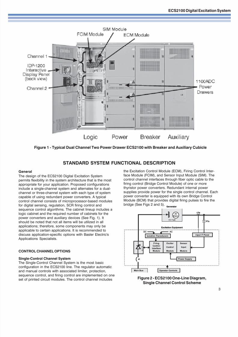
Figure 1 - Typical Dual Channel Two Power Drawer ECS2100 with Breaker and Auxiliary Cubicle
3
STANDARD SYSTEM FUNCTIONAL DESCRIPTION
General
The design of the ECS2100 Digital Excitation Systempermits flexibility in the system architecture that is the most
appropriate for your application. Proposed configurationsinclude a single-channel system and alternates for a dual-
channel or three-channel system with each type of systemcapable of using redundant power converters. A typical
control channel consists of microprocessor-based modulesfor digital sensing, regulation, SCR firing control and
sequence control algorithms. The cabinet lineup includes a
logic cabinet and the required number of cabinets for thepower converters and auxiliary devices (See Fig. 1). It
should be noted that not all items will be utilized in allapplications; therefore, some components may only be
applicable to certain applications. It is recommended to
discuss application-specific options with Basler Electric's Applications Specialists.
CONTROL CHANNEL OPTIONS
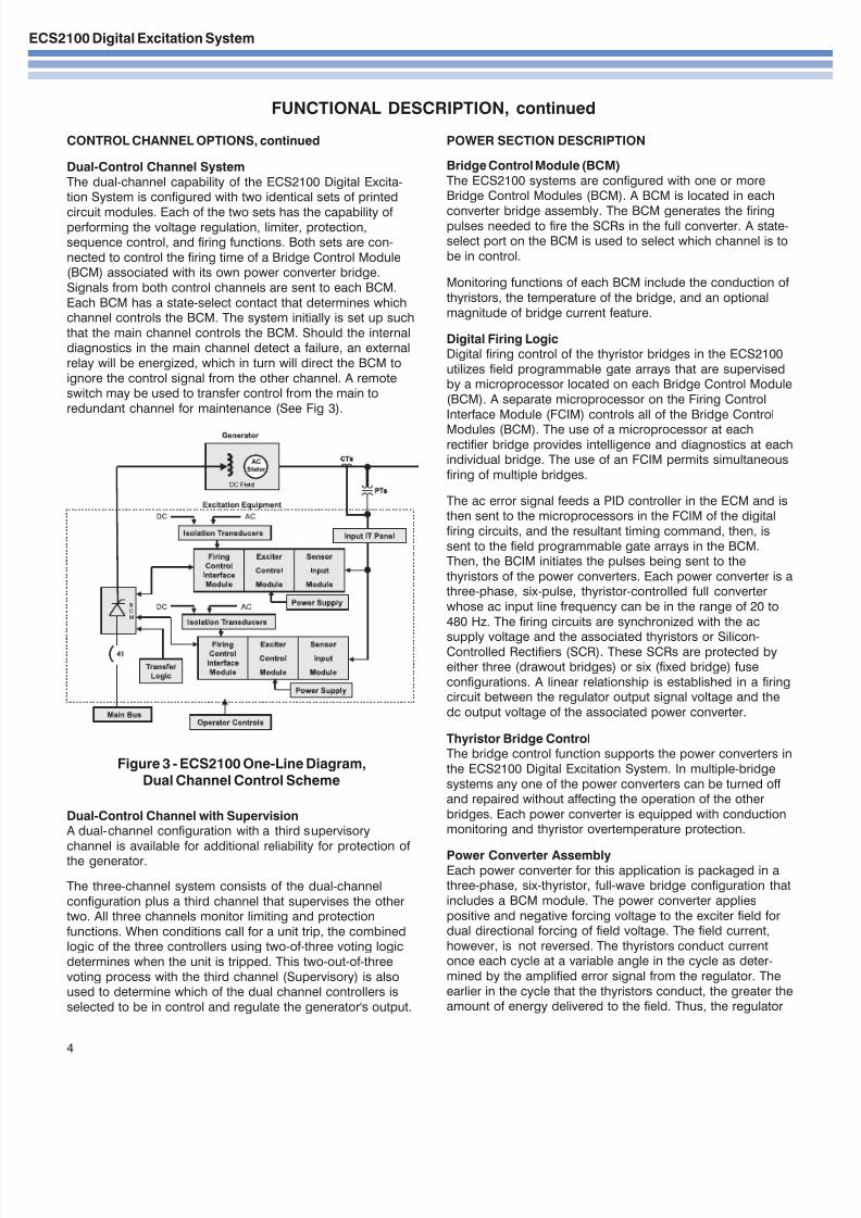
Single-Control Channel SystemThe Single-Control Channel System is the most basic
configuration in the ECS2100 line. The regulator automaticand manual controls with associated limiter, protection,
sequence control, and firing control are implemented on one
set of printed circuit modules. The control channel includes
the Excitation Control Module (ECM), Firing Control Inter-face Module (FCIM), and Sensor Input Module (SIM). The
control channel interfaces through fiber optic cable to the
firing control (Bridge Control Module) of one or morethyristor power converters. Redundant internal power
supplies provide power for the single control channel. Eachpower converter is equipped with its own Bridge Control
Module (BCM) that provides digital firing pulses to fire the
bridge (See Figs 2 and 5).
Figure 2 - ECS2100 One-Line Diagram,
Single Channel Control Scheme
7/28/2019 ECS2100_ECA3bull
http://slidepdf.com/reader/full/ecs2100eca3bull 4/12
ECS2100 Digital Excitation System
FUNCTIONAL DESCRIPTION, continued
4
CONTROL CHANNEL OPTIONS, continued
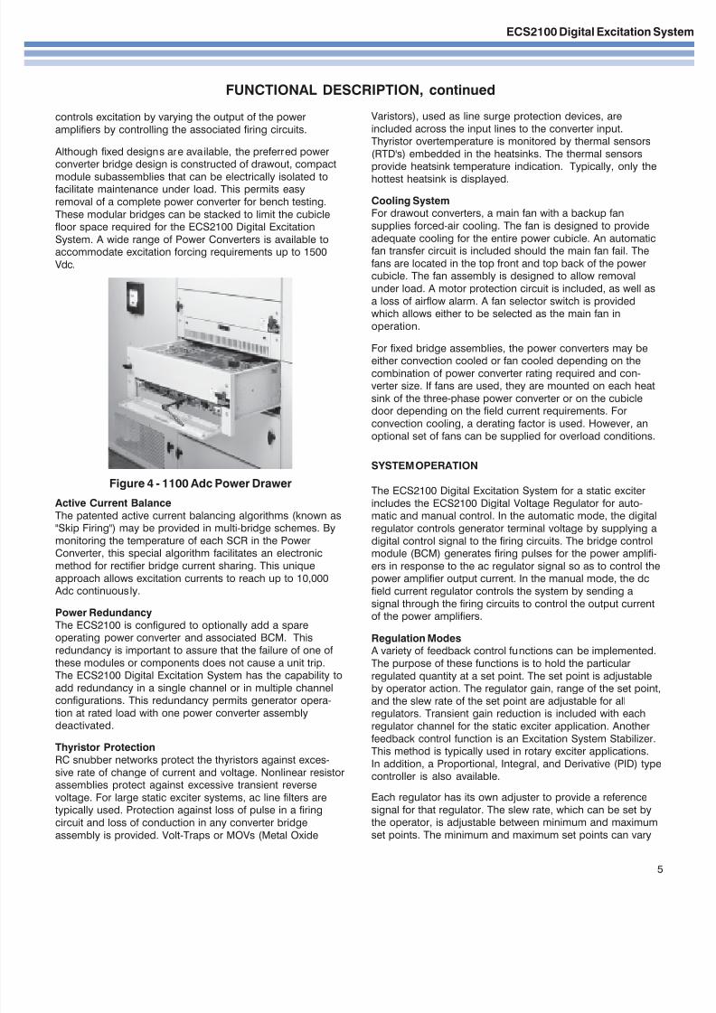
Dual-Control Channel System
The dual-channel capability of the ECS2100 Digital Excita-tion System is configured with two identical sets of printed
circuit modules. Each of the two sets has the capability of performing the voltage regulation, limiter, protection,sequence control, and firing functions. Both sets are con-
nected to control the firing time of a Bridge Control Module(BCM) associated with its own power converter bridge.
Signals from both control channels are sent to each BCM.
Each BCM has a state-select contact that determines whichchannel controls the BCM. The system initially is set up such
that the main channel controls the BCM. Should the internaldiagnostics in the main channel detect a failure, an external
relay will be energized, which in turn will direct the BCM to
ignore the control signal from the other channel. A remoteswitch may be used to transfer control from the main to
redundant channel for maintenance (See Fig 3).
Dual-Control Channel with Supervision A dual-channel configuration with a third supervisory
channel is available for additional reliability for protection of the generator.
The three-channel system consists of the dual-channel
configuration plus a third channel that supervises the othertwo. All three channels monitor limiting and protection
functions. When conditions call for a unit trip, the combinedlogic of the three controllers using two-of-three voting logic
determines when the unit is tripped. This two-out-of-three
voting process with the third channel (Supervisory) is alsoused to determine which of the dual channel controllers is
selected to be in control and regulate the generator's output.
Figure 3 - ECS2100 One-Line Diagram,Dual Channel Control Scheme
POWER SECTION DESCRIPTION
Bridge Control Module (BCM)
The ECS2100 systems are configured with one or moreBridge Control Modules (BCM). A BCM is located in each
converter bridge assembly. The BCM generates the firingpulses needed to fire the SCRs in the full converter. A state-select port on the BCM is used to select which channel is to
be in control.
Monitoring functions of each BCM include the conduction of
thyristors, the temperature of the bridge, and an optional
magnitude of bridge current feature.
Digital Firing LogicDigital firing control of the thyristor bridges in the ECS2100
utilizes field programmable gate arrays that are supervisedby a microprocessor located on each Bridge Control Module
(BCM). A separate microprocessor on the Firing Control
Interface Module (FCIM) controls all of the Bridge Control
Modules (BCM). The use of a microprocessor at eachrectifier bridge provides intelligence and diagnostics at eachindividual bridge. The use of an FCIM permits simultaneous
firing of multiple bridges.
The ac error signal feeds a PID controller in the ECM and isthen sent to the microprocessors in the FCIM of the digital
firing circuits, and the resultant timing command, then, is
sent to the field programmable gate arrays in the BCM.Then, the BCIM initiates the pulses being sent to the
thyristors of the power converters. Each power converter is athree-phase, six-pulse, thyristor-controlled full converter
whose ac input line frequency can be in the range of 20 to
480 Hz. The firing circuits are synchronized with the ac
supply voltage and the associated thyristors or Silicon-Controlled Rectifiers (SCR). These SCRs are protected byeither three (drawout bridges) or six (fixed bridge) fuse
configurations. A linear relationship is established in a firingcircuit between the regulator output signal voltage and the
dc output voltage of the associated power converter.
Thyristor Bridge ControlThe bridge control function supports the power converters in
the ECS2100 Digital Excitation System. In multiple-bridge
systems any one of the power converters can be turned off and repaired without affecting the operation of the other
bridges. Each power converter is equipped with conductionmonitoring and thyristor overtemperature protection.
Power Converter AssemblyEach power converter for this application is packaged in athree-phase, six-thyristor, full-wave bridge configuration that
includes a BCM module. The power converter applies
positive and negative forcing voltage to the exciter field fordual directional forcing of field voltage. The field current,
however, is not reversed. The thyristors conduct currentonce each cycle at a variable angle in the cycle as deter-
mined by the amplified error signal from the regulator. The
earlier in the cycle that the thyristors conduct, the greater theamount of energy delivered to the field. Thus, the regulator
7/28/2019 ECS2100_ECA3bull
http://slidepdf.com/reader/full/ecs2100eca3bull 5/12
ECS2100 Digital Excitation Sys
FUNCTIONAL DESCRIPTION, continued
5
SYSTEM OPERATION
The ECS2100 Digital Excitation System for a static exciter
includes the ECS2100 Digital Voltage Regulator for auto-matic and manual control. In the automatic mode, the digital
regulator controls generator terminal voltage by supplying adigital control signal to the firing circuits. The bridge controlmodule (BCM) generates firing pulses for the power amplifi-
ers in response to the ac regulator signal so as to control thepower amplifier output current. In the manual mode, the dc
field current regulator controls the system by sending a
signal through the firing circuits to control the output currentof the power amplifiers.
Regulation Modes A variety of feedback control functions can be implemented.
The purpose of these functions is to hold the particular
regulated quantity at a set point. The set point is adjustableby operator action. The regulator gain, range of the set point,
and the slew rate of the set point are adjustable for all
regulators. Transient gain reduction is included with eachregulator channel for the static exciter application. Another
feedback control function is an Excitation System Stabilizer.This method is typically used in rotary exciter applications.
In addition, a Proportional, Integral, and Derivative (PID) typecontroller is also available.
Each regulator has its own adjuster to provide a reference
signal for that regulator. The slew rate, which can be set bythe operator, is adjustable between minimum and maximum
set points. The minimum and maximum set points can vary
controls excitation by varying the output of the power
amplifiers by controlling the associated firing circuits.
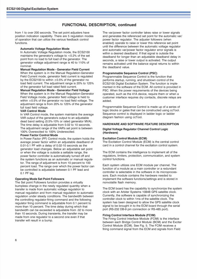
Although fixed designs are available, the preferred powerconverter bridge design is constructed of drawout, compact
module subassemblies that can be electrically isolated tofacilitate maintenance under load. This permits easy
removal of a complete power converter for bench testing.
These modular bridges can be stacked to limit the cubiclefloor space required for the ECS2100 Digital Excitation
System. A wide range of Power Converters is available toaccommodate excitation forcing requirements up to 1500
Vdc.
Active Current Balance
The patented active current balancing algorithms (known as
"Skip Firing") may be provided in multi-bridge schemes. Bymonitoring the temperature of each SCR in the PowerConverter, this special algorithm facilitates an electronic
method for rectifier bridge current sharing. This unique
approach allows excitation currents to reach up to 10,000 Adc continuously.
Power Redundancy
The ECS2100 is configured to optionally add a spareoperating power converter and associated BCM. This
redundancy is important to assure that the failure of one of
these modules or components does not cause a unit trip.The ECS2100 Digital Excitation System has the capability to
add redundancy in a single channel or in multiple channelconfigurations. This redundancy permits generator opera-
tion at rated load with one power converter assemblydeactivated.
Thyristor Protection
RC snubber networks protect the thyristors against exces-
sive rate of change of current and voltage. Nonlinear resistorassemblies protect against excessive transient reverse
voltage. For large static exciter systems, ac line filters aretypically used. Protection against loss of pulse in a firing
circuit and loss of conduction in any converter bridge
assembly is provided. Volt-Traps or MOVs (Metal Oxide
Varistors), used as line surge protection devices, are
included across the input lines to the converter input.Thyristor overtemperature is monitored by thermal sensors
(RTD's) embedded in the heatsinks. The thermal sensorsprovide heatsink temperature indication. Typically, only the
hottest heatsink is displayed.
Cooling SystemFor drawout converters, a main fan with a backup fan
supplies forced-air cooling. The fan is designed to provide
adequate cooling for the entire power cubicle. An automaticfan transfer circuit is included should the main fan fail. The
fans are located in the top front and top back of the powercubicle. The fan assembly is designed to allow removal
under load. A motor protection circuit is included, as well as
a loss of airflow alarm. A fan selector switch is providedwhich allows either to be selected as the main fan in
operation.
For fixed bridge assemblies, the power converters may beeither convection cooled or fan cooled depending on the
combination of power converter rating required and con-verter size. If fans are used, they are mounted on each heat
sink of the three-phase power converter or on the cubicledoor depending on the field current requirements. For
convection cooling, a derating factor is used. However, an
optional set of fans can be supplied for overload conditions.
Figure 4 - 1100 Adc Power Drawer
7/28/2019 ECS2100_ECA3bull
http://slidepdf.com/reader/full/ecs2100eca3bull 6/12
ECS2100 Digital Excitation System
FUNCTIONAL DESCRIPTION, continued
6
The var/power factor controller takes raise or lower signals
and generates the referenced set point for the automatic var/power factor regulator. The adjuster followers (when
enabled) operate to raise or lower this reference set point
until the difference between the automatic voltage regulator
and automatic var/power factor regulator error signals iswithin a desired deadband. If that signal is outside thedeadband for longer than an adjustable deadband delay in
seconds, a raise or lower output is activated. The outputremains activated until the balance signal returns to within
the deadband value.
Programmable Sequence Control (PSC)
Programmable Sequence Control is the function thatperforms startup, running, and shutdown control of the
ECS2100 Digital Excitation System. The function is imple-mented in the software of the ECM. All control is provided in
PSC. When the power requirements of the devices being
operated, such as the 41A device, require them or when a
customer interface requires dry contacts, discrete relays areadded.
Programmable Sequence Control is made up of a series of logic blocks or gates that can be constructed using ccTool.
Sequence control is displayed in ladder logic or ladderdiagram fashion using ccTool.
HARDWARE AND SOFTWARE FEATURE DESCRIPTION
Digital Voltage Regulator Channel Control Logic
(Hardware)
Excitation Control Module (ECM)The Excitation Control Module (ECM) is the central control
card in a control channel for the excitation control system.
The ECM contains the intelligence to implement all of theregulators, limiters, protection, communication, and system
control functions.
Each system utilizes one ECM module per channel. The
function of a module as a main controller or a redundantcontroller is selectable in the software in its microproces-
sors. Each module contains the hardware needed toimplement the software functions/settings and is stored in
nonvolatile flash memory.
The ECM board has the capability to synchronize the systemclock with an Arbiter Systems 1084B GPS satellite clock.
Currently, the software is capable of synchronizing thecontroller clock to within 1ms of the satellite clock. The
system has been designed to allow the GPS satellite clock
signal to be brought in to the ECM board through the serialport (RS-232 DB-9 pin connection or RS-485 port).
Firing Control Interface Module (FCIM)
The Firing Control Interface Module (FCIM) is the interfacebetween each Bridge Control Module (BCM) and the Exciter
Control Module (ECM). See Fig. 5. The FCIM receives a
firing command signal from the ECM and signals from Field
from 1 to over 200 seconds. The set point adjusters have
position indication capability. There are 5 regulation modesof operation that can utilize the various feedback control
functions.
Automatic Voltage Regulation ModeIn Automatic Voltage Regulation mode, the ECS2100
maintains the generator's voltage to <0.2% of the setpoint from no load to full load of the generator. The
generator voltage adjustment range is 40 to 110% of
nominal.Manual Regulation Mode - Generator Field Current
When the system is in the Manual Regulation-GeneratorField Current mode, generator field current is regulated
by the ECS2100 to within ±0.5% of the generator noload field current. The adjustment range is 20% to 125%
of the generator full load rated field current.
Manual Regulation Mode - Generator Field VoltageWhen the system is in the Manual Regulation-Generator
Field Voltage mode, generator field voltage is held towithin ±0.5% of the generator no load field voltage. The
adjustment range is from 20% to 125% of the generator
full load field voltage. VAR Control Mode
In VAR Control mode, the system maintains the averageVAR output of the generators output to an adjustable
dead band setting (0.5%-10% or rated generator MVA).
The time delay is adjustable from 0.02 to 10 seconds.The adjustment range of the VAR's set point is between
100% Overexcited to 100% Underexcited.Power Factor Control Mode
In Power Factor (PF) Control mode, the system holds theaverage power factor within an adjustable deadband of
0.01-0.1 PF with a delay of 0.02-10 seconds as thegenerator load changes. Below an adjustable set pointor when the voltage is outside a settable range, the
power factor controller is automatically turned off andthe system functions as an automatic or manual regula-
tor. The range of adjustment is from 10 percent to 100
percent load. The range over which the power factor canbe controlled is adjustable between 0.1 PF lead and
0.1 PF lag.
Operating Mode Set Point Followers
The Set point Followers function provides a virtually
bumpless change in the newly regulated quantity when atransfer is made from automatic voltage regulation to
manual regulation and from manual regulation to automatic
regulation under steady conditions. The bandwidth betweenthe controlling regulator-firing command and the following
regulator firing command is adjustable from 0.1 percent tomore than 10 percent. The time delay during which that
bandwidth can be exceeded is adjustable from .02 to morethan 10 seconds. During transients, the transfer may be
made from one regulator to a second one even if thattransfer will result in a bump.
7/28/2019 ECS2100_ECA3bull
http://slidepdf.com/reader/full/ecs2100eca3bull 7/12
ECS2100 Digital Excitation Sys
7
FUNCTIONAL DESCRIPTION, continued
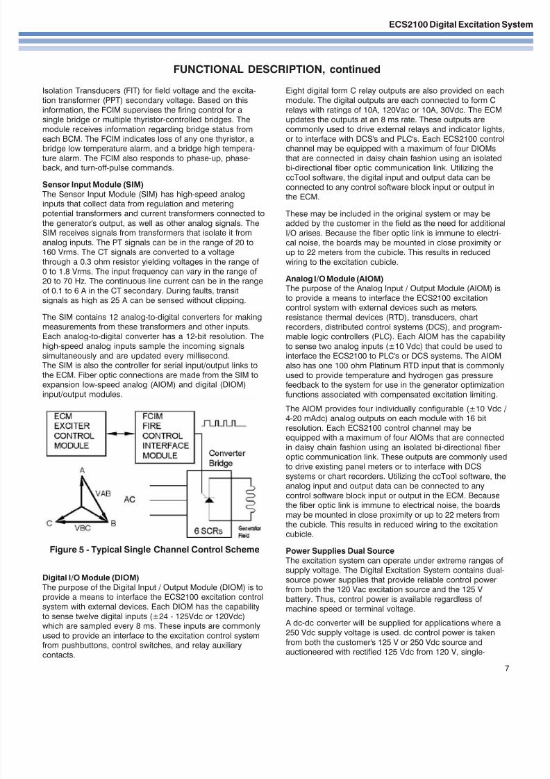
Figure 5 - Typical Single Channel Control Scheme
Isolation Transducers (FIT) for field voltage and the excita-tion transformer (PPT) secondary voltage. Based on this
information, the FCIM supervises the firing control for asingle bridge or multiple thyristor-controlled bridges. The
module receives information regarding bridge status from
each BCM. The FCIM indicates loss of any one thyristor, abridge low temperature alarm, and a bridge high tempera-
ture alarm. The FCIM also responds to phase-up, phase-back, and turn-off-pulse commands.
Sensor Input Module (SIM)
The Sensor Input Module (SIM) has high-speed analoginputs that collect data from regulation and metering
potential transformers and current transformers connected to
the generator's output, as well as other analog signals. TheSIM receives signals from transformers that isolate it from
analog inputs. The PT signals can be in the range of 20 to160 Vrms. The CT signals are converted to a voltage
through a 0.3 ohm resistor yielding voltages in the range of
0 to 1.8 Vrms. The input frequency can vary in the range of 20 to 70 Hz. The continuous line current can be in the range
of 0.1 to 6 A in the CT secondary. During faults, transitsignals as high as 25 A can be sensed without clipping.
The SIM contains 12 analog-to-digital converters for making
measurements from these transformers and other inputs.Each analog-to-digital converter has a 12-bit resolution. The
high-speed analog inputs sample the incoming signals
simultaneously and are updated every millisecond.The SIM is also the controller for serial input/output links to
the ECM. Fiber optic connections are made from the SIM toexpansion low-speed analog (AIOM) and digital (DIOM)
input/output modules.
Digital I/O Module (DIOM)
The purpose of the Digital Input / Output Module (DIOM) is toprovide a means to interface the ECS2100 excitation control
system with external devices. Each DIOM has the capability
to sense twelve digital inputs (±24 - 125Vdc or 120Vdc)which are sampled every 8 ms. These inputs are commonly
used to provide an interface to the excitation control systemfrom pushbuttons, control switches, and relay auxiliary
contacts.
Eight digital form C relay outputs are also provided on eachmodule. The digital outputs are each connected to form C
relays with ratings of 10A, 120Vac or 10A, 30Vdc. The ECMupdates the outputs at an 8 ms rate. These outputs are
commonly used to drive external relays and indicator lights,
or to interface with DCS's and PLC's. Each ECS2100 controlchannel may be equipped with a maximum of four DIOMs
that are connected in daisy chain fashion using an isolatedbi-directional fiber optic communication link. Utilizing the
ccTool software, the digital input and output data can be
connected to any control software block input or output inthe ECM.
These may be included in the original system or may beadded by the customer in the field as the need for additional
I/O arises. Because the fiber optic link is immune to electri-
cal noise, the boards may be mounted in close proximity orup to 22 meters from the cubicle. This results in reduced
wiring to the excitation cubicle.
Analog I/O Module (AIOM)The purpose of the Analog Input / Output Module (AIOM) is
to provide a means to interface the ECS2100 excitationcontrol system with external devices such as meters,
resistance thermal devices (RTD), transducers, chart
recorders, distributed control systems (DCS), and program-mable logic controllers (PLC). Each AIOM has the capability
to sense two analog inputs (±10 Vdc) that could be used tointerface the ECS2100 to PLC's or DCS systems. The AIOM
also has one 100 ohm Platinum RTD input that is commonly
used to provide temperature and hydrogen gas pressurefeedback to the system for use in the generator optimization
functions associated with compensated excitation limiting.
The AIOM provides four individually configurable (±10 Vdc /4-20 mAdc) analog outputs on each module with 16 bit
resolution. Each ECS2100 control channel may beequipped with a maximum of four AIOMs that are connected
in daisy chain fashion using an isolated bi-directional fiberoptic communication link. These outputs are commonly used
to drive existing panel meters or to interface with DCS
systems or chart recorders. Utilizing the ccTool software, theanalog input and output data can be connected to any
control software block input or output in the ECM. Becausethe fiber optic link is immune to electrical noise, the boards
may be mounted in close proximity or up to 22 meters from
the cubicle. This results in reduced wiring to the excitationcubicle.
Power Supplies Dual Source
The excitation system can operate under extreme ranges of supply voltage. The Digital Excitation System contains dual-
source power supplies that provide reliable control powerfrom both the 120 Vac excitation source and the 125 V
battery. Thus, control power is available regardless of
machine speed or terminal voltage.
A dc-dc converter will be supplied for applications where a
250 Vdc supply voltage is used. dc control power is taken
from both the customer's 125 V or 250 Vdc source andauctioneered with rectified 125 Vdc from 120 V, single-
7/28/2019 ECS2100_ECA3bull
http://slidepdf.com/reader/full/ecs2100eca3bull 8/12
ECS2100 Digital Excitation System
FUNCTIONAL DESCRIPTION, continued
8
Control firing of the thyristor is implemented when theexcitation system provides a de-excitation signal, typically
when device 41A, the ac supply breaker, is opened. Voltagefiring triggers the thyristor when the field voltage exceeds a
preset negative voltage value. Feedback to the excitationsystem is provided when current is present in the DX module. A current sensing circuit in the module provides a logic
signal to the excitation system whenever the current in theDX exceeds a minimum preset level.
Crowbar Module (CB)
The Crowbar module (CB) protects the generator field and
exciter power converter from excessive high positive fieldvoltages. Generator pole slip is a source of positive high
voltage. The Crowbar self-triggers any time a high voltageoccurs. The system automatically recovers once the voltage
starts to go negative.
Since the power converter thyristors are likely to be phased
on when the Crowbar operates, a resistor is placed in serieswith the module to limit the bridge current and provide apole-slip current path. Feedback to the excitation system is
provided when current is present in the Crowbar.
Field Flashing (Optional)Field flashing is required when the static exciter receives all
of its energy supply from the machine terminals and the
machine terminal voltage is zero at startup. It is necessary toflash the machine field to raise the machine terminal voltage
to a suitable level that is sufficient for the static exciter tobegin to build up the machine voltage.
In order to ensure positive buildup of the ac generator
voltage on startup, a reliable dc source of power is required
for momentary field flashing. This source of power is appliedmomentarily to the generator field during startup by means of
contacts on the field flash contactor. Field flashing after thea-c contactor closes by automatic or manual implementation,
which may be supplied as an option. In manual if the
operator releases the switch, the momentary action permitsthe field to be disconnected from the dc source. The field
flashing circuit includes a timer to prevent overflashing thefield and a phase-up circuit that minimizes the load on the
station battery source. The field flash is turned off wheneither the terminal voltage builds up or the field current
exceeds a settable minimum value. The range of settings is
from 1 percent to 100 percent of no-load field current.
Optionally, an ac, single-phase field-flashing source can beused. In that case a rectifier circuit is added to the assembly.
SOFTWARE CONTROL FUNCTIONS
Reactive Compensation
Reactive compensation, either droop or rise, is included withthe ECS2100 system. These functions modify generator
voltage by regulator action to compensate for the impedancedrop from the machine terminals to a fixed point in the
system. Action is accomplished by inserting into the regulator
a reference voltage equivalent to the settable impedance
phase ac taken from the secondary of the excitation trans-
former.
Generator Field Ground Detection
A ground in the field of a synchronous machine should bedetected since the occurrence of a second ground might
short circuit part of the field winding, and the resultantunbalance and vibration may damage the machine.
The function of the exciter ground detector panel is to detect
a ground current flowing from the machine dc field windingto the grounded machine shaft. The ground detector con-
tinuously monitors the machine field and detects groundcurrents ranging from 0.1 mA to 15 mA. A remote alarm is
available for annunciation whenever a ground is detected.
Provision is also made for checking the operation of theground current sensing circuitry by applying a "simulated
ground" to the PC card. The ground detector panel may beapplied to brush excitation systems at rated generator field
voltages up to 1,250 Vdc.
Rapid De-Excitation A dc field breaker is not required with the ECS2100. Con-
sequently, there is no need for a field discharge resistor ordc field breaker. An ac supply contactor or drawout circuit
breaker, electrically operated with six (6) auxiliary contacts,
will be supplied. The exciter power amplifier is a full con-verter (with thyristors in all legs of the three-phase bridge)
with the ability to force down excitation quickly. The field isde-excited by phasing back the firing pulses to the static
exciter amplifier. This action causes stored energy in thefield to be inverted back to the source, which quickly
reduces the field excitation to zero. Upon opening the ac
field contactor, the remaining field energy will be dissipatedvery rapidly in a nonlinear resistor permanently connected
across the field. Under emergencies when the ac fieldcontactor is opened without de-exciting the field, the field
current is discharged through the last two conducting
thyristors or the nonlinear resistor.
In larger static excitation systems, rapid de-excitation isaccomplished by a combination of electronically inverting
the field voltage and triggering the DX module that shorts thefield through a discharge resistor. The energy stored in the
field is dissipated quickly in the discharge resistor that
reduces the field excitation to zero. The ac field breaker isthen opened to complete the shutdown.
De-excitation Module (DX)The DX module is a thyristor-controlled circuit that providesan alternate path for the generator field current when the
normal path is not available. The normal path is through thePPT, 41A-supply breaker, and the generator field. Should
this path be interrupted, the DX circuit provides the safe
alternate path to dissipate the field energy. To provide thealternate path, the DX thyristor is triggered by a control
signal and/or excessive negative field voltage.

7/28/2019 ECS2100_ECA3bull
http://slidepdf.com/reader/full/ecs2100eca3bull 9/12
ECS2100 Digital Excitation Sys
FUNCTIONAL DESCRIPTION, continued
9
drop time's reactive current. Three types of reactive compen-
sation are available with the ECS2100.• Generator Reactive Current Compensation - Using One Set of
CTs• Generator Cross-Current Compensation - Using Two Sets of
CTs (Optional)• Line Drop Compensation Using a Line CT - Responds to both
Resistive and Reactive currents (Optional)
Power System Stabilizer (Optional)The Power System Stabilizer (PSS) provides a supplemen-
tary control signal input to a synchronous machine voltageregulator that improves system dynamic performance. The
stabilizing signal provides positive damping of the electro-
mechanical oscillations that occur as a result of systemdisturbances. Without supplementary control, a continuously
acting voltage regulator can contribute negative damping tosystem swings, and these oscillations may be sustained or
may even increase in amplitude.
The ECS2100 utilizes a predefined IEEE Type 2 "Integral of Accelerating Power" Dual Input PSS (power and frequency)power system stabilizer algorithm. The function produces a
stabilizing signal derived from two inputs: the deviation insynchronous machine speed and electrical power. The
polarity of the signal is in the direction to increase excitationfor terminal frequency deviations above normal frequency.
This dual input PSS includes a ramp-tracking filter: one or
two stages of high pass (washout) filters, and two or threelead-lag stages. Ramping output limiters are included to
minimize the adverse effects of the PSS on system voltage.The Type 2 PSS requires inputs from three line CTs to
achieve the best accuracy. The PSS also incorporates a low
power threshold and will automatically disable the PSS
function when the generators power drop below a predeter-mined level.
LIMITERSThe purpose of limiters is to take away control from any of the
regulators, either manual or auto, then regulate the particularquantity at the pickup point of the limiter. The limiters provide
an alternate feedback control loop to the regulators, and
each limiter is provided with its own adjustable gain, adjust-able transient gain reduction, or damping algorithm as
needed to provide stable loop operation when the limiter isin control. Limiters operate whether the unit is in automatic or
manual regulation modes.
All limiters have alarms associated with them. The first alarmis generated when the pickup has been exceeded. A second
alarm, for limiters with time delays, is generated after the
limiter has timed out. A third alarm is generated when thelimiter has taken control from the regulator.
Minimum Excitation Limiter- Steady State Stability Limit
(MEL)The Minimum Excitation Limiter (MEL) is based on generator
stability. The limiter keeps the operating point of the genera-tor within adjustable MW and Mvar curves. The operating
curve, in terms of MW and Mvar will vary proportionally to the
square of the generator terminal voltage. The shape of the
MW and Mvar operating curves is constructed in a piece-
wise-linear fashion made up of five straight-line segments.Both Summing Point and Takeover style limiter is available
with the MEL.
Under Excitation Limiter- Generator Capability Curve(UEL)
The Under Excitation Limiter (UEL) prevents excitationreduction in the ac generator to levels that would result in
damage to the generator while it is operating in an
underexcited mode. The UEL is based on the generatorcapability curve. The limiter keeps the operating point of the
generator within adjustable MW and Mvar curves. Theshapes of the MW and Mvar operating curves are con-
structed in a piecewise-linear fashion made up of five
straight-line segments. The inputs to the limiter are takenfrom machine potential and current transformers. The limiter
output auctioneers against the voltage sensing signal outputin an auctioneering function for control of the power amplifi-
ers. The control of the power amplifiers by the limiterprevents the auto or manual regulator elements from
decreasing machine excitation to levels below the desired
set characteristic value. Both Suming Point and Takeoverstyle limiter is available with the UEL.
Note: The following pickup modification (recalibration)
functions are available as options to the UEL:
Hydrogen Gas Pressure Recalibration for UEL (Optional)Hydrogen Gas Pressure Recalibration modifies the UEL
operating curve. The curve varies as a function of thegenerator hydrogen pressure and is reduced as the
hydrogen pressure is reduced. The system receives either
a 4-20 mA signal or a ±10 V signal.
Temperature Recalibration for UEL (Optional)Temperature Recalibration modifies the UEL operatingcurve. The modified curve varies as a function of the
generator temperature measured by an RTD. The curve is
proportional to the temperature.
Over Excitation Limiter (OEL)
The Over Excitation Limiter (OEL) acts through the regulatorto return the value of excitation to a preset value after
an adjustable time delay during which overexcitation ispermitted for field forcing. The limiter operates on an
inverse time characteristic that permits lower values of
overexcitation for longer time intervals and limits highervalues of over-excitation for shorter time intervals. This
limiter's output auctioneers with the output of theauctioneering function in a signal mixer such that reduced
excitation is sent to the firing circuit. The Over Excitation
Limiter keeps the generator field current or voltage below adesired value of field voltage or field current that is
adjustable. This limiter functions with the InstantaneousLimiter to provide a two step operation. The first operation
is the instantaneous limiter. The second operation is the
time-delayed limiter.
The OEL provides a "memory" of the time-dependent nature
of the residual and cumulative effects of rotor heating. If the
7/28/2019 ECS2100_ECA3bull
http://slidepdf.com/reader/full/ecs2100eca3bull 10/12
ECS2100 Digital Excitation System
FUNCTIONAL DESCRIPTION, continued
10
desired line voltage. The limiter uses a selectable fixed
time delay.Generator Line Current Limiter
The Generator Line Current Limiter keeps the generatorline current below a desired level. The limiter is disabled
when the power factor is near unity between 0.99 PF lag
and 0.99 PF lead. The limiter is bidirectional. When thegenerator is operating overexcited, this limiter reduces the
field current. When the generator is operatingunderexcited, the limiter raises the field current. The
operation of the limiter occurs following a fixed time delayafter the current has exceeded the pickup point. When the
limiter is operating, it regulates the generator line current
to within ±1.0% provided that the power factor is eitherless than 0.99 pf lead or less than 0.99 PF lag.
Hydrogen Gas Pressure Recalibration for GeneratorLine Current Limiter (Optional)
Hydrogen Gas Pressure Recalibration modifies the Line
Current Limiter operating curve. The curve will be varied
as a function of the generator hydrogen pressure and isreduced as the hydrogen pressure is being reduced. Thesystem receives either a 4-20 mA signal or a ±10 V
signal.
PROTECTIONProtection functions operate whether in manual or auto.
These functions provide alarm indications or trip commands
when they operate. Protection functions do not tend toregulate or limit the signal, although some of them may
phase back the power bridges. For every Limiting Function,there is an associated Protection Function. The protection
elements are intended to back up the Limiting Functions in
an effort to take control and attempt to avoid a system trip.
MONITORING FUNCTIONS via Color Touch ScreenThe monitoring functions include a variety of items that are
determined by the inputs to the control modules. Values canbe displayed on a color touch screen locally and/or
remotely, if included. An alarm is generated whenever one
of the monitored quantities exceeds an adjustable value.
Field Values - Displays field current, field voltage, and
balance signal associated with the operating modes/
channels.Generator Field Temperature Monitor - Monitors and
displays the rotor temperature. There are two levels of alarm, low and high. An alarm is generated when either
temperature exceeds a time delay.
Generator Megawatts and MegavarsDisplays Generator Megawatts and Megavars function
determines the real and reactive power output of thegenerator for display. These values are available whether
one, two, or three CT signal(s) are utilized once pro-
grammed.
Analog Signal Outputs Using AIO Module (Meter Drivers)
The Analog Signal Outputs function sends an equivalentanalog signal to a meter or chart recorder. As a minimum,
the following signals are selectable to send to the analog
field quantity drops below the inverse limiter pickup, theinverse timer immediately begins to reduce the accumulated
time over pickup to zero with a cool-down characteristic
curve. An alarm is indicated when the limiter picks up.
Note: The following pickup modification (recalibration)functions are available as options to the Over Excitation
Limiter:
Hydrogen Gas Pressure Recalibration for OEL (Optional)
The Hydrogen Gas Pressure Recalibration functionmodifies the pickup point of the inverse delay portion of
the OEL. The pickup point varies as a function of the
generator hydrogen pressure. The curve is proportional tothe absolute pressure. The proportionality constant is
adjustable. The system can receive either a 4-20 mAsignal or a ±10-20 mA signal or a ±10 V signal.
Temperature Recalibration for OEL (Optional)
Temperature Recalibration modifies the OEL operating
curve. The modified curve will vary as a function of thegenerator temperature measured by a 100-ohm RTD. Thecurve is proportional to the temperature. If a thermocouple
or another size RTD is used, a separate transducer with
either a 4-20 mA output or ±10 V signals is required.Instantaneous Field Current Limiter
The Instantaneous Field Current Limiter keeps thegenerator field current or voltage below a desired level.
That level may correspond to a ceiling limit for the genera-tor field voltage in a brushless excitation system, to the
instantaneous current limit of a thyristor bridge, or to a low
level of current required during startup operation. Theinstantaneous limiter setting is automatically changed
based on the status of the generator 52 breaker. When the52 breaker is open and the unit is off line, the instanta-
neous limiter has an adjustable setting. When the 52
breaker is closed and the unit is on line, the instantaneouslimiter has a second adjustable setting and a short
adjustable delay. Volts/Hertz Limiter (HXL)
The Volts/Hertz Limiter keeps the ratio of generator
terminal voltage to line frequency below a desired value.The limiter is applied to the excitation system when the
station must operate under adverse circumstances withthe system frequency below normal operating range. In
such cases, the reason for operating at reduced voltageduring under-frequency conditions is to avoid the heating
effects of excessive magnetic flux in the generator,
transformers, or other magnetic devices. The limiter usesan inverse curve that coordinates with the sample volts/
Hertz curves shown in ANSI C37.102. The input to thevolts/Hertz limiter is machine terminal voltage, and its
output is a signal that auctioneers with the positive
auctioneering output signal in the signal mixer in such amanner that whichever signal that reduces excitation is
sent to the firing circuit.Generator Overvoltage Limiter (OVL)
When the Generator Overvoltage Limiter is in control, the
generator voltage is regulated to a pickup point below a
7/28/2019 ECS2100_ECA3bull
http://slidepdf.com/reader/full/ecs2100eca3bull 11/12
ECS2100 Digital Excitation Sys
FUNCTIONAL DESCRIPTION, continued
outputs termination point: generator or exciter field current,generator or exciter field voltage, terminal voltage, terminal
voltage deviation, line frequency, line frequency deviation,
line current, generator real power, generator reactive power,accelerating power, PPT voltage on static systems, any error
detector output, any set point adjuster signal, any limiteroutput, a firing command, any field temperature, the power
system stabilizer output, or the balance meter output. Theuser can select the analog output channel for any of the
quantities. The output range is ±10 V or 4 to 20 mA.
Alarm Outputs Using DIO Module
A variety of alarm indications is available. The individualalarms can be indicated on the ccTool screen at the remote
or local personal computer. An alarm (exciter trouble) relayis available to indicate that an alarm has occurred. Up to
three additional individual relay contacts are available for
annunciation.
Excitation Transformer Temperature Monitor Using a DIOModule - (Optional)
The Excitation Transformer Temperature Monitor monitorsthe dry contacts of the temperature alarm of the excitation
transformer coils. An alarm is generated if the temperature
exceeds an adjustable value.
Alarms Displayed on CCToolsThese alarms are documented functions viewed through
Level 1 of the ccTool program. The purpose of this is to
detect an internal problem or fault in the ECS2100 system.If the problem is non-critical, an alarm is generated and a
short description of the fault is displayed. If the problem is
11
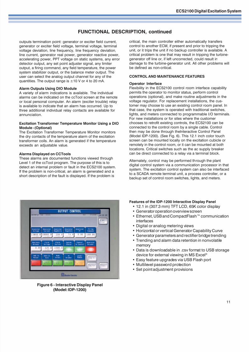
Figure 6 - Interactive Display Panel(Model: IDP-1200)
critical, the main controller either automatically transfers
control to another ECM, if present and prior to tripping theunit, or it trips the unit if no backup controller is available. A
critical problem is one that may result in tripping the turbine-
generator off line or, if left uncorrected, could result indamage to the turbine-generator unit. All other problems will
be defined as non-critical.
CONTROL AND MAINTENANCE FEATURES
Operator InterfaceFlexibility in the ECS2100 control room interface capability
permits the operator to monitor status, perform control
operations (optional), and make routine adjustments in thevoltage regulator. For replacement installations, the cus-
tomer may choose to use an existing control room panel. Inthat case, the system is operated with traditional switches,
lights, and meters connected to programmable I/O terminals.
For new installations or for sites where the customer
chooses to retrofit existing controls, the ECS2100 can beconnected to the control room by a single cable. Controlthen may be done through theInteractive Control Panel
(Model IDP-1200). (See Fig. 6). This 12.1 inch color touchscreen can be mounted locally on the excitation cubicle or
remotely in the control room, or it can be mounted at both
locations. Critical switches such as the ac supply breakercan be direct connected to a relay via a terminal block.
Alternately, control may be performed through the plantdigital control system via a communication processor in that
system. The excitation control system can also be interfaced
to a SCADA remote terminal unit, a process controller, or abackup set of control room switches, lights, and meters.
Features of the IDP-1200 Interactive Display Panel
• 12.1 in (307.3 mm) TFT LCD, 65K color display• Generator operation overview screen
• Ethernet, USB and CompactFlash™ communicationinterfaces
• Digital or analog metering views
• Horizontal or vertical Generator Capability Curve• Generator parameters and rectifier bridge trending
• Trending and alarm data retention in nonvolatile
memory• Data is downloadable in .csv format to USB storagedevice for external viewing in MS Excel®
• Easy feature upgrades via USB Flash port• Multilevel password protection• Set point adjustment provisions

7/28/2019 ECS2100_ECA3bull
http://slidepdf.com/reader/full/ecs2100eca3bull 12/12
ECS2100 Digital Excitation System
Route 143, Box 269, Highland, Illinois U.S.A. 62249Tel +1 618.654.2341 Fax +1 618.654.2351
e-mail: [email protected]
No. 59 Heshun Road Loufeng District (N),Suzhou Industrial Park, 215122, Suzhou, P.R.China
Tel +86(0)512 6346 1730 Fax +86(0)512 8227 2888
e-mail: [email protected]
b l
P.A.E. Les Pins, 67319 Wasselonne Cedex FRANCETel +33 3.88.87.1010 Fax +33 3.88.87.0808
e-mail: [email protected]
FUNCTIONAL DESCRIPTION, continued
Controller Configuration Tool (ccTool)The ccTool is an easy-to-use software tool for configuring,
monitoring, and maintaining the ECS2100 Digital ExcitationControl System purchased. It provides operators and
maintenance personnel with password access to theoperational parameters and optional configuration manage-
ment of the ECS2100 Digital Excitation System through a
laptop or desktop PC.
Level 1: View , the basic access capability, includes the
ability to monitor generator system values, digital regulatoroperating parameters such as gains, time constants, and
limiting and protective set points, and view job-specific
drawings, instruction books, help menus and help screens.
Level 2 (includes Level 1): Settings allows a user to modify
selectable and adjustable parameter settings.
Level 3 (includes Levels 1 and 2): Configuration Manage- ment includes capabilities for the reconfiguration of
software regulator function blocks and sequence controlconnections.
The ccTool can be accessed locally or from a remote
location through the RS232 port on the ECM module.
The access capability also includes the ability to view thedata collected by the ECS2100 Transient Event Recorder.
The Transient Event Recorder is a software package that
includes the standard Event and Alarm recorder that isaccessed through Level 1: View of ccTool. Special features
include the optional Single Event Recorder and Analyzer,and the optional Data Logger applications programs, both of
which are accessed through optional Level 3: Configuration
Management of ccTool. All events are time and date-tagged.
ccTool is compatible with industry standard software such as
Embedded Windows NT and Windows XP.
Transient Event Recorder
The Transient Event Recorder is a software package thatconsists of three applications programs for recording and
processing transient events.
Event and Alarm Recorder
The Event and Alarm Recorder generates a time and date
stamped list of events. The events and alarms included inthe list are pre-selected. The following items are included:
• Pickup of limiters• Operation of limiter
• Pickup of protection functions
• Operation of protection functions• Internal failure in the controllers
Up to 2000 events may be recorded, then uploaded to a
personal computer file using ccTool. An ACCESS spread-sheet may be used for viewing or printout.
Single Event Recorder and Analyzer
The Single Event Recorder records up to eight simultaneoussignals. These signals can be selected from any input or
output signals and selected internal signals. The recordshows both pre-trigger and post-trigger information. The
system provides a time that the event trigger occurred. A
selectable remote trigger or an internal one can initiate theevent recording. The Single Event Recorder can accept a
time synchronization command from an external sourcesuch as a personal computer or plant digital control system.
Each record contains up to 9600 points per channel. The
resolution is sufficient to allow a cycle-by-cycle analysis for
an event. Up to 4 records are stored. The time betweenrecorded points, as well as the number of recorded points, is
adjustable. The minimum time between recorded points isone millisecond.
These data points can be viewed using a personal computer
that can be directly connected to the ECM or connected viaa modem to the ECS2100 Digital Voltage Regulator. Using
ccTool, data for the event can be uploaded to a text file andviewed directly. The output file from the transient event is
compatible with commercially available software such asMicrosoft EXCELTM. Using such commercially availablesoftware, one can also view and plot the recorded informa-
tion without being connected to the excitation system.
Data LoggerThe Data Logger is a log of the value of selected inputs. The
items to be logged are selectable from 1 to 12 items. Thelast 1000 samples of an item that is contained in a circular
buffer are logged. The following is a list of items that, as a
minimum, may be logged:
• Generator output such as watts, vars, power factor• Excitation cubicle output, amps, and volts
• Field temperature
The time between value readings is selectable in one-second increments starting at one second. When requested,
the last 1000 values logged may be uploaded using ccTool.The log can be stored on disk or printed.


