Embed Size (px)
Citation preview
EOSENS® GE CAMERA MANUAL • HIGH SPEED CMOS CAMERA • HIGH SENSITIVITY •
EoSens GE Camera Manual Rev. 1.15Camera-Firmware: B2.02-V1.23-F1.16Camera ID: MC1364-65
Functions described in this manual may not be available with firmware versions prior than above mentioned.Information presented in this publication has been carefully checked for reliability; however, no responsibility is assumed for inaccuracies. The information contained in this document is subject to change without notice.
Copyright 2011 Mikrotron GmbH
Mikrotron GmbHLandshuter Str. 20-22D-85716 UnterschleissheimGermany
Tel.: +49 89 726342 00Fax: +49 89 726342 [email protected]
EoSens GE Camera Manual
Table of contents1 General..............................................................................................................4
1.1 For customers in the U.S.A............................................................................................................................ 41.2 For customers in Canada.............................................................................................................................. 41.3 Pour utilisateurs au Canada.......................................................................................................................... 41.4 Life Support Applications............................................................................................................................... 41.5 Declaration of conformity .............................................................................................................................. 51.6 Warranty Note............................................................................................................................................... 61.7 Remarks, Warnings....................................................................................................................................... 6
2 Introduction........................................................................................................72.1 Top level specifications.................................................................................................................................. 72.2 Electronic “Freeze Frame” Shutter................................................................................................................72.3 Differences between the camera types..........................................................................................................82.4 Using the camera.......................................................................................................................................... 8
3 Hardware............................................................................................................93.1 GigE Vision® interface.................................................................................................................................. 93.2 Power supply................................................................................................................................................. 93.3 Status LED.................................................................................................................................................... 9
4 Getting started..................................................................................................104.1 First steps.................................................................................................................................................... 10
5 Initial setup.......................................................................................................115.1 Serial number and firmware revision...........................................................................................................115.2 PowerUpProfile............................................................................................................................................ 115.3 Camera profile............................................................................................................................................. 115.4 Factory profiles............................................................................................................................................ 115.5 User profiles................................................................................................................................................ 125.6 PowerUpProfile............................................................................................................................................ 12
6 Configuration....................................................................................................136.1 GenICam® command interface................................................................................................................... 14
6.1.1 Command overview.............................................................................................................................. 146.2 Image size and position............................................................................................................................... 15
6.2.1 Setting the ROI, commands: OffsetX, OffsetY, Width and Height........................................................156.2.2 Setting multiple ROI’s, commands: MultiROICount, MultiROIOffset.....................................................156.2.3 Invert readout in x- and or y-direction, commands: ReverseX, ReverseY............................................166.2.4 DecimationXY mode (Subsampling), command: DecimationXY..........................................................16
6.3 Framerate and shutter................................................................................................................................. 176.3.1 Setting the framerate, command: AcquisitionFrameRateAbs...............................................................176.3.2 Setting the shuttertime, command: ExposureTimeRaw........................................................................176.3.3 Automatic shutter time control, command: AutoShutter........................................................................176.3.4 Setting the slopes for dynamic range adjustment, command: MultipleSlope........................................186.3.5 Non destructive readout for multi exposure, command: NonDestructiveReadout................................18
6.4 Exposure control.......................................................................................................................................... 196.4.1 Type of exposure, command: ExposureMode......................................................................................206.4.1.1 Timed................................................................................................................................................ 206.4.1.2 Trigger width...................................................................................................................................... 206.4.1.3 Trigger controlled.............................................................................................................................. 20
6.5 Image quality............................................................................................................................................... 216.5.1 Digital gain, command: DigitalGain......................................................................................................216.5.2 Blacklevel, command: BlackLevelRaw.................................................................................................216.5.3 FPN correction, command: FPNEnable................................................................................................22
6.6 Other............................................................................................................................................................ 236.6.1 In frame counter, command: InFrameCount.........................................................................................236.6.2 Test image, command: TestImageSelector..........................................................................................236.6.3 Setting threshold mode, command: GrayThreshold (optional feature).................................................24
EoSens GE Camera Manual
6.6.4 Setting binarization mode, command: BinaryModeEnable (optional feature).......................................246.6.5 Read firmware version, command: FirmwareVersion...........................................................................24
7 MC Control Tool...............................................................................................258 Firmware..........................................................................................................26
8.1 Microcontroller firmware.............................................................................................................................. 268.2 FPGA firmware............................................................................................................................................ 268.3 Firmware update procedure......................................................................................................................... 27
9 Technical Data.................................................................................................289.1 Overview...................................................................................................................................................... 289.2 Sensor defect specifications........................................................................................................................ 299.3 Spectral response........................................................................................................................................ 309.4 Bayer pattern filter....................................................................................................................................... 319.5 Connector pinning........................................................................................................................................ 32
9.5.1 Gigabit Ethernet Connector.................................................................................................................. 329.5.2 Circular power connector, 12-pin..........................................................................................................32
9.6 Timing diagrams.......................................................................................................................................... 339.6.1 Timed (Free run with electronic shutter)...............................................................................................339.6.2 Trigger width (Pulsewidth mode)..........................................................................................................339.6.3 Trigger Controlled (External sync with internal timer)...........................................................................33
9.7 Mechanical dimensions............................................................................................................................... 3410 Quick start guide for GigE Vision®.................................................................35
10.1 Software installation.................................................................................................................................. 3510.2 Install the EBus Driver.............................................................................................................................. 3510.3 Configure the network card....................................................................................................................... 3610.4 Connecting using the GEV Player............................................................................................................3710.5 Camera configuration............................................................................................................................... 38

General EoSens GE Camera Manual
1 General
1.1 For customers in the U.S.A.
This equipment has been tested and found to comply with the limits for a Class A digital device, pursuant to Part 15 of the FCC Rules. These limits are designed to provide reasonable protection against harmful interference when the equipment is operated in a commercial envir-onment. This equipment generates, uses, and can radiate radio frequency energy and, if not installed and used in accordance with the instruction manual, may cause harmful interference to radio communications. Operation of this equipment in a residential area is likely to cause harmful interference in which case the user will be required to correct the interference at his own expense. You are cautioned that any changes or modifications not expressly approved in this manual could void your authority to operate this equipment. The shielded interface cable recommended in this manual must be used with this equipment in order to comply with the lim-its for a computing device pursuant to Subpart J of Part 15 of FCC Rules.
1.2 For customers in Canada
This apparatus complies with the Class A limits for radio noise emissions set out in Radio In-terference Regulations.
1.3 Pour utilisateurs au Canada
Cet appareil est conforme aux normes Classe A pour bruits radioélectriques, spécifiées dans le Règlement sur le brouillage radioélectrique.
1.4 Life Support Applications
These products are not designed for use in life support appliances, devices, or systems where malfunction of these products can reasonably be expected to result in personal injury. Mik-rotron customers using or selling these products for use in such applications do so at their own risk and agree to fully indemnify Mikrotron for any damages resulting from such improper use or sale.
General EoSens GE Camera Manual
1.5 Declaration of conformity
Manufacturer: Mikrotron GmbH
Address: Landshuter Str. 20-2285716 UnterschleissheimGermany
Product: Camera MC1364, MC1365
The dedicated products conform to the requirements of the Council Directives 2004/108/EG for the approximation of the laws of the Member States relating to electromagnetic consist-ency. The following standards were consulted for the conformity testing with regard to electro-magnetic consistency.
EC regulation Description
EN 61000-6-3 Electromagnetic compatibility EN 61000-6-1 Immunity
Unterschleissheim, October 04, 2007
Mikrotron GmbH
Dipl.-Ing. Bernhard MindermannPresident of Mikrotron
General EoSens GE Camera Manual
1.6 Warranty Note
Do not open the body of the camera. The warranty becomes void if the body is opened.
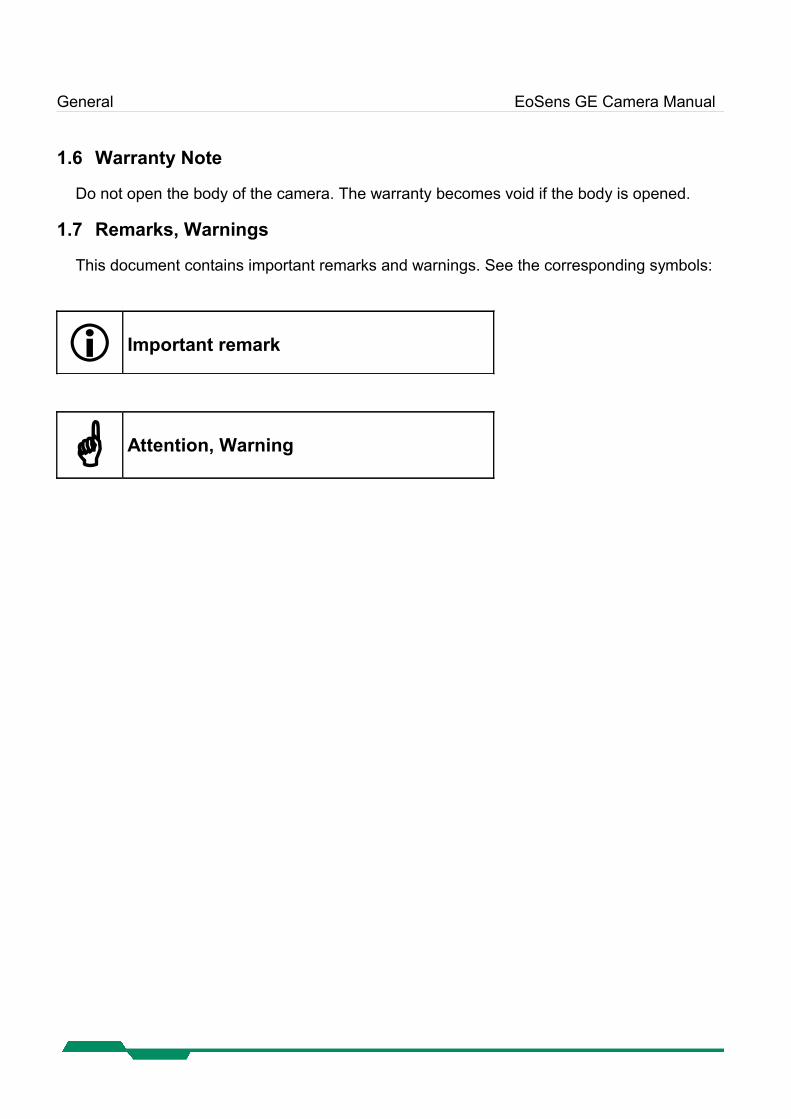
1.7 Remarks, Warnings
This document contains important remarks and warnings. See the corresponding symbols:
Important remark
Attention, Warning
Introduction EoSens GE Camera Manual
2 IntroductionThe CMOS high speed camera EoSens is a high resolution camera with 1280x1024 pixel. Be-nefits of CMOS technology are high speed, random access to pixels with free programmability and low power.
The camera uses industry-standard C-Mount or F-Mount lenses. The sensor diagonal is 22.9 mm with square pixels measuring 14 µm.
Free programmability means that the user is free to define the region of interest by size and position and the speed of data output. The frame rate can be selected between 1 fps and sev-eral thousand fps depending on resolution and video data width.
With a resolution of 1280 x 1024 pixel, 80 fps can be output via the “GigE Vision®” Interface.
2.1 Top level specifications
High resolution: 1280x1024 pixel CMOS sensor up to 1024 gray levels (10bit resolution) up to 80 full frames/s arbitrary region of interest very high sensitivity 14 µm square pixels electronic “Freeze Frame” shutter low blooming programmable via GigE Vision® interface asynchronous trigger small, compact housing wide power supply range
2.2 Electronic “Freeze Frame” Shutter
Preceding exposure, the contents of all light sensitive elements is cleared. When exposure ter-minates, accumulated charge is transferred to an analog memory associated which each pixel. It stays there until it is read out (and discharged) by the A/D conversion cycle.
As all light sensitive elements are exposed at the same time, even fast moving objects are captured without geometric distortion.
Introduction EoSens GE Camera Manual
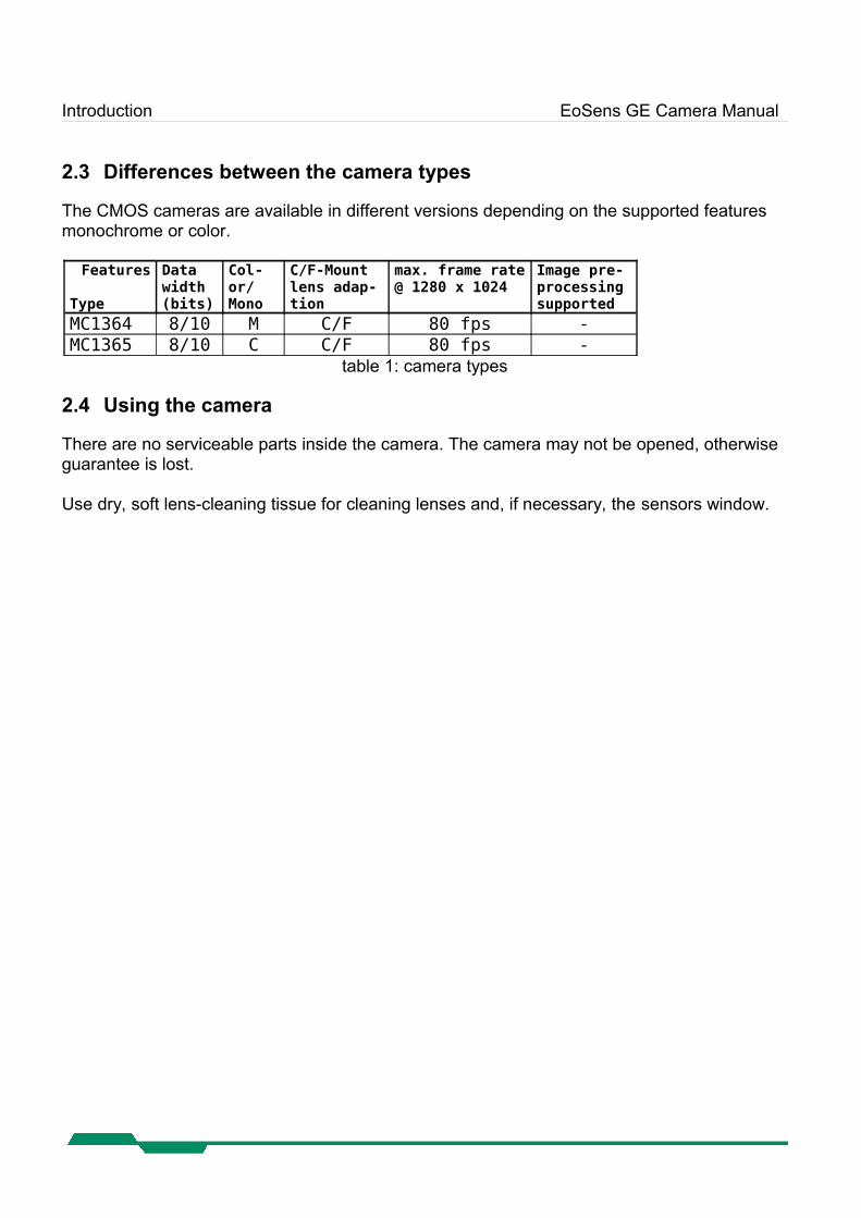
2.3 Differences between the camera types
The CMOS cameras are available in different versions depending on the supported features monochrome or color.
Features
Type
Data width(bits)
Col-or/Mono
C/F-Mount lens adap-tion
max. frame rate @ 1280 x 1024
Image pre-processing supported
MC1364 8/10 M C/F 80 fps -MC1365 8/10 C C/F 80 fps -
table 1: camera types
2.4 Using the camera
There are no serviceable parts inside the camera. The camera may not be opened, otherwise guarantee is lost.
Use dry, soft lens-cleaning tissue for cleaning lenses and, if necessary, the sensors window.
Hardware EoSens GE Camera Manual
3 Hardware
3.1 GigE Vision® interface
GigE Vision® is designed for digital cameras in machine vision applications. This interface can transfer data at a rate of 110 Mbytes/sec.
The GigE Vision® chipset and software is designed and implemented by Pleora Tech. Inc. the leading supplier of GigE Vision technology. Please refer to the PT1000 documentation for fur-ther information.
3.2 Power supply
The camera needs a DC supply voltage between 8 … 24V at a power consumption of 6 Watt max.
See also Connector pinning.
Before applying power to the camera we strongly recommend to verify the used pins of the power connector, the polarity (+/-) of the leads and the supply voltage.
The camera may only be used with a supply voltage according to the camera spe-cification. Connecting a lower or higher supply voltage, AC voltage, reversal polar-ity or using wrong pins of the power connector may damage the camera. If doing so, the warranty will expire immediately.
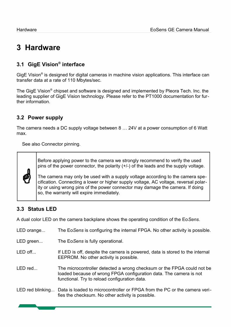
3.3 Status LED
A dual color LED on the camera backplane shows the operating condition of the EoSens.
LED orange... The EoSens is configuring the internal FPGA. No other activity is possible.
LED green... The EoSens is fully operational.
LED off... If LED is off, despite the camera is powered, data is stored to the internal EEPROM. No other activity is possible.
LED red... The microcontroller detected a wrong checksum or the FPGA could not be loaded because of wrong FPGA configuration data. The camera is not functional. Try to reload configuration data.
LED red blinking... Data is loaded to microcontroller or FPGA from the PC or the camera veri -fies the checksum. No other activity is possible.
Getting started EoSens GE Camera Manual
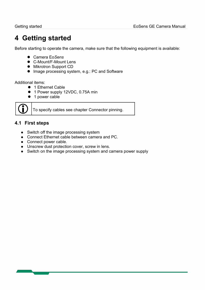
4 Getting startedBefore starting to operate the camera, make sure that the following equipment is available:
Camera EoSens C-Mount/F-Mount Lens Mikrotron Support CD Image processing system, e.g.: PC and Software
Additional items: 1 Ethernet Cable 1 Power supply 12VDC, 0.75A min 1 power cable
To specify cables see chapter Connector pinning.
4.1 First steps
Switch off the image processing system Connect Ethernet cable between camera and PC. Connect power cable. Unscrew dust protection cover, screw in lens. Switch on the image processing system and camera power supply
Initial setup EoSens GE Camera Manual
5 Initial setupThe EoSens is delivered with initial parameters and therefore does not need to be configured via the serial link.
5.1 Serial number and firmware revision
Serial number and firmware revision is provided in EoSens non volatile memory and can be read via software. The serial number is also marked on the type plate of the camera.
5.2 PowerUpProfile
The PowerUpProfile is the content of all camera registers to be loaded from non-volatile memory after power up.
5.3 Camera profile
The actual set of parameters is called Camera Profile. All changes of parameters by the serial link is reflected in the Camera Profile. On command the Camera Profile is saved to 4 user pro-files or the PowerUpProfile. It is loaded from the PowerUpProfile, 4 user profiles or 4 factory profiles. The camera profile is volatile and must be stored to the PowerUpProfile to be reactiv-ated on next power up.
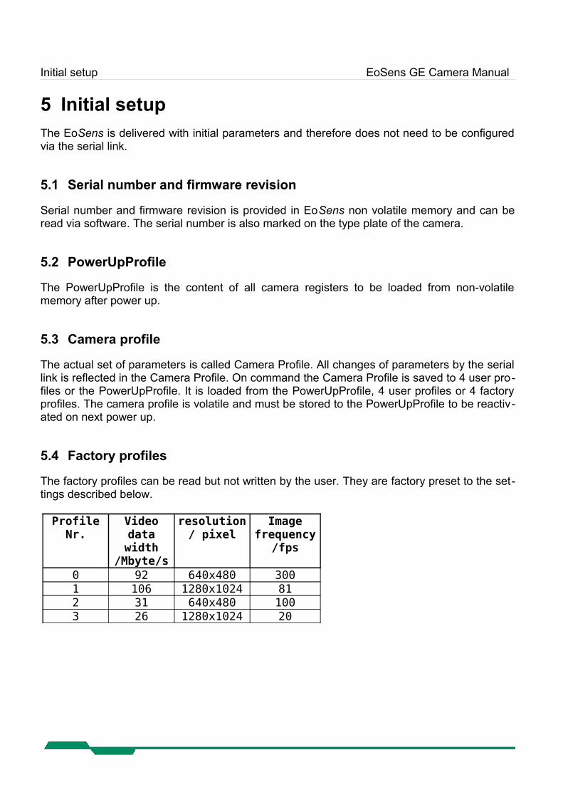
5.4 Factory profiles
The factory profiles can be read but not written by the user. They are factory preset to the set-tings described below.
Profile Nr.
Video data width
/Mbyte/s
resolution/ pixel
Imagefrequency
/fps
0 92 640x480 3001 106 1280x1024 812 31 640x480 1003 26 1280x1024 20
Initial setup EoSens GE Camera Manual
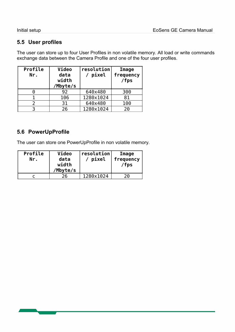
5.5 User profiles
The user can store up to four User Profiles in non volatile memory. All load or write commands exchange data between the Camera Profile and one of the four user profiles.
ProfileNr.
Video data width
/Mbyte/s
resolution/ pixel
Imagefrequency
/fps
0 92 640x480 3001 106 1280x1024 812 31 640x480 1003 26 1280x1024 20
5.6 PowerUpProfile
The user can store one PowerUpProfile in non volatile memory.
Profile Nr.
Video data width
/Mbyte/s
resolution/ pixel
Imagefrequency
/fps
c 26 1280x1024 20
Configuration EoSens GE Camera Manual
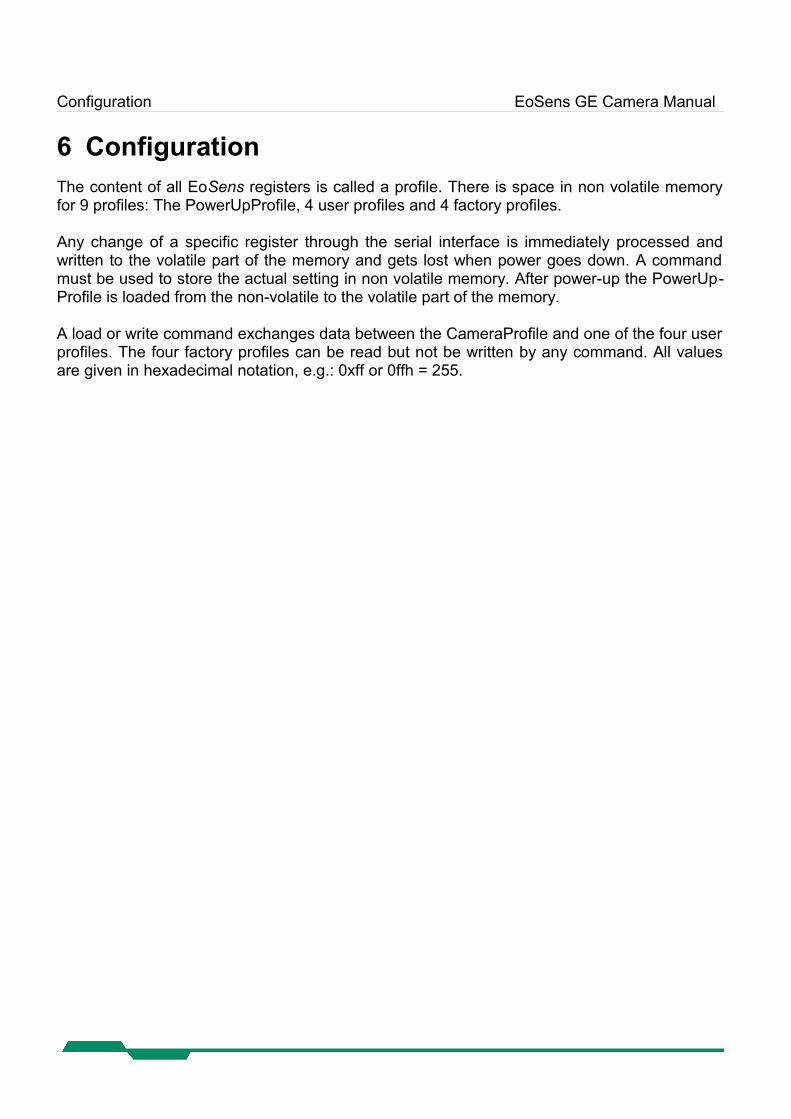
6 ConfigurationThe content of all EoSens registers is called a profile. There is space in non volatile memory for 9 profiles: The PowerUpProfile, 4 user profiles and 4 factory profiles.
Any change of a specific register through the serial interface is immediately processed and written to the volatile part of the memory and gets lost when power goes down. A command must be used to store the actual setting in non volatile memory. After power-up the PowerUp-Profile is loaded from the non-volatile to the volatile part of the memory.
A load or write command exchanges data between the CameraProfile and one of the four user profiles. The four factory profiles can be read but not be written by any command. All values are given in hexadecimal notation, e.g.: 0xff or 0ffh = 255.
Configuration EoSens GE Camera Manual
6.1 GenICam® command interface
GenICam® commands are used to change camera parameters.
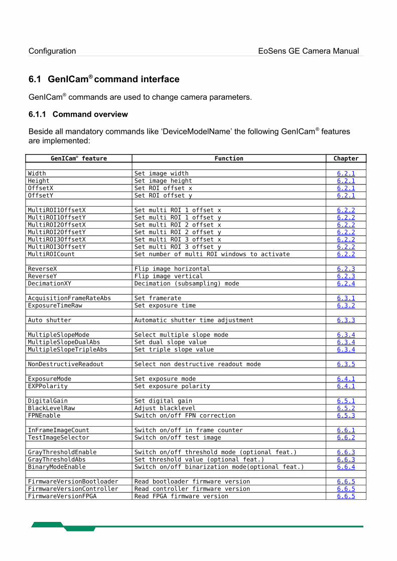
6.1.1 Command overview
Beside all mandatory commands like ‘DeviceModelName’ the following GenICam® features are implemented:
GenICam® feature Function Chapter
Width Set image width 6.2.1Height Set image height 6.2.1OffsetX Set ROI offset x 6.2.1OffsetY Set ROI offset y 6.2.1
MultiROI1OffsetX Set multi ROI 1 offset x 6.2.2MultiROI1OffsetY Set multi ROI 1 offset y 6.2.2MultiROI2OffsetX Set multi ROI 2 offset x 6.2.2MultiROI2OffsetY Set multi ROI 2 offset y 6.2.2MultiROI3OffsetX Set multi ROI 3 offset x 6.2.2MultiROI3OffsetY Set multi ROI 3 offset y 6.2.2MultiROICount Set number of multi ROI windows to activate 6.2.2
ReverseX Flip image horizontal 6.2.3ReverseY Flip image vertical 6.2.3DecimationXY Decimation (subsampling) mode 6.2.4
AcquisitionFrameRateAbs Set framerate 6.3.1ExposureTimeRaw Set exposure time 6.3.2
Auto shutter Automatic shutter time adjustment 6.3.3
MultipleSlopeMode Select multiple slope mode 6.3. 4 MultipleSlopeDualAbs Set dual slope value 6.3. 4 MultipleSlopeTripleAbs Set triple slope value 6.3. 4
NonDestructiveReadout Select non destructive readout mode 6.3. 5
ExposureMode Set exposure mode 6.4.1EXPPolarity Set exposure polarity 6.4.1
DigitalGain Set digital gain 6.5.1BlackLevelRaw Adjust blacklevel 6.5.2FPNEnable Switch on/off FPN correction 6.5.3
InFrameImageCount Switch on/off in frame counter 6.6.1TestImageSelector Switch on/off test image 6.6.2
GrayThresholdEnable Switch on/off threshold mode (optional feat.) 6.6.3GrayThresholdAbs Set threshold value (optional feat.) 6.6.3BinaryModeEnable Switch on/off binarization mode(optional feat.) 6.6.4
FirmwareVersionBootloader Read bootloader firmware version 6.6. 5 FirmwareVersionController Read controller firmware version 6.6. 5 FirmwareVersionFPGA Read FPGA firmware version 6.6. 5
Configuration EoSens GE Camera Manual
6.2 Image size and position
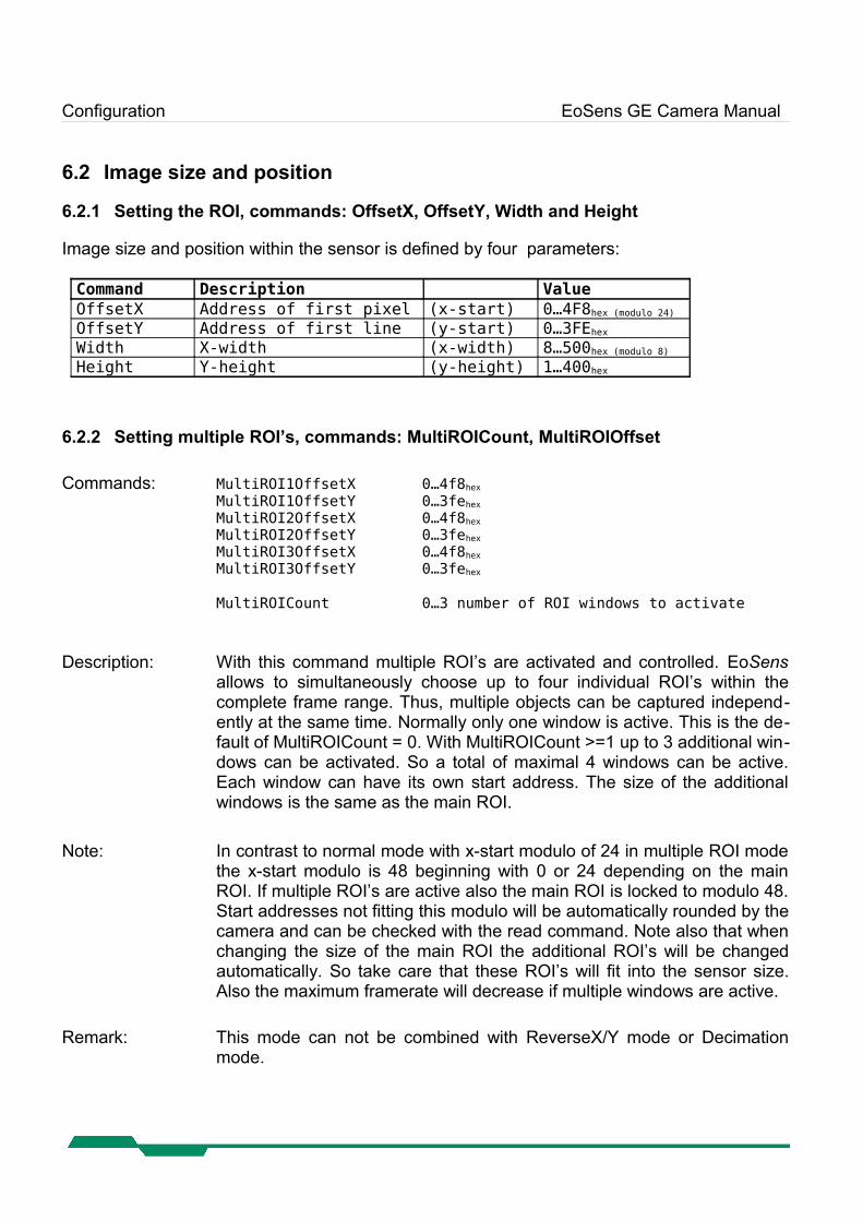
6.2.1 Setting the ROI, commands: OffsetX, OffsetY, Width and Height
Image size and position within the sensor is defined by four parameters: Command Description ValueOffsetX Address of first pixel (x-start) 0…4F8hex (modulo 24)
OffsetY Address of first line (y-start) 0…3FEhex
Width X-width (x-width) 8…500hex (modulo 8)
Height Y-height (y-height) 1…400hex
6.2.2 Setting multiple ROI’s, commands: MultiROICount, MultiROIOffset
Commands: MultiROI1OffsetX 0…4f8hex
MultiROI1OffsetY 0…3fehex
MultiROI2OffsetX 0…4f8hex
MultiROI2OffsetY 0…3fehex
MultiROI3OffsetX 0…4f8hex
MultiROI3OffsetY 0…3fehex
MultiROICount 0…3 number of ROI windows to activate
Description: With this command multiple ROI’s are activated and controlled. EoSens allows to simultaneously choose up to four individual ROI’s within the complete frame range. Thus, multiple objects can be captured independ-ently at the same time. Normally only one window is active. This is the de-fault of MultiROICount = 0. With MultiROICount >=1 up to 3 additional win-dows can be activated. So a total of maximal 4 windows can be active. Each window can have its own start address. The size of the additional windows is the same as the main ROI.
Note: In contrast to normal mode with x-start modulo of 24 in multiple ROI mode the x-start modulo is 48 beginning with 0 or 24 depending on the main ROI. If multiple ROI’s are active also the main ROI is locked to modulo 48. Start addresses not fitting this modulo will be automatically rounded by the camera and can be checked with the read command. Note also that when changing the size of the main ROI the additional ROI’s will be changed automatically. So take care that these ROI’s will fit into the sensor size. Also the maximum framerate will decrease if multiple windows are active.
Remark: This mode can not be combined with ReverseX/Y mode or Decimation mode.
Configuration EoSens GE Camera Manual
6.2.3 Invert readout in x- and or y-direction, commands: ReverseX, ReverseY
Commands: ReverseX, ReverseY
Description: This feature allows to flip the frame in x- and or y-direction.
Remark: This mode can not be combined with Decimation mode or MultiROI mode.
6.2.4 DecimationXY mode (Subsampling), command: DecimationXY
Command: DecimationXY off ; on
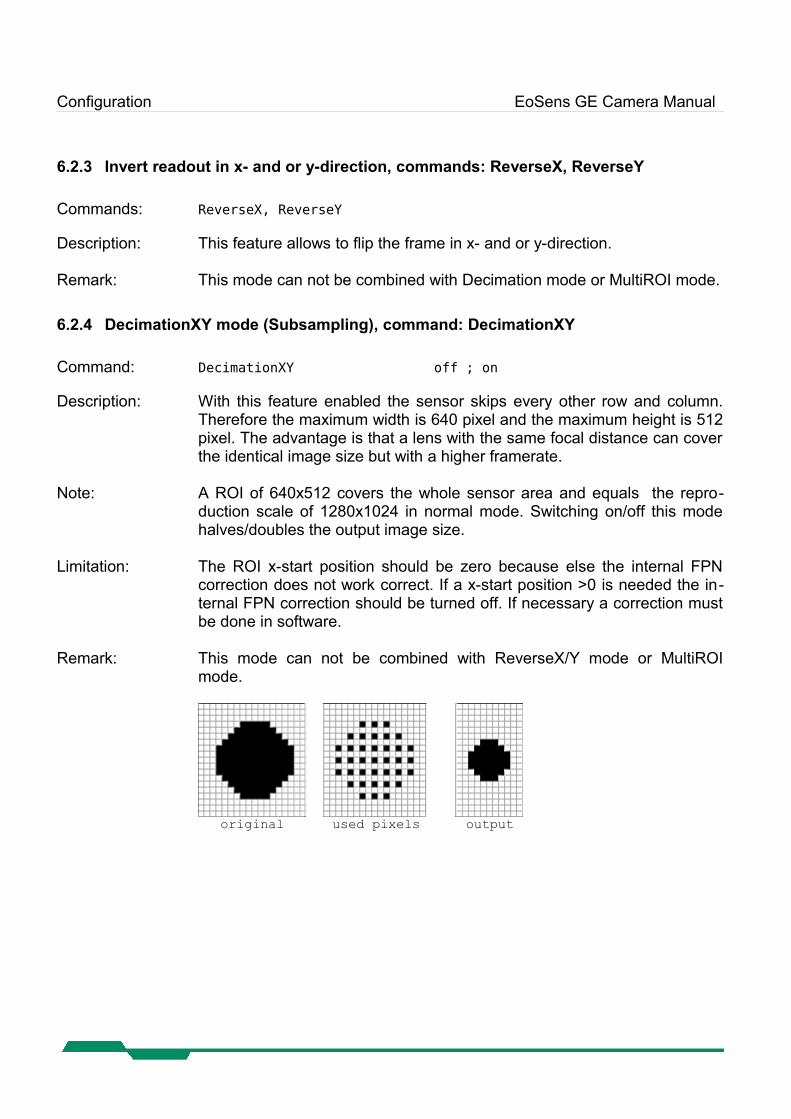
Description: With this feature enabled the sensor skips every other row and column. Therefore the maximum width is 640 pixel and the maximum height is 512 pixel. The advantage is that a lens with the same focal distance can cover the identical image size but with a higher framerate.
Note: A ROI of 640x512 covers the whole sensor area and equals the repro-duction scale of 1280x1024 in normal mode. Switching on/off this mode halves/doubles the output image size.
Limitation: The ROI x-start position should be zero because else the internal FPN correction does not work correct. If a x-start position >0 is needed the in-ternal FPN correction should be turned off. If necessary a correction must be done in software.
Remark: This mode can not be combined with ReverseX/Y mode or MultiROI mode.
original used pixels output
Configuration EoSens GE Camera Manual
6.3 Framerate and shutter
6.3.1 Setting the framerate, command: AcquisitionFrameRateAbs
Command: AcquisitionFrameRateAbsRange: <xxxxxx> = 1…3b49hex
Description: With this command the framerate (unit Hz) in free run mode can be set.
Note: The actual range depends on the current ROI.
6.3.2 Setting the shuttertime, command: ExposureTimeRaw
Command: ExposureTimeRawRange: <xxxxxx> = 2…F4240hex
Description: With this command the shuttertime (unit µS) in free run and sync with
timer mode can be set. Depending on the ROI the minimal and maximal shuttertime can vary. If maximal value for shuttertime is set, the camera will expose 1/framerate.
6.3.3 Automatic shutter time control, command: AutoShutter
Command: ASEnable <x> = 0…1 (off, on)ASBright <xx> = 00…FFhex
ASPercent <xx> = 01…64hex
ASHysteresis <xx> = 00…64hex
ASSpeed <xx> = 00…64hex
ASMin <xxxxxx> = 000000…FFFFFFhex
ASMax <xxxxxx> = 000000…FFFFFFhex
Description: This feature automatically adjusts the shuttertime depending on the object
brightness. This results in a constant image brightness. To adjust the desired image brightness the pixelvalue (brightness) <aa> for <bb> percent of the image size must be set. Additional a hysteresis can be set to prevent flickering. The adjust speed can also be set. Furthermore it's possible to limit the minimum and maximum shuttertime.
Example: For a typical scenery a brightness of 170 for 50 percent of the image is a good value. To use this setting with 20 percent hysteresis, 95 percent of the possible adjust speed and without shutter time limitation use:
ASEnable TrueASBright AAhex
ASPercent 32hex
ASHysteresis 14hex
ASSpeed 5Fhex
ASMin 000000hex
ASMax FFFFFFhex
Configuration EoSens GE Camera Manual
6.3.4 Setting the slopes for dynamic range adjustment, command: MultipleSlope
Command: MultipleSlopeRange: MultipleSlopeMode <n> = 1…3 (Number of slopes)
MultipleSlopeDualAbs <xx> = 1…63hex (percent)MultipleSlopeTripleAbs <xx> = 1…63hex (percent)
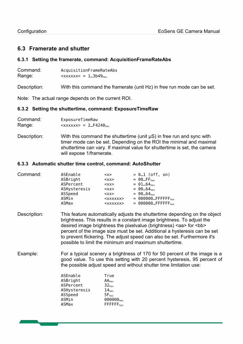
Description: This command sets the multiple slope function for dynamic range adjust-
ment. Through 2 selectable steps, the camera’s dynamic range adjust-ment option allows to approach the CMOS sensor’s linear range into a dy-namic range corresponding to the non-linear human eye. Consequently, EoSens provides definite image details even in case of extreme dark-light contrasts, which means an invaluable benefit exceptionally in image pro-cessing. With 'n'=1 the multiple slopes are deactivated and the frame will be exposed with the whole shuttertime. With activated slopes the bright pixels will be reset after <xx>percent of the shuttertime. The dual value must be smaller than triple. Depending on the mode, ROI and shuttertime the first slope can eventually not start at 1 percent. Only if valid values are set the function can be activated.
multiple slope off triple slope activated
6.3.5 Non destructive readout for multi exposure, command: NonDestructiveReadout
Command: NonDestructiveReadoutRange: <x> = 1…7 Description: This command controls the non destructive readout mode. If desired, pixel
exposure can be accumulated up to 7 times, resulting in alternative image exposures. The optimally exposed image can be selected for further pro-cessing. At indefinite lighting conditions, as in 24 hour outdoor applica-tions, EoSens becomes the high speed camera that spots everything. With x=1 after every frame the pixels are reset (normal operation). With x>1 all pixels will be read out multiple times (max. 7) after they are reset. So for low light the last samples are useful and for high light levels the first samples are useful.
Configuration EoSens GE Camera Manual
6.4 Exposure control
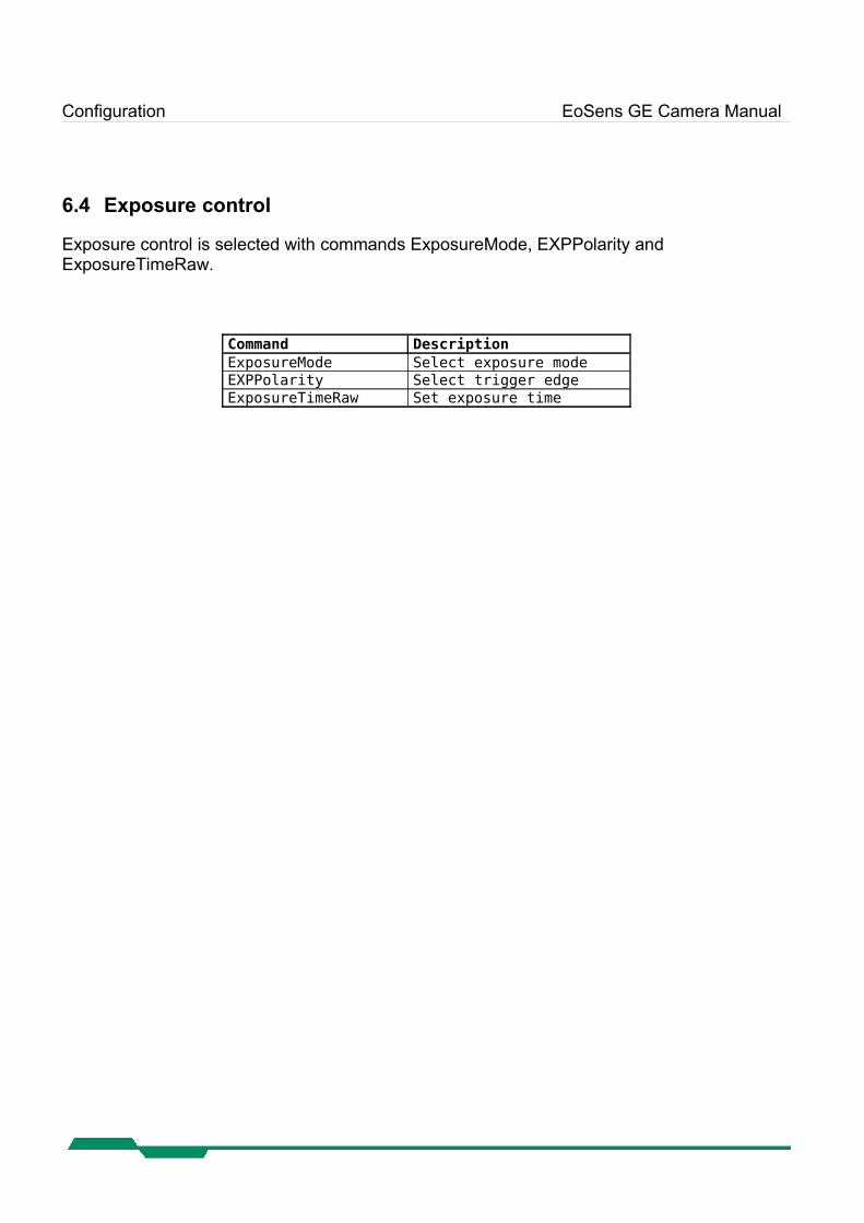
Exposure control is selected with commands ExposureMode, EXPPolarity andExposureTimeRaw.
Command DescriptionExposureMode Select exposure modeEXPPolarity Select trigger edgeExposureTimeRaw Set exposure time
Configuration EoSens GE Camera Manual
6.4.1 Type of exposure, command: ExposureMode
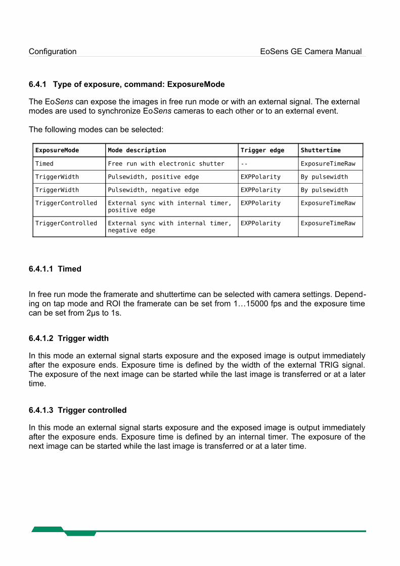
The EoSens can expose the images in free run mode or with an external signal. The external modes are used to synchronize EoSens cameras to each other or to an external event.
The following modes can be selected: ExposureMode Mode description Trigger edge Shuttertime
Timed Free run with electronic shutter -- ExposureTimeRaw
TriggerWidth Pulsewidth, positive edge EXPPolarity By pulsewidth
TriggerWidth Pulsewidth, negative edge EXPPolarity By pulsewidth
TriggerControlled External sync with internal timer,positive edge
EXPPolarity ExposureTimeRaw
TriggerControlled External sync with internal timer,negative edge
EXPPolarity ExposureTimeRaw
6.4.1.1 Timed
In free run mode the framerate and shuttertime can be selected with camera settings. Depend-ing on tap mode and ROI the framerate can be set from 1…15000 fps and the exposure time can be set from 2µs to 1s.
6.4.1.2 Trigger width
In this mode an external signal starts exposure and the exposed image is output immediately after the exposure ends. Exposure time is defined by the width of the external TRIG signal. The exposure of the next image can be started while the last image is transferred or at a later time.
6.4.1.3 Trigger controlled
In this mode an external signal starts exposure and the exposed image is output immediately after the exposure ends. Exposure time is defined by an internal timer. The exposure of the next image can be started while the last image is transferred or at a later time.
Configuration EoSens GE Camera Manual
6.5 Image quality
6.5.1 Digital gain, command: DigitalGain
Command: DigitalGainRange : <xxxx> = 0 or 0400…1000hex
Description: The digital gain can be set from 0400hex which is equivalent to gain 1x to 1000hex which is equivalent to gain 4x. Setting the gain to 0 switches off the correction completely.
6.5.2 Blacklevel, command: BlackLevelRaw
Command: BlackLevelRawRange: <xx> = 32…C8hex
Description: This command adjusts blacklevel. The value 80hex is the factory calibrated
default. Increase or decrease this value slightly to adjust blacklevel.
Configuration EoSens GE Camera Manual
6.5.3 FPN correction, command: FPNEnable
Command: FPNEnable
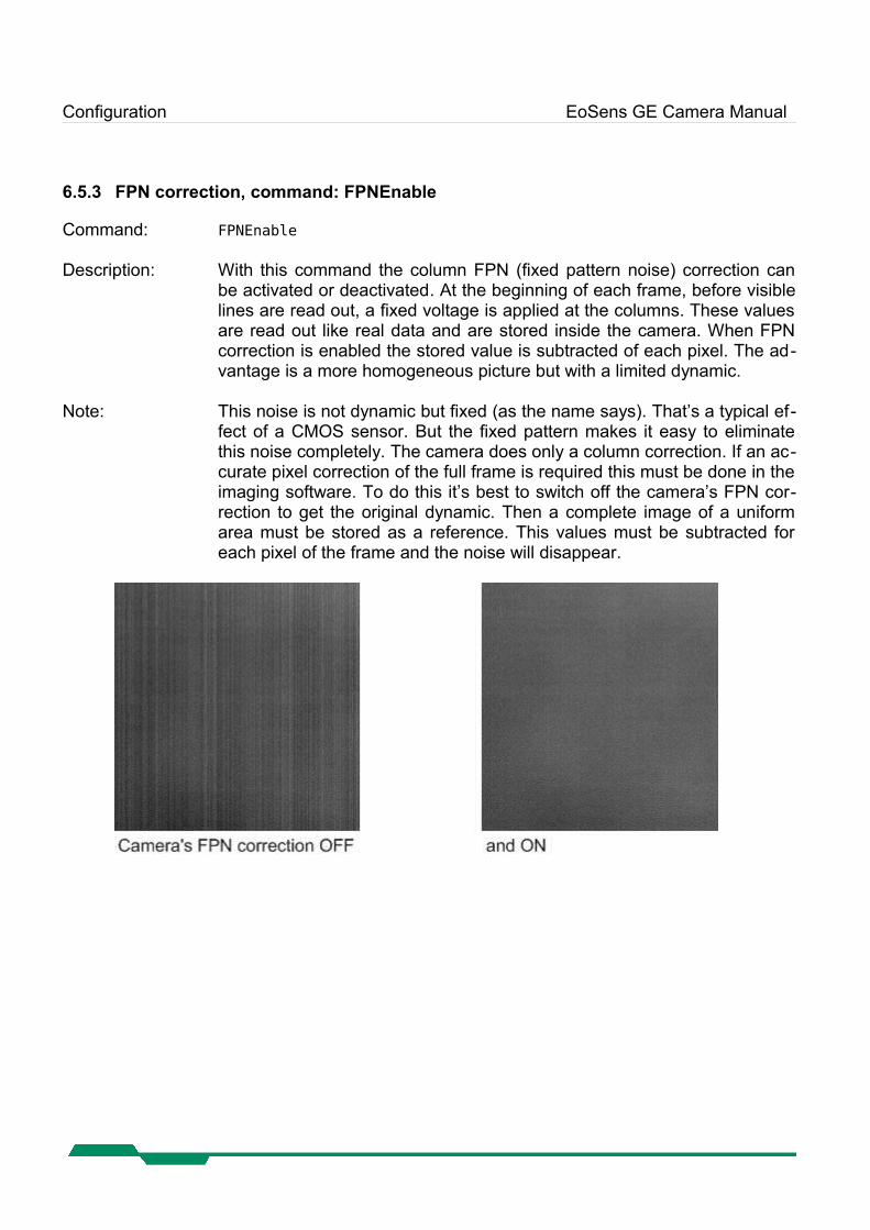
Description: With this command the column FPN (fixed pattern noise) correction can be activated or deactivated. At the beginning of each frame, before visible lines are read out, a fixed voltage is applied at the columns. These values are read out like real data and are stored inside the camera. When FPN correction is enabled the stored value is subtracted of each pixel. The ad-vantage is a more homogeneous picture but with a limited dynamic.
Note: This noise is not dynamic but fixed (as the name says). That’s a typical ef-fect of a CMOS sensor. But the fixed pattern makes it easy to eliminate this noise completely. The camera does only a column correction. If an ac-curate pixel correction of the full frame is required this must be done in the imaging software. To do this it’s best to switch off the camera’s FPN cor-rection to get the original dynamic. Then a complete image of a uniform area must be stored as a reference. This values must be subtracted for each pixel of the frame and the noise will disappear.
Configuration EoSens GE Camera Manual
6.6 Other
6.6.1 In frame counter, command: InFrameCount
Command: InFrameCount
Description: If a sequence of frames is to be recorded for long time at a high frame rate, it can be useful to mark the images for later identification or check for completeness. EoSens has a 32-Bit image counter whose count can re-place the first four pixel of every image. It is incremented by every new im-age.
6.6.2 Test image, command: TestImageSelector
Command: TestImageSelector
Description: For testing of camera logic and video data transmission, sensor data can be replaced by an internal gray scale pattern with pixel values of 0..255.
Configuration EoSens GE Camera Manual
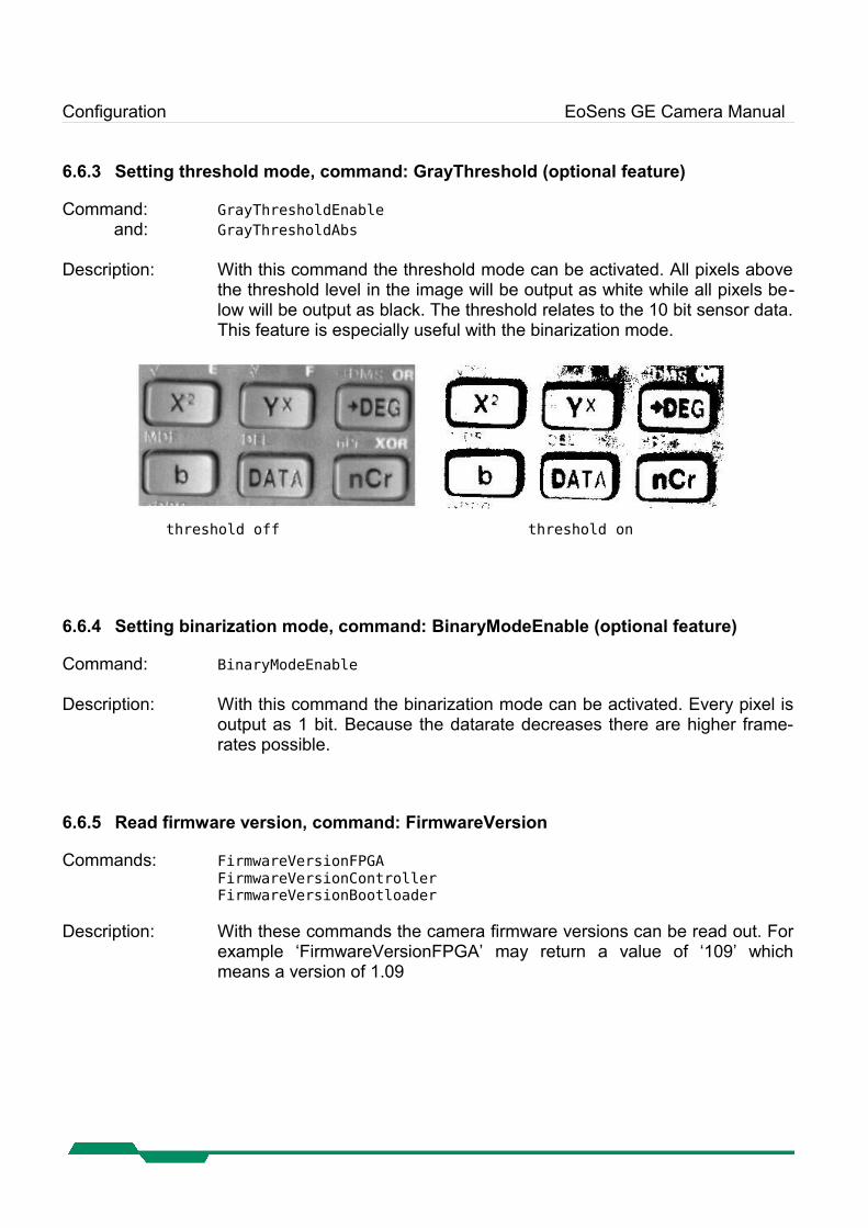
6.6.3 Setting threshold mode, command: GrayThreshold (optional feature)
Command: GrayThresholdEnableand: GrayThresholdAbs
Description: With this command the threshold mode can be activated. All pixels above the threshold level in the image will be output as white while all pixels be-low will be output as black. The threshold relates to the 10 bit sensor data. This feature is especially useful with the binarization mode.
threshold off threshold on
6.6.4 Setting binarization mode, command: BinaryModeEnable (optional feature)
Command: BinaryModeEnable
Description: With this command the binarization mode can be activated. Every pixel is output as 1 bit. Because the datarate decreases there are higher frame-rates possible.
6.6.5 Read firmware version, command: FirmwareVersion
Commands: FirmwareVersionFPGAFirmwareVersionControllerFirmwareVersionBootloader
Description: With these commands the camera firmware versions can be read out. For example ‘FirmwareVersionFPGA’ may return a value of ‘109’ which means a version of 1.09
MC Control Tool EoSens GE Camera Manual
7 MC Control ToolThe MC Control Tool must be installed on a Windows PC. (Win9x, WinNT, Win2K, WinXP) by means of the setup software. See also www.mikrotron.de to download the latest version.
This software provides an almost self explaining user interface to modify any camera paramet-er. The description of the parameters follows the marked chapters in this user manual.
To use this tool with the EoSens camera the serial interface is integrated in the GigE interface. You do not need any other additional cable.
Firmware EoSens GE Camera Manual
8 FirmwareThe camera possesses programmable devices, which are working with some firmware pack-ages. New cameras were programmed with all needed firmware packages and will not need any update.
For customized firmware or additional features the camera offers the possibility to update some of the firmware versions. The procedure of updating depends on the firmware package.
Do not update more than 1 firmware at the same time. In case of updating more than 1 firmware, please start with application pro-gram, then FPGA program follows.
8.1 Microcontroller firmware
The microcontroller works with 2 programs, the bootloader and the application program.
The bootloader is the basic program of the microcontroller, which ensures some basic func-tions (e.g. communication, loading application program) and cannot be changed or updated. In standard use of the camera it will never work in the bootloader program. It’s only used for updating the application program.
The application program is the active microcontroller program in the camera, which supports communication, data handling and FPGA program updates.
See description of update procedure in chapter “Firmware update procedure”.
8.2 FPGA firmware
EoSens’s logic is integrated into a FPGA (Field Programmable Gate Array), which’s configura-tion is stored in an EEPROM. Upon power up or a command the FPGA is loaded with this con-figuration. Configuration data can be downloaded via the serial interface. Mikrotron may provide configuration files (*.ibf) on request. After download of configuration data, this data is permanently stored in EEPROM and the FPGA is configured with the new data. Besides a power cycle or the :c command can be used to reconfigure the FPGA with the internally stored configuration data.
See description of update procedure in chapter “Firmware update procedure”.
Firmware EoSens GE Camera Manual
8.3 Firmware update procedure
Before you disable the loaded firmware please ensure that you have an adequate application firmware version to load (e.g. EoSens….A101.ibf for application firmware, EoSens…F101.ibf for FPGA firmware).
After this command the camera may not be able to deliver any images, load/send/store register or profile data. The status led of the camera will turn to red.YOU CAN NOT UNDO THIS COMMAND.
Start MC Control Tool and select “EoSens” camera. Wait until the info screen displays serial no. and firmware.
Select in menu “Tools” “Update microcontroller firmware” or “Update FPGA firmware”
Choose file (e.g. MC1364M626A101.ibf for microcontroller or MC136xM651F101.ibf for FPGA) and open it. The file transfer will start immediately. While loading the LED will blink red
Download of *.ibf file via serial link takes app. 1 - 5 min depending on the used baudrate. There should be no loss of power or communication during this time!
Wait until file transfer has finished and the status led stays on. If the upload of the file was successful, the led will turn to green, otherwise it will be red.
Verify version in “EoSens” info screen. The new firmware version will be displayed. If the version is identical to the expected the camera is ready to use for capturing images.
Technical Data EoSens GE Camera Manual
9 Technical Data
9.1 Overview
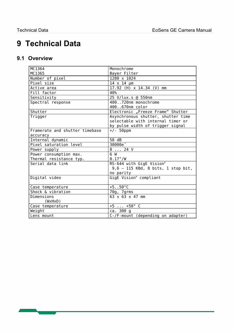
MC1364MC1365
MonochromeBayer Filter
Number of pixel 1280 x 1024Pixel size 14 x 14 µmActive area 17.92 (H) x 14.34 (V) mmFill factor 40%Sensitivity 25 V/lux.s @ 550nmSpectral response 400..720nm monochrome
400..670nm colorShutter Electronic „Freeze Frame“ ShutterTrigger Asynchronous shutter, shutter time
selectable with internal timer or by pulse width of trigger signal
Framerate and shutter timebase accuracy
+/- 50ppm
Internal dynamic 58 dBPixel saturation level 30000e¯Power supply 8 ... 24 V Power consumption max.Thermal resistance typ.
6 W0.17°/W
Serial data link RS-644 with GigE Vision®
9,6 – 115 KBd, 8 bits, 1 stop bit, no parity
Digital video GigE Vision® compliant
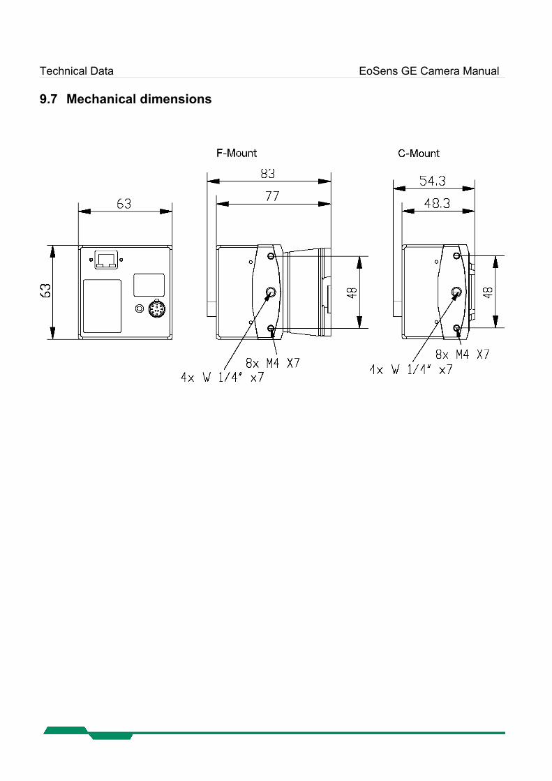
Case temperature +5..50°CShock & vibration 70g, 7grmsDimensions (WxHxD)
63 x 63 x 47 mm
Case temperature +5 ... +50° CWeight ca. 300 gLens mount C-/F-mount (depending on adapter)
Technical Data EoSens GE Camera Manual
9.2 Sensor defect specifications
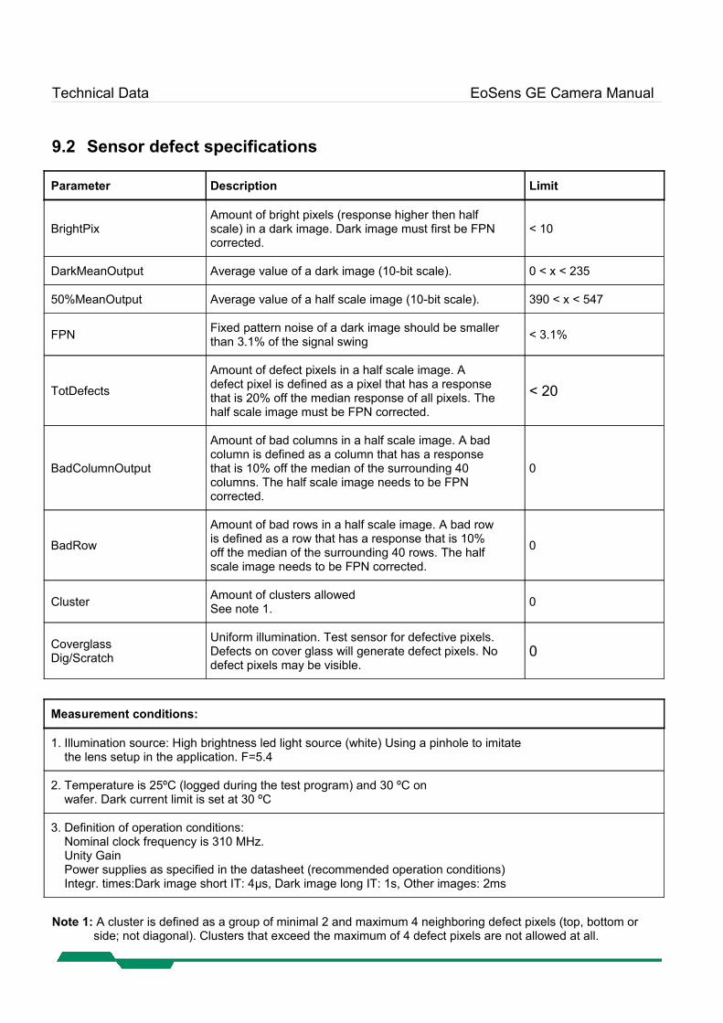
Parameter Description Limit
BrightPixAmount of bright pixels (response higher then halfscale) in a dark image. Dark image must first be FPNcorrected.
< 10
DarkMeanOutput Average value of a dark image (10-bit scale). 0 < x < 235
50%MeanOutput Average value of a half scale image (10-bit scale). 390 < x < 547
FPN Fixed pattern noise of a dark image should be smallerthan 3.1% of the signal swing < 3.1%
TotDefects
Amount of defect pixels in a half scale image. Adefect pixel is defined as a pixel that has a responsethat is 20% off the median response of all pixels. Thehalf scale image must be FPN corrected.
< 20
BadColumnOutput
Amount of bad columns in a half scale image. A badcolumn is defined as a column that has a responsethat is 10% off the median of the surrounding 40columns. The half scale image needs to be FPNcorrected.
0
BadRow
Amount of bad rows in a half scale image. A bad rowis defined as a row that has a response that is 10%off the median of the surrounding 40 rows. The halfscale image needs to be FPN corrected.
0
Cluster Amount of clusters allowedSee note 1. 0
CoverglassDig/Scratch
Uniform illumination. Test sensor for defective pixels.Defects on cover glass will generate defect pixels. Nodefect pixels may be visible.
0
Measurement conditions:
1. Illumination source: High brightness led light source (white) Using a pinhole to imitate the lens setup in the application. F=5.4
2. Temperature is 25ºC (logged during the test program) and 30 ºC on wafer. Dark current limit is set at 30 ºC
3. Definition of operation conditions: Nominal clock frequency is 310 MHz. Unity Gain Power supplies as specified in the datasheet (recommended operation conditions) Integr. times:Dark image short IT: 4μs, Dark image long IT: 1s, Other images: 2ms
Note 1: A cluster is defined as a group of minimal 2 and maximum 4 neighboring defect pixels (top, bottom or side; not diagonal). Clusters that exceed the maximum of 4 defect pixels are not allowed at all.
Technical Data EoSens GE Camera Manual
9.3 Spectral response
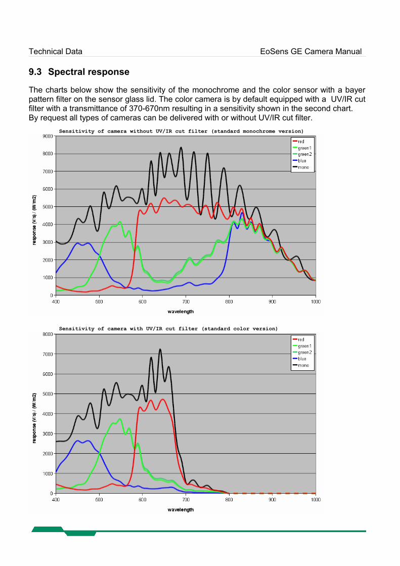
The charts below show the sensitivity of the monochrome and the color sensor with a bayer pattern filter on the sensor glass lid. The color camera is by default equipped with a UV/IR cut filter with a transmittance of 370-670nm resulting in a sensitivity shown in the second chart.By request all types of cameras can be delivered with or without UV/IR cut filter.
Sensitivity of camera without UV/IR cut filter (standard monochrome version)
Sensitivity of camera with UV/IR cut filter (standard color version)
Technical Data EoSens GE Camera Manual
9.4 Bayer pattern filter
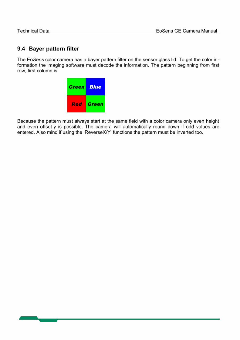
The EoSens color camera has a bayer pattern filter on the sensor glass lid. To get the color in -formation the imaging software must decode the information. The pattern beginning from first row, first column is:
Green Blue
Red Green
Because the pattern must always start at the same field with a color camera only even height and even offset-y is possible. The camera will automatically round down if odd values are entered. Also mind if using the ‘ReverseX/Y’ functions the pattern must be inverted too.
Technical Data EoSens GE Camera Manual
9.5 Connector pinning
9.5.1 Gigabit Ethernet Connector
Connector type: RJ45 female
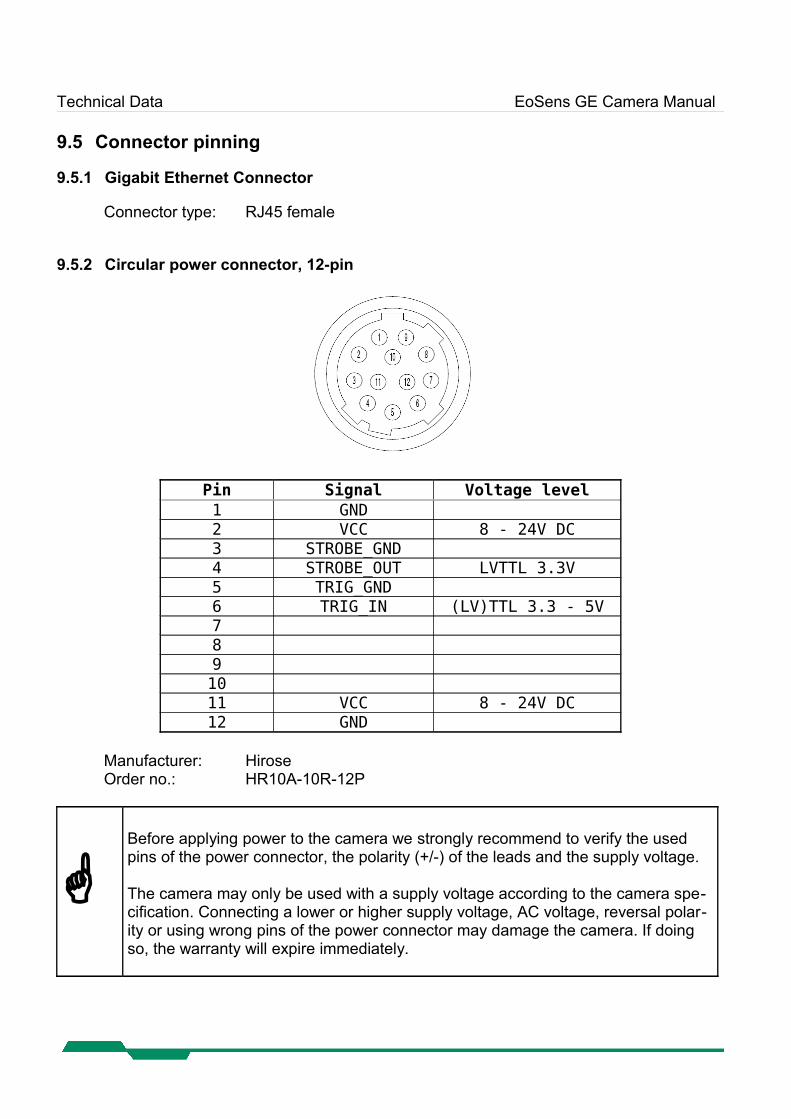
9.5.2 Circular power connector, 12-pin
Pin Signal Voltage level1 GND2 VCC 8 - 24V DC3 STROBE_GND4 STROBE_OUT LVTTL 3.3V5 TRIG_GND6 TRIG_IN (LV)TTL 3.3 - 5V7 8 9 10 11 VCC 8 - 24V DC12 GND
Manufacturer: HiroseOrder no.: HR10A-10R-12P
Before applying power to the camera we strongly recommend to verify the used pins of the power connector, the polarity (+/-) of the leads and the supply voltage.
The camera may only be used with a supply voltage according to the camera spe-cification. Connecting a lower or higher supply voltage, AC voltage, reversal polar-ity or using wrong pins of the power connector may damage the camera. If doing so, the warranty will expire immediately.
Technical Data EoSens GE Camera Manual
9.6 Timing diagrams
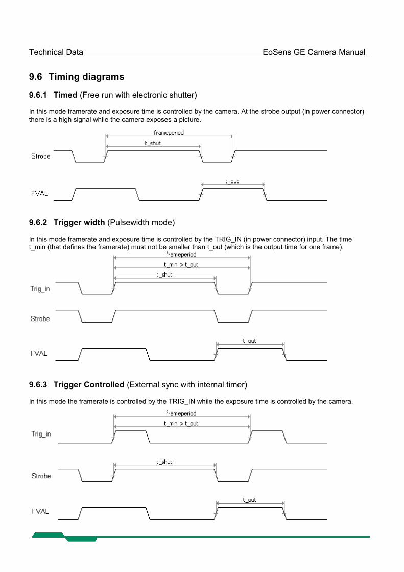
9.6.1 Timed (Free run with electronic shutter)
In this mode framerate and exposure time is controlled by the camera. At the strobe output (in power connector) there is a high signal while the camera exposes a picture.
9.6.2 Trigger width (Pulsewidth mode)
In this mode framerate and exposure time is controlled by the TRIG_IN (in power connector) input. The time t_min (that defines the framerate) must not be smaller than t_out (which is the output time for one frame).
9.6.3 Trigger Controlled (External sync with internal timer)
In this mode the framerate is controlled by the TRIG_IN while the exposure time is controlled by the camera.
Technical Data EoSens GE Camera Manual
9.7 Mechanical dimensions
Quick start guide for GigE Vision® EoSens GE Camera Manual
10 Quick start guide for GigE Vision®
This guide describes the basic steps to set up a connection to a GigE Vision camera using the EBus driver. Other driver configurations are possible but for high performance it is recommen-ded to use the EBus Optimal Driver if possible.
10.1 Software installation
This guide requires to install the eBUS-PureGEV Package.After installation documentation and programming samples can be found in<Program files>\Pleora Technologies Inc\eBUS-PureGEV Package\
Note: Since your camera is a GigE Vision device it's recommended to use the PureGEV SDK for writing camera applications. Alternatively the IPort SDK (eBUS-Vision Package) can be used.
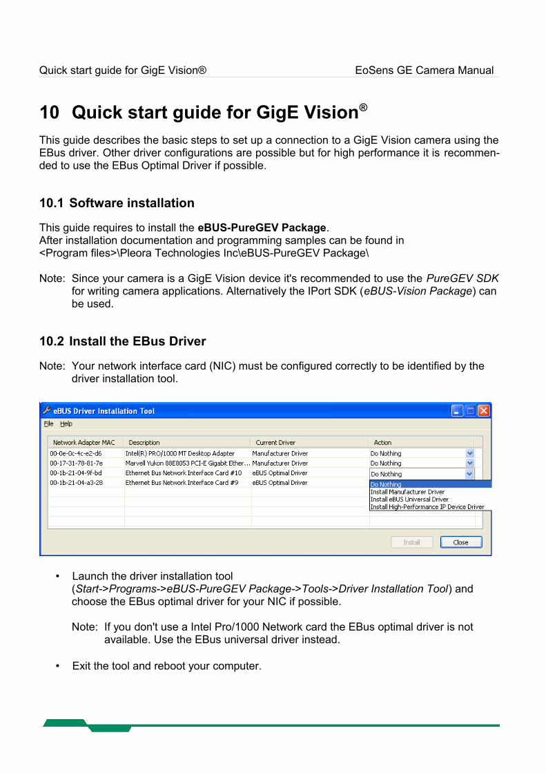
10.2 Install the EBus Driver
Note: Your network interface card (NIC) must be configured correctly to be identified by the driver installation tool.
• Launch the driver installation tool(Start->Programs->eBUS-PureGEV Package->Tools->Driver Installation Tool) and choose the EBus optimal driver for your NIC if possible.
Note: If you don't use a Intel Pro/1000 Network card the EBus optimal driver is not available. Use the EBus universal driver instead.
• Exit the tool and reboot your computer.
Quick start guide for GigE Vision® EoSens GE Camera Manual
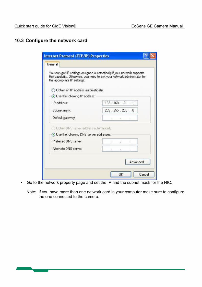
10.3 Configure the network card
• Go to the network property page and set the IP and the subnet mask for the NIC.
Note: If you have more than one network card in your computer make sure to configure the one connected to the camera.
Quick start guide for GigE Vision® EoSens GE Camera Manual
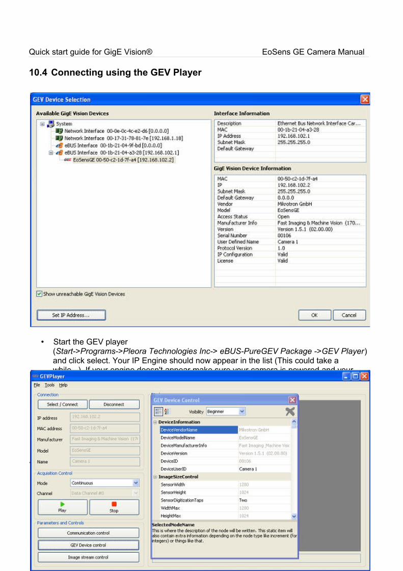
10.4 Connecting using the GEV Player
• Start the GEV player(Start->Programs->Pleora Technologies Inc-> eBUS-PureGEV Package ->GEV Player) and click select. Your IP Engine should now appear in the list (This could take a while ..). If your engine doesn't appear make sure your camera is powered and your network connection is configured.
Note: The GEV Player can only be used with Ebus Drivers (Optimal or Universal).
• Select the IP Engine from the list and set the IP and subnet mask (right click) to get a connection to the network card.
Note: Show unreachable GigE Vision Devices must be selected to find your camera:
10.5 Camera configuration
• Click GEV Device control to configure the camera.