Embed Size (px)
Citation preview

f'--~
IAD-753 364
CALCULATION OF THE THREE DIMENSIONALPARTICLE TRAJECTORIES IN A TURBINE STAGE
M. Fathy Hussein, et al
Cincinnati University
Prepared for:
Army Research Office
September 1972
DISTRIBUTED BY:
Natlonal Technica Infonuaton ServiceU. S. DEPARTMENT OF COMMERCE5285 Port' Royal Road, Springfield Va. 22151
L _11

r -- Z i 9 -_
SI~fV__ __ __ _ _ W_
-A-

Jr • cty i f tteito -
DOCWA1E:T CM4*rF~,' "ATA.- R & D A
(S.curlt)j* clnasaiicatln of l1le. bhod of hbartmetl onuS In .•,•fpo,.•. ,.,, I, o ,.qf be enturud wu.,, It$" ovefIlqf rt.?pft 1I- ClPa0lS'd. 41. OIIleNA TOPICr AC TI VI TY (Co**pornto author) 4a. tt014' S1ZCUFI9TY CLA1II5FICA.TIONTYUnclassified
University of Cincinnati ,--. .. . .NA
3. REPORT TITLE
Calculation of the Three Dimensional Particle Trajectories in aTurbine Stage
4. OESCRIPTIV IV NO T CS (It'pe of report and Ineflusive datea)
Technical Report "__"_ _
11. AU THOR(S) (FAIrs name, middle In los, t naMe)
M. Fathy Hussein and W. Tabakoff
0. REPORT DATE 7fl. OF-Aý&Q 0 S NO. IFRepro
September 1972 " toz , 7.OR. CONTRAC 1 ON GRANT 10. to. ORIGINATOR'S REPORT NU'IKO"M
DABC04-69-C-0016b €. .PROECto. Project Themis Report No. 27-33
C. 9b. OTHER Rcp~nT NOSIS)(Any o~ter number "h:tMay be .aselledthis report)
4.
10. OISTRIBUTION STATEMENT
.Distribution of this report is unlimited
It- SUPPLEMENTARY NOTES 12. SPONSORING MILITARY ACTIVITYI U.S. Army Research Office-DurhamNone Box CM, Duke StationDurham, North Carolina 27706
I8. ArSTOACT
The equations of motion, in three dimensions, of solid particlesentrained by a gas flow through the stationary and rotating cascadesof a turbine are derived. 'The gas velocity components and density atall the mesh points of a square grid constructed in the flow channelsare computed assuming a compressible flow. Formulas to determine theproper drag on the particles for a wide range of, Reynolds numbers aregiven. *A gas particle flow tunnel &s used to investigate experimentallythe phenomenon of particle impact with the turbine blades or casing andtheir rebound from these walls. Formulas for the restitution ratio dueto collision and the rebound to incidence angle ratio are derived. Thisinformation is used in the equations of motion of the solid particles. I*
The dynamic behavior of the solid particles ip the turbine stage, inamely their absolute and relative trajectories, absolute nondimensional
• velocity history in the channel, and their velocity diagra.rs as comparedi to that of the gas, is investigated.
.Key Words:
Solid Particulate Flow Turbomachinery Erosion PhenomenaParticle Trajectory
I. '' ~ V A tl /J 00 $1~*ji. 0411 11470. 1 JAIl '1. . .M1CM #A#I..; t., ., ,., oa4I.- , r - . Unclassified
+ ~ ~ scrt -•;•'1,i• c ati+,:+on . .

PROJECT THEMIS REPORT NO. 72-33
CALCULATION OF THE THREEDIMENSIONAL PARTICLE
TRAJECTORIES T"' A TURBINE STAGE
M. Fathy Hussein and W. Tabakoff
September 1972
This work was supported by the U.S. Army
Research Office - Durham under Project
Themis Contract Number DAHC04-69-C-0016
Reproduced byNATIONAL TECHNICALINFORMATION SERVICE
U S Oeparmnnf of CommerceSpringfield VA 22151
DEPARTMENT OF AEROSPACE ENGINEERINGUniversity of Cincinnati, Cincinnati, Ohio 45221
"Approved for public rE ,( i,,unlimited.

-ow
i TABLE OF CONTENTS
Page
I LIST OF ILLUSTRATIONS ............................. ii
I NOMENCLATURE .............................................. vi
ABSTRACT ........................................... ix
I INTRODUCTION ................................................ 1
FORCES ON SPHERICAL PARTICLES MOVING IN A GAS STREAM ........ 4
Drag Force ...................................... 4
Force Due to Pressure Gradient in the FlowAround the Particle ........... ................. 6
EQUATIONS OF MOTION OF SOLID PARTICLES ENTRAINEDBY THE GAS FLOW IN A ROTAI'NG CASCADE.. .................. 8
EXPERIMENTAL STUDY OF THE IMPACT AND REBOUND PHENOMENONI OF SOLID PARTICLES FROM THE WALLS ................... ... 12
GAS FLOW PROPERTIES IN A BLADE TO BLADE SURFACE OFREVOLUTION OF A ROTATING CASCADE ................. .... 14
I NUMERICAL EXAMPLE .......... ...................... .. 15
L Particles Dynamic Behavior in the Turbine Stage. .. 16
CONCLUSION ............. .......................... .. 20
[ REFERENCES ........... .......................... .. 21
I[I
i

LIST OF ILLUSTRATIONS
Fi cure Pace
1 Drag Coefficient for Spherical Particle .......... ... 23
3 . . . . . . . . . . . . . . . . . . . . . . . . . . . 25.4 ..................................................... 25
. .................... ......................... 26
6 Drop in Particle Relative Tangential VelocityDue to Collision ......... ................... .. 27
7 Drop in Particle Relative Normal VelocityDue to Collision ................................... 27
8 Nondimensional Angle of Rebound .... ............ .. 28I9 Drop in Particle Relative Velocity
Due to Collision (Restitution Ratio) ........... .. 28
10 Axsymmetric Coordinate Surface .... ............ .. 29
11 Gas Flow Control Volume ........... ........... 29
12 Turbine Stage Dimensions ....... .............. .. 30
13 Combined Gas Velocity Diagram(Turbine Stage) ............. ................. . .. 30
14 Mesh Points for Turbine Blading .... ........... ... 31
15 Axial and Tangential Componentsof Particle Trajectories ....... .............. .. 32
16 Axial and Tangential Components of ParticleTrajectories Relative to the Rotor Blades ......... ... 33
17 Axial and Radial Components of Particle Trajectories . 34
18 Particle Nondimensional Absolute Velocities .... ..... 34
19 Axial and Tangential Components ofParticle Trajectories .............................. 35
20 Axial and Tangential Components of ParticleTrajectories Relative to the Rotor Blades ......... ... 35
21 Axial and Radial Components of
Particle Trajectories .............................. 36
22 Particle Nondimensional Absolute Velocities ...... ... 36
ii

I Figure Page
23 Axial and Tangential Components ofJ Particle Trajectories. . ........... ..... 37
24 Axial and Tangential Components of ParticlejTrajectories Relative to the Rotor Blades ......... ... 37
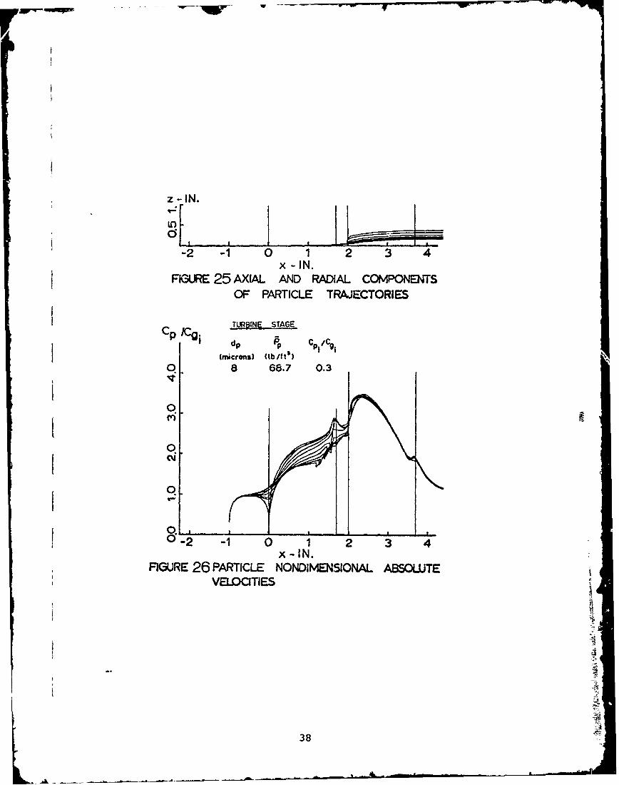
25 Axial and Radial Components of Particle
Trajectories .......... ..................... .. 38
26 Particle Nondimensional Absolute Velocities .... ...... 38
27 Axial and Tangential Components of ParticleTrajectories (Effect of d ).) .................. .... 39p
28 Axial and Tangential Components of Particle
Trajectories Relative to the Rotor Blades(Effect of d.p.) .. .... ................... 40
29 A;:ial and Radial Components of ParticleTrajectories .......... ..................... .. 41
30 Particle Nondimensional Absolute Velocities(Effect of d.p.) ....... .................... .... 41
31 Particle velocity Diagram ...... .............. .. 41
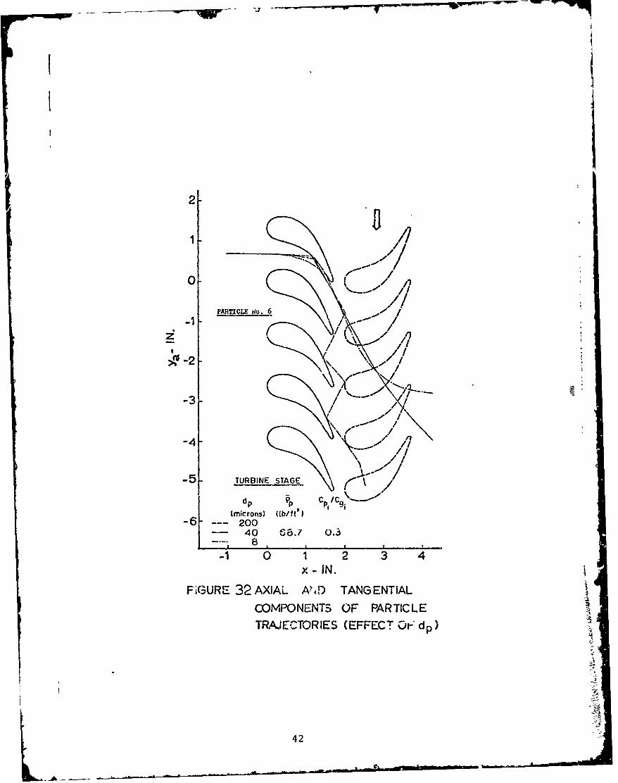
32 Axial and Tangential Components of ParticleTrajectories (Effect of d)p.) ...... ............ .... 42
S33 Axial and Tangential Components of ParticleTrajectories Relative to the Rotor Blades(Effect of dp) ....................... 43
34 Axial and Radial Components of ParticleTrajectories .......... ..................... .. 44
35 Particle Nondimensional Absolute Velocities(Effect of d)p.) ........ .................... .... 44
36 Particle Velocity Diagram, ..... ............... ... 44
37 Axial and Tangential Components of ParticleTrajectories (Effect of dp) ...... .......... . . . . 45
38 Axial and Tangential Components of ParticleTrajectories Relative to the Rotor Blades(Effect of d)p.) ........ ................ ...... 45
39 Axial and Radial Components of ParticleTrajectories .......... ..................... .. 46
40 Particle Nondimensional Absolute Velocities(Effect of d.p.) ....... ................ ...... 46
Li iii,

II
Figure Page
41 Particle velocity Diagram ...... ............... .. 46
42 Axial and Tangential Com2onents of ParticleTrajectories (Effect of p p.) ..... .............. ... 47
43 Axial and Tangential Components of ParticleTrajectories Relative to the Rotor Blades(Effect of p) .............. .................... 4i
44 Axial and Radial Components of ParticleTrajectories .............. ..................... 48
45 Particle Nondimensional Absolute Velocities(Effect of pP) .............. .................. .. 48
46 Axial and Tangential Components of ParticleTrajectories (Effect of a)p.) ..... .............. .... 49
47 Axial and Tangential Components of ParticleTrajectories Relative to the Rotor Blades(Effect of p) ............ .................... ... 49
ip48 Axial and Radial Components of Particle
Trajectories .............. ..................... 50
49 Particle Nondimensional Absolute Velocities(Effect of p p.) ............ .................... ... 50
50 Axial and Tangential Components of ParticleTrajectories (Effect of ý ) ....... .............. ... 51
p51 Axial and Tangential Components of Particle
Trajectories Relative to the Rotor Blades(Effect of p) .......... .............. .. .... .. 51
52 Axial -nd Radial Components of ParticleTrajectories .............. .................... .. 52
53 Particle Nondimensional Absolute Velocities(Effect ofp .p) .......... .................... .. 52
54 Axial and Tangential Components of ParticleTrajectories Effect of C p/C g. ............ 53
55 Axial and Tangential Components of ParticleTrajectories Relative to the Rotor Blades(Effect of C c ).. ...... .................. ... 53
pgi
56 Axial and Radial Components of ParticleTrajectories .............. ..................... 54
57 Particle Nondimensional Absolute Velocities(Effect of / )C ......... ................. .... 54
iv

Figure Page
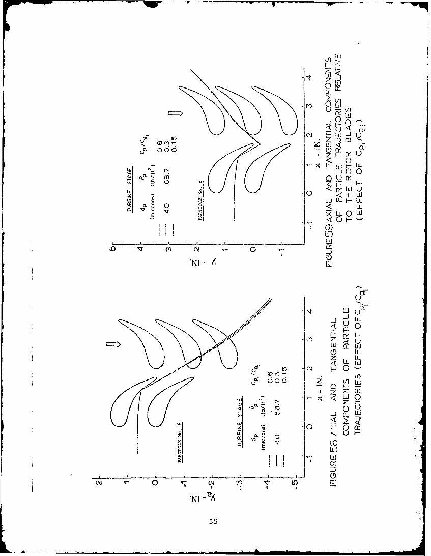
58 Axial and Tangential Components of ParticleTrajectories (Effect of C /C . ..... ............ 55
pi gi59 Axial and Tangential Components of Particle
Trajectories Relative to the Rotor Blades(Effect of C /C )..) ....... .................. .... 55
60 Axial and Radial Components of ParticleTrajectories ............ ...................... .. 56
61 Particle Nondinmensional Absolute Velocities(Effect of C pi./C....) ...... ................ ..... 56
1 1
62 Axial and Tangential Components of ParticleTrajectories (Effect of CIC )/c ............... .. 57
63 Axial and Tangential Components of ParticleTrajectories Relative to the Rotor Blades(Effect of Cpi )IC ....... ................. .... 57
64 Axial and Radial Components of ParticleTrajectories ............ ...................... .. 58
65 Particle Nondimensional Absolute Velocities(Effect of C piC/C)g.. . ..... .................. .... 58
V
IA

1
SNOMENCLATURE
f aparticle concentration; the ratio between weight flow rate of
particles and mixtureangle betwieen particle relative velocity and tangent to surface
SB frame fixed in blades (Figure 3)
B 0 origin of B in Figure 3
C absolute gas velocity
gSC pabsolute particle velocity
C1 gas absolute velocity component in the x,e plane
Cp particles absolute velocity component in the x,O plane
C P specific heat of gas at constant pressure
I modified sream function (Equation (47))
I D5 drag force on spherical particles
dA increment of surface area of particle (Equation (16))
[ dp particle mean diameter
Ax spacing between adjacent points in the meridional direction
Figure 14
A8 spacing between adjacent points in the tangential direction
Figure 14
At increment of time
E frame fired in the engine (Figure 3)
I E origin of E (Figure 3)
e,el 1 e 2 unit vectors (Figure 2)
angle bettieen relative velocity and meridional plane (Figure 11)
coordinate curves in polar coordinates (Figure 2)
the angle to any vector in the plane (r, j ,2) (Figure 2)
G coefficient inversely proportional with the particle charac-
i teristics time (Equation (28))
vi

g(Re) Reynolds number dependent function (Equation (6))
h normal stream channel thickness (blade height) (Figure 4)
1 unit vector in the direction of blade rotation (Figure 10)
angle between meridional streamline and engine axis (Figure 10)
m mass of one particle (Equation (23))p
P 9 gas viscosity
nl,,n2,n3 unit vectors in the direction of the coordinate curves x, 0, z
NI,N,N 3 unit vectors in the direction of the axes X, Y, Z
0 particle center (Figure 2)
p pressure at a point
P total pressure on a spherical particle
R blade mean radius (Figures 3 and 4)
Re Reynolds number (Equations (13) and (14))
r polar coordinate (Figure 2) or radius from axis of rotation
(Figure 10)
Pg gas density
p p particle material density
s blade angular spacing
T gas temperatureg
U blade speed at the mean radius (Figure 13)
u gas relative velocity component in the x-directiong
u particle relative velocity component in the x-directionp
V gas relative velocityg
V particle relative velocityp
pt gas relative velocity component in the x,O plane
SVI pricle relative velocity component in the x,e plane
v gas relative velocity component in the tangential directiong
v particle relative velocity component in the tangential direction.p
vii

W weight flow rate of mixture per channel
w particle relative velocity component in the radial directionp
W blade angular velocity
x,e,z coordinate axis in the meridional, tangential and radial
direction, fixed in B (Figures 3 and 4)
X,Y,Z axes fixed in engine (Figures 3 and 4)z particle velocity components measured in B
x,O,z particle acceleration components measured in B
X,Y,Z absolute velocity measured in E
X,Y,Z absolute acceleration measured in E
! y distance measured along the tangential direction
outer normal to boundary (Figure 1i)
Subscripts
a absolute trajectory
g gas
i initial conditions at particles entrance
in conditions at the boundary AH (Figure 14)
n normal to •.urface
0o total conditions
out after cascade
p particle
t tangent to surface
x in the x-direction
y in the y-direction
z in the z-direction
1 before collision
2 after collision
viii
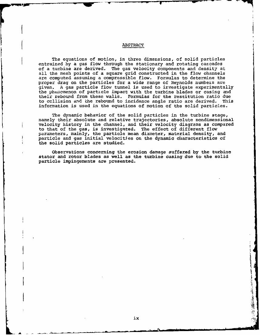
ABSTRACT
The equations of motion, in three dimensions, of solid particles
entrained by a gas flow through the stationary and rotating cascadesof a turbine are derived. The gas velocity components and density atall the mesh points of a square grid constructed in the flow channelsare computed assuming a compressible flow. Formulas to determine theproper drag on the particles for a wide range of Reynolds numbezs aregiven. A gas particle flow tunnel is used to investigate experimentallythe phenomenon of particle impact with the turbine blades or casing adtheir rebound from these walls. Formulas for the restitution ratio dueto ccllision and Lhe rebound to incidence angle ratio are derived. Thisinformation is used in the equations of motion of the solid particles.
The dynamic behavior of the solid particles in the turbine stage,namely their absolute and relative trajectories, absolute nondimensionalvelocity history in the channel, and their velocity diagrams as comparedto that of the gas, is investigated. The effect of different flowparameters, mainly, the particle mean diameter, material density, andparticle and gas initial velocities on the dynamic characteristics ofthe solid particles are studied.
Observations concerning the erosion damage suffered by the turbinestator and rotor blades as well as the turbine casing due to the solidparticle impingements are presented.
ix
I LX

INTRODUCTION
Rockets, aircraft engines, and industrial gas turbines operatingin desert or dusty areas and in places where the atmosphere is pollutedby small solid particles from factories and car exhausts can be examplesof machines operating under gas particle two phase flow conditions.Another example is engines that burn fuels which produce solid particlesin the products of combustion. The solid particles mixed with the in-let air or combustion gases, due to the difference in their inertia,will be driven away from the streamlines of the gas and impact with thesurrounding walls of the engine. The presence of solid particles in thegas stream constitute a possible cause for severe erosion damage to theengine parts. The erosion damage caused by solid parti-les is expectedto be more severe in the rotating parts of the engine, where the particlevelocities and frequency of impacts, as well as the flow temperature,are higher. Hence, turbines, axial or centrifugal, of rockets or gasturbines are parts of the engine critically subjected to solid particleerosion. For example, in some instances the life of a turbine of ahelicopter engine is decreased by one-fourth due to its operation ina solid particle suspension as compared to engines operating undernormal conditions. This gives an indication to the seriousness of theproblem from the economical and reliability points of view. The rateof erosion damage to the blades of the stator or the rotor of turbinesis a function of the blade and particle materials, the gas conditionsin the channel, the angle of impact of the solid particles with theblade surface, the velocity of impact and the frequency of collisions.In rotating turbomachinery the centrifugal forces acting on the par-ticles, due to its motion in a circular path, tends to force the solidparticles to move radially, and hence, impact with the turbine casing,causing it to also suffer from erosion damage. Furthermore, the reboundof the particles from the casing wall will increase the frequency ofcollisions with the blades. This discussion points out the fact thatthe solid particles motion in a rotating turbomachine is a three-dimensional problem.
In order to further understand the erosion phenomenon of rotatingturbomachines, it is important to study the dynamic characteristics orbehavior of the solid particles entrained by the gas flow through thestages of turbines. By the dynamic behavior, it is meant, the absoluteand relative position of the solid particles everywhere in the channels,the velocity history and velocity diagrams of the particles as well asa description of the collision and rebound mechanisms of the solidparticles from the blade and casing walls. The particles trajectoriesstudied in rotating turbomachinery furnishes information for correlatingexperimentally determined erosion severity of blades and the character-istics of particle impact on surfaces. It also helps to predict theerosion of proposed cascade designs based on the correlation resultsand thus initiate means to protect blades and walls by minimizingerosion damage. In fact, the investigation of the solid particlesdynamic behavior will enable engineers to design turbines and com-pressors to minimize erosion as well as to optimize aerodynamiccharacteristics.
This investigation was devoted to studying the dynamic behavior of
1

I,solid particles in a turbine stage. The effect of differept flowparameters such as particle mean diameter, material density andinitial particle and gas velocities on the particle dynamic behaviorare investigated. Results of this study are then used to. make ob-servations concerning the areas of the blades or casinig that aresubjected to more impacts and hence, highec rates of-erosion damage.
The three-dimensional equations of motion of solid particlesmoving in a compressible gas stream in a rotating cascade of aturbomachine are derived in a general form. They are solved ,to determinethe particle trajectories an.. velocities in an axial or radial rotatingturbomachinery or any similar three or' two-dimensional particulate flowproblem as special cases. In order to derive and solve the equations ofmotion in the three-dimensional space of solid particles, several as-sumptions concerning the analysis have to be made. Also bassic inf6rma-tion about the impact and rebound phenomenon, drag on particles, and
gas properties has to be investigated.
It is assu:ied that the particles enter the staEor of the turbineor compressor with uniform properties and equal distances apart. Theparticles are assumed to be spheres of constant average mean diameteruniform material density and small in size. The forces acting on thesolid particles causing their motion in the flow are assumed to be
I mainly the drag forces exerted on them by the gas. It is furtherassumed that the presence of solid particles does not alter the gasproperties from that for the case of gas flow alone passing throughthe same cascade. This assumption is more iealiszic for higher par-ticle material densities a~nd small particle concentrations. Theparticle concentration a, is defined by the ratio of mass flow rate, ofparticle to the rate of mass flow of the mixture. Higher materialdensities implies smaller number bf particles for the same concentration.
After particles impact with the blade or casing, they suffer aj drop in their velocities and a change in their direction. In order to
study the impact and rebound phenonienon, a simple test facility isdesigned, where particles and blades of the same materials as in actualoperating conditions are used. Particles are injected into the flowin the test section and photographed by a high-speed camera. Analysisof the high-speed photography of the collision phenomenon gives therestitution ratio and --he ratio of the rebound to the inci-Ience angleas a function of the incidence angle. These two ratios, or anyequivalent ratios, are sufficient to define the mechanism of impactfor a certain particle-wall material combination. From these ratios,the relative velocity and the di',tion of motion of the pa"ticleafter collision are computed and used as the initial conditions to thesolution o- the governing equations of motion for the partic~es;
The drag coefficient on spherical. particles has to be known forthe practical range of the Reynolds numbers based on particle meandiameter and the magnitude of the difference in gas and particle.velocities. Analytical relations to determine the drag coefficienz asa function of the Reynolds number may be derived from the solution ofthe Navier-Stokes equations, which are valid for Reynolds numbers upto 4. Empirical formulas that fit the experimental results for thedrag coefficient on spheres moving in a stream of air are 6erlved up
I 2

to the practical limit of the Reynolds number of such types of flows.These formulas permit accurate calculations of the drag forces actingon the particle and increase the range of application of the equationsof motion of solid particles.
The remaining information that has to be known before solvingthe particle equati.ons of rotion are the gas properties, mainly itsdensity and velocity components everywhere in the channel. The equationsof mocion of a compressible gas moving in a rotating cascade are solved.A square grid is constiucted in the channel and the gar properties arecalculated at all mesh points. The gas properties anywhere in thenozzle could then be interpolated. The gas properties arc calculatedat all mesh points in every row of blades and stored on computer magnetictape'in groups of data each representing a cascade row that constitutesthe sýages of the turbine.
The equations of motion of the particles are formulated with re-spect to axes fixed in the blades at the entrance of the cascade row.Withthe impact phenomenon well described, and the drag coefficient andgas properties known, the equations of motion of the particles are solved.One row of blades is considered at a time, the particles enter the rowwith known initial conditions, hit the walls and rebound (several re-bounds may occur) until they leave the nozzle. The particles outletconditions constitute the initial condition for the successive row.The equations of motion of particles with respect to a new frame ofaxes using the known initial conditions are solved using the correspond-ing gas conditions in the new cascade row and so on. The particlespositions are referred to tie initial axes by a simple transformation.Repeated solution of the equations of motion of the particles for allsuccessive cascade rows gives the particles dynamic behavior throughoutthe turbine. The absolute trajectories of the particles show its realpath, while the relative trajectories indicate its path relative to therotor. This information can be used to determine the erosion rate,knowing the momentum loss duc to impacts and their frequency at a certainarea. he .arizi es veaira- as coznaref to z..= gas veiccitydiagrazi of a s-ae= 'oud illustrate the general behavior of the particles
and their deviations from the gas at inlet and exit ports.
I The study of particles trajectories in flow fields such as nozzles,pipes and cyclones are reported in many articles (References 1-5). How-ever, none of these investigations solve the .. ree-dircnsional problem,or take the collision of particles with the walls or the rotating cascadetype problem into consideration. In References 6, 7, and 8 experimentaland theoretical studies are made by the author, to study or simulate thedynamic behavior of solid particles. The results of the two-dimensionalexperimental study of Reference 6, the theoretical study of Reference 8and the results of this investigation seem to agree with the physicalobservation of eroded cascades of tested and real engines. The resultsof this investigation provide an understanding of the behavior -r theparticles in the rotors, a contribution that was difficult to accumplishby the simulation of Reference 7. The computer program used in the studyis given by the authors in Reference 9. It can be used with slightmodifications to calculate particle trajectories and velocities in twoor three dimensions, stationary or rotating axial or radial turbo-machinery.
3

FORCES ON SPHERICAL PARTICLES MOVING IN A GAS STREAM
The forces that act on solid spherical particles suspended by thegas flow are the drag force, the force due to the pressure gradient inthe fluid surrounding the particles, the force to accelerate the apparent
mass of the particle rel.Ative to the fluid, the Magnus force, and th'aBasset force that takes into account the deviation in the flow patternfrom steady state, see Reference 10. Newton's law of motion may be usedto descr..be the particle motion, where the sum of the forces acting onthe particle plus its inertia force vanishes. The force on a smallparticle suspended in a turbulent flow is given in Reference 11. Furtherdiscussions of the problem are reported in References 12, 13 and 14. Itis assumed that the particles are spherical in shape, so that the dragforce may be calculated using the Stokes drag coefficient, however, cor-rection to the value of the drag forces at higher Reynolds number isintroduced. It is further assumed that the particles are small whencompared to the smallest wave length of the turbulence, hence the effectof particle motion due to shear flow is neglected. Since in the caseof particulate flow problems in gas turbines, the particle mean diameteris small and the density of particle material is much higher in magnitudethan the gas density, the force due to pressure gradient, the force toaccelerate the apparent mass of the particles and the Basset force maybe neglected compared to drag force (Reference 10). The drag force andforce due to pressure gradient acting on a spherical particle are dis-cussed herein, however, the equations of motion for the particles aresolved taking only the drag for-e into account.
Drag Force
An analytical solution of the governing equations of motion for agas flow around a spherical particle is available only for vecy slowmoving particles, i.e. for small Reynolds number.
To determine the drag force acting on the solid particles, considerthe motion of a spherical particle in a steady, slow moving, incompressiblegas flow. If the inertia forces can be neglected compared to the viscousforces, and for no body forces, the Navier-Stokes equations become;
grad p = V V2 (Cg) (1)
The continuity equation of the gas may be written as
Div (C) =0 (2)
The solution of Equations (1) and (2) (References 8 and 15) yieldsthe total drag force acting on the spherical particles for Reynolds numberless than 0.1 as;
D=3 g dp C (3)
If the particle is moving with an absolute velocity Cp in a streamof gas moving with an absolute velocity Cg, the drag force on the spherical
4

particle may be written as;
D=3 i g dp (Cg - Cp) (4)
For higher Reynolds numbers, Equation (4) connot be consideredvalid, a correction factor for this equation which is a function ofthe Reynolds number was introduced (References 8 and 15).
The modified version of Equation (4) may take the form,
D = 3 a •g dp (Cg - p) g(Re) (5)
whezeRe CD
g(Re) = CD Re - D (6)
0
In Equation (5) the Reynolds number dependent function g(Re) hasdifferent forms depending on the range of the Reynolds number. It shouldhave a value of one for Reynolds numbers less than 1.0. Its value canbe determined theoretically from the solution of the Navier-Stokesequations for Reynolds numbers up to 4. The experimental data for dragcoefficients on a sphere has to be used to determine g(Re) for Reynoldsnumbers greater than 4 and within the practical limit of Reynolds numberfor particulate gas flow in turbomachines. Equation (6) shows that thefunction g(Re) can be given as a ratio between the drag coefficient atany Reynclds number and the Stokes drag coefficient at small Reynoldsnumber.
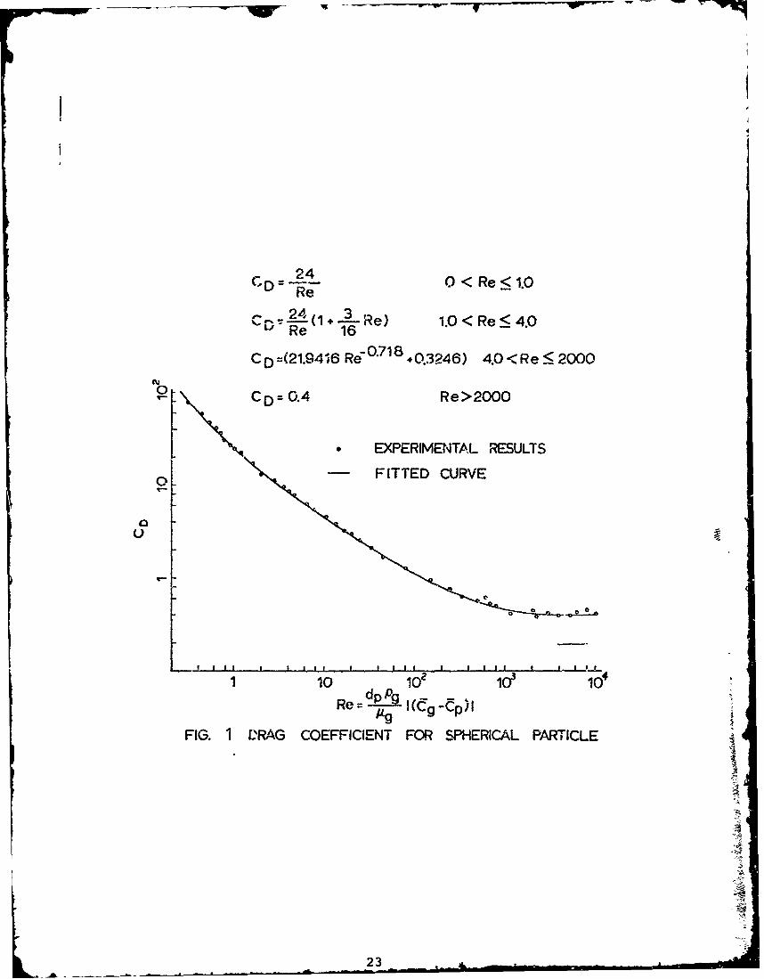
The formulas for the drag coefficient for spherical particles asdefined in Equation (6) are given below for different ranges of theReynolds number.
CD = 24 0 < Re < 1.0 (7)
A solution of the Navier-Stokes equations of motion of a solidparticle using a higher order term gives,
24 3_CD = (1 + - Re) 1.0 < Re < 4.0 (8)
Re 16
The expe-rimental data given by Schlichting (Reference 16) for thedrag coefficient of spherical particles are fitted (Reference 17) with acurve of the type
by = a x + a (9)
where
2Yl Y2 - Y3 (10)
Yl + Y2 - 2Y3
5

., - -- i, , . . . .
f The resulting drag coefficient formula is given by
CD = 21.9416 Re -0.718 + 0.3240
4.0 < Re < 2000 (11)
For higher Reynolds number one may write,
CD = 0.4 Re > 2000 (12)
The Reynolds number in Equations (7), (8), (11) and (12) is basedon the particle mean diameter and the magnitude of the particle velocityrelative to the gas or,
Re I(Vg - ) P ( I¢ (13)I g Pg
or -,
Re--2---2 2 + (v 2 +(w jU )y)+)2 (14)9g g
Figure.. 1gives the fitted drag curve as compared to the experimental
results anq it shows good agreement.
Force Due to Pressure Gradient in the Flow Around the Particle
In order to evaluate the force acting on a spherical particle dueto the pressure gradient around it, consider a spherical particle ofdiameter d and center 0 in a flow field (Figure 2). The pressure at anypoint on tEe particle surface is p(dp/2, 01 , 02) and the pressure at 0is pc. The polar coordinates r, qi and *2 originate from the sphere'scenter. The coordinate Ol is measured from the direction of the gradientvector of the pressure at the center (Vp)o. The vector e is a unit vectorfrom the center of the sphere to any point p(dp/2, ý1, 02). Also el ande2 are the unit vectors in the direction of (Vp)o ana any normal to it thatmakes an angle (02 - *o) from the projection of E on the plane Oi = w/ 2 .
The pressure p(%/ 2 , *l' ý2) at any point on the surface of thesphere is given by
d d
P ~P (-2 ' =1 0) Po + .P-2
d= P0 + 2-- [(Vp) 0 " e]
6

-• - -• ;" • '• • -
or
p = p0 + 2 I(vp)o cos (15)
The total force acting on the particle, P, equals the sum of thesepressure forces on the surface of the sphere, i.e.
r=f (p e) dA (16)
where dA is the increment of area of the surface of the sphere whosenormal is Z. Using Equation (15), Equation (16) may be rewritten as
d3 27r -,
P9 = 8 j(Vp)oI f I e sin o c1 ' Co (d 0 (d 02) (17)0 0
The component of P in the e1 direction is P1 given by
2nn 2
1 = 8 : (Vp)ol f f sin O1 cos 01 (d 01 )(d 02)0 0
or d3
P1 = 6 I(Vp)ol (18)
The component of P in any direction e2 perpendicular to i 2and may be given by
d3 2
2= o8p I(Vp)0 r Cos (02 - *00(d "20Tr 2
I sin 01 cos Oi (d ) 0 (19)0
Since P2 vanishes for any arbitrary direction e2, the force P isthen in the direction of e1 , i.e., the direction of the vector (Vp)O andis given by
p =; (p e) dA = (Vp)
' -- (Vp) 0 (20) jpP
7
POW|
where mP and (mp/pp) are the mass and volume of one particle, respectively.
Using Euler's equation of motion for the gas, the force P, acting on
the particle due to the pressure gradient may be written as
m ((-p- (vp)o0 = mp (L2 ( Vag (21)
I p- g g
EQUATIONS OF MOTION OF SOLID PARTICLES ENTRAINED
3 BY THE GAS FLOW IN A ROTATING CASCADE
The turbine may be divided into separate successive rows, forexample, stator, rotor, stator, etc. The particles are assumed to enterthe first row with their initial conditions referred to a system of axesassociated with the first row. The conditions of the particles at the
I outlet of the first row may be transformed to another set of axes as-sociated with the second row of blades, stationary or rotating, andthese will be considered initial conditions for the second cascade row and
Sso on, until the particles leave the turbine with the conditions at theexit of the last cascade row. In order to derive the equations of motionof the particles suspended by the gas flow, their motion through a ro-tating cascade row is considered, with the case of particle motion in astator blade row, following as a special case. It is convenient to de-fine systems of axes associated with each cascade row to simplify thecomputer programming problems, as well as yielding a simpler set of
I equations of motion for particles in the rotor blades.
For convenience, the following axes systems are defined. B is aframe fixed in an arbitrary blade of the rotating cascade with nl, n2and 3 as a set of nonparallel, noncoplaner, right-handed unit vectorsin the direction of the coordinate curves x, 0 and z, respectively, asshown in Figure 3 And 4. The point Bo is the origin of the frame B,F which is taken at the intersection of the plane tangent to the blade rowat the entrance and the blade axial chord in the mid-stream surface ofrevolution of radius R that passes through the middle of the blade
I height. The coordinate curves x, 8 and z are in the axial or meridionaldirection, the tangential, and the radial directions, respectively.Further, it is assumed that the frame B, fixed in the blade row, moveswith a constant angular velocity w, equal to the angular speed of therotor, in a reference frame E fixed in the engine. The mutuallyperpendicular set of axes X, Y and Z, are fixed in the engine at apoint Eo. Point Eo is the intersection of the engine axis with the
I plane tangent to the blade row at the entrance. The coordinate axis. X is in the axial direction, while Y and Z are axes normal to the X axis
in the plane tangent to the blade row at the entrance, as shown inFigures 3 and 4.
"Consider the motion of a solid particle entrained by the gas flowpast a rotating cascade. Referring to Figure 5, the coordinate curves
ex, and z, that rotate with an angular velocity w, after a time t, areat an angle equal to wt from the Z axis. The particle p is aL any
8

t--
-
arbitrary position x, 0 and z measured from BO.
According to Newton's law of motion the forces acting on theparticle, taken to be the drag for-!e, equals the mass of the particlemultiplied by its acceleration in an inertial reference frame. Theequations of motion of the particle p with respect to the axes X, Yand Z of the fixed reference frame E are
mx=D%Mpp xy
mpi, p D z(22)
where m is the mass of one particle given byP
1 3 •(23)MP =p 6" d PPp
and Xp, Yp and ip are the second derivatives with respect to time ofthe components of the position vector of p in E.
From Equation (5) the components of the drag force in the referenceframe E, as given in Equation (22) are written as
DX = 3 v1 dp g(Re) (kg- XI)
Dy = 3 r g d g(Re) (Y - Y
DZ = 3 9 •g dp g(Re) (g - Zp) (24)
In Equation (24) kg, Yg and Zg are the gas velocity components atp in E, while kp, Yp and .p are the velocity components of a particle atp in E.
Substituting Equatiors (23) and (24) into Equation (22) we get
Xp = G(X - A ) (25)
L = - )2•p G(g .p)()
,p *•g •p) 2- -7
£i
!_9

-+, ..... _ ___ ____ __ I,__ - + .... . ,I -- - -+ + + ,
where
G - g ( He) (28)
2-ddp Up
The coefficient G is a measure of the particle characteristic timewhich indicates the relaxation time of the particles relative to thegas flow.
From Figure 5, the relation between the components of the positionvector and its first and second derivatives with respect to time measuredfrom EQ and the components of the position vector and its time deriva-tives measured from Bo of the particle p, is given by
X=X k=x X x (29)
Y = (R + z) sin (0 + wt)
S= z sin (0 + wt) + (R + z)(0 + w) cos (6 + wt)
Y = sin (0 + wt) + 2i (6 + w) cos (0 + wt)
+ (R + z) ( + w) 2 sin (B + wt) + ; cos (0 + wt)] (30)
Z = (R + z) cos (0 + wt)
= cos (0 + wt) - (R + Z) (6 + d) sin(e + wt)
z z cos (0 + wt) - 2Z (6 + w) sin (0 + wt)
- (R + z) [(6 + w) 2 cos (0 + Wt) + 0 sin (0 + wt)] (31)
The velocity components of the gas at any point p with referenceto E0, neglecting the gas velocity in the radial direction comparedto the gas velocity in the axial and tangential directions, are writtenas'
g = �gg
"Yg = [v + (R + z)wl cos (6 + wt)
.g = [V + (R + z)w] sin (e + wt) (32)
where ug and v are the components of gas velocity relative to therotating bladeg in the axial and tangential directions, respectively.
Substituting Equations (29), (30), (31) and (32) in Equations (25),
10

1 (26) and (27), find
x G (u-) (33)
z si.n ( + wt) + 2z (6 + w) cos (e + wt)
- (R + z)[ + w)2 sin (8 + wt)
+ 0 cos (3 + wt)] = G{[v g + (R + z)w] cos (0 + wt)
- sin (A + wt) (R + z)(6 + w) cos (0 + wt)) (34)
z cos (0 + wt) - 2i (5 + w) sin (0 + wt) - (R + z)
[(6 + W)2 cos (0 + Wt) + 0 sin (0 + wt)]
= G{[vg + (R + z)wl] sin (O + ct) - z cos (O + wt)
+ (R + z) (6 + w) sin (0 + wt)) (35)
Multiplyis4.7 Eyuation (34) by cos (0 + wt), Equation (35) bysin (0 + wt), and Rubtracting the two resulting equations and rearrang-ing, we get the .quation of motion of the ?article p in the tangentialdirection as
(R + z)e = G[Vg - (R + z) 6 ] - 2i (6 + w). (36)
Multiplying Equation (34) by sin (0 + wt), Equation (35) bycos (0 + wt), and adding the two resulting equations and rearranging,we get the equatioz. of motion of the particle p in the radial directionas
z G - + (R + z) (6 + )2 (37)
The distance y that a particle travels in the 0 direction on thesurface of revolution with radius (R + z) is given by
y = (R + z) 0 (38)
For convenien,;e Equations (33), (36) and (37) may be rewriteen as
x=G (u -k) (39)
(RG [v ( )1 2i +) (40)0 R T [Vg - + z+ z))] - (R + z)
z = - G i + (R + z) (• + w)2 (41)
11-

Re and G are given by Equations (14) and (28), respectively.
Equations (39), (40) and (41) are the governing equations ofmotion of any particle p moving with the gas stream through the nozzlesof a rotating cascade. They represent the equations of motion iii theaxial, tangential and radial directions, respectively. The coordinatecurves x, 8 and z measured in the frame of axes B and their first and6econd time derivatives as well as the relative gas velocity componentsin the axial and tangential directions are taken at the particular pointunder consideration. It .s noted that the second term in the right handside of Equation (40) represents Coriolis acceleration, while the secondterm in the right hand side of Equation (41) represents the centrifugalaccelerations of a particle moving in curved path in the rotating frameB. (References 18 and 19). These equations form a system of nonlineardifferential equations. They are solved numerically for every particleentering the cascade in increments oi time if the initial conditions ofthe particle are known. The time increment may have a constant valueas long as it does not take the particle beycnd the wall, thus, at theregular increment nearest the wall, the time increment has to be iteratedto the exact value that is necessary for tLe particle to just hit thewall. Solution of the general system of equations of the type of Equa-tions (39), (40) and (41) and a discussion of the error are given inReference 9. The solution of the partic~le equations of motion givesthe relative and absolute locations as well as the velocity componentsof a particle in the rotating cascade row. Successive solution of theseequations for every ca3cade row will give the particles path throughoutthe turbine. The solution of these equations requires the knowledge ofthe coefficient G, the collision and rebound mechanism of the particlesand the turbine walls as well as the gas properties in the channel.
EXPERIMENTAL STUDY OF THE IMPACT AND REBOUND
PHENOMENON OF SOLID PARTICLES FROM THE WALLS
When a solid particle moves in a stream of gas, it does not in generalfollow the streamlines taken by the gas due to its higher inertia. Forparticulate gas flow passing through the nozzles of a rotating cascade,the particles tend to collide with the blade surfaces. They often collidewith the turbine casing due to the effect of the centrifugal force act-ing on the particle. After hitting the walls, the particles experiencea loss in their momentum relative to the wall and change the directionof their motion. They may hit the blades one or more times beforeleaving the cascade. These repeated collisions of several particlescauses severe erosion damage to the blades. The analytical study ofthe impact phenomenon of particles with a rotating blade in threedimensions is a very difficult task. The value of the particle velccityand direction of its motion as it rebounds from the surface aftercollision must be known in order that the solution of the particleequations of motion be continued beyond the points of collision. Inorder to investigate the collision phenomenon, an experin ntal studywas made, where the particles were photographed and their behaviorduring this process is studied. The experimental facilities of Reference15 were used and extensive results for steel blades and corn cups particles
12

--
have been collected and analysed so as to determine the behavior of solidparticles before and after the collis:on with the walls. The result ofthis study is given in details in References 8 and 15 and may be summarizedas follows.
The change in particle momentum ý::e to collisions was found tobe mainly a function of the particle incidence angle 81. In Figure 6,the ratio of the particle 'velocity tangent to the surface after andbefore collision (V pt2/V pt) is plotted versus 01, and may be considered
constant for all particle diameters. Thw. dotted line in Figure 6represents the straight line fitting the experimental data expressedby the equation,
V / V = 0.95 + 0.00055 81 (42)
Pt2 Ptl1I
The change in the ratio betwetz particle velocity components normalto the surface of the blade aftex and before collision (V pn2/V pnl), as a
function of 81, is given in Figurce 7 for different particle diameters.
The dotted curve in Figure 7 represents the curve fitting of the datapoints on the figure expressed by the following relation
, VSPn2 2V 2 1.0 - 0.002108 81 + 0.0001417 81 (43)
Pnl'
The restitution ratio (V p2/Vpl ) is defined as the ratio between
the particle velocities after and before collision. Anoher importantfactor is the rebound to incidence angle ratio (82/81), defined as theratio of the angle between the direction of the incidence particlevelocity and the tangent to the surface at the point of impart and theangle between the direction of the rebound particle velocity and thetangent to the surface at the same point.
Figure 8 gives 82/81 as a function of 8a. The dotted curve isobtained by substituting Equations (42' and (4 3 ) into the followingrelation.
82 1 o- [ . cot (44)1 81 Ptl Pn2
In Figure 9, the restitution ratio is presented versus 8j. Equa-tions (42) and (43) together with the following equation are used toplot the dotted curve in the figure.
V V : 2P2 Pn2 l+cot 2(5
-- _ ... 2 (45)vpl Pn + c2 13

Once the particles and blade materials are known for a certain gasturbine application, fundamental experiments can be conducted to renderinformation about the impact and rebound phenomenon of this particularmaterial combination. It may be added that in order to simplify theanalysis the formulas found to describe the impact phenomenon do nottake into account any deposits or wear that may be suffered by the bladematerial due to collisions. Either Equations (42) and (43) or Equations(44) and (45) are enough to define the particle condition just afterrebound from the surface. They give new initial conditions to be used inthe solution of the equations of motion of the particles after collision.
GAS FLOW PROPERTIES IN A BLADE TO BLADE SURFACE
OF REVOLUTION OF A ROTATING CASCADE
The assumption that the gas flow moves in the blade to bladesurface of revolution shown in Figure 10, is applicable to axial orradial flow cascades. The coordinate curves x, 8 and z are fixed inthe blade as described earlier, in general they are in the meridionaldirection, tangential and normal to the blade to blade surface ofrevolution. It is required to determine the properties of the com-pressible gas flow, namely the gas density, pg, and the velocitycomponents in the meridional and tangential direction, uq and vg, inboth the rotating channels of the cascade and on the blades. Asolution to the momzntum, continuity, energy and state equations thatconveniently describe the gas flow in a rotating cascade provide thegas properties required in the solution of the governing equations ofmotion of the particles. For small particle concentrations it can beassumied that the gas conditions calculated from the solution of thenonparticulate gas flow equations of motion in a rotating turbomachineare not going to be altered due to the presence of particles in theflow.
For a compressible, nonviscous and steady gas flow, the momentumand continuity equations (References 15 and 20) may be written as,
2xxT 22 []aa' 2 +1 _2 sin A 1 1hp9 Dr r h p ax axr a8 g
- 1 g` - W sin ) (46)r2 ae ae WAtr A
Pg1Awhere
W a'?Ug = rhW
vg h a' (47)h1P ax
g
14L- A

' is the modified version of the stream function.
The combined energy and state equation is
1
R 2 Y-l1 (48)
Pg. = i (• g.T ) 8
Pgin Pg gin
The turbine cascade channel region ABCDEFGH in Figure 11 isdivided into square grids, the difference equation (Reference 9) ofEquation (46) is written at all thc mesh points. A solution by themethod of over-relaxation (Reference 21) to the n resulting algebraicequations is obtained using assumed initial values for the gas density,say the absolute total density at inlet. The solution of these equa-tions gives the modified st;:eam function at the mesh points. Theapproximate relative gas ve:locity components at all the mesh pointsare then calculated from Ecquations (47). Equation (48) may then beused to compute new gas densities at the mesh points. These newdensities are used to determine a better approxi'aation for the modi-fied stream function and hence the relative gas velocity, which arethen used to determine new gas densities and so on , until the requiredaccuracy in calculating the gas density is reached. The fortranprogram Reference 22 is modified slightly to give the relative gasvelocity components and densities at the mesh points, by solvingLuations (46) and (48) then store the data for a cascade row onmagnetic tape, to be used as data in the solution of the particleequations of motion. Other methods to determine the gas propertiesin the cascade by placing singularities on the contour of the airfoil(Reference 23,, or by distributing the singularities on the camberand chord lines (Reference 24) may be used. The gas flow in thesecases is considered incompressible and correction for the compres-sibility effect has to be introduced (Reference 25). Another method(Reference 26) gives the compressible gas flow properties for a sub-sonic cascade flow by the method of distributing vorticities along theblade contour. The advantage of using a square grid is that it maybe used as a means to specify the particle location in the channel.The decision on which method to use to determine the gas propertiesshould be a compromise between accuracy, range of application andcomputer time.
NUMERICAL EXAMPLE
The dynamic characteristics of particles entrained by a gasthrough a turbine stage consisting of a stator followed by a rotoris considered herein. The effect of different particle and gas flowparaiieters on the particle characteristics are investigated. Thepareaneters considered are the particles mean diameter, their materialden:Ai-y and their initial nondimensional absolute velocity, as well asthe gas velocity at the inlet. The particle trajectories and velocitiesP..e calculated from Equations (38), (40) and (41). The drag coefficient
S~15

is calculated using Equations (7), '(8), (11) and (12), the impact andrebound characteristics from Equations (44) and (45), and the gasproperties in the cascade are obtained by solving Equations (46) and(48). The computer program described in Reference 9 is used on theIBM 360 computer, and the output punched on cards. These cards arefed as an input to the Calcomp plotter which is programmed through theIBM 1130 computer to plot the trajectories- and velocities of theparticles.
Particles Dynamic Behavior in the Turbine Stage
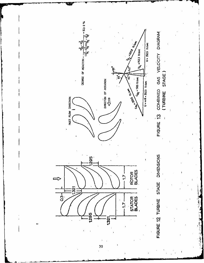
The dimensions of Lhe stator and rotor of the turbine stage aregiven in Figure 12, while the dirfoil dimenslions are given in Reference 27.Figure 13 illustrates the combined gas velocity diagram for the 53.42%degree of reaction turbine stage. The wesh structure used for thecalculation of the gas 'properties and the prticle trajectories is shownin Figure 14. The particles "are assumed to enter the' turbine statorwith uniform velocity. The particle concentration a does not appearin the equations of motion of the particles, hence it does not in,-fluence the behavior of any individual particle for practically smallconcentrations. Associated with certain a, and suspension flow rateare specific spacings between particles, which determine the place andthe frequency of collisions and conseyuently affects the rate of bladeerosion at the different points on its surface. Since the bladerotational speed is much higher than.the particle velocity: at theentrance to the turbine rotor, the position of the rotor blades maybe taken arbitrarily (Figure 12). The dynamic behavior of a groupof five particles of mean diameter dp = 200 microns, entering thestator blade uniformly is shown in Figures 15, 16, 17 anA 18. Inparticular, the projection of the absolute and relative trajectoriesin the stream surface of revolution and the radial displacement andthe nondimensional absolute particle velocity distribution throughthe stage is illustrated in these figures. Similar figures for elevenparticles unifo_•r.ly entering the stator cascade with mean diameters 40microns and 8 ndcrons are given iin Figures 19 to 22 and 23' to *2, re-spectively. Xn the case-of the particles of dp = 200 microns, theresults are only plotted for every other particle in order to facilitateinterpretation of the figures. In Figures 15 through 26, the particlematerial density Pp is 68.7 lb/ft 3 and -the initia] particle absolutevelocity ratio, nondimensionalized with zespeqt to gas inlet velocity,C iC equals 0.3. The gas conditions at the turbine stator inletP g!
are: gas initial veiocity C = 142.64 ft/sec, initial gas density3
P = 0.076 lb/ft , initial gas total temperature T = 6q*F, and thePgin gin
total mass flow rate per channel W = 0.123 lb/sec.; and the particlesenter at the stream surface oý revolution of radius 7.05 inches Thediameter of the turbine is taken relatively small so that the centrifugaleffects on the particles are pronounced and in order to give a moregeneral particle path. The cascade design angular speed at the mid-radius R is taken to be wd = 603.5 radians per second,'which is equivalentto a mid-radius blade velocity of 352.5 ft/sec. From Figures 15 through26 it can be ohserved that as the particle mean diameter decreases, the
16

particles experience less deviation from the gas streamlines in thestator. They tend to enter the opposite rotor blade channel andexperience less scattering in the rotating nozzles (Figures 16, 20and 24). Particles with higher mean diameters hit the blunt leadingedge of the rotor blade and retu-n to the stator, collide with thestator suction surface and return to the rotor. They may repeat the
, same process more than one time, causing erosion of the suction sideof the stator blades (particles number 2, 4, 6 and 8 in Figure 15).The particles enter the rotor when they pick up enough speed to take
S them through the rotor nozzles. The band that contains the particlesas they leave the stator narrows as the particle mean diameter de-creases (compare Figures 15 and 23 for dp = 200 and 8 microns, respec-tively). As the particles mean diameter decrease, they attain higher
Svelozities in the stator and the change in their absolute velocities, ! as they enter the rotor decrease (Figures 18, 22 and 26). Particles
with smaller mean diameters have smoother absolute and relative pathsa; ad velocity distributions, as can be seen from Figures 15 through 26.The velocity distributions of particles with smaller dp, however, are'more affected by the gas conditions, particularly near the stagnationpoints (Figure 26 for particles with dp = 8 microns). Particles tendto move with a higher radial velocity after hitting the rotor blades.The higher the value of d , the higher will be the radial velocitiesof the particles after collision (Figures 17 and 25). The particlesStravel toward the blade tip as they pass through the stage. Those
i particles of dp = 200 microns hit the turbine casing before leaving theturbine stage (Figure 17). Particles with d. = 8 microns, however,travel through the stage without hitting the casing (Figure 25). The
j vertical lines in the relative trajectories of Figure 16 indicate thedistances traveled by the rotor blades during the time taken by theparticles to re-enter the stator, hit the stator blade suction sideand reach the stator exit. These distances differ with the particleinitial position and velocity as it returns to the stator. The loopsin the curves of the particles velocity in Figure 18 are associated
S with the paitic)e3 that return to the stator. These loops result from_ the particles momentum gain due to their collision with the rotor blades,
followed by a momentum loss resulting from their impacts with the stator.I Particles with d. greater than 200 microns; tend to move back and forth-nany times from rotor to the stator and vice versa, until they eitherbreak into smaller particles, or reach the proper speed and directionto go through the rotor. It is also observed from Figures 15 and 16for particles with d = 230 microns and Figures 23 and 24 for particles
S with dp = 9 microns that, particles with smaller mean diameters experiencefewer collisions with the stator and the rotor, particularly on thesuction sides of the blades. "article collisions with the blades dueto their lateral motion are affucted by the cascade geometry, namely,the pitch and blase camber. Other factors that influence these collisionsare the mechanisms of impact and rebound, the cascade rotational speed,and gas and particle prcperties. The parts of the stator blade sub-jected to more impacts, and hence, higher rates of erosion, are theleading edge and pressure side. The stator blade suction side issubjected to impacts only from particles of higher mean diameters that
i return to the stator efter hitting the rotor blade leading edge (Figure.15). In the rotor bJ.ades, the particles hit the blades with higherrelarive velocities, nence, the rate of erosion is expected to be higherthin that for the stator blades. The rotor blade leading edge is erodedby particles of all sizeo, while the pressure side is subjected to
37
collisions only from particles with higher mean diameters (Figures 16,20 and 24). As the particles reach the casing, they impact and reboundin an occilating manner with decreasing amplitude. Finally, theymove into the stream surface of revolution that passes through theblades tips and cause severe damage to blade tips in the later stages.The previous conclusions concerning the blade areas subjected to erosionare in agreement with the observations of actual eroded turbine blades.
In order to study the effects of different particulate flow para-meters on the dynamic behavior of the particles, the particles aredivided into three typical trajectory groups according to their locat-Lonat the time they enter the stator. Figures 15, 19 and 23 or Figures 27,32 and 37 illustrate typical examples of the three trajectory groups.In particular, particles such as number 2 start by hitting the upperpart of the stator blade leading edge, particle number 6 moves straightin the stator channel and hits its pressure side, while particle number10 starts by hitting the lower part of the turbine stator leading edge.
The dynamic behavior of particles having mean diameters of 200, 40and 8 microns, the same material density and initial velocities, isinvestigated. The results are shown in Figures 27 to 41. The effectof particle mean diameter on it dynamic behavior is eiscussed above.Additional figures,showing the combined velocity diagrams of the par-ticles as compared to those of the gas, are given for all of thetypical particles (Figures 21, 36 and 31). These figures illustrate thedifference in the overall behavior between the gas and the particles.In Figures 31, 36 and 41, V' and V' are the particle relative velocity
Pl P2components in the x-e surface at the inlet and the exit from the rotor,respectively, while Cpl and C'2 represent their corresponding absolute
values. The particle radial velocity components are written next tothe corresponding velocity diagrams.
The effect of particle material density, pp, on the dynamicbehavior of the solid particles is sbown in Figures 42. through 53.The dynamic behavior of the three 4ypical particles is shown in threegroups of four figures each for p = 34, 68.7 and 151 lb/ft 3 for aconstant dp = 40 microns and C /9 = 0.3. These particle material
densities approximately correspond to the densities of coal, sand, andsilicon, which are the materials that a practical gas turbine flow maycontain as solid suspension. It may be shown from the above figuresthat a decrease in p will lessen the deviation between the particletrajectory and the gas streamlines (Figures 42, 46 and 50), decreasetheir radial displacements (Figures 44, 48 and 52), and increase theirinitial acceleration (Figures 45, 49 and 53). Since partic.les withsmaller p tend to escape collision with the rotor blades, they ex-perience ?ewer abrupt changes in their velocity as they pass throughthe rotor (Figure 53)
For particles with constant dD = 40 microns and pp 68.7 lb/ft 3
the initial nondimensional absolute particle velocity /C is varied,p. g.
taking the values 0.15, 0.3 and 0.6 to determine the effect of C /C on
18

the particle dynamic behavior. The dynamic behaviors of the threetypical particles are plotted in Figures 54 through 65. These figuresshow that the particle initial speed have a small effect on theirtrajectories, especially in the stator. The partiLles are found toreach the same absolute velocity after traveling relatively shortdistances irrespective of their initially different value of Cpi/Cgi
(Figure 57). The effect of the initial gas velocity on the dynamicbehavior of solid particles may be determined from the figures fordifferent CpiC , bearing in mind that for the same inlet particle
p. g.velocity, higher gas inlet velocity would mean lower C PiCgi , and vice
The particle mean diameter is the parameter tlat has the greatesteffect on the particles dynamic behavior, while pp and C pi/Cgi have
smaller effects. The same conclusion could be arrived at by lookingat the equations of motion of the particles, since d appears raisedto the second power. p
19
4
j
L 19

CONCLUS ION
The dynamic behavior of solid particles entrained by the compressiblegas flow in a stationary or rotating cascade of a turbine is determined.Impacts of the solid particles with the blades and the casing are con-sidered. The equations of motion of the solid particles are solved inthe three dimensional space. The drag forces on the particles arccalculated using drag formulas that fit the drag curve of a sphericalparticle over a wide range of the Reynolds numbers. The compressiblegas flow properties are computed by solving numerically the gas equationsof motion in a blade to blade surface of revolution of a rotating cas-cade. Experimental investigation is made to study the impact and re-bound phenomenon of the particles from the walls, to determine formulasfor the restitution ratio, and rebound to incidence angle ratio. Theseformulas define the particle conditions after collision which are thenused to continue the solution of the equations of motion for the particles.These formulas have to be determined experimentally for every particle-target material combination once the turbomachine operating conditionis known.
The study showed that in general, solid particle paths are deviatedfrom gas streamlines. This deviation increases with increased particlemean diameter, material density, particle initial velocity or decreasedgas initial velocity. The particle mean diameter has the greatesteffect on the dynamic behavior of the particles, while the particlematerial density has a lesser effect and the particle initial velocityhas the least effect.
The turbine stator and rotor blade leading edges and pressure sideswill be eroded by particles of all sizes. The rear part of the statorsuction side will be eroded by larger particles after their re4--rn tothe stator due to their collision with the rotor olades. The turbinerotor is expected to suffer more severe erosion than the stator due tothe higher velocities of the particles in the rotor.
Turbines may be designed to both minimize erosion as well asoptimizing aerodynamic characteristics using the results of this in-vestigation. Means may be introduced to collect or deviate some ofthe particles, expecially those that contribute most to erosion, fromthe blades and hence, reduce erosion damage.
20

REFERENCES
1. Lapple, C.E. and Shiepherd, C.B., "Calculation of ParticleTrajectories," iidustrial and Engineering Chemistry, Vol. 32,No. 5, May 1940, pp. 605-617.
2. Gilbert, M., Davis, L. and Altman, D., "Velocity Lag of Particlesin Linearly Accelerated Combustion Gases," Jet Propulsion, Vol. 25,January 1955, pp. 25-30.
3. Kriebel, A.R., "Particle Trajectories in a Gas Centrifuge,"Transactions of the ASME, Journal of Basic Engineering, Series D,September 1961, pp. 333-340.
4. Neilson, J.H. and Gilchrist, A., "An Analytical and ExperimentalInvestigation of the trajectories of Particles Entrained by theGas Flow in Nozzles," Vol. 35, Part 3, 1969, pp. 549-559.
5. Vitols, V., "Determination of Theoretical Collection Efficienciesof Aspirated Particulate Matter Sampling Propes AnisokineticFlow," Ph.D. Thesis, the University of Michigan, 1964.
6. Tabakoff, W. and Hussein, M.F., "Trajectories of Particles Suspendedin Fluid Flow Through Cascades," AIAA Journal of Aircraft, Vol. 8,No. 1, January 1971.
7. Tabakoff, W., Hamed, A. and Hussein, M.F., "Investigation of GasParticle Flow Pressure and Solid Particle Trajectories andVelocities in an Axial Flow Cascade Pair," ASME Paper No. 72-GT-57,presented at the ASME 17th Annual International Gas Turbine Con-ference and Product Show, San Francisco, California, March 1972.
* 8. Hussein, M.F., and Tabakoff, W., "Calculation of Particle Tra-* jectories in a Stationary Two Dimensional Cascade," Project
Themis Report No. 72-27, University of Cincinnati, Cincinnati,Ohio, 1972, USGRD Report to be published.
9. Hussein, M.F. and Tabakoff, W., "Computer Program to Estimate theDynamic Characteristics of Solid Particles Entrained by the GasFlow in a Rotating Cascade of a Turbomachine," United States Govern-ment Research and Development Report to be published.
10. Soo, S.L., "Fluid Dynamics of Multiphase Systems," BlaisdellPublishing Company, 1967.
11. Tchen, C.M., "Mean Value and Correlation Problems Connectedwith the Motion of Small Particles Suspended in a TurbulentFluid, Dissertation, Martinus Nijhoff, The Hague, 1947.
12. Hinze, J.O., "Turbulence" McGraw-Hill, New York, 1959.
13. Corrsin, S. and Lumley J., "On the Equations of Motion for aParticle in Turbulent Fluid," Applied Scientific Research 6A,114, (1956).
K_ 21

W 4.WPW
14. Lumley, J.L., "Some Problems Connected with the Motion of SmallParticles in Turbulent Fluid," Ph.D. Thesis, johns Hopkins Uni-versity, 1957.
15. Hussein, M.F. "The Dynamic Characteristics of Solid Particles inParticulate Flow in Rotating Turbomachinery'," Ph.D. Dissertation,University of Cincinnati, Cincinnati, Ohio, 1972.
16. Schlichting, H., "Boundary Layer Theory," McGraw-Hill, Inc., 1968.
17. Davis, D.S., "Nomography and Emperical Equations," ReinholdPublishing Corp., 1962.
18. Kane, T.R., "Dynamics," Holt, Rinehart and Winston, Inc., 1968.
19. Marris, A.W. and Stonking, C.E., "Advanced Dynamics," McGraw-HillInc., 1967.
20. Vavra, M.H., "Aerothemodynamics and Flow in Turbomachines," JohnWiley and Sons, Inc., 1960.
21. Varga, R.S., "Matrix Iterative Analysis," Prentice-Hall, Inc., 1962.
22. Katsanis, T., "Computer Program for Calculation Velocities andStreamlines on a Blade to Blade Stream Surface of a Turbomachine,"NASA - TN D - 4525, April 1968.
23. Bueckner, H.F. and Schnackel, H.C., "The Calculation of IncompressibleFlow through Turbine Cascades," ASME Paper presented at the ASME,1959 Annual Meeting, Atlantic City, New Jersey, Nov. 1959.
24. Schlichting, H., "Berechnung der reibungslosen inkcmpressiblenStr6mung fUr ein vorgegebenes ebenes Schaufelgitter," VDI-Forschungsheft 447 (1955).
25. Shapiro, A.H., "The Dynamics and Thermodynamics of CompressibleFluid Flow," The Ronald Press Company, 1953.
26. Imbach, H.E., "Calculation uf Compressible, Frictionless SubsonicFlow Through a Plane Blade Cascade," The Brown Boveri Review,Vol. 51, No. 12, December 1964.
27. Tabakoff, W., and Hussein, M.F., "An Experimental Study of theEffect of Solid Particles on the Pressure at the Blade Surfacein Cascade," USGRD Report No. AD-703896, STAR Report No. N70-31319.
22L22 •
,D= 24 < Re< 1.0Re24
(1. 24Re) 1.0 < Re < 4.0Re 16
C D =(21.9416 Re- 0 .7 1 8 .0.3246) 4.0<Re •2000
CD= 0. 4 Re>2000
t EXPERIMENTAL RESULTS
0- FITTED CURVE
u i
1 10 I0, 1&s le '
Re !L= I ((fg -i'p) I
FIG. 1 DŽRAG COEFFICIENT FOR SPHERICAL PARTICLE
K 23

(Vp 0 2
II
FIGURE2
24
!2

AO w
wwC):_(-
(n cm
< 25L W

~I
II
I z
Ix
[Y
FIGURE 5
26

IMFIJ
c'j.
A 0 A A o ,,,
% W 0 Aa0.
>: coA"4. eSUCTION PRESSURE
SIDE SIDEv d- 300 A> VP2 1000 oj fff/////zrr••l .h.•al. 2000 A A
I I , , ,I Ii I I_ i
0 10 20 30 40 50 60 70 80 90,81 -DEGREES
FIG. 6 DROP IN PARTICLE RELATIVE TANGENTIALVELOCITY DUE TO COLLISION
013 •SUCTION
PRESSURE309 a SIDE SIDE!~ ~p di =•", ,d, 300 AL ,
o NoA *o N 1000 0 •. 01% o 0 2000 A
A 0*N 0 A4(D A0
00A•A
0~~ Z "•cy 4AA "..
> ..0 0 0
A v.0. a . a A
cl - -.• v. °, , o,-92 --,c'jlVP 0 A roo 0A 1
p. . I I p -
0 10 20 30 40 50 60 70 80 90,81 - DEGREES
FIG. 7 DROP IN PARTICLE RELATIVE NORMAL VELOCITYDUE TO COLLISION
27

- -
SUCTION PRESSURESIDE SIDE
d = 300 .A00 1000 Q 0
0 , ",A 2000 A
Aa -A /so ~o.*Z A OA
0 0 o o a o
1 0 A O WNI1
0 LA A. A0oJi P I . o
P, I I I I
0 10 20 30 40 50 60 70 80 90-DEGREES
FIG. S NONDIMENSIONAL ANGLE OF REBOUND
SUCTION PRESSURESIDE SIDE
0_ dp= 300 A- "
A 2000AA
d A
A
CuN 0CL'> 0
0I.
0 10 20 30 40 50 60 70 80 90* /3~-DEGREES,
- FIG. 9 DROP IN PARTICLE RELATIVE VELOCITY DUE3TO COLLISION (RESTITUTION RATIO)
I28

I
iiF IGURE 10 AXSYMMETRIC COORDINATE SURFACE
SH G
E F EA B x
C DFIGURE 11 GAS FLOW CONTROL VOLUME
29
-~pp w ~ -w~
In
4b I
0-4
UD
in wtzw
I-r
ti.o)
LL
30)

VFW TW-
-T-J
iii-LmwL
Il II IID
/I Iz
M
Ul- w
31

2
PARTICLE No.
6
2:2
!2
S-2i/
-3-
-4-
-5- TURBINE STAGE
(microns) (Ib/ft)
68.7
-1 0 1 2 3 4
x-IN.
FIGURE 15 AXIAL AND TANGENTIAL
COMPONENTS OF PARTICLE
TRAJECTORIES At
32

10
2
1 8-
7 6
4-
.3
0 TURBINE STAGE•• •.
-10
(micronsi ((b/ft'3
- 2 200 68.7 0.3 •
a -1 0 1 2 3 4 -x -IN.GUET16 AXIAL AND T3ANGENTIAL COMPONENTSSTG
OF PARTICLE TRAJECTORIES RELATIVE
t ~TO THE ROTOR BLADES •
L. 33

S:+ i " - - Il " -- .. . . ..
II
z -IN.
-2 -1 0 1 2 3 4x -IN.
FiGUE 17 AXIAL AND RADIAL COMPONENTSOF PARTICLE TRAJECTORIES
Cp /Cgi TURBINE STAGE
dp A Cpi/Cgi
(microns) (lb/fta)200 68.7 0.3
0*
0*
o..• ._ _... ._
x -IN.FIGURE 18 PARTICLE NONDIMENSIONAL ABSOLWTE
VELOCITIES
34

- -r
w
1';i<.
-oj f W -J
-~~- 00-
le c6LO n E
C
00
wC, -J
zzC C
AE.4 O~ a- L
0.~~~~~~ P4 0
_ _ _ _ _ _ _ _ _ _ _ _
(;2 01 g
i I
xNw
35z

I
z-IN.
-2 -1 0 1 2 3 4x -IN.
RGMM 21 AXIAL AND RADIAL COMPONENTSOF PARTICLE TRAJECTORIES
Cp /Og_ TUIRBINE STAGE
dP Cpi/CgI(m~icrons) (ib/ft')
0 40 68.7 0.3
0
0*
01,
x -IN.FIGURE 22 PARTICLE NONDIMENSIONAL ABSOLTE
VELOQTIES
36

w
0~
0.~- 00-
LU
co a
zN -
cv wj
II
z<Li-0
co 0~06
E ,
- I cr-
0D
ILI
Low -
ic
-2 -1 0 1 2 3 4x -IN.
FIGURE 25 AXIAL AND RADIAL COMPONENTSOF PARTICLE TRAJECTORIES
TURBINE STAGE
Cp /Qg1 p/g
( microns) (lb/ft')8 68.7 0.3
0*
0*
-2 -1 0 1 2 3 4x -IN.
FIGURE 26 PARTICLE NONDIMENSIONAL ABSOWTEVELOCITIES
38

I
2
So "! ,_ /,'
./1PARTICLE No. 2
-2/
-3-
-5- TURBINE STAGEd p pp c P"ci / --.---
Imicrons) (Qb/ft')
20040 68.7 0.3
S8-.
-1 0 1 2 3 4x -IN.
FIGURE 27 AXIAL AND TANGENTIALCOMPONENTS OF PARTICLE
TRA.JEC1ORIES (EFFECT OF dp)
39

101-i ' /
/
8
7-/
6-
5-
x IN
4-
3-
SFIGURE 28 XA-N AGNILCMOETPARTICLE No. 2
TURBINE STAGE
dp pp Cp1I g. j
(microns) Clb/ft'
40 68.7 0.3
8
-3 r
-1 0 1 2 3 4
(EFFECT OF dp),'o, ,~ 0
L

7111'1
t ~r f,-L ad. c'-? as
E // d I
//ZN/I
beC ii' I en iw5X cU
qJ)
L)I
1..-00
I--
'0) I0E- z~
(00o*0 w~ oiIcNL9O
41a
IlF
2-
o [
PARTICLE gio. 6
2/
/
S-3 ,/ !
-3-1
-4- 'I
- 5 TURBINE STAGEdp p C p ...- i
(microns) (lb/ftl)
- --6 - 20040 06.7 0.3,, % , 8 , _. I ,I
-1 0 1 2 3 4x-IN.
FiGURE 32 AXIAL AY),D TANGENTIAL
COMPONENTS OF PARTICLE
TRAJECTORIES (EFFECT OF dp)
42

.,-• tW' •6 - -.... . --- -.- - -- -- " --- --- -" - - -
8 {7 7 • /
6 /
,/ 5-
3 (I
Z 2.
PARTICLE lao. 6"-1 TJURBINE STAGE
dp C p
-2 (microns) (lb/ft')200
- 40 68.7 0.3
-3_ p I i , rI ,
-1 0 1 2 3 4x -IN.
FIGURE 33 AXIAL AND TANGENTIAL COMPONENTS
OF PARTICLE TRAJECTORIES RELATIVETO THE ROTOR BLADES(EFFECT OF dp)
43

67) d cI
>I
+
CL 0 ý C. co
0 I C
wID_
00 C
C.4 (NJ 0 0A G A ICn
I o i
X ' Ii
w / w-j - 5
/z
< -j
w0 C.)
E
LL

[7oNU
'ClJ HW-(J *Z3 ca
-o~~ UD 0: o(LU - UL
0 0 0
w CL
LL
Ca N0 i-0
r-j
C~j LL
45.

>. w
470-0 CLH
~ IL
E 'Ito
? (9
Z LL
0 w
1 1 0 -a
CL~
gzUz
0 0
~LL oo
1 i 0
NI L* L Ua O't? o'c O*Z 0l O"
46

- - -
w
W~ 6
U~~ < '
HýWHLL
- ID 0 0<
8W U
0.00WU.
_ <LLW
88 o
z IL
CM 0
N~~ 0 [I z w
N!<47VKn() v

-2 -101 4
II
Iz-IN.
0 --- 15
-2 -1 0 1 2 3 4x -::"J FIGURE 44 AXIAL AND RADIAL COMPONENTS
OF PARTICLE TRAJECTORIESI Cp I~gi R-RBNE STAGE_
(microns) (Ib/ft'
--- 151• • 40 68.7 0.3
I -.- 34
a - PARTCLE 0o. 2
, I N
x -IN.
FIGURE 45 PARTICLE NONDIMENSIONAL ABSOLUTE
VELOCITIES (EFFECT OF
48

6gCMJ FW-J
F- 0
0 0
06 00x
E 5< 0 w
00
N NNi
o ow
Sw-F
0 - C
-0 x
49

p I
z - IN.
III I
-2 -1 0 1 2 3 4x -IN.
FIGURE 48 AXIAL AND RADIAL COMPONENTSOF PARTICLE TRAJECTORIES
C gTURBINE STAGE
dp pp Cpi/Cgi
(microns) (lb/ft 2)0 151
- 40 68.7 0.334
0PARTICLE no 6
ofo.
-2 -1 0 1 2 3 4x -IN.
FIGURE 49 PARTICLE NONDIMENSIONAL ABSOLUTEVELOCITIES (EFFECT OF .5p)
50

pow w U--
M wr
QW
W~ I.---
*~0~
XW F- LLM 0/ .QW
U) F- /LL10 0
< 00
czŽ-. -
N N - LNNL I NLN
\_ N N'
-~ 0 0ZZ
a_ w
U)j -) .jL
'Nip

z1
-2 -1 0 1 2 3 4x -IN.
FCGURE 52 AXIAL AND RADIAL COMPONENTSOF PARTICLE TRAJECTORIES
C TURBINE STAGECp iCgi
Ip
p zq -IN.cg
(microns) ((b/ft u)o -1 151
- 40 68.7 0.334
0 _ SOA LAPARTICLE No. 10
CI I
-2 3 4
L i
.GR 3PATCEINNIESINLA-.--O.ITE
- EOII5 -r71C OF i 2 3

0 w
1Q
(N W J(5
F- 0
~X F-WO- LL
<D C C)0 It2o u flH
oi-
LOU
N N N 'N I
Nw C
u I
z<UwF 0W %..
- (O~)'- ')
Q 0-
- 6(0
1. 0r W-
LL

z NI
I 3z -IN.
S-2 -1 0 1 " 3 4x -IN.
FIGURE 56 AXIAL AND RADIAL COMPONENTSI OF PARTICLE TRAJECTORIES
C TURBINE STAGE
: ¢ /Cgi p t~p Cpi//Cg
0 - (microns) (lb/Ita) 0.0 -- 0.6
S40 68.7 0.3 1--- 0. 115
FIGURE 57 PARTICLE NONDIMENSIONAL ABSOLUTE- ilix N
54
Ulu-
I-M -- J U
00 U- rrow]
0 ~ L7Lfa0) 0
a)- c -U0E
'N I UL
9 o
(9 U-
06 000 -
z m
'< W I 0L
CL
cc 0
'NI
55

IIII
Iz -IN.I I .
-2 -1 0 1 2 3 4x -IN.
FIGURE 60 AXIAL AND RADIAL COMPONENTSOF PARTICLE TRAJECTDRIES
C TR•'R.INE STAGE
Sdp Pp C /Ci.
(microns) (lb/ft) 0--- 0.6
40 68.7 0.3--- 0.15
0~,nPARICLE No. 6
0 -SC11
I~0~
-1 0 1 2 3 4x -IN.
FIGURE 61 PARTICLE N )ND!MENSiONAL ABSOLUTE
VELOCITIES (EFFECT OF Cpi/Cgl )
5 56

Lill
Sz-
(N w
com- a)
X W H-LL
LUU
0L-LL
0 5~LQ0.~U (0<0-w
*Nl CL
< o
cŽ~/ *~ I jjLL.-z < .L-- I
000 z U-flW
L0 (0 I01 -L
z 0
t,-, w
r-~ 0 '-j c'. 1O
57

-w Vj -I y
II
I-z IN.
6;I i--
-2 -1 0 1 2 3 4x -I N .
FIGURE 6 4 AXIAL AND RADIAL COMPONENqTS
OF PARTICLE TRAJECTORIES
C P /Cg TURBINE STAGE
dp 6p Cp/Cgi
(microns) ((b/It")o --- 0.6"40 68.7 0.3-- '-- 0. 1'5 ,
PARTICI. No. 10
o* I.---0~cq*,
I.'Q . I " IY,
-2 -1 0 1 2 '3 4x -
FIGURE 65 PARTICLE NONDIMENSIONAL ABSOLUTEVELOCITIES (EFFECT OF Cp; lcgi)I
58
i : -h